JP4720368B2 - Optical scanning apparatus and method for controlling the apparatus - Google Patents
Optical scanning apparatus and method for controlling the apparatus Download PDFInfo
- Publication number
- JP4720368B2 JP4720368B2 JP2005241391A JP2005241391A JP4720368B2 JP 4720368 B2 JP4720368 B2 JP 4720368B2 JP 2005241391 A JP2005241391 A JP 2005241391A JP 2005241391 A JP2005241391 A JP 2005241391A JP 4720368 B2 JP4720368 B2 JP 4720368B2
- Authority
- JP
- Japan
- Prior art keywords
- detection signal
- drive control
- control amount
- amplitude
- mirror
- Prior art date
- Legal status (The legal status is an assumption and is not a legal conclusion. Google has not performed a legal analysis and makes no representation as to the accuracy of the status listed.)
- Expired - Fee Related
Links
Images


Landscapes
- Laser Beam Printer (AREA)
- Mechanical Optical Scanning Systems (AREA)
- Facsimile Heads (AREA)
Description
この発明は、振動ミラーを用いて光ビームを偏向して主走査方向に走査させる光走査装置および該装置の制御方法に関するものである。 The present invention relates to an optical scanning device that deflects a light beam using a vibrating mirror and scans it in the main scanning direction, and a control method of the device.
従来から偏向器として、マイクロマシニング技術を利用して製造した共振型の振動ミラーを使用した光走査装置が提案されている。この振動ミラーは駆動軸回りに振動可能に構成された偏向ミラー面を有しており、外部から与えられる駆動信号に応じて偏向ミラー面を正弦振動させることで偏向ミラー面に入射する光ビームを主走査方向に偏向させる。また、光走査装置では、所定位置に光検出センサが設けられており、光ビームの走査範囲の一端(最大振幅付近)を通過する光ビームを検出可能となっている。そして、該光検出センサからの検出信号に基づき駆動信号を制御して光ビームの振幅角を所定値に調整する、いわゆる振幅制御を行っている。したがって、振幅制御を行うためには光検出センサに走査光ビームが入射する、つまり光ビームの最大振幅角が光検出センサの配設位置に対応する角度以上となるように振動ミラーを駆動させる必要がある。そこで、例えば特許文献1に記載の装置では、予め設定した初期駆動電流(駆動制御量)の駆動信号を与えて共振型アクチュエータ(本願発明の「振動ミラー」に相当)を駆動する。そして、フォトダイオード(光検出センサなどの検出手段)によりレーザビームが検出されるまで、駆動信号の電流設定値を徐々に増加させている。そして、レーザビームの検出後に、該検出結果に基づきレーザビームの振幅制御を行っている。
2. Description of the Related Art Conventionally, there has been proposed an optical scanning device using a resonance type oscillating mirror manufactured using a micromachining technique as a deflector. This oscillating mirror has a deflecting mirror surface configured to be able to vibrate around the drive axis, and a light beam incident on the deflecting mirror surface is generated by sine-vibrating the deflecting mirror surface according to a driving signal given from the outside. Deflection in the main scanning direction. In the optical scanning device, a light detection sensor is provided at a predetermined position, and a light beam passing through one end (near the maximum amplitude) of the light beam scanning range can be detected. Then, so-called amplitude control is performed in which the drive signal is controlled based on the detection signal from the light detection sensor to adjust the amplitude angle of the light beam to a predetermined value. Therefore, in order to perform amplitude control, it is necessary to drive the vibrating mirror so that the scanning light beam enters the light detection sensor, that is, the maximum amplitude angle of the light beam is equal to or larger than the angle corresponding to the position where the light detection sensor is disposed. There is. Therefore, for example, in the apparatus described in
上記したように、従来装置では、光源から光ビームを射出させるとともに、振動ミラーにより偏向される光ビームを光検出センサで検出することで振動ミラーの振幅角が振幅制御可能となる程度まで増大していることを確認している。したがって、光源や光検出センサの故障あるいはノイズによる影響などを受けると、振動ミラーの振幅角が光検出センサの配設位置に対応する角度以上となっているにもかかわらず、振幅制御のために必要な検出信号が光検出センサから出力されないことがある。例えば停止状態の振動ミラーに対して駆動信号を与えて駆動を開始させた際に、検出信号が得られないために光検出センサからの検出信号に基づく振幅制御に移行することができず、振動ミラーをさらに加振させて破壊させてしまうことがある。また、振幅制御を行っている最中に、上記故障などが発生して振幅制御のために必要な検出信号が得られない場合には、振動ミラーに対して不適切な駆動信号を与えてしまい、振動ミラーを破壊させてしまうことがある。したがって、振動ミラーを所定の振幅角以上に作動させた後に振幅制御する光走査装置では、何らかの要因で光検出センサから光ビームの検出信号が適正に出力されない場合には、振動ミラーが破壊限界角まで振動するのを確実に防止することが非常に重要となる。 As described above, in the conventional apparatus, the light beam is emitted from the light source, and the light beam deflected by the vibration mirror is detected by the light detection sensor, so that the amplitude angle of the vibration mirror is increased to the extent that the amplitude can be controlled. Make sure that Therefore, when the light source or the light detection sensor is damaged or affected by noise, the amplitude angle of the vibrating mirror is not less than the angle corresponding to the position where the light detection sensor is installed. A necessary detection signal may not be output from the light detection sensor. For example, when a drive signal is given to a oscillating mirror in a stopped state and driving is started, the detection signal cannot be obtained, so the control cannot be shifted to amplitude control based on the detection signal from the light detection sensor. The mirror may be further shaken and destroyed. In addition, when the above-mentioned failure occurs during amplitude control and a detection signal necessary for amplitude control cannot be obtained, an inappropriate drive signal is given to the vibrating mirror. The vibrating mirror may be destroyed. Therefore, in an optical scanning device that controls the amplitude after operating the oscillating mirror at a predetermined amplitude angle or more, if the detection signal of the light beam is not properly output from the light detection sensor for some reason, the oscillating mirror is It is very important to surely prevent vibrations from occurring.
この発明は上記課題に鑑みなされたものであり、振動ミラーにより走査される光ビームを光検出センサなどの検出手段で検出し、該検出結果に基づき振動ミラーを制御する光走査装置において、振動ミラーが破壊されるのを未然に防止することを目的とする。 The present invention has been made in view of the above problems, and in an optical scanning device that detects a light beam scanned by a vibrating mirror with a detection means such as a light detection sensor and controls the vibrating mirror based on the detection result, the vibrating mirror The purpose of this is to prevent the destruction of.
この発明は、主走査方向において所定幅の有効走査領域上に光ビームを走査させる光走査装置であって、上記目的を達成するため、光ビームを射出する光源と、主走査方向とほぼ直交する駆動軸回りに振動する振動ミラーを有し、該振動ミラーによって光源から射出された光ビームを偏向して、有効走査領域に対応する第1走査範囲を含むとともに該第1走査範囲を超える、第2走査範囲で光ビームを走査する偏向手段と、第2走査範囲内で、かつ第1走査範囲を外れた位置を移動する走査光ビームを検出して検出信号を出力する検出手段と、検出手段からの検出信号に基づき振動ミラーに与える駆動制御量を調整して振動ミラーの振幅を制御する制御手段とを備え、制御手段は、振幅制御に必要な検出信号が得られないときには、駆動制御量の変更を禁止して現時点での駆動制御量を保持したまま振動ミラーを駆動することを特徴としている。 The present invention is an optical scanning device that scans a light beam over an effective scanning region having a predetermined width in the main scanning direction. In order to achieve the above object, the light source that emits the light beam is substantially orthogonal to the main scanning direction. A oscillating mirror that vibrates around the drive axis, deflects the light beam emitted from the light source by the oscillating mirror, includes a first scanning range corresponding to an effective scanning region and exceeds the first scanning range; Deflection means for scanning a light beam in two scanning ranges, detection means for detecting a scanning light beam that moves within a second scanning range and a position outside the first scanning range, and outputs a detection signal; and detection means And a control means for controlling the amplitude of the vibration mirror by adjusting the drive control amount applied to the vibration mirror based on the detection signal from the control means. When the detection signal necessary for amplitude control cannot be obtained, the control means performs drive control. The change is prohibited is characterized by driving the vibrating mirror while maintaining the drive control amount at present.
また、この発明は、光源から射出される光ビームを振動する振動ミラーにより主走査方向に偏向して有効走査領域上に光ビームを走査させる光走査装置において、有効走査領域に対応する第1走査範囲を含むとともに該第1走査範囲を超える、第2走査範囲で光ビームを走査するように振動ミラーを駆動しながら、第2走査範囲内で、かつ第1走査範囲を外れた位置を移動する走査光ビームを検出手段により検出し、検出手段から出力される検出信号に基づき振動ミラーに与えるミラー駆動信号を調整して振動ミラーの振幅を制御する光走査装置の制御方法であって、上記目的を達成するため、振幅制御に必要な検出信号が検出手段から出力されたか否かを判定する工程と、判定工程において振幅制御に必要な検出信号が得られないときには、駆動制御量の変更を禁止して現時点での駆動制御量を保持したまま振動ミラーを駆動する工程とを備えたことを特徴としている。 The present invention also provides a first scanning corresponding to an effective scanning area in an optical scanning apparatus that deflects a light beam emitted from a light source in a main scanning direction by a vibrating mirror that vibrates and scans the light beam on the effective scanning area. While moving the vibration mirror so as to scan the light beam in the second scanning range that includes the range and exceeds the first scanning range, the position moves within the second scanning range and out of the first scanning range. A method for controlling an optical scanning device, wherein a scanning light beam is detected by a detection means, and the amplitude of the vibration mirror is controlled by adjusting a mirror drive signal applied to the vibration mirror based on a detection signal output from the detection means. To detect whether a detection signal necessary for amplitude control is output from the detection means, and when a detection signal necessary for amplitude control is not obtained in the determination step Prohibits changing of the drive control amount is characterized by comprising the step of driving the vibrating mirror while maintaining the drive control amount at present.
このように構成された発明(光走査装置および該装置の制御方法)では、検出手段が所定位置に配設され、第2走査範囲内で、かつ第1走査範囲を外れた位置を移動する走査光ビームを検出して検出信号を出力する。したがって、光源から光ビームが射出され、しかも検出手段が正常に動作しているときには、検出手段が光ビームを検出することで検出信号が出力される。そのため、該検出信号に基づく振動ミラーの振幅制御が可能となる。しかしながら、光源や検出手段の故障あるいはノイズによる影響などにより、振動ミラーが振動しているにもかかわらず検出手段から検出信号が出力されないことがあり、「発明が解決しようとする課題」の項で説明したように振動ミラーをさらに加振して破壊させてしまうことがあった。そこで、この発明では、振幅制御に必要な検出信号が得られないときには、駆動制御量の変更が禁止され、現時点での駆動制御量を保持したまま振動ミラーが駆動される。したがって、光源や検出手段の故障などが発生して振動ミラーが駆動されているにもかかわず検出手段から検出信号が出力されていない状況が発生した場合であっても、振動ミラーに対して不適切な駆動制御量が与えられるのを防止して振動ミラーの破壊を防止することができる。 In the invention thus configured (optical scanning device and method for controlling the device), the detection means is disposed at a predetermined position, and the scanning moves within the second scanning range and outside the first scanning range. A light beam is detected and a detection signal is output. Therefore, when the light beam is emitted from the light source and the detection means is operating normally, the detection means detects the light beam and outputs a detection signal. Therefore, it is possible to control the amplitude of the oscillating mirror based on the detection signal. However, the detection signal may not be output from the detection means even though the vibrating mirror vibrates due to the failure of the light source or the detection means or the influence of noise, etc. In the “Problems to be Solved by the Invention” section As described, the vibrating mirror may be further shaken to break it. Therefore, in the present invention, when the detection signal necessary for amplitude control cannot be obtained, the change of the drive control amount is prohibited, and the vibrating mirror is driven while maintaining the current drive control amount. Therefore, even when a failure occurs in the light source or the detection means and the detection signal is not output from the detection means even though the vibration mirror is driven, there is a problem with the vibration mirror. It is possible to prevent the vibration mirror from being broken by preventing an appropriate drive control amount from being given.
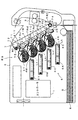
図1は本発明にかかる光走査装置の一実施形態を装備した画像形成装置を示す図である。この画像形成装置は、いわゆるタンデム方式のカラープリンタであり、潜像担持体としてイエロー(Y),マゼンタ(M),シアン(C),ブラック(K)の4色の感光体2Y,2M,2C,2Kを装置本体5内に並設している。そして、各感光体2Y,2M,2C,2K上のトナー像を重ね合わせてフルカラー画像を形成したり、ブラック(K)のトナー像のみを用いてモノクロ画像を形成する装置である。すなわち、この画像形成装置では、ユーザからの画像形成要求に応じてホストコンピュータなどの外部装置から画像形成指令がコントローラ1に与えられると、このコントローラ1からの画像信号、基準信号および各種の制御信号に応じてエンジン部EGが作動して複写紙、転写紙、用紙およびOHP用透明シートなどのシートSに画像形成指令に対応する画像を形成する。
FIG. 1 is a diagram showing an image forming apparatus equipped with an embodiment of an optical scanning device according to the present invention. This image forming apparatus is a so-called tandem type color printer, and yellow (Y), magenta (M), cyan (C), and black (K) photoconductors 2Y, 2M, and 2C as latent image carriers. , 2K are arranged in the apparatus
このエンジン部EGでは、4つの感光体2Y,2M,2C,2Kのそれぞれに対応して帯電ユニット,現像ユニット,露光ユニットおよびクリーニング部が設けられている。このように,各トナー色ごとに,感光体,帯電ユニット,現像ユニット,露光ユニットおよびクリーニング部を備えて該トナー色のトナー像を形成する画像形成手段が設けられている。そして,コントローラ1からの信号に応じて画像形成手段の各部が制御されて画像形成が実行される。なお,これらの画像形成手段(感光体,帯電ユニット,現像ユニット,露光ユニットおよびクリーニング部)の構成はいずれの色成分についても同一であるため,ここではイエローに関する構成について説明し,その他の色成分については相当符号を付して説明を省略する。
In the engine unit EG, a charging unit, a developing unit, an exposure unit, and a cleaning unit are provided corresponding to each of the four photosensitive members 2Y, 2M, 2C, and 2K. As described above, for each toner color, an image forming unit that includes a photoreceptor, a charging unit, a developing unit, an exposure unit, and a cleaning unit and forms a toner image of the toner color is provided. Then, each part of the image forming means is controlled in accordance with a signal from the
感光体2Yは図1の矢印方向(副走査方向)に回転自在に設けられている。より具体的には,感光体2Yの一方端部には,駆動モータ(図示省略)が機械的に接続されており、コントローラ1からの回転駆動指令に基づき駆動制御される。これによって感光体2Yが回転移動する。また、このようにして駆動される感光体2Yの周りにその回転方向に沿って、帯電ユニット3Y、現像ユニット4Yおよびクリーニング部(図示省略)がそれぞれ配置されている。帯電ユニット3Yは例えばスコロトロン帯電器で構成されており、コントローラ1からの帯電バイアス印加によって感光体2Yの外周面を所定の表面電位に均一に帯電させる。そして、この帯電ユニット3Yによって帯電された感光体2Yの外周面に向けて露光ユニット6Yから走査光ビームLyが照射される。これによって画像形成指令に含まれるイエロー画像データに対応する静電潜像が感光体2Y上に形成される。このように露光ユニット6(6Y,6M,6C,6K)が本発明にかかる光走査装置の一実施形態となっている。なお、露光ユニット6および露光ユニットを制御するための露光制御部の構成および動作については後で詳述する。
The photoreceptor 2Y is rotatably provided in the arrow direction (sub-scanning direction) in FIG. More specifically, a drive motor (not shown) is mechanically connected to one end of the
こうして形成された静電潜像は現像ユニット4Yによってトナー現像される。この現像ユニット4Yはイエロートナーを内蔵している。そして、コントローラ1から現像バイアスが現像ローラ41Yに印加されると、現像ローラ41Y上に担持されたトナーが感光体2Yの表面各部にその表面電位に応じて部分的に付着する。その結果、感光体2Y上の静電潜像がイエローのトナー像として顕像化される。なお、現像ローラ41Yに与える現像バイアスとしては、直流電圧、もしくは直流電圧に交流電圧を重畳したもの等を用いることができるが、特に感光体2Yと現像ローラ41Yとを離間配置し、両者の間でトナーを飛翔させることでトナー現像を行う非接触現像方式の画像形成装置では、効率よくトナーを飛翔させるために直流電圧に対して正弦波、三角波、矩形波等の交流電圧を重畳した電圧波形とすることが好ましい。
The electrostatic latent image formed in this way is developed with toner by the developing unit 4Y. The developing unit 4Y contains yellow toner. When a developing bias is applied from the
現像ユニット4Yで現像されたイエロートナー像は、一次転写領域TRy1で転写ユニット7の中間転写ベルト71上に一次転写される。また、イエロー以外の色成分についても、イエローと全く同様に構成されており、感光体2M、2C、2K上にマゼンタトナー像、シアントナー像、ブラックトナー像がそれぞれ形成されるとともに、一次転写領域TRm1、TRc1、TRk1でそれぞれ中間転写ベルト71上に一次転写される。
The yellow toner image developed by the developing unit 4Y is primarily transferred onto the
この転写ユニット7は、2つのローラ72、73に掛け渡された中間転写ベルト71と、ローラ72を回転駆動することで中間転写ベルト71を所定の回転方向R2に回転させるベルト駆動部(図示省略)とを備えている。また、中間転写ベルト71を挟んでローラ73と対向する位置には、該ベルト71表面に対して不図示の電磁クラッチにより当接・離間移動可能に構成された二次転写ローラ74が設けられている。そして、カラー画像をシートSに転写する場合には、一次転写タイミングを制御することで各トナー像を重ね合わせてカラー画像を中間転写ベルト71上に形成するとともに、カセット8から取り出されて中間転写ベルト71と二次転写ローラ74との間の二次転写領域TR2に搬送されてくるシートS上にカラー画像を二次転写する。一方、モノクロ画像をシートSに転写する場合には、ブラックトナー像のみを感光体2Kに形成するとともに、二次転写領域TR2に搬送されてくるシートS上にモノクロ画像を二次転写する。また、こうして画像の2次転写を受けたシートSは定着ユニット9を経由して装置本体の上面部に設けられた排出トレイ部に向けて搬送される。
The
なお、中間転写ベルト71へトナー像を一次転写した後の各感光体2Y,2M,2C,2Kは、不図示の除電手段によりその表面電位がリセットされ、さらに、その表面に残留したトナーがクリーニング部により除去された後、帯電ユニット3Y,3M,3C,3Kにより次の帯電を受ける。
The surface potential of each of the photoreceptors 2Y, 2M, 2C, and 2K after the toner image is primarily transferred to the
また、ローラ72の近傍には、転写ベルトクリーナ75が図示を省略する電磁クラッチによってローラ72に対して近接・離間移動可能となっている。そして、ローラ72側に移動した状態でクリーナ75のブレードがローラ72に掛け渡された中間転写ベルト71の表面に当接し、二次転写後に中間転写ベルト71の外周面に残留付着しているトナーを除去する。
In the vicinity of the
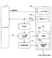
図2は本発明の光走査装置の一実施形態たる露光ユニットの構成を示す主走査断面図、図3は図2の露光ユニット(光走査装置)における光ビームの走査領域を示す図、図4は図1の画像形成装置の露光ユニットおよび露光ユニットを制御するための露光制御部(本発明の「制御手段」に相当)の構成を示す図である。以下、これらの図面を参照しつつ、露光ユニット6、露光制御部(ミラー駆動制御部111、周波数制御部112および計測部113)の構成および動作について詳述する。なお、この実施形態では、各色ごとに露光ユニット6、ミラー駆動制御部111、および計測部113を有しているが、それらの構成はいずれの色成分についても同一であるため、ここではイエローに関する構成について説明し、その他の色成分については相当符号を付して説明を省略する。
2 is a main scanning sectional view showing the configuration of an exposure unit as an embodiment of the optical scanning apparatus of the present invention, FIG. 3 is a diagram showing a scanning region of a light beam in the exposure unit (optical scanning apparatus) of FIG. FIG. 2 is a view showing a configuration of an exposure unit of the image forming apparatus of FIG. 1 and an exposure control unit (corresponding to “control means” of the present invention) for controlling the exposure unit. Hereinafter, the configurations and operations of the
この露光ユニット6Y(6M,6C,6K)は露光筐体61を有している。そして、露光筐体61に単一のレーザー光源62が固着されており、レーザー光源62から光ビームを射出可能となっている。このレーザー光源62には、図4に示すように、コントローラ1から出力される画像信号Svが入力される。この画像信号Svは画像形成指令に含まれるイエロー画像データに対応する信号であり、この画像信号Svに応じてレーザー光源62がON/OFF制御されてレーザー光源62からイエロー画像データに対応して変調された光ビームLyが射出される。
The
また、この露光筐体61の内部には、レーザー光源62からの光ビームを感光体2Yの表面(図示省略)に走査露光するために、コリメータレンズ631、シリンドリカルレンズ632、偏向器65、走査レンズ66が設けられている。すなわち、レーザー光源62からの光ビームは、コリメータレンズ631により適当な大きさのコリメート光にビーム整形された後、副走査方向Yにのみパワーを有するシリンドリカルレンズ632に入射される。そして、シリンドリカルレンズ632を調整することでコリメート光は副走査方向Yにおいて偏向器65の偏向ミラー面651付近で結像される。このように、この実施形態では、コリメータレンズ631およびシリンドリカルレンズ632がレーザー光源62からの光ビームを整形するビーム整形系63として機能している。
Further, in the exposure housing 61, a collimator lens 631, a cylindrical lens 632, a
この偏向器65は半導体製造技術を応用して微小機械を半導体基板上に一体形成するマイクロマシニング技術を用いて形成されるものであり、共振振動する振動ミラーで構成されている。すなわち、偏向器65では、共振振動する偏向ミラー面(振動ミラー面)651により光ビームを主走査方向Xに偏向可能となっている。より具体的には、偏向ミラー面651は主走査方向Xとほぼ直交する駆動軸(ねじりバネ)周りに揺動自在に軸支されるとともに、作動部652から与えられる外力に応じて駆動軸周りに揺動する。この作動部652はミラー駆動制御部111からのミラー駆動信号に基づき偏向ミラー面651に対して静電気的、電磁気的あるいは機械的な外力を作用させて偏向ミラー面651を予め設定された駆動周波数で振動させる。なお、作動部652による駆動方式は静電吸着、電磁気力あるいは機械力などのいずれの方式を採用してもよく、それらの駆動方式は周知であるため、ここでは説明を省略する。
The
このようにして駆動される偏向器65には、例えば特開平9−197334号公報に記載されたような共振周波数調整部653が設けられており、偏向器65の共振周波数を変化させることが可能となっている。すなわち、この共振周波数調整部653では偏向器65のねじりバネ(図示省略)に電気抵抗素子が形成されるとともに、該電気抵抗素子が露光制御部の周波数制御部112と電気的に接続されている。そして、周波数制御部112による電気抵抗素子への通電制御によりねじりバネの温度が変化する。これによって、ねじりバネのバネ定数が変化し、偏向器65の共振周波数を変更させることができる。このように偏向器65の共振周波数を駆動制御量とし、共振周波数を変化させることで偏向ミラー面651の振幅角を制御可能となっている。そこで、この実施形態では、後述するように共振周波数が予め設定された駆動周波数と不一致である場合には、共振周波数調整部653により偏向器65の共振周波数を変動させて駆動周波数とほぼ一致させている。なお、偏向器65の共振周波数を変化させる具体的な構成はこれに限定されるものではなく、従来より周知の構成を採用することができる。
The
また、ミラー駆動制御部111はミラー駆動信号の周波数や電圧などの駆動条件、つまり駆動制御量を変更設定することができるように構成されている。したがって、必要に応じてミラー駆動信号の周波数を変更設定することが可能となっている。また、ミラー駆動信号の電圧を変更させることで振幅値を調整することも可能となっている。
Further, the mirror
そして、偏向器65の偏向ミラー面651で偏向された光ビームは走査レンズ66に向けて偏向される。この実施形態では、走査レンズ66は、感光体2の表面上の有効走査領域ESRの全域においてF値が略同一となるように構成されている。したがって、走査レンズ66に向けて偏向された光ビームは、走査レンズ66を介して感光体2Yの表面の有効走査領域ESRに略同一のスポット径で結像される。これにより、光ビームが主走査方向Xと平行に走査して主走査方向Xに伸びるライン状の潜像が感光体2の表面上に形成される。なお、この実施形態では、偏向器65により走査可能な走査範囲(本発明の「第2走査領域」)SR2は、図3に示すように、有効走査領域ESR上で光ビームを走査させるための走査範囲(本発明の「第1走査範囲」)SR1よりも広く設定されている。また、第1走査範囲SR1が第2走査範囲SR2の略中央部に位置しており、光軸に対してほぼ対称となっている。さらに、同図中の符号θirは有効走査領域ESRの端部に対応する偏向ミラー面651の振幅角を示し、符号θsは次に説明する光検出センサに対応する偏向ミラー面651の振幅角を示している。
Then, the light beam deflected by the deflecting mirror surface 651 of the
また、この実施形態では、図2に示すように、走査光ビームの走査経路の一方端を折り返しミラー69aにより光検出センサ60に導いている。この折り返しミラー69aは第2走査範囲SR2の一方端部に配置され、第2走査範囲SR2内で、かつ第1走査範囲SR1を外れた位置を移動する走査光ビームを光検出センサ60に導光する。そして、光検出センサ60により該走査光ビームが受光されてセンサ位置(Hsync相当角θs)を通過するタイミングで信号が光検出センサ60から出力される。
In this embodiment, as shown in FIG. 2, one end of the scanning path of the scanning light beam is guided to the
この光検出センサ60による走査光ビームの検出信号Hsyncは露光制御部の計測部113に伝達され、該計測部113において偏向器65の振幅角、有効走査領域ESRを光ビームが走査する走査時間や駆動周期などに関連する駆動情報が算出される。そして、この計測部113において算出された実測情報がミラー駆動制御部111に伝達され、ミラー駆動制御部111は後述するように駆動制御量の変更禁止、該変更禁止の解除、振幅制御やミラー駆動の停止処理などを行う。
The detection signal Hsync of the scanning light beam by the
また、光検出センサ60からの水平同期信号Hsyncはコントローラ1にも直接入力されており、光ビームが有効走査領域ESRを主走査方向Xに走査する際の同期信号として機能させている。すなわち、このセンサ60は水平同期信号Hsyncを得るための水平同期用読取センサとして機能している。
Further, the horizontal synchronization signal Hsync from the
ところで、上記のように構成された装置では、偏向器65が振動停止している状態で画像形成指令が与えられると、画像形成開始前に起動処理を実行して光ビームがコントローラ1と同期しながら偏向器65によって良好に走査されるように調整している。すなわち、偏向器65を作動させるための駆動制御量を予めメモリ(図示省略)に記憶されている初期値に設定する。より具体的には、ミラー駆動信号および共振周波数調整部653に与える信号の電気特性値(周波数、電圧や電流)をメモリから読み出し、設定している。そして、初期設定の完了後に、上記した初期値でミラー駆動が開始される。このとき、偏向器65の振幅は例えば図5(a)に示すようにゼロから徐々に増大していく。そして、振幅角がHsync相当角θsに達する、つまり走査光ビームを光検出センサ60を通過するタイミングで信号Hsyncが光検出センサ60から出力される。この後、光検出センサ60からの検出信号Hsyncに基づく振幅制御が実行される。なお、この実施形態では、短時間に続けて光検出センサ60から出力される2つの信号Hsyncの時間差Tnpに基づき振幅制御を行っている。すなわち、振動ミラーにより構成された偏向器65を用いた装置では、有効走査領域ESRから遠ざかる方向に走査移動している光ビームが光検出センサ60を通過すると、第1検出信号Hsyncが出力される。その後、走査光ビームは最大振幅角θmaxで反転動作した偏向ミラー面651により走査方向が反転される。そして、走査光ビームが有効走査領域ESRに向かって移動し、センサ位置(Hsync相当角θs)を通過するタイミングで第2検出信号Hsyncが光検出センサ60から出力される。このように、この実施形態では、有効走査領域ESRから光検出センサ60を経由して再び有効走査領域ESRに戻る往復光ビームを光検出センサ60が検出して該検出に応じて信号Hsyncを出力している。また、これらの検出信号Hsyncは偏向器65の振動周期ごとに出力され、各振動周期(振幅の1周期に相当)での第1および第2検出信号Hsyncの間隔Tnpは最大振幅角θmaxに関連している。そこで、この実施形態では、計測部113において第1および第2検出信号の間隔Tnpを振幅角に関連する振幅関連情報として求めてミラー駆動制御部111に与えている。また、ミラー駆動制御部111は計測部113からの振幅関連情報とコントローラ1から与えられる信号Sdで示される振幅目標値とに基づき作動部652に与えるミラー駆動信号の電圧や電流を調整している。なお、振幅制御の具体的な手法については、これに限定されるものではなく、従来より周知の振幅制御を用いることができる。
By the way, in the apparatus configured as described above, when an image formation command is given in a state where the
このように起動処理では、停止状態の振動ミラーに対して駆動信号を与えて駆動を開始させ、検出信号Hsyncが得られた時点で振幅制御に移行しているが、偏向器65の振幅角が光検出センサ60の配設位置に対応する角度θs以上となっているにもかかわらず、振幅制御のために必要な検出信号Hsyncが光検出センサ60から出力されないことがある。その原因として、例えばレーザー光源62や光検出センサ60の故障あるいはノイズによる影響などが挙げられる。このように検出信号Hsyncが得られない場合には、例えば同図(b)に示すように、センシング不良が発生し、光検出センサ60からの検出信号Hsyncに基づく振幅制御に移行することができず、偏向器65をさらに加振させて破壊させてしまうことがある。
As described above, in the start process, the drive signal is given to the oscillating mirror in the stopped state to start the drive, and when the detection signal Hsync is obtained, the control shifts to the amplitude control. The detection signal Hsync necessary for amplitude control may not be output from the
また、振幅制御が正常に行われている間においては、第1および第2検出信号Hsyncの間隔Tnpはほぼ一定であり、例えば図6(a)に示すように、これら2つの連続する検出信号Hsyncに基づき駆動制御量が調整されて最大振幅角θmaxは振幅目標値となっている。しかしながら、振幅制御に移行した後に、センサ等の故障あるいはノイズによる影響により検出信号Hsyncが出力されなかったり、逆にノイズの影響により光ビームが光検出センサ60を通過するタイミングとは異なるタイミングでセンサ60から信号が出力されてしまうことがある。この場合には、例えば同図(b)に示すように、ミラー駆動制御部111は不適正なミラー駆動信号を偏向器65の作動部652に与えてしまい、偏向器65の振幅角が大きく変動してしまうことがある。特に、センサ故障やノイズなどの影響が偏向器65を加振する方向に作用すると、偏向器65の破壊が発生する。
While the amplitude control is normally performed, the interval Tnp between the first and second detection signals Hsync is substantially constant. For example, as shown in FIG. The drive control amount is adjusted based on Hsync, and the maximum amplitude angle θmax is the amplitude target value. However, after shifting to amplitude control, the detection signal Hsync is not output due to a failure of the sensor or the like or the influence of noise, or conversely, the sensor at a timing different from the timing at which the light beam passes through the
そこで、この実施形態では、起動処理および振幅制御処理の各々において、振幅制御に必要な検出信号Hsyncが得られないときには、駆動制御量の変更を禁止して偏向器65の作動部652に対して不適切な駆動制御量が与えられるのを防止して偏向器65の破壊を確実に防止している。以下、起動処理における露光ユニット(光走査装置)6の制御と、振幅制御処理における露光ユニット(光走査装置)6の制御とに分けて詳述する。
Therefore, in this embodiment, when the detection signal Hsync necessary for amplitude control is not obtained in each of the start-up process and the amplitude control process, the change of the drive control amount is prohibited and the
<起動処理における露光ユニットの制御>
図7は図1の画像形成装置で実行される起動処理を示すフローチャートである。また、図8ないし図10は起動処理の動作を示す図である。この起動が開始されると、ステップS1で偏向器65を作動させるための駆動制御量を予めメモリ(図示省略)に記憶されている初期値に設定する。より具体的には、ミラー駆動信号および共振周波数調整部653に与える信号の電気特性値(周波数、電圧や電流)をメモリから読み出し、設定している。また、検出信号Hsyncの検出までの時間を示すカウント値Cをリセットした後、カウント値Cのカウントを開始する(ステップS2)。また、検出信号Hsyncの出力数を示すカウント値Nをゼロにリセットする(ステップS3)。
<Control of exposure unit in start-up process>
FIG. 7 is a flowchart showing a startup process executed by the image forming apparatus of FIG. 8 to 10 are diagrams showing the operation of the startup process. When this activation is started, a drive control amount for operating the
こうして、初期設定が完了すると、上記した初期値でミラー駆動が開始される(ステップS4)。このとき、偏向器65の振幅は図5、図8ないし図10に示すようにゼロから徐々に増大していく。そして、露光ユニット6が正常に動作している場合には、図5(a)および図8に示すように、振幅角がHsync相当角θsに達する、つまり走査光ビームを光検出センサ60を通過するタイミングで信号Hsyncが光検出センサ60から出力される。これにより、レーザー光源62からの光ビームの射出が確認されるとともに、光検出センサ60からの検出信号Hsyncに基づく振幅制御が可能となる。
Thus, when the initial setting is completed, mirror driving is started with the above-described initial value (step S4). At this time, the amplitude of the
そこで、この実施形態では、カウント値Cが時間Tmsに相当するカウント値C1に達するまでに検出信号Hsyncが4回以上出力されるのを確認する(ステップS5〜S8)と、起動処理を終了して振幅制御に移行する。ここで、カウント値C1を設定している理由は次のとおりである。偏向器65の駆動開始段階では、偏向器65の振幅は小さく、初期値を如何なる値に設定したとしても、共振振動する偏向器65の振幅角がHsync相当角θsに達するには、ある程度の時間Thsが要する。したがって、所定時間Tmsを時間Ths以上に設定するのが望ましく、例えば、初期値で偏向器65を駆動した際に、最初に光検出センサ60から検出信号Hsyncが出力されるまでの時間Thsに、さらに続けて例えば3つの検出信号Hsyncが出力される時間を加えた時間Ts3を所定時間Tms(=Ths+Ts3)とすることができる。また、この実施形態では、検出信号Hsyncの初期検出精度を高めるために、本発明の「振幅制御に必要な検出信号」として、駆動開始から所定時間Tms(カウント値C1)の間に4本の検出信号Hsyncが出力されることを条件に振幅制御に移行しているが、検出信号Hsyncの個数、つまりカウント値Nは「4」に限定されるものではなく、「1」以上の値を設定することができる。
Therefore, in this embodiment, when it is confirmed that the detection signal Hsync is output four or more times until the count value C reaches the count value C1 corresponding to the time Tms (steps S5 to S8), the activation process is terminated. Shift to amplitude control. Here, the reason for setting the count value C1 is as follows. At the driving start stage of the
一方、カウント値Cが時間Tmsに相当するカウント値C1に達するまでに検出信号Hsyncが4回以上出力されるのを確認することができなかった(ステップS5で「YES」と判定された)場合には、駆動制御量の変更を禁止して現時点での駆動制御量を保持する(ステップS9)。このように本実施形態では、起動処理においては、上記時間Tmsが本発明の請求項2記載の「第1の時間」に相当している。 On the other hand, when it cannot be confirmed that the detection signal Hsync is output four times or more before the count value C reaches the count value C1 corresponding to the time Tms (determined as “YES” in step S5). In step S9, the change of the drive control amount is prohibited and the current drive control amount is held (step S9). Thus, in this embodiment, the activation process, the time Tms corresponds to the "first time" according to a second aspect of the present invention.
次のステップS10では、カウント値Cをリセットし、さらにステップS11で検出信号Hsyncの出力数を示すカウント値Lをゼロにリセットする。そして、カウント値Cがカウント値C2に達するまでに検出信号Hsyncが4回以上出力されるのを確認する(ステップS12〜S15)と、駆動制御量の変更禁止を解除するとともに、起動処理を終了して振幅制御に移行する(図9参照)。ここで、カウント値C2を設定している理由は次のとおりである。レーザー光源62や光検出センサ60の故障により光検出センサ60から検出信号Hsyncが適正に出力されない場合には、時間Tmsが経過した後においても光検出センサ60から検出信号Hsyncが適正に出力されない可能性が高い。これに対し、ノイズの影響により時間Tmsの間に検出信号Hsyncが出力されなかったとしても、その後に検出信号Hsyncが出力される可能性がある。
In the next step S10, the count value C is reset, and in step S11, the count value L indicating the number of outputs of the detection signal Hsync is reset to zero. Then, when it is confirmed that the detection signal Hsync is output four or more times until the count value C reaches the count value C2 (steps S12 to S15), the prohibition of changing the drive control amount is canceled and the start-up process is terminated. Then, the control shifts to amplitude control (see FIG. 9). Here, the reason for setting the count value C2 is as follows. If the detection signal Hsync is not properly output from the
そこで、この実施形態では、検出信号Hsyncの検出を2段階に分けており、カウント値C2を設定するにあたっては、次の点を考慮する必要がある。つまり、時間経過とともに最大振幅角θmaxが徐々に増大して破壊限界角を超えると、偏向器65が破壊されてしまうため、これを防止するためには、初期値で偏向器65を駆動した際に最大振幅角θmaxが破壊限界角に達するまでに要する時間Tdsまでに検出信号Hsyncの有無を確認する必要がある。そこで、この実施形態では、カウント値C2を時間(Tds−Tms)に相当する値以下に設定することができる。
Therefore, in this embodiment, detection of the detection signal Hsync is divided into two stages, and the following points need to be considered when setting the count value C2. That is, when the maximum amplitude angle θmax gradually increases with the passage of time and exceeds the destruction limit angle, the
また、この実施形態では、検出信号Hsyncの初期検出精度を高めるために、所定時間Tms(カウント値C1)を経過した後に所定時間(<Tds−Tms)の間に4本の検出信号Hsyncが出力されることを条件に振幅制御に移行しているが、検出信号Hsyncの個数、つまりカウント値Lは「4」に限定されるものではなく、「1」以上の値を設定することができる。 In this embodiment, in order to increase the initial detection accuracy of the detection signal Hsync, four detection signals Hsync are output during a predetermined time (<Tds−Tms) after a predetermined time Tms (count value C1) has elapsed. However, the number of detection signals Hsync, that is, the count value L is not limited to “4”, and a value of “1” or more can be set.
一方、図10に示すように、カウント値Cがカウント値C2に達するまでに検出信号Hsyncが4回以上出力されるのを確認することができなかった(ステップS12で「YES」と判定された)場合には、ミラー駆動が停止される(ステップS16)。このように本実施形態の起動処理では、カウント値C2に対応する時間が本発明の「第2の時間」に相当している。 On the other hand, as shown in FIG. 10, it was not possible to confirm that the detection signal Hsync was output four or more times until the count value C reached the count value C2 (“YES” was determined in step S12). ), The mirror drive is stopped (step S16). Thus the startup process of the present embodiment, the time corresponding to the count value C2 corresponds to the "second time" of the present invention.
以上のように、この実施形態によれば、振幅制御に必要な検出信号Hsyncが得られないときには、駆動制御量の変更が禁止され、現時点での駆動制御量を保持したまま偏向器65が駆動される。したがって、偏向器65に対して不適切な駆動制御量が与えられるのを防止して偏向器65の破壊を防止することができる。また、検出信号Hsyncの検出を2段階に分けている。そして、前半の信号検出(ステップS5〜S8)においてノイズなどの影響によって検出信号Hsyncが検出されなかった場合であっても、後半の信号検出(ステップS12〜S15)において検出信号Hsyncが検出されると、振幅制御に移行している。したがって、ノイズ発生・停止に対して適切に対応することができる。さらに、偏向器(振動ミラー)65の駆動開始から所定時間、つまり(カウント値C1+カウント値C2)に相当する時間が経過しても光ビームが検出されなかったときには、偏向器65の駆動を停止しているので、偏向器65の破壊を確実に防止することができる。すなわち、この実施形態では、レーザー光源62や光検出センサ60の故障などが発生したとしても偏向器65の破壊前に偏向器65を確実に停止させることができる。
As described above, according to this embodiment, when the detection signal Hsync necessary for amplitude control cannot be obtained, the change of the drive control amount is prohibited, and the
<振幅制御処理における露光ユニットの制御>
図11は図1の画像形成装置で実行される振幅制御処理を示すフローチャートである。また、図12は振幅制御処理の動作を示す図である。この振幅制御処理では、ステップS21で振幅目標値が設定される。そして、検出信号Hsyncの検出までの時間を示すカウント値Dをリセットした後、カウント値Dのカウントを開始する(ステップS22)。
<Control of exposure unit in amplitude control processing>
FIG. 11 is a flowchart showing an amplitude control process executed by the image forming apparatus of FIG. FIG. 12 shows the operation of the amplitude control process. In this amplitude control process, an amplitude target value is set in step S21. Then, after resetting the count value D indicating the time until the detection signal Hsync is detected, counting of the count value D is started (step S22).
次に、現時点で設定されている駆動制御量を偏向器65の作動部652に与えてミラー駆動を行う(ステップS23)。そして、振幅制御に必要な第1および第2検出信号Hsyncが出力されている間は、偏向器65の振幅は図6や図12に示すように振幅制御により駆動制御量の設定が適切である間は偏向器65の最大振幅角θmaxは振幅目標値とほぼ一致している。すなわち、カウント値Dが所定のカウント値D1に達するまでに第1および第2検出信号Hsyncが出力されるのを確認する(ステップS24〜S26)と、これらの検出信号Hsyncの時間差Tnpに基づき振幅制御を行う(図6(a)参照)。また、振幅制御により駆動制御量が調整されると、ステップS23で設定されている駆動制御量を調整後の駆動制御量と書き換えて更新する(ステップS27)。そして、ステップS22に戻って上記一連の処理を繰り返す。
Next, the drive control amount set at the present time is given to the operating
一方、カウント値Dがカウント値D1に達するまでに振幅制御に必要な第1および第2検出信号Hsyncが出力されるのを確認することができなかった(ステップS24で「YES」と判定された)場合には、駆動制御量の変更を禁止して現時点での駆動制御量を保持する(ステップS28)。このように本実施形態では、振幅制御処理においては、上記カウント値D1に対応する時間が本発明の請求項3記載の「第1の時間」に相当している。
On the other hand, it was not possible to confirm that the first and second detection signals Hsync necessary for amplitude control were output until the count value D reached the count value D1 ("YES" was determined in step S24). ), The change of the drive control amount is prohibited and the current drive control amount is held (step S28). Thus, in this embodiment, the amplitude control process, the time corresponding to the count value D1 corresponds to the "first time" according to
次のステップS29では、カウント値Dをリセットする。そして、カウント値Dがカウント値D2に達するまでに振幅制御に必要な第1および第2検出信号Hsyncが出力されるのを確認する(ステップS30〜S32)と、ステップS32駆動制御量の変更禁止を解除するとともに、ステップS26に進んで振幅制御を行う。 In the next step S29, the count value D is reset. Then, when it is confirmed that the first and second detection signals Hsync necessary for amplitude control are output until the count value D reaches the count value D2 (steps S30 to S32), the change of the drive control amount in step S32 is prohibited. Is canceled, and the process proceeds to step S26 to perform amplitude control.
一方、図12に示すように、カウント値Dがカウント値D2に達するまでに振幅制御に必要な第1および第2検出信号Hsyncが出力されるのを確認することができなかった(ステップS30で「YES」と判定された)場合には、図12に示すように、ミラー駆動が停止される(ステップS33)。このように本実施形態の振幅制御処理では、カウント値D2に対応する時間が本発明の「第2の時間」に相当している。 On the other hand, as shown in FIG. 12, it was not possible to confirm that the first and second detection signals Hsync necessary for amplitude control were output until the count value D reached the count value D2 (in step S30). If “YES” is determined), the mirror drive is stopped as shown in FIG. 12 (step S33). Such an amplitude control process of the present embodiment, the time corresponding to the count value D2 corresponds to the "second time" of the present invention.
以上のように、起動処理と同様に、振幅制御に必要な第1および第2検出信号Hsyncが得られないときには、駆動制御量の変更が禁止され、現時点での駆動制御量を保持したまま偏向器65が駆動される。したがって、偏向器65に対して不適切な駆動制御量が与えられるのを防止して偏向器65の破壊を防止することができる。また、偏向器(振動ミラー)65の駆動開始から所定時間、つまり(カウント値D1+カウント値D2)に相当する時間が経過しても光ビームが検出されなかったときには、偏向器65の駆動を停止しているので、偏向器65の破壊を確実に防止することができる。すなわち、この実施形態では、レーザー光源62や光検出センサ60の故障などが発生したとしても偏向器65の破壊前に偏向器65を確実に停止させることができる。
As described above, when the first and second detection signals Hsync necessary for the amplitude control cannot be obtained, the change of the drive control amount is prohibited and the current drive control amount is maintained while being deflected, as in the start-up process. The
なお、本発明は上記した実施形態に限定されるものではなく、その趣旨を逸脱しない限りにおいて上述したもの以外に種々の変更を行うことが可能である。例えば、上記実施形態では、振幅制御に必要な検出信号Hsyncの検出を2段階に分けているが、次のように構成してもよい。すなわち、振幅制御中に振幅制御に必要な検出信号Hsyncが検出されないときには直ちに駆動制御量の変更を禁止して現時点での駆動制御量に基づいて偏向器65を駆動しながら検出信号Hsyncの出力を待ってもよい。そして、検出信号Hsyncが検出されると、変更禁止を解除して該検出信号Hsyncに応じて駆動制御量を変更するように構成してもよい。このような実施形態においても、上記実施形態と同様に、振幅制御に必要な検出信号Hsyncが検出されないときには現時点での駆動制御量が保持された状態で偏向器65が駆動されるため、偏向器65の破壊を防止することができる。また、検出信号Hsyncを検出すると、振幅制御を行っているので、常に偏向器65を適正に振動させることができる。もちろん、このような実施形態においても、カウント値Dが所定のカウント値に達するまでに検出信号Hsyncが出力されないときにはミラー駆動を停止させるのが望ましい。
The present invention is not limited to the above-described embodiment, and various modifications other than those described above can be made without departing from the spirit of the present invention. For example, in the above-described embodiment, detection of the detection signal Hsync necessary for amplitude control is divided into two stages, but it may be configured as follows. That is, when the detection signal Hsync necessary for amplitude control is not detected during amplitude control, the change of the drive control amount is immediately prohibited, and the detection signal Hsync is output while driving the
また、上記実施形態では、第2走査範囲SR2の一方端部で光ビームを検出して振幅制御する光装置装置に本発明を適用しているが、他方端部で光ビームを検出して振幅制御する装置に対しても本発明を適用することができる。さらに、第2走査範囲SR2のうち、有効走査領域ESRを間に挟み相対する両側端部で光ビームを検出して振幅制御する装置に対しても同様に本発明を適用することができる。 In the above embodiment, the present invention is applied to the optical device that controls the amplitude by detecting the light beam at one end of the second scanning range SR2. However, the amplitude is detected by detecting the light beam at the other end. The present invention can be applied to a device to be controlled. Further, the present invention can be similarly applied to an apparatus that detects an optical beam at both end portions facing each other with the effective scanning region ESR interposed therebetween in the second scanning range SR2.
また、上記実施形態では、タンデム方式のカラー画像形成装置の露光ユニットに本発明にかかる光走査装置を適用しているが、本発明の適用対象はこれに限定されるものではなく、いわゆる4サイクル方式のカラー画像形成装置あるいは単色画像を形成するモノクロ画像形成装置の露光ユニットに本発明を適用することができる。また、光走査装置の適用対象は画像形成装置に装備される露光ユニットに限定されるものではなく、光ビームを被走査面上に走査させる光走査装置全般に適用することができる。 In the above embodiment, the optical scanning apparatus according to the present invention is applied to the exposure unit of the tandem color image forming apparatus. However, the application target of the present invention is not limited to this, and so-called four cycles. The present invention can be applied to an exposure unit of a type color image forming apparatus or a monochrome image forming apparatus for forming a monochromatic image. The application target of the optical scanning device is not limited to the exposure unit provided in the image forming apparatus, and can be applied to all optical scanning devices that scan a scanning surface with a light beam.
さらに、上記実施形態では、振動ミラーとしてマイクロマシニング技術を用いて形成された偏向器65を採用しているが、共振振動する振動ミラーを用いて光ビームを偏向して光ビームを走査させる光走査装置全般に本発明を適用することができる。
Furthermore, in the above-described embodiment, the
60…光検出センサ(検出手段)、 65…偏向器(振動ミラー)、 111…ミラー駆動制御部(制御手段)、 651…偏向ミラー面、 Hsync…水平同期信号(検出信号)、 Ly,Lm,Lc,Lk…(走査)光ビーム、 X…主走査方向 60 ... light detection sensor (detection means), 65 ... deflector (vibrating mirror), 111 ... mirror drive controller (control means), 651 ... deflection mirror surface, Hsync ... horizontal synchronization signal (detection signal), Ly, Lm, Lc, Lk (scanning) light beam, X ... main scanning direction
Claims (7)
振動する振動ミラーと、
前記振動ミラーによって、前記光源から射出された前記光ビームを偏向して、前記振動ミラーの振動する際の駆動軸方向に対して直交又はほぼ直交する第一方向で、有効走査領域を含むとともに当該有効走査領域を超える範囲を走査する走査手段と、
前記有効走査領域に対応する範囲を外れた前記第一方向の位置に設けられ、前記第一方向で走査する前記光ビームを検出して検出信号を出力する検出手段と、
前記検出信号に基づき、前記振動ミラーに与える駆動制御量を調整し、前記振動ミラーの振幅を制御する制御手段とを備え、
前記制御手段は、メモリに記憶する初期値に前記駆動制御量を設定して前記振動ミラーの駆動を開始する起動処理を行う際に、前記検出信号が得られない場合、前記調整による前記駆動制御量の変更を禁止し、当該禁止した時点での前記駆動制御量を保持し、当該保持された駆動制御量で前記振動ミラーの振幅を制御することを特徴とする光走査装置。 A light source that emits a light beam;
A vibrating mirror to vibrate;
The oscillating mirror deflects the light beam emitted from the light source and includes an effective scanning area in a first direction orthogonal or substantially orthogonal to the drive axis direction when the oscillating mirror vibrates. Scanning means for scanning a range exceeding the effective scanning area ;
Detection means provided at a position in the first direction outside the range corresponding to the effective scanning region, detecting the light beam scanning in the first direction and outputting a detection signal;
Adjusting a drive control amount given to the oscillating mirror based on the detection signal, and a control means for controlling the amplitude of the oscillating mirror;
The control means sets the drive control amount to an initial value stored in a memory and performs the startup process to start driving the vibrating mirror, and when the detection signal is not obtained, the drive control by the adjustment prohibits changing amount, it holds the drive control amount at the time of the said prohibition, an optical scanning device and controls the amplitude of the vibration mirror drive control amount to which the held.
振動する振動ミラーと、
前記振動ミラーによって、前記光源から射出された前記光ビームを偏向して、前記振動ミラーの振動する際の駆動軸方向に対して直交又はほぼ直交する第一方向で、有効走査領域を含むとともに当該有効走査領域を超える範囲を走査する走査手段と、
前記有効走査領域に対応する範囲を外れた前記第一方向の位置に設けられ、前記第一方向で走査する前記光ビームを検出して検出信号を出力する検出手段と、
前記検出信号に基づき、前記振動ミラーに与える駆動制御量を調整し、前記振動ミラーの振幅を制御する制御手段とを備え、
前記制御手段は、駆動された状態にある前記振動ミラーの振幅を制御する振幅制御処理を行う際に、前記検出信号が得られない場合、前記調整による前記駆動制御量の変更を禁止し、当該禁止した時点での前記駆動制御量を保持し、当該保持された駆動制御量で前記振動ミラーの振幅を制御することを特徴とする光走査装置。 A light source that emits a light beam;
A vibrating mirror to vibrate;
The oscillating mirror deflects the light beam emitted from the light source and includes an effective scanning area in a first direction orthogonal or substantially orthogonal to the drive axis direction when the oscillating mirror vibrates. Scanning means for scanning a range exceeding the effective scanning area ;
Detection means provided at a position in the first direction outside the range corresponding to the effective scanning area, and detecting the light beam scanning in the first direction and outputting a detection signal;
Adjusting a drive control amount given to the oscillating mirror based on the detection signal, and a control means for controlling the amplitude of the oscillating mirror;
When the detection signal is not obtained when performing the amplitude control process for controlling the amplitude of the oscillating mirror in the driven state , the control means prohibits the change of the drive control amount by the adjustment, and An optical scanning device characterized in that the drive control amount at the time of prohibition is held, and the amplitude of the vibrating mirror is controlled by the held drive control amount.
前記有効走査領域に対応する範囲を外れた前記第一方向の位置に設けられる検出手段が、前記第一方向で走査する前記光ビームを検出して出力する検出信号に基づき、前記振動ミラーに与える駆動制御量を調整し、前記振動ミラーの振幅を制御する光走査装置の制御方法であって、
メモリに記憶する初期値に前記駆動制御量を設定して前記振動ミラーの駆動を開始する起動処理で前記検出信号が出力されたか否かを判定する工程と、
前記判定工程において前記検出信号が得られない場合、前記駆動制御量の変更を禁止し、当該禁止した時点での前記駆動制御量を保持し、当該保持された駆動制御量で前記振動ミラーの振幅を制御する工程と
を備えたことを特徴とする光走査装置の制御方法。 A light beam emitted from a light source is scanned by a vibrating mirror in a first direction orthogonal or substantially orthogonal to the drive axis direction when the vibrating mirror vibrates , including an effective scanning area and a range exceeding the effective scanning area. In the optical scanning device to be
Detection means provided at a position in the first direction outside the range corresponding to the effective scanning region gives the vibrating mirror based on a detection signal output by detecting and outputting the light beam scanned in the first direction. A method of controlling an optical scanning device that adjusts a drive control amount and controls the amplitude of the oscillating mirror,
Determining whether or not the detection signal is output in an activation process of setting the drive control amount to an initial value stored in a memory and starting driving the vibrating mirror ;
If the determination step the no detection signal is obtained at, it prohibits changing of the drive control amount, holding the drive control amount at the time of the said prohibition, of the vibrating mirror driven control amount to which the held amplitude And a method for controlling the optical scanning device.
前記有効走査領域に対応する範囲を外れた前記第一方向の位置に設けられる検出手段が、前記第一方向で走査する前記光ビームを検出して出力する検出信号に基づき、前記振動ミラーに与える駆動制御量を調整し、前記振動ミラーの振幅を制御する光走査装置の制御方法であって、
駆動された状態にある前記振動ミラーの振幅を制御する振幅制御処理で前記検出信号が出力されたか否かを判定する工程と、
前記判定工程において前記検出信号が得られない場合、前記駆動制御量の変更を禁止し、当該禁止した時点での前記駆動制御量を保持し、当該保持された駆動制御量で前記振動ミラーの振幅を制御する工程と
を備えたことを特徴とする光走査装置の制御方法。 A light beam emitted from a light source is scanned by a vibrating mirror in a first direction orthogonal or substantially orthogonal to the drive axis direction when the vibrating mirror vibrates , including an effective scanning area and a range exceeding the effective scanning area. In the optical scanning device to be
Detection means provided at a position in the first direction outside the range corresponding to the effective scanning region gives the vibrating mirror based on a detection signal output by detecting and outputting the light beam scanned in the first direction. A method of controlling an optical scanning device that adjusts a drive control amount and controls the amplitude of the oscillating mirror,
Determining whether the detection signal is output in an amplitude control process for controlling the amplitude of the vibrating mirror in a driven state ;
If the determination step the no detection signal is obtained at, it prohibits changing of the drive control amount, holding the drive control amount at the time of the said prohibition, of the vibrating mirror driven control amount to which the held amplitude And a method for controlling the optical scanning device.
Priority Applications (1)
| Application Number | Priority Date | Filing Date | Title |
|---|---|---|---|
| JP2005241391A JP4720368B2 (en) | 2005-08-23 | 2005-08-23 | Optical scanning apparatus and method for controlling the apparatus |
Applications Claiming Priority (1)
| Application Number | Priority Date | Filing Date | Title |
|---|---|---|---|
| JP2005241391A JP4720368B2 (en) | 2005-08-23 | 2005-08-23 | Optical scanning apparatus and method for controlling the apparatus |
Publications (3)
| Publication Number | Publication Date |
|---|---|
| JP2007057695A JP2007057695A (en) | 2007-03-08 |
| JP2007057695A5 JP2007057695A5 (en) | 2008-10-09 |
| JP4720368B2 true JP4720368B2 (en) | 2011-07-13 |
Family
ID=37921280
Family Applications (1)
| Application Number | Title | Priority Date | Filing Date |
|---|---|---|---|
| JP2005241391A Expired - Fee Related JP4720368B2 (en) | 2005-08-23 | 2005-08-23 | Optical scanning apparatus and method for controlling the apparatus |
Country Status (1)
| Country | Link |
|---|---|
| JP (1) | JP4720368B2 (en) |
Families Citing this family (3)
| Publication number | Priority date | Publication date | Assignee | Title |
|---|---|---|---|---|
| JP4925999B2 (en) * | 2007-10-31 | 2012-05-09 | パナソニック電工Sunx株式会社 | Galvano drive device and laser processing device |
| JP5491004B2 (en) * | 2008-06-20 | 2014-05-14 | キヤノン電子株式会社 | OPTICAL SCANNING DEVICE, IMAGE FORMING DEVICE USING THE OPTICAL SCANNING DEVICE, IMAGE READING DEVICE, AND DISPLAY DEVICE |
| JP5048595B2 (en) * | 2008-06-20 | 2012-10-17 | キヤノン電子株式会社 | Optical scanning device and image forming apparatus using the optical scanning device |
Citations (7)
| Publication number | Priority date | Publication date | Assignee | Title |
|---|---|---|---|---|
| JPH08174902A (en) * | 1994-12-26 | 1996-07-09 | Canon Inc | Image-recording apparatus |
| JPH09230278A (en) * | 1996-02-20 | 1997-09-05 | Brother Ind Ltd | Optical scanner |
| JP2002082304A (en) * | 2000-09-08 | 2002-03-22 | Sunx Ltd | Galvanic driver |
| JP2005208460A (en) * | 2004-01-26 | 2005-08-04 | Seiko Epson Corp | Optical scanner and image forming apparatus |
| JP2005208459A (en) * | 2004-01-26 | 2005-08-04 | Seiko Epson Corp | Optical scanner and image forming apparatus |
| JP2007041339A (en) * | 2005-08-04 | 2007-02-15 | Seiko Epson Corp | Optical scanner and method of controlling the same |
| JP2007041257A (en) * | 2005-08-03 | 2007-02-15 | Seiko Epson Corp | Optical scanner and method of controlling the same |
-
2005
- 2005-08-23 JP JP2005241391A patent/JP4720368B2/en not_active Expired - Fee Related
Patent Citations (7)
| Publication number | Priority date | Publication date | Assignee | Title |
|---|---|---|---|---|
| JPH08174902A (en) * | 1994-12-26 | 1996-07-09 | Canon Inc | Image-recording apparatus |
| JPH09230278A (en) * | 1996-02-20 | 1997-09-05 | Brother Ind Ltd | Optical scanner |
| JP2002082304A (en) * | 2000-09-08 | 2002-03-22 | Sunx Ltd | Galvanic driver |
| JP2005208460A (en) * | 2004-01-26 | 2005-08-04 | Seiko Epson Corp | Optical scanner and image forming apparatus |
| JP2005208459A (en) * | 2004-01-26 | 2005-08-04 | Seiko Epson Corp | Optical scanner and image forming apparatus |
| JP2007041257A (en) * | 2005-08-03 | 2007-02-15 | Seiko Epson Corp | Optical scanner and method of controlling the same |
| JP2007041339A (en) * | 2005-08-04 | 2007-02-15 | Seiko Epson Corp | Optical scanner and method of controlling the same |
Also Published As
| Publication number | Publication date |
|---|---|
| JP2007057695A (en) | 2007-03-08 |
Similar Documents
| Publication | Publication Date | Title |
|---|---|---|
| US7710625B2 (en) | Light scanning apparatus that stops driving oscillation mirror when change of amplitude of oscillation mirror exceeds predetermine value | |
| JP4701907B2 (en) | Optical scanning apparatus and method for controlling the apparatus | |
| JP4701903B2 (en) | Optical scanning apparatus and method for controlling the apparatus | |
| JP4720368B2 (en) | Optical scanning apparatus and method for controlling the apparatus | |
| JP2007185786A (en) | Optical scanner and its control method | |
| US7557822B2 (en) | Apparatus for and method of forming image using oscillation mirror | |
| JP4765537B2 (en) | Image forming apparatus | |
| JP2007086677A (en) | Image forming apparatus and method therefor | |
| JP2007136816A (en) | Image forming apparatus and method | |
| JP4457738B2 (en) | Image forming apparatus | |
| JP2005305771A (en) | Image forming apparatus and method | |
| JP4830319B2 (en) | Image forming method | |
| JP2011123511A (en) | Optical scanner, image forming apparatus and method of forming image | |
| JP4682815B2 (en) | Image forming apparatus and image forming method | |
| JP2007038555A (en) | Optical scanner and method of controlling the scanner | |
| JP2007185856A (en) | Optical scanner and its control method | |
| JP4830320B2 (en) | Image forming apparatus and image forming method | |
| JP4831228B2 (en) | Image forming apparatus and image forming method | |
| JP2007098702A (en) | Image forming method | |
| JP2007187731A (en) | Control method of optical scanner | |
| JP2007098737A (en) | Image forming method | |
| JP2010006068A (en) | Image forming apparatus and image forming method | |
| JP4501538B2 (en) | Image forming apparatus and image forming method | |
| JP2007098872A (en) | Image forming method | |
| JP2005305770A (en) | Image forming apparatus and method |
Legal Events
| Date | Code | Title | Description |
|---|---|---|---|
| A521 | Written amendment |
Free format text: JAPANESE INTERMEDIATE CODE: A523 Effective date: 20080822 |
|
| A621 | Written request for application examination |
Free format text: JAPANESE INTERMEDIATE CODE: A621 Effective date: 20080822 |
|
| A977 | Report on retrieval |
Free format text: JAPANESE INTERMEDIATE CODE: A971007 Effective date: 20101115 |
|
| A131 | Notification of reasons for refusal |
Free format text: JAPANESE INTERMEDIATE CODE: A131 Effective date: 20101207 |
|
| A521 | Written amendment |
Free format text: JAPANESE INTERMEDIATE CODE: A523 Effective date: 20110204 |
|
| A01 | Written decision to grant a patent or to grant a registration (utility model) |
Free format text: JAPANESE INTERMEDIATE CODE: A01 Effective date: 20110308 |
|
| A61 | First payment of annual fees (during grant procedure) |
Free format text: JAPANESE INTERMEDIATE CODE: A61 Effective date: 20110321 |
|
| FPAY | Renewal fee payment (event date is renewal date of database) |
Free format text: PAYMENT UNTIL: 20140415 Year of fee payment: 3 |
|
| R150 | Certificate of patent or registration of utility model |
Free format text: JAPANESE INTERMEDIATE CODE: R150 |
|
| S531 | Written request for registration of change of domicile |
Free format text: JAPANESE INTERMEDIATE CODE: R313531 |
|
| R350 | Written notification of registration of transfer |
Free format text: JAPANESE INTERMEDIATE CODE: R350 |
|
| LAPS | Cancellation because of no payment of annual fees |