JP4716670B2 - Electronic endoscope device - Google Patents

Electronic endoscope device Download PDF

Info

Publication number
JP4716670B2
JP4716670B2 JP2004145696A JP2004145696A JP4716670B2 JP 4716670 B2 JP4716670 B2 JP 4716670B2 JP 2004145696 A JP2004145696 A JP 2004145696A JP 2004145696 A JP2004145696 A JP 2004145696A JP 4716670 B2 JP4716670 B2 JP 4716670B2
Authority
JP
Japan
Prior art keywords
unit
mode
temperature
long exposure
voltage value
Prior art date
Legal status (The legal status is an assumption and is not a legal conclusion. Google has not performed a legal analysis and makes no representation as to the accuracy of the status listed.)
Active
Application number
JP2004145696A
Other languages
Japanese (ja)
Other versions
JP2005323884A5 (en
JP2005323884A (en
Inventor
洋一 穂坂
Current Assignee (The listed assignees may be inaccurate. Google has not performed a legal analysis and makes no representation or warranty as to the accuracy of the list.)
Olympus Corp
Original Assignee
Olympus Corp
Priority date (The priority date is an assumption and is not a legal conclusion. Google has not performed a legal analysis and makes no representation as to the accuracy of the date listed.)
Filing date
Publication date
Application filed by Olympus Corp filed Critical Olympus Corp
Priority to JP2004145696A priority Critical patent/JP4716670B2/en
Publication of JP2005323884A publication Critical patent/JP2005323884A/en
Publication of JP2005323884A5 publication Critical patent/JP2005323884A5/ja
Application granted granted Critical
Publication of JP4716670B2 publication Critical patent/JP4716670B2/en
Active legal-status Critical Current
Anticipated expiration legal-status Critical

Links

Images

Description

本発明は、電子内視鏡装置に関する。 The present invention is related to an electronic endoscope apparatus.

近年、固体撮像素子を先端部に備えた挿入部を管腔内に挿入し、観察部位を撮像する電子内視鏡は、肉眼で観察できない部位の確認ができるという利点から、医療用あるいは工業用としての需要が拡大している。   In recent years, an electronic endoscope that inserts an insertion portion having a solid-state imaging device at a distal end into a lumen and images an observation site can be used for medical or industrial use because it can confirm a site that cannot be observed with the naked eye. As demand grows.

このような電子内視鏡装置は、暗部の部位を観察することが多いために、観察時に明るさを確保する必要がある。そこで、ユーザにより設定される明るさ目標値に応じ、露光時間を1/60秒から別途ユーザにより設定される長時間露光モードの最大露光時間(1/60秒から10秒までの任意の値)の間で自動的に切り替えることで、観察時の明るさを確保する電子内視鏡装置が提案されている(例えば、特許文献1参照)。
しかし、その提案においては、最大露光時間をユーザが設定する必要があり、操作の手間がかかるという問題があった。また、電子内視鏡装置の先端部に位置する固体撮像素子は、高温になるに従って暗電流が増加するため、固体撮像素子が高温になるほど観察画像のノイズが増加する。長時間露光モードでは、ユーザによって設定された最大露光時間まで観察部位に光が照射され、直接的あるいは間接的に固体撮像素子の温度が上昇するために、観察画像のノイズが特に顕著となり、観察画像が不鮮明で観察部位が確認しづらいという問題があった。
Since such an electronic endoscope apparatus often observes a dark part, it is necessary to ensure brightness during observation. Therefore, according to the brightness target value set by the user, the maximum exposure time in the long exposure mode set separately by the user from 1/60 seconds to the exposure time (arbitrary value from 1/60 seconds to 10 seconds). An electronic endoscope apparatus that secures brightness during observation by automatically switching between the two has been proposed (for example, see Patent Document 1).
However, in the proposal, there is a problem that it is necessary for the user to set the maximum exposure time, which takes time for operation. Further, since the dark current increases as the temperature of the solid-state imaging device located at the tip of the electronic endoscope apparatus increases, the noise of the observation image increases as the temperature of the solid-state imaging device increases. In the long exposure mode, the observation region is irradiated with light up to the maximum exposure time set by the user, and the temperature of the solid-state image sensor rises directly or indirectly, so that the noise in the observation image becomes particularly noticeable. There was a problem that the image was unclear and it was difficult to confirm the observation site.

しかし、先端部の温度を検知するための温度センサを設けた場合、その温度センサとケーブルとを温度センサ基板に接着している半田が、先端部を構成している他のユニットの金属などと接触することによるショートが発生してしまう虞があるという問題が生じる。However, when a temperature sensor for detecting the temperature of the tip is provided, the solder that bonds the temperature sensor and the cable to the temperature sensor substrate is connected to the metal of the other unit that constitutes the tip, etc. There is a problem that a short circuit may occur due to contact.

そこで、本発明においては、電子内視鏡装置の先端部の温度を監視するために挿入部の先端部に設けられた温度センサとケーブルとを温度センサ基板に接着している半田が、先端部を構成している他のユニットの金属などと接触することによるショートの発生を防ぐことができる電子内視鏡装置を提供することを目的とする。 Therefore, in the present invention, in order to monitor the temperature of the distal end portion of the electronic endoscope apparatus, the solder for bonding the temperature sensor and the cable provided at the distal end portion of the insertion portion to the temperature sensor substrate is It is an object of the present invention to provide an electronic endoscope apparatus that can prevent occurrence of a short circuit due to contact with a metal or the like of another unit that constitutes the unit .

本発明の電子内視鏡装置は、挿入部を有する電子内視鏡装置であって、前記挿入部の先端部に設けられ固体撮像素子と前記固体撮像素子に被写体像を結像するための対物レンズとを有する対物ユニットと、前記対物ユニットを内挿した部材の外周側に設けられ、前記挿入部の長手方向に沿って形成された切り欠き部と、前記切り欠き部に配置され、フレキシブル基板の温度検知手段及び前記温度検知手段から延出した2本のケーブルが実装された面を覆うように二つ折りにされて構成された温度センサユニットと、前記固体撮像素子からの画像信号を画像処理する画像処理手段と、を備えている。 Electronic endoscope apparatus of the present invention is an electronic endoscope apparatus having an insertion portion provided in the distal end portion of the insertion portion, for forming an object image on the solid-state imaging device and the solid-state imaging device An objective unit having the objective lens, and a cutout portion provided along the longitudinal direction of the insertion portion , provided on the outer peripheral side of the member in which the objective unit is inserted, and disposed in the cutout portion, A temperature sensor unit configured to be folded in two so as to cover a surface on which a temperature detection unit of the flexible substrate and two cables extending from the temperature detection unit are mounted; and an image signal from the solid-state image sensor. Image processing means for image processing.

本発明によれば、電子内視鏡装置の先端部の温度を監視するために挿入部の先端部に設けられた温度センサとケーブルとを温度センサ基板に接着している半田が、先端部を構成している他のユニットの金属などと接触することによるショートの発生を防ぐことができる電子内視鏡装置を実現することができる。 According to the present invention, in order to monitor the temperature of the distal end portion of the electronic endoscope apparatus, the solder that bonds the temperature sensor and the cable provided at the distal end portion of the insertion portion to the temperature sensor substrate is attached to the distal end portion. It is possible to realize an electronic endoscope apparatus that can prevent occurrence of a short circuit due to contact with a metal of another unit that is configured .

以下、図面を参照して本発明の実施の形態を説明する。   Embodiments of the present invention will be described below with reference to the drawings.

(第1の実施の形態)
まず、図1に基づき、本発明の第1の実施の形態に係わる電子内視鏡装置の全体構成を説明する。図1は本発明の第1の実施の形態に係わる電子内視鏡装置の全体構成を概略的に示したブロック図である。図1に示すように、本実施の形態の電子内視鏡装置1は、細長で柔軟性を有する挿入部2と、挿入部2の基端側に位置して挿入部2の湾曲操作などを行う操作部3と、操作部3から延出されて挿入部2よりも径が太くなされているユニバーサルケーブル4と、ユニバーサルケーブル4の基端側に接続された電源部5と、電源部5の一側面に設けられた固定部材6と、固定部材6により電源部5に着脱可能に取り付けられた表示装置7から主に構成される。
(First embodiment)
First, the overall configuration of the electronic endoscope apparatus according to the first embodiment of the present invention will be described with reference to FIG. FIG. 1 is a block diagram schematically showing the overall configuration of an electronic endoscope apparatus according to the first embodiment of the present invention. As shown in FIG. 1, an electronic endoscope apparatus 1 according to the present embodiment includes an elongated and flexible insertion portion 2 and a bending operation of the insertion portion 2 that is located on the proximal end side of the insertion portion 2. An operation unit 3 to be performed, a universal cable 4 extending from the operation unit 3 and having a diameter larger than that of the insertion unit 2, a power supply unit 5 connected to the base end side of the universal cable 4, It is mainly comprised from the fixing member 6 provided in one side surface, and the display apparatus 7 attached to the power supply part 5 by the fixing member 6 so that attachment or detachment was possible.

挿入部2は、観察部位を照明するLED照明部8と、観察部位からの反射光を透過させる対物レンズ9と、対物レンズ9を透過した反射光を結像させ、光電変換させる固体撮像素子としての電荷結合素子(以下、CCDとよぶ)10と、挿入部2の先端部11の温度を検知する温度センサ12とを先端部11に配している。挿入部2の構成については後に詳述する。   The insertion unit 2 is an LED illumination unit 8 that illuminates the observation site, an objective lens 9 that transmits the reflected light from the observation site, and a solid-state imaging device that forms an image of the reflected light that has passed through the objective lens 9 and performs photoelectric conversion. The charge coupled device (hereinafter referred to as a CCD) 10 and a temperature sensor 12 for detecting the temperature of the distal end portion 11 of the insertion portion 2 are disposed at the distal end portion 11. The configuration of the insertion portion 2 will be described in detail later.

操作部3は、ユーザが電子内視鏡装置1の各ユニットの動作を制御する信号を入力する第一のユーザインターフェース13と、挿入部2の先端部11の湾曲動作を制御する湾曲制御部14とを有する。   The operation unit 3 includes a first user interface 13 through which a user inputs a signal for controlling the operation of each unit of the electronic endoscope device 1 and a bending control unit 14 that controls the bending operation of the distal end portion 11 of the insertion unit 2. And have.

電源部5は、LED照明部8の点灯及び消灯を制御するLED制御部15と、CCD10を駆動させるための信号を送信するCCD駆動部16と、CCD10から送信される光電変換された画像信号を処理して観察画像を作成する画像処理部17と、観察画像の記録及び記録した観察画像の再生を行う記録再生部18と、温度センサ12で測定された温度を電圧値に変換する温度センサ処理部19と、内部供給電圧を作り出す電源供給回路20と、電源部5の内部を冷却するファン21と、ユーザが電子内視鏡装置1の各ユニットの動作を制御する信号を入力する第二のユーザインターフェース22と、デフォルト設定部23と、ユーザ等から入力された信号に応じて各ユニットに制御信号を送信するシステム制御部24とを有する。   The power supply unit 5 includes an LED control unit 15 that controls turning on and off of the LED illumination unit 8, a CCD drive unit 16 that transmits a signal for driving the CCD 10, and a photoelectrically converted image signal transmitted from the CCD 10. An image processing unit 17 for processing to create an observation image, a recording / reproducing unit 18 for recording the observation image and reproducing the recorded observation image, and a temperature sensor process for converting the temperature measured by the temperature sensor 12 into a voltage value Unit 19, a power supply circuit 20 that generates an internal supply voltage, a fan 21 that cools the inside of the power supply unit 5, and a user inputs a signal that controls the operation of each unit of the electronic endoscope apparatus 1. A user interface 22, a default setting unit 23, and a system control unit 24 that transmits a control signal to each unit according to a signal input from a user or the like.

LED制御部15は、ケーブル25によりLED照明部8と、ケーブル26によりシステム制御部24と、それぞれ電気的に接続されている。システム制御部24は、ケーブル27により第二のユーザインターフェース22と電気的に接続されている。ユーザは第二のユーザインターフェース22からLED照明部8の点灯及び消灯を制御する信号を入力することができる。例えば、第二のユーザインターフェース22がスイッチである場合、スイッチのON/OFFを切り替えることで、LED照明部8の点灯及び消灯を制御することができる。システム制御部24は、第二のユーザインターフェース22から入力された信号に従って、LED制御部15に対し、LED照明部8の点灯及び消灯を制御する信号を送信する。LED制御部15は、システム制御部24から受信した信号に従って、LED照明部8を点灯もしくは消灯させる。尚、図1において、各ユニット間を接続しているケーブルを示す実線の端部に記された矢印は、ユニット間で信号が送信される方向を示している。例えば、LED制御部15とシステム制御部24においては、システム制御部24からLED制御部15に向かって主に信号が送信される。よって、両ユニットを接続しているケーブル26は、システム制御部24を始点、LED制御部15を終点として、終点に矢印を付した矢印付き実線で図示している。   The LED control unit 15 is electrically connected to the LED illumination unit 8 via a cable 25 and to the system control unit 24 via a cable 26. The system control unit 24 is electrically connected to the second user interface 22 by a cable 27. The user can input a signal for controlling turning on and off of the LED illumination unit 8 from the second user interface 22. For example, when the second user interface 22 is a switch, the lighting and extinguishing of the LED illumination unit 8 can be controlled by switching the switch ON / OFF. The system control unit 24 transmits a signal for controlling the lighting and extinguishing of the LED illumination unit 8 to the LED control unit 15 in accordance with the signal input from the second user interface 22. The LED control unit 15 turns on or off the LED illumination unit 8 according to the signal received from the system control unit 24. In FIG. 1, an arrow written at an end of a solid line indicating a cable connecting the units indicates a direction in which a signal is transmitted between the units. For example, in the LED control unit 15 and the system control unit 24, signals are mainly transmitted from the system control unit 24 toward the LED control unit 15. Therefore, the cable 26 connecting both units is indicated by a solid line with an arrow with the system control unit 24 as the start point, the LED control unit 15 as the end point, and an end point with an arrow.

LED照明部8が点灯している間、LED照明部8により照明されることで観察部位から発生した反射光は、対物レンズ9を透過してCCD10に到達し、結像される。ここで、CCD10は複合同軸ケーブル28によりCCD駆動部16と電気的に接続されており、CCD駆動部16からCCD10を駆動させるための信号を受信している。CCD10では、CCD駆動部16から受信した信号に基づいたタイミングで、結像された観察部位の観察像が光電変換される。光電変換された画像信号は、複合同軸ケーブル29によりCCD10と電気的に接続された画像処理部17に送信される。   While the LED illumination unit 8 is lit, the reflected light generated from the observation site by being illuminated by the LED illumination unit 8 passes through the objective lens 9 and reaches the CCD 10 to form an image. Here, the CCD 10 is electrically connected to the CCD driving unit 16 by the composite coaxial cable 28, and receives a signal for driving the CCD 10 from the CCD driving unit 16. In the CCD 10, the formed observation image of the observation site is photoelectrically converted at a timing based on the signal received from the CCD driving unit 16. The photoelectrically converted image signal is transmitted to the image processing unit 17 electrically connected to the CCD 10 by the composite coaxial cable 29.

画像処理部17は、ケーブル30によりシステム制御部24と電気的に接続されている。システム制御部24は、ケーブル31により第一のユーザインターフェース13と電気的に接続されている。ユーザは第一のユーザインターフェース13から露光時間変更などの指示を入力することができる。例えば、第一のユーザインターフェース13がスイッチである場合、スイッチのボタン操作で露光時間変更などの指示をすることができる。システム制御部24は、第一のユーザインターフェース13から入力された信号に従って、画像処理部17に対し、露光時間変更などを指示する信号を送信する。画像処理部17は、システム制御部24から受信した信号に従って画像信号を処理し、観察画像を作成する。観察画像は、同軸ケーブル32により画像処理部17と電気的に接続された表示装置7に送信され、出画される。   The image processing unit 17 is electrically connected to the system control unit 24 through a cable 30. The system control unit 24 is electrically connected to the first user interface 13 by a cable 31. The user can input an instruction such as changing the exposure time from the first user interface 13. For example, when the first user interface 13 is a switch, an instruction to change the exposure time can be given by operating a button on the switch. The system control unit 24 transmits a signal instructing the exposure time change or the like to the image processing unit 17 in accordance with the signal input from the first user interface 13. The image processing unit 17 processes the image signal according to the signal received from the system control unit 24 and creates an observation image. The observation image is transmitted to the display device 7 electrically connected to the image processing unit 17 through the coaxial cable 32 and output.

また、画像処理部17は、CCD10から送信された画像信号を処理して作成した観察画像だけでなく、予め記録された観察画像を表示装置7に送信することもできる。観察画像の記録及び再生は、ケーブル33により画像処理部17と電気的に接続された記録再生部18により行われる。   Further, the image processing unit 17 can transmit not only the observation image created by processing the image signal transmitted from the CCD 10 but also the observation image recorded in advance to the display device 7. The observation image is recorded and reproduced by the recording / reproducing unit 18 electrically connected to the image processing unit 17 by the cable 33.

記録再生部18は、ケーブル34によりシステム制御部24と電気的に接続されており、システム制御部24から観察画像の記録及び記録した観察画像の再生を指示する信号を受信することで動作する。システム制御部24から観察画像の記録を指示する信号を受信すると、記録再生部18は画像処理部17において作成されている観察画像を、ケーブル33を介して受信する。受信した観察画像は、記録再生部18と伝送路35により電気的に接続され、観察画像を蓄積することが可能な記録媒体36に送信され、記録される。システム制御部24から記録した観察画像の再生を指示する信号を受信すると、記録再生部18は記録媒体36に蓄積された観察画像を、伝送路35を介して読み出す。読み出された観察画像は、記録再生部18から画像処理部17へ送信された後、画像処理部17から同軸ケーブル32を介して表示装置7に送信され、出画される。   The recording / reproducing unit 18 is electrically connected to the system control unit 24 via a cable 34 and operates by receiving a signal instructing recording of an observation image and reproduction of the recorded observation image from the system control unit 24. When receiving a signal instructing recording of the observation image from the system control unit 24, the recording / reproducing unit 18 receives the observation image created in the image processing unit 17 via the cable 33. The received observation image is electrically connected to the recording / reproducing unit 18 by the transmission path 35, and transmitted to and recorded on a recording medium 36 that can store the observation image. When receiving a signal instructing reproduction of the recorded observation image from the system control unit 24, the recording / reproducing unit 18 reads out the observation image stored in the recording medium 36 via the transmission path 35. The read observation image is transmitted from the recording / reproducing unit 18 to the image processing unit 17, and then transmitted from the image processing unit 17 to the display device 7 via the coaxial cable 32 and output.

温度センサ処理部19は、ケーブル37により、挿入部2の先端部11の温度を検知する手段として挿入部2の先端部11に配置された温度センサ12と電気的に接続されており、温度センサ12で測定された温度を電圧値に変換している。変換された電圧値のデータは、ケーブル38により温度センサ処理部19と電気的に接続されたシステム制御部24へ入力される。システム制御部24は、入力された電圧値に応じて、画像処理部17及び画像処理部17とケーブル39により電気的に接続されたCCD駆動部16に対して制御信号を送信する。制御信号の詳細及び電圧値と制御信号との関係については、後に詳述する。   The temperature sensor processing unit 19 is electrically connected by a cable 37 to the temperature sensor 12 disposed at the distal end portion 11 of the insertion portion 2 as means for detecting the temperature of the distal end portion 11 of the insertion portion 2. 12 is converted into a voltage value. The converted voltage value data is input to the system control unit 24 electrically connected to the temperature sensor processing unit 19 through the cable 38. The system control unit 24 transmits a control signal to the image processing unit 17 and the CCD driving unit 16 electrically connected to the image processing unit 17 and the cable 39 according to the input voltage value. Details of the control signal and the relationship between the voltage value and the control signal will be described in detail later.

電源供給回路20は、ケーブル40によりバッテリ41と、ケーブル42によりACアダプタ43と、それぞれ電気的に接続されており、バッテリ41もしくはACアダプタ43から電圧を得ることで、電子内視鏡装置1の各ユニットを駆動するための内部供給電圧を作り出す。ここで、バッテリ41からの出力とACアダプタ43からの出力は、図示しないダイオードにより結合されており、他方より高い電圧を出力している一方からのみ電源供給回路20に電圧が供給されるようになされている。電源供給回路20で生成された内部供給電圧は、図示しないケーブルを介して電源供給回路20から電子内視鏡装置1の各ユニットへ供給される。   The power supply circuit 20 is electrically connected to the battery 41 via the cable 40 and to the AC adapter 43 via the cable 42, and obtains a voltage from the battery 41 or the AC adapter 43. Create an internal supply voltage to drive each unit. Here, the output from the battery 41 and the output from the AC adapter 43 are coupled by a diode (not shown) so that the voltage is supplied to the power supply circuit 20 only from one that outputs a higher voltage than the other. Has been made. The internal supply voltage generated by the power supply circuit 20 is supplied from the power supply circuit 20 to each unit of the electronic endoscope apparatus 1 via a cable (not shown).

電源供給回路20は、ケーブル44によりバッテリ検出機構45とも電気的に接続されている。バッテリ検出機構45は、バッテリ41の有無を確認し、その情報を電源供給回路20へ送信する。電源供給回路20は、受信したバッテリの有無に関する情報を、ケーブル46によって電気的に接続されているシステム制御部24へ送信する。   The power supply circuit 20 is also electrically connected to the battery detection mechanism 45 by a cable 44. The battery detection mechanism 45 confirms the presence or absence of the battery 41 and transmits the information to the power supply circuit 20. The power supply circuit 20 transmits the received information regarding the presence or absence of the battery to the system control unit 24 that is electrically connected by the cable 46.

ファン21は、ケーブル47により電源供給回路20と電気的に接続されており、このケーブル47を介して電源供給回路20から供給された電圧により駆動されて、電源部5の内部を冷却する。   The fan 21 is electrically connected to the power supply circuit 20 via a cable 47 and is driven by a voltage supplied from the power supply circuit 20 via the cable 47 to cool the inside of the power supply unit 5.

第二のユーザインターフェース22は、ケーブル27によりシステム制御部24と電気的に接続されており、ユーザから入力される電子内視鏡装置1の各部位の動作を制御する信号を、システム制御部24へ送信する。デフォルト設定部23は、ケーブル48によりシステム制御部24と電気的に接続されている。   The second user interface 22 is electrically connected to the system control unit 24 via a cable 27, and a signal for controlling the operation of each part of the electronic endoscope apparatus 1 input from the user is transmitted to the system control unit 24. Send to. The default setting unit 23 is electrically connected to the system control unit 24 by a cable 48.

システム制御部24は、ユニバーサルケーブル4の内部を通過するケーブル49により湾曲制御部14と電気的に接続されている。湾曲制御部14は、ケーブル50によりモータ51と電気的に接続されており、モータ51を駆動及び停止させることで挿入部2の先端部11の湾曲動作を制御している。湾曲動作の制御の詳細は次の通りである。ユーザは第二のユーザインターフェース22からモータ51を駆動あるいは停止させる指示を入力することができる。例えば、第二のユーザインターフェース22がスイッチである場合、スイッチのボタン操作でモータ51を駆動あるいは停止を指示することができる。システム制御部24は、第二のユーザインターフェース22から入力された信号に従って、湾曲制御部14に対し、モータ51を駆動あるいは停止させるよう指示する信号を送信する。湾曲制御部14は、受信した信号に従って、モータ51を駆動あるいは停止させる。   The system control unit 24 is electrically connected to the bending control unit 14 by a cable 49 that passes through the inside of the universal cable 4. The bending control unit 14 is electrically connected to the motor 51 through the cable 50, and controls the bending operation of the distal end portion 11 of the insertion unit 2 by driving and stopping the motor 51. The details of the control of the bending operation are as follows. The user can input an instruction to drive or stop the motor 51 from the second user interface 22. For example, when the second user interface 22 is a switch, it is possible to instruct to drive or stop the motor 51 by operating a button on the switch. The system control unit 24 transmits a signal instructing the bending control unit 14 to drive or stop the motor 51 according to the signal input from the second user interface 22. The bending control unit 14 drives or stops the motor 51 according to the received signal.

モータ51が駆動されている場合、ユーザは挿入部2の先端部11を湾曲させたい方向に図示しないジョイスティックを倒すことにより、ワイヤー52をモータ51と接触させ、モータ51の動力を利用して挿入部2の先端部11を湾曲動作させることができる。ここで、湾曲制御部14は、接続されたモータ51にかかる負荷の状態を監視しており、モータ51に異常な負荷がかけられていることを感知すると、システム制御部24に対してモータ過負荷状態検出信号を送信することができる。システム制御部24は、モータ過負荷状態検出信号を受信すると、装置及びユーザの安全のために、湾曲制御部14に対してモータ51を停止させるよう指示する信号を送信する。湾曲制御部14は、受信した信号に従って、モータ51を停止させる。   When the motor 51 is driven, the user brings the wire 52 into contact with the motor 51 by tilting a joystick (not shown) in a direction in which the distal end portion 11 of the insertion portion 2 is desired to be bent, and insertion is performed using the power of the motor 51. The distal end portion 11 of the portion 2 can be bent. Here, the bending control unit 14 monitors the state of the load applied to the connected motor 51. When the bending control unit 14 senses that an abnormal load is applied to the motor 51, the bending control unit 14 causes the system control unit 24 to perform motor overload. A load state detection signal can be transmitted. When receiving the motor overload state detection signal, the system control unit 24 transmits a signal instructing the bending control unit 14 to stop the motor 51 for the safety of the apparatus and the user. The bending control unit 14 stops the motor 51 according to the received signal.

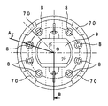
次に、図2及び図3を用いて、挿入部2の構成を説明する。図2は、挿入部2の円筒形状の先端部11を先端側から見たときの正面図である。また、図3は図2のA−O−B線に沿った挿入部2の断面図である。図2に示すように、挿入部2の先端部11の先端面には、その中心に対物レンズ9が配置され、対物レンズ9の外周を囲むように複数のLED照明部8がリング状に配置されている。複数の対物レンズ9は、図3に示すように、第一の対物枠61と第二の対物枠62によって保持されており、第二の対物枠62の基端側に配置されたCCD10とともに対物ユニット63を構成している。CCD10の基端側からは複合同軸ケーブル28と複合同軸ケーブル29から構成される信号線64が延出されている。対物ユニット63は、熱伝導率の高い材質で作られた略円筒形のLED受け65に内挿されている。LED受け65の先端側にはLED照明部8が配置されている。LED照明部8の先端側には透明封止剤66が配置されており、防水密閉されている。LED受け65とLED照明部8との接合面は、熱伝導を効率よく行うために、シリコングリスなどの熱伝導剤が塗布されている。また、LED受け65の外周の一部には、凹状の切り欠き部67が長手方向に設けられており、切り欠き部67の内部に温度センサ12を有する温度センサユニット68が配置されている。LED照明部8及び温度センサユニット68の構成については、後に詳述する。   Next, the structure of the insertion part 2 is demonstrated using FIG.2 and FIG.3. FIG. 2 is a front view when the cylindrical distal end portion 11 of the insertion portion 2 is viewed from the distal end side. FIG. 3 is a cross-sectional view of the insertion portion 2 taken along the line AOB in FIG. As shown in FIG. 2, an objective lens 9 is arranged at the center of the distal end surface of the distal end portion 11 of the insertion portion 2, and a plurality of LED illumination portions 8 are arranged in a ring shape so as to surround the outer periphery of the objective lens 9. Has been. As shown in FIG. 3, the plurality of objective lenses 9 are held by a first objective frame 61 and a second objective frame 62, and together with the CCD 10 disposed on the base end side of the second objective frame 62, A unit 63 is configured. A signal line 64 including a composite coaxial cable 28 and a composite coaxial cable 29 is extended from the base end side of the CCD 10. The objective unit 63 is inserted into a substantially cylindrical LED receiver 65 made of a material having high thermal conductivity. An LED illumination unit 8 is disposed on the tip side of the LED receiver 65. A transparent sealant 66 is disposed on the front end side of the LED illumination unit 8 and is waterproof and sealed. The bonding surface between the LED receiver 65 and the LED illumination unit 8 is coated with a thermal conductive agent such as silicon grease in order to efficiently conduct heat. A concave notch 67 is provided in the longitudinal direction on a part of the outer periphery of the LED receiver 65, and a temperature sensor unit 68 having the temperature sensor 12 is disposed inside the notch 67. The configurations of the LED illumination unit 8 and the temperature sensor unit 68 will be described in detail later.

図2に示すように、先端部11の先端側の外周に配置されている円筒部材69には、先端部11の先端側端部に、内径側への突起部70が4箇所設けられている。図4は円筒部材11の突起部70の先端の形状を説明する斜視図である。突起部70は、先端部11の先端側の円周に沿って、均等な間隔で配置されている。   As shown in FIG. 2, the cylindrical member 69 disposed on the outer periphery on the distal end side of the distal end portion 11 is provided with four protrusions 70 on the inner diameter side at the distal end side end portion of the distal end portion 11. . FIG. 4 is a perspective view for explaining the shape of the tip of the protrusion 70 of the cylindrical member 11. The protrusions 70 are arranged at equal intervals along the circumference on the distal end side of the distal end portion 11.

図3に示すように、円筒部材69の内径部には、対物ユニット63と、LED照明部8及び温度センサユニット68を配したLED受け65とが、突起部70に突き当たり嵌め込まれている。また、円筒部材69の内周面の基端側には、メスネジ71を有している。   As shown in FIG. 3, the objective unit 63 and the LED receiver 65 in which the LED illumination unit 8 and the temperature sensor unit 68 are disposed are fitted into the protrusion 70 in the inner diameter portion of the cylindrical member 69. Further, a female screw 71 is provided on the proximal end side of the inner peripheral surface of the cylindrical member 69.

また、先端部11には、環状固定部材74が配置されており、環状固定部材74の先端側の外周面には、先端側の外径部に先端部11の長手方向に沿って並べて配置された第一のオスネジ72と第二のオスネジ73とが配置されている。   In addition, an annular fixing member 74 is arranged at the distal end portion 11, and is arranged on the outer peripheral surface on the distal end side of the annular fixing member 74 side by side along the longitudinal direction of the distal end portion 11 on the outer diameter portion on the distal end side. A first male screw 72 and a second male screw 73 are arranged.

環状固定部材74と円筒部材69とはその一部が重なり合うように配置されている。つまり、環状固定部材74の先端側の一部が円筒部材69の基端側の一部を内包するように配置されており、円筒部材69のメスネジ71対して環状固定部材74の第二のオスネジ73が螺合されて締め込まれることによって両者が接続固定されている。よって、LED照明部8とLED受け65とが密着した状態で円筒部材69に固定される。また、環状固定部材74の第一のオスネジ72が円筒部材69のメスネジ71より先端側に挿入された状態で、第二のオスネジ73とメスネジ71が螺合されて締め込まれており、万が一、第二のオスネジ73とメスネジ71との螺合が外れた場合にも第一のオスネジ72がストッパーとなって円筒部材69が環状固定部材74から外れて脱落するのを防いでいる。   The annular fixing member 74 and the cylindrical member 69 are arranged so that a part thereof overlaps. That is, a part of the front end side of the annular fixing member 74 is disposed so as to include a part of the base end side of the cylindrical member 69, and the second male screw of the annular fixing member 74 is opposed to the female screw 71 of the cylindrical member 69. Both are connected and fixed by screwing 73 and tightening. Therefore, the LED illuminating unit 8 and the LED receiver 65 are fixed to the cylindrical member 69 in a close contact state. Further, the second male screw 73 and the female screw 71 are screwed together and tightened in a state where the first male screw 72 of the annular fixing member 74 is inserted on the distal end side from the female screw 71 of the cylindrical member 69. Even when the second male screw 73 and the female screw 71 are disengaged, the first male screw 72 serves as a stopper to prevent the cylindrical member 69 from coming off the annular fixing member 74 and falling off.

このように、対物ユニット63等を内径部に配置している円筒部材69と環状固定部材74とが一体となって、先端部11を形成している。先端部11は、その基端側に配した連結部材75を介して湾曲部76と連結されている。   In this manner, the cylindrical member 69 and the annular fixing member 74 in which the objective unit 63 and the like are arranged in the inner diameter portion are integrated to form the distal end portion 11. The distal end portion 11 is connected to the bending portion 76 via a connecting member 75 disposed on the proximal end side.

湾曲部76は、複数の湾曲コマ77を連接して構成されており、湾曲コマ77と接続されたワイヤー52が図示しないジョイスティックによって操作されることによって上下左右自在の方向に湾曲動作される。連結コマ77の外周は湾曲ゴム78が配置されており、湾曲ゴム78の外周は外ブレード79によって覆われている。外ブレード79は、その端部を湾曲ゴム78より先端部11側に突き出して形成されている。湾曲ゴム78の先端部11側の外周には糸縛り80を有しており、また、外ブレード79の先端部11側の湾曲ゴム78よりも突き出して形成された部分には糸縛り81を有しており、これらによって湾曲部76は連結部材75に固定されている。湾曲部76の基端側には図示しない可撓管が連結されている。このように、先端部11と、連結部材75と、湾曲部76と、図示しない可撓管とが一体となって、挿入部2を形成している。   The bending portion 76 is configured by connecting a plurality of bending pieces 77, and is bent in the direction of up / down / left / right by operating the wire 52 connected to the bending pieces 77 with a joystick (not shown). A curved rubber 78 is disposed on the outer periphery of the connecting piece 77, and the outer periphery of the curved rubber 78 is covered with an outer blade 79. The outer blade 79 is formed such that its end protrudes from the curved rubber 78 toward the tip 11. The curved rubber 78 has a thread binding 80 on the outer periphery of the distal end portion 11 side, and the outer blade 79 has a thread binding 81 at a portion protruding from the curved rubber 78 on the distal end portion 11 side. Accordingly, the bending portion 76 is fixed to the connecting member 75. A flexible tube (not shown) is connected to the proximal end side of the bending portion 76. As described above, the distal end portion 11, the connecting member 75, the bending portion 76, and the flexible tube (not shown) are integrated to form the insertion portion 2.

次に、図5乃至図8を用いて、温度センサユニット68の構成を説明する。図5は、図3のC−C線に沿った先端部11の断面図である。図6は、温度センサユニット68を構成する温度センサ基板82を組み立てる前に温度センサユニット68を上面から見た概略図であり、図7は、完成した温度センサユニット68の上面図である。また、図8は温度センサユニット68の側面図である。   Next, the configuration of the temperature sensor unit 68 will be described with reference to FIGS. FIG. 5 is a cross-sectional view of the distal end portion 11 taken along line CC in FIG. FIG. 6 is a schematic view of the temperature sensor unit 68 as viewed from the top before assembling the temperature sensor substrate 82 constituting the temperature sensor unit 68, and FIG. 7 is a top view of the completed temperature sensor unit 68. FIG. 8 is a side view of the temperature sensor unit 68.

図5に示すように、LED受け65の外径側に長手方向に形成された切り欠き部67には、円筒形の先端部11の中心軸と平行な面に接して温度センサユニット68が配置されている。本実施の形態においては切り欠き部67の隙間は空洞であるが、熱伝導率の高いシリコン充填剤などの充填剤で埋めても良い。また、LED受け65の内径側には、長手方向に切り欠き部83が二箇所形成されており、LED照明部8を構成しておりLED照明部8に電源を供給するケーブル25が挿通されている。   As shown in FIG. 5, a temperature sensor unit 68 is disposed in a notch 67 formed in the longitudinal direction on the outer diameter side of the LED receiver 65 in contact with a surface parallel to the central axis of the cylindrical tip 11. Has been. In the present embodiment, the gap of the notch 67 is a cavity, but may be filled with a filler such as a silicon filler having a high thermal conductivity. In addition, two cutouts 83 are formed in the longitudinal direction on the inner diameter side of the LED receiver 65, and the cable 25 for supplying power to the LED illumination unit 8 is inserted through the LED illumination unit 8. Yes.

温度センサユニット68は、図6に示すように、導電パターンを表面に配したフレキシブルな基板である温度センサ基板82と、温度センサ基板82の上面に半田付けされて実装されたサーミスタなどの温度センサ12と、温度センサ12から延出され温度センサ基板82の上面に一部が半田付けされて実装された2本のケーブル37とから構成されている。切り欠き部67に配置される際には、図7及び図8に示すように、温度センサ12とケーブル37が半田付けされて実装されている部分が内包されるように、温度センサ基板82が二つ折りにされる。温度センサ12とケーブル37とが温度センサ基板82に接着している半田の上面を、二つ折りにした温度センサ基板82で覆うことで、先端部11を構成している他のユニットの金属などと半田が接触することによるショートを防ぐことができる。   As shown in FIG. 6, the temperature sensor unit 68 includes a temperature sensor substrate 82 which is a flexible substrate having a conductive pattern on the surface, and a temperature sensor such as a thermistor mounted on the upper surface of the temperature sensor substrate 82 by soldering. 12 and two cables 37 that are extended from the temperature sensor 12 and partially soldered to the upper surface of the temperature sensor substrate 82. As shown in FIGS. 7 and 8, when the temperature sensor substrate 82 is disposed in the notch 67, the temperature sensor substrate 82 is placed so that the portion where the temperature sensor 12 and the cable 37 are soldered and mounted is included. Folded in half. By covering the upper surface of the solder where the temperature sensor 12 and the cable 37 are bonded to the temperature sensor substrate 82 with the temperature sensor substrate 82 folded in half, the metal of other units constituting the tip 11 and the like A short circuit due to contact of solder can be prevented.

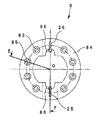
次に図9と図10を用いてLED照明部8の構成を説明する。図9は、図3のD−D線に沿った先端部11の断面図である。また、図10は、図9のE−O−F線に沿ったLED照明部8の断面図である。LED照明部8は、複数のLEDチップ83と、表面に図示しない導電パターンを配しておりLEDチップ83が取り付けられているLED基板84と、LED基板84の図示しない導電パターンに半田付けされてLEDチップ83に電源を供給するケーブル25から構成されている。本実施の形態においては、LED照明部8は8個のLEDチップ83を有しているが、一例であって8個に限定されるものではない。   Next, the structure of the LED illumination part 8 is demonstrated using FIG. 9 and FIG. FIG. 9 is a cross-sectional view of the distal end portion 11 taken along line DD in FIG. Moreover, FIG. 10 is sectional drawing of the LED illumination part 8 along the EOF line of FIG. The LED illumination unit 8 is soldered to a plurality of LED chips 83, an LED board 84 on which a conductive pattern (not shown) is arranged on the surface, and an LED board 84 to which the LED chip 83 is attached, and a conductive pattern (not shown) of the LED board 84 The cable 25 is configured to supply power to the LED chip 83. In the present embodiment, the LED illumination unit 8 has eight LED chips 83, but is an example and is not limited to eight.

図9に示すように、LED基板84はリング状の形状をしており、外径形状は円形に、内径形状は小判型に形成されている。内径に形成された小判型の穴は、LED基板84をLED受け65に取り付ける際に回転止めとして機能している。LED基板84の表面には、円周状に8個のザグリ穴85が設けられており、各ザグリ穴85の内部にLEDチップ83が一個ずつ配置されている。LED基板84には内径側に切り欠き部86が二箇所形成されており、二本のケーブル25がそれぞれの切り欠き部86に内挿されている。LEDチップ83の前面は封止剤87で覆われている。尚、LEDチップ83からはリード線が延出しているが、図示していない。また、LED基板84の表面の配線パターンなども図示していない。   As shown in FIG. 9, the LED substrate 84 has a ring shape, and the outer diameter shape is circular and the inner diameter shape is oval. The oval hole formed in the inner diameter functions as a rotation stopper when the LED substrate 84 is attached to the LED receiver 65. Eight counterbore holes 85 are provided on the surface of the LED board 84 in a circumferential shape, and one LED chip 83 is disposed inside each counterbore hole 85. Two notches 86 are formed on the inner diameter side of the LED substrate 84, and two cables 25 are inserted into the respective notches 86. The front surface of the LED chip 83 is covered with a sealant 87. A lead wire extends from the LED chip 83 but is not shown. Further, the wiring pattern on the surface of the LED substrate 84 is not shown.

上述のように構成した電子内視鏡装置1の作用について、図11に示すフローチャートを用いて説明する。図11は、本発明の第1の実施の形態に係わる最大露光時間の自動制御に関するフローチャートである。   The operation of the electronic endoscope apparatus 1 configured as described above will be described with reference to the flowchart shown in FIG. FIG. 11 is a flowchart relating to the automatic control of the maximum exposure time according to the first embodiment of the present invention.

まず、ステップ101において電子内視鏡装置1の電源がON状態にされると、ステップ103において電子内視鏡装置1のシステムが起動し、観察部位の通常の観察が開始される。引き続きステップ105において先端部11周辺の温度が温度センサ12により検出され、検出された温度は温度センサ処理部19にて電圧値へと変換される。変換された電圧値はシステム制御部24に送信される。次に、例えばスイッチなどの第二のユーザインターフェース22を操作することによりユーザが長時間露光モードで観察を行うように設定することができるので、ステップ107において、ユーザが長時間露光モードを選択したか否かが判定される。   First, when the power source of the electronic endoscope apparatus 1 is turned on in step 101, the system of the electronic endoscope apparatus 1 is activated in step 103, and normal observation of the observation site is started. Subsequently, in step 105, the temperature around the tip 11 is detected by the temperature sensor 12, and the detected temperature is converted into a voltage value by the temperature sensor processing unit 19. The converted voltage value is transmitted to the system control unit 24. Next, since the user can set to perform observation in the long exposure mode by operating the second user interface 22 such as a switch, for example, in step 107, the user selects the long exposure mode. It is determined whether or not.

長時間露光モードは、長時間露光制限モードと、長時間露光通常モードと、長時間露光高感度モードの三つの露光モードから構成されており、先端部11の温度により露光モードが自動的に選択される。ステップ105において、先端部11の温度は電圧値に変換されているので、従って、露光モードは変換された電圧値に基づいて自動的に選択されることになる。図12は、変換された電圧値と露光モードとの関係を説明する図である。図12に示すように、変換された電圧値が閾値V以上、すなわち先端部11の温度が高温である場合は長時間露光制限モードが選択される。変換された電圧値が閾値Vより高く、かつ閾値V未満、すなわち先端部11の温度が中温である場合は長時間露光通常モードが選択される。変換された電圧値が閾値V以下、すなわち先端部11の温度が低温である場合は長時間露光高感度モードが選択される。尚、閾値Vと閾値Vは、ユーザあるいはシステムによって予め設定された任意の電圧値である。 The long exposure mode is composed of three exposure modes: a long exposure limit mode, a long exposure normal mode, and a long exposure high sensitivity mode. The exposure mode is automatically selected according to the temperature of the tip 11. Is done. In step 105, the temperature of the tip 11 has been converted to a voltage value, and therefore the exposure mode is automatically selected based on the converted voltage value. FIG. 12 is a diagram for explaining the relationship between the converted voltage value and the exposure mode. As shown in FIG. 12, the converted voltage value threshold V a or more, that long exposure limit mode when the temperature is higher in the distal end portion 11 is selected. When the converted voltage value is higher than the threshold value V b and lower than the threshold value V a , that is, when the temperature of the tip 11 is an intermediate temperature, the long exposure normal mode is selected. When the converted voltage value is equal to or lower than the threshold value Vb , that is, when the temperature of the tip 11 is low, the long exposure high sensitivity mode is selected. The threshold value V a and the threshold V b is any voltage value which is preset by the user or system.

長時間露光モードでは、LED照明部8から観察部位に対し、設定された最大露光時間まで照明光が照射される。長時間露光モードを構成している三つの露光モードでは、それぞれ最大露光時間が異なって設定されている。表1に各露光モードにおける最大露光時間を示す。

Figure 0004716670
In the long exposure mode, the illumination light is irradiated from the LED illumination unit 8 to the observation site until the set maximum exposure time. In the three exposure modes constituting the long exposure mode, the maximum exposure time is set differently. Table 1 shows the maximum exposure time in each exposure mode.
Figure 0004716670

表1に示すように、先端部11の温度が高温であって長時間露光制限モードが選択された場合、最大露光時間は1/120秒に設定される。先端部11の温度が中温であって長時間露光通常モードが選択された場合、最大露光時間は1/60秒に設定される。先端部11の温度が低温であって長時間露光高感度モードが選択された場合、最大露光時間は1秒に設定される。すなわち、先端部11の温度が高温になるほど最大露光時間が短くなるように、最大露光時間が三段階に設定されていることになる。   As shown in Table 1, when the temperature of the tip 11 is high and the long exposure limit mode is selected, the maximum exposure time is set to 1/120 seconds. When the temperature of the tip 11 is medium and the long exposure normal mode is selected, the maximum exposure time is set to 1/60 seconds. When the temperature of the tip 11 is low and the long exposure high sensitivity mode is selected, the maximum exposure time is set to 1 second. That is, the maximum exposure time is set in three stages so that the maximum exposure time becomes shorter as the temperature of the tip portion 11 becomes higher.

ステップ107において長時間露光モードに設定された場合、第二のユーザインターフェース22から長時間露光モードが選択された旨を伝達する信号がシステム制御部24へ送信され、ステップ109に進む。ステップ107において長時間露光モードが選択されなかった場合、ステップ105へ戻って先端部11周辺の温度が温度センサ12で監視されながら通常の観察が続けられる。   When the long exposure mode is set in step 107, a signal indicating that the long exposure mode is selected is transmitted from the second user interface 22 to the system control unit 24, and the process proceeds to step 109. If the long exposure mode is not selected in step 107, the process returns to step 105, and normal observation is continued while the temperature around the tip 11 is monitored by the temperature sensor 12.

ステップ109において、システム制御部24では、設定された閾値Vと、変換された電圧値とが比較される。変換された電圧値が閾値V以上である場合、ステップ110に進み、システム制御部24は画像処理部17に対して長時間露光制限モードに設定する旨の信号を送信し、画像処理部17は信号を受信すると遅滞なくCCD駆動部16に対し、同様の信号を送信する。CCD駆動部16は信号を受信すると長時間露光制限モードに切り替わり、CCD10を駆動させる。各ユニットが長時間露光制限モードに切り替わり、CCD10が駆動されると引き続きステップ105へ戻って先端部11周辺の温度が温度センサ12で監視されながら長時間露光モードでの観察が続けられる。 In step 109, the system control unit 24, a threshold V a that has been set, the converted voltage value is compared. If converted voltage value is the threshold value V a or more, the process proceeds to step 110, the system control unit 24 transmits a signal indicating the set to long exposure limit mode to the image processing unit 17, an image processing unit 17 When the signal is received, the same signal is transmitted to the CCD drive unit 16 without delay. When the CCD driving unit 16 receives the signal, the CCD driving unit 16 switches to the long exposure limit mode and drives the CCD 10. When each unit is switched to the long exposure limit mode and the CCD 10 is driven, the process returns to step 105 and the observation in the long exposure mode is continued while the temperature around the tip 11 is monitored by the temperature sensor 12.

ステップ109において、変換された電圧値が閾値V未満である場合、ステップ111に進み、設定された閾値Vと変換された電圧値とがシステム制御部24で比較される。変換された電圧値が閾値V以下である場合、ステップ112に進み、システム制御部24は画像処理部17に対して長時間露光高感度モードに設定する旨の信号を送信し、画像処理部17は信号を受信すると遅滞なくCCD駆動部16に対し、長時間露光高感度モードに設定する旨の信号を送信する。CCD駆動部16は信号を受信すると長時間露光高感度モードに切り替わり、CCD10を駆動させる。各ユニットが長時間露光高感度モードに切り替わり、CCD10が駆動されると引き続きステップ105へ戻って先端部11周辺の温度が温度センサ12で監視されながら長時間露光モードでの観察が続けられる。 In step 109, the converted voltage value is less than the threshold value V a, the process proceeds to step 111, and the converted voltage value with the preset threshold value V b is compared by the system control unit 24. If the converted voltage value is less than or equal to the threshold value Vb , the process proceeds to step 112, where the system control unit 24 transmits a signal to the image processing unit 17 to set the long exposure high sensitivity mode, and the image processing unit When the signal 17 is received, a signal for setting the long exposure high sensitivity mode is transmitted to the CCD drive unit 16 without delay. When the CCD driver 16 receives the signal, it switches to the long exposure high sensitivity mode and drives the CCD 10. When each unit is switched to the long exposure high sensitivity mode and the CCD 10 is driven, the process returns to step 105 and the observation in the long exposure mode is continued while the temperature around the tip 11 is monitored by the temperature sensor 12.

ステップ111において、変換された電圧値が閾値Vより高い場合、ステップ113に進み、システム制御部24は画像処理部17に対して長時間露光通常モードに設定する旨の信号を送信し、画像処理部17は信号を受信すると遅滞なくCCD駆動部16に対し、長時間露光通常モードに設定する旨の信号を送信する。CCD駆動部16は信号を受信すると長時間露光通常モードに切り替わり、CCD10を駆動させる。各ユニットが長時間露光通常モードに切り替わり、CCD10が駆動されると引き続きステップ105へ戻って先端部11周辺の温度が温度センサ12で監視されながら長時間露光モードでの観察が続けられる。 In step 111, if the converted voltage value is higher than the threshold value Vb , the process proceeds to step 113, where the system control unit 24 sends a signal to the image processing unit 17 to set the long exposure normal mode, and When the processing unit 17 receives the signal, the processing unit 17 transmits a signal indicating that the long exposure normal mode is set to the CCD driving unit 16 without delay. When the CCD driving unit 16 receives the signal, it switches to the long exposure normal mode and drives the CCD 10. When each unit is switched to the long exposure normal mode and the CCD 10 is driven, the process returns to step 105 and the observation in the long exposure mode is continued while the temperature around the tip 11 is monitored by the temperature sensor 12.

すなわち、ステップ107において長時間露光モードに設定された場合、ステップ109とステップ111の二段階のステップにより先端部11周辺の温度に対応した露光モードの選択がなされる。先端部11周辺の温度が高温の場合には長時間露光制限モードが、先端部11周辺の温度が中温の場合には長時間露光通常モードが、先端部11周辺の温度が低温の場合には長時間露光高感度モードが選択され、選択されたモードに従って最大露光時間が自動的に設定される。どの露光モードが選択された場合においても、露光モードが選択されて観察が開始されると、直ちにステップ105に戻って先端部11周辺の温度を監視する。よって、先端部11周辺の温度が変化した場合には、露光モードも温度変化に追随して適切な露光モードが選択される。   That is, when the long exposure mode is set in step 107, the exposure mode corresponding to the temperature around the tip portion 11 is selected in two steps, step 109 and step 111. When the temperature around the tip 11 is high, the long exposure limit mode is selected, when the temperature around the tip 11 is medium temperature, the long exposure normal mode is set, and when the temperature around the tip 11 is low. The long exposure high sensitivity mode is selected, and the maximum exposure time is automatically set according to the selected mode. Regardless of which exposure mode is selected, when the exposure mode is selected and observation is started, the process immediately returns to step 105 to monitor the temperature around the tip 11. Therefore, when the temperature around the tip portion 11 changes, an appropriate exposure mode is selected following the temperature change.

このように、本実施の形態の電子内視鏡装置では、長時間露光モードが設定された場合、先端部11周辺の温度を常に監視し、高温、中温、低温の三段階の温度域に対応した露光モードのうちの一つが選択されることにより、露光モード毎に定義されている先端部11周辺の温度に応じた最大露光時間が自動的に設定されるので、CCD10の温度上昇を抑制して観察画像のノイズを防ぐことができ、画像の観察性が向上する。最大露光時間は、システムにより監視されている先端部11周辺の温度に基づき自動的に設定されるため、ユーザが最大露光時間を設定する手間を省くことができ、操作性が向上する。   As described above, in the electronic endoscope apparatus according to the present embodiment, when the long exposure mode is set, the temperature around the distal end portion 11 is constantly monitored, and the three temperature ranges of high temperature, medium temperature, and low temperature are supported. By selecting one of the exposure modes, the maximum exposure time corresponding to the temperature around the tip 11 defined for each exposure mode is automatically set, so that the temperature rise of the CCD 10 is suppressed. Thus, noise in the observed image can be prevented, and the observability of the image is improved. Since the maximum exposure time is automatically set based on the temperature around the tip 11 monitored by the system, it is possible to save the user from setting the maximum exposure time and improve operability.

尚、本実施の形態の電子内視鏡装置1は、第一のユーザインターフェース13と第二のユーザインターフェース22の二つのユーザインターフェースを有しているが、互いの機能を入れ替えて構成してもよい。例えば、第二のユーザインターフェース22で長時間露光モードでの観察を設定するのではなく、第一のユーザインターフェース13で設定するように構成してもよい。また、第一のユーザインターフェース13と第二のユーザインターフェース22の機能を統合して一つのユーザインターフェースとして構成してもよい。更に、統合されたユーザインターフェースを三つ以上のユーザインターフェースに分割して機能を分散させて構成してもよい。   The electronic endoscope apparatus 1 according to the present embodiment has two user interfaces, ie, a first user interface 13 and a second user interface 22, but may be configured by exchanging their functions. Good. For example, instead of setting the observation in the long exposure mode with the second user interface 22, the setting may be made with the first user interface 13. Further, the functions of the first user interface 13 and the second user interface 22 may be integrated to constitute a single user interface. Further, the integrated user interface may be divided into three or more user interfaces to distribute the functions.

また、表示装置7には観察画像だけでなく、図13に示すように、選択された長時間露光モードや最大露光時間などを表示してもよい。図13は表示装置7に出画された画像の一例を示した概略図である。同様に、記録再生部18において観察画像を記録する場合にも、選択された長時間露光モードや最大露光時間などを記録してもよい。観察画像の他に表示または記録されるのは、長時間露光モードと最大露光時間の両方である必要はなく、長時間露光モードのみでもよいし、最大露光時間のみでもよい。   Further, not only the observation image but also the selected long exposure mode and the maximum exposure time may be displayed on the display device 7 as shown in FIG. FIG. 13 is a schematic diagram illustrating an example of an image output on the display device 7. Similarly, when an observation image is recorded in the recording / reproducing unit 18, the selected long exposure mode, maximum exposure time, and the like may be recorded. It is not necessary for both the long exposure mode and the maximum exposure time to be displayed or recorded in addition to the observation image, and only the long exposure mode or only the maximum exposure time may be displayed.

(第2の実施の形態)
次に、本発明の第2の実施の形態を説明する。電子内視鏡装置1の構成は第1の実施の形態と同じであるため、ここでは特徴となる電子内視鏡装置1の作用についてのみ説明する。
(Second Embodiment)
Next, a second embodiment of the present invention will be described. Since the configuration of the electronic endoscope apparatus 1 is the same as that of the first embodiment, only the operation of the characteristic electronic endoscope apparatus 1 will be described here.

図14は本発明の第2の実施の形態に係わる露光時間の自動制御に関するフローチャートである。図14に示すように、まず、ステップ201において電子内視鏡装置1の電源がON状態にされると、ステップ203において電子内視鏡装置1のシステムが起動し、観察部位の通常の観察が開始される。引き続きステップ205において先端部11周辺の温度が温度センサ12により監視され、検出された温度は温度センサ処理部19にて電圧値へと変換される。変換された電圧値はシステム制御部24に送信される。次に、例えばスイッチなどの第二のユーザインターフェース22を操作することによりユーザが長時間露光モードで観察を行うように設定することができるので、ステップ207において、ユーザが長時間露光モードを選択したか否かが判定される。   FIG. 14 is a flowchart relating to automatic control of the exposure time according to the second embodiment of the present invention. As shown in FIG. 14, first, when the power of the electronic endoscope apparatus 1 is turned on in step 201, the system of the electronic endoscope apparatus 1 is activated in step 203, and normal observation of the observation site is performed. Be started. Subsequently, in step 205, the temperature around the tip 11 is monitored by the temperature sensor 12, and the detected temperature is converted into a voltage value by the temperature sensor processing unit 19. The converted voltage value is transmitted to the system control unit 24. Next, since the user can set to perform observation in the long exposure mode by operating the second user interface 22 such as a switch, for example, the user selects the long exposure mode in Step 207. It is determined whether or not.

長時間露光モードは、第1の実施の形態と同様、長時間露光制限モードと、長時間露光通常モードと、長時間露光高感度モードの三つの露光モードから構成されており、先端部11の温度により露光モードが自動的に選択される。変換された電圧値と露光モードとの関係も第1の実施の形態と同様である。すなわち、図12に示すように、変換された電圧値が閾値V以上、すなわち先端部11の温度が高温である場合は長時間露光制限モードが選択される。変換された電圧値が閾値Vより高く、かつ閾値V未満、すなわち先端部11の温度が中温である場合は長時間露光通常モードが選択される。変換された電圧値が閾値V以下、すなわち先端部11の温度が低温である場合は長時間露光高感度モードが選択される。尚、閾値Vと閾値Vは、ユーザあるいはシステムによって予め設定された任意の電圧値である。 As in the first embodiment, the long exposure mode is composed of three exposure modes: a long exposure limit mode, a long exposure normal mode, and a long exposure high sensitivity mode. The exposure mode is automatically selected according to the temperature. The relationship between the converted voltage value and the exposure mode is the same as that in the first embodiment. That is, as shown in FIG. 12, the converted voltage value threshold V a or more, that is long-time exposure limit mode when the temperature is higher in the distal end portion 11 is selected. When the converted voltage value is higher than the threshold value V b and lower than the threshold value V a , that is, when the temperature of the tip 11 is an intermediate temperature, the long exposure normal mode is selected. When the converted voltage value is equal to or lower than the threshold value Vb , that is, when the temperature of the tip 11 is low, the long exposure high sensitivity mode is selected. The threshold value V a and the threshold V b is any voltage value which is preset by the user or system.

長時間露光モードでは、LED照明部8から観察部位に対し、設定された最大露光時間まで照明光が照射される。長時間露光モードを構成している三つの露光モードでは、それぞれ最大露光時間が異なって設定されている。表2に各露光モードにおける最大露光時間を示す。

Figure 0004716670
In the long exposure mode, the illumination light is irradiated from the LED illumination unit 8 to the observation site until the set maximum exposure time. In the three exposure modes constituting the long exposure mode, the maximum exposure time is set differently. Table 2 shows the maximum exposure time in each exposure mode.
Figure 0004716670

表2に示すように、先端部11の温度が高温であって長時間露光制限モードが選択された場合、最大露光時間は、変換された電圧値に対応した温度テーブルAを参照して設定される。図15は長時間露光制限モードにおける変換された電圧値とテーブルデータとの対応関係を示す図である。また、表3に長時間露光制限モードにおける温度テーブルAの例を示す。

Figure 0004716670
As shown in Table 2, when the temperature of the tip 11 is high and the long exposure limit mode is selected, the maximum exposure time is set with reference to the temperature table A corresponding to the converted voltage value. The FIG. 15 is a diagram showing a correspondence relationship between the converted voltage value and the table data in the long exposure limit mode. Table 3 shows an example of the temperature table A in the long exposure limit mode.
Figure 0004716670

長時間露光制限モードでは、閾値Vより高く設定された閾値Va1から閾値Van(nは1より大きい自然数)のn個の閾値を有しており、表3に示すように、温度テーブルAはn個の閾値によってn+1個のテーブルデータに分けられている。 In the long exposure limit mode, the threshold value V a1 to the threshold value V an (n is a natural number greater than 1) set higher than the threshold value V a have n threshold values. A is divided into n + 1 table data by n threshold values.

変換された電圧値が閾値V以上閾値Va1未満の場合、最大露光時間が1/70秒に設定されたテーブルデータAが選択される。変換された電圧値が閾値Va1以上閾値Va2未満の場合、最大露光時間が1/80秒に設定されたテーブルデータAが選択される。変換された電圧値が閾値Va(n−1)以上閾値Van未満の場合、最大露光時間が1/110秒に設定されたテーブルデータAが選択される。変換された電圧値が閾値Van以上の場合、最大露光時間が1/120秒に設定されたテーブデータルAn+1が選択される。変換された電圧値が閾値Va2以上Va(n−1)未満の場合も同様に、変換された電圧値に従って、閾値が高いほど最大露光時間が短くなるように設定されたテーブルデータAからテーブルデータAn−1のうち該当するテーブルデータが選択される。 If converted voltage value is less than the threshold V a higher threshold V a1, table data A 1 to the maximum exposure time is set to 1/70 seconds is selected. If converted voltage value is less than the threshold V a1 or larger than the threshold V a2, table data A 2 which maximum exposure time is set to 1/80 seconds is selected. If converted voltage value is less than the threshold V a (n-1) than the threshold value V an,, the maximum exposure time is set table data A n to 1/110 seconds is selected. If converted voltage value is equal to or more than the threshold V an,, table data Le A n + 1 that maximum exposure time is set to 1/120 seconds is selected. Similarly, when the converted voltage value is greater than or equal to the threshold value V a2 and less than V a (n−1), the table data A 3 is set such that the maximum exposure time is shortened as the threshold value increases according to the converted voltage value. The corresponding table data is selected from the table data An-1 .

表2に示すように、先端部11の温度が中温であって長時間露光通常モードが選択された場合、最大露光時間は1/60秒に設定される。   As shown in Table 2, when the temperature of the tip 11 is medium and the long exposure normal mode is selected, the maximum exposure time is set to 1/60 seconds.

先端部11の温度が低温であって長時間露光高感度モードが選択された場合、最大露光時間は、変換された電圧値に対応した温度テーブルBを参照して設定される。図16は、長時間露光高感度モードにおける変換された電圧値とテーブルデータとの関係を示す図である。また、表4に長時間高感度モードにおける温度テーブルBの例を示す。

Figure 0004716670
When the temperature of the tip 11 is low and the long exposure high sensitivity mode is selected, the maximum exposure time is set with reference to the temperature table B corresponding to the converted voltage value. FIG. 16 is a diagram showing the relationship between the converted voltage value and table data in the long exposure high sensitivity mode. Table 4 shows an example of the temperature table B in the long-time high sensitivity mode.
Figure 0004716670

長時間露光高感度モードでは、閾値Vより低く設定された閾値Vb1から閾値Vbm(mは1より大きい自然数)のm個の閾値を有しており、表4に示すように、温度テーブルBはm個の閾値によってm+1個のテーブルデータに分けられている。 In the long exposure high sensitivity mode, the threshold value V b1 to the threshold value V bm (m is a natural number greater than 1) set lower than the threshold value V b has m threshold values. Table B is divided into m + 1 table data by m threshold values.

変換された電圧値が閾値Vb1より高く閾値V以下の場合、最大露光時間が1/50秒に設定されたテーブルデータBが選択される。変換された電圧値が閾値Vb2より高く閾値Vb1以下の場合、最大露光時間が1/40秒に設定されたテーブルデータBが選択される。変換された電圧値が閾値Vbmより高く閾値Vb(m−1)以下の場合、最大露光時間が1/10秒に設定されたテーブルデータBが選択される。変換された電圧値が閾値Vbm以下の場合、最大露光時間が1秒に設定されたテーブルデータBm+1が選択される。変換された電圧値が閾値Vb(m−1)より高くV以下の場合も同様に、変換された電圧値に従って、閾値が低いほど最大露光時間が長くなるように設定されたテーブルデータBからテーブルデータBm−1のうち該当するテーブルデータが選択される。 If converted voltage value is higher than the threshold V b than the threshold value V b1, the table data B 1 to the maximum exposure time is set to 1/50 seconds is selected. If converted voltage value of the high threshold V b1 or less than the threshold V b2, table data B 2 the maximum exposure time is set to 1/40 seconds is selected. When the converted voltage value is higher than the threshold value V bm and equal to or lower than the threshold value V b (m−1), the table data B m in which the maximum exposure time is set to 1/10 second is selected. When the converted voltage value is equal to or less than the threshold value V bm, the table data B m + 1 in which the maximum exposure time is set to 1 second is selected. Similarly, when the converted voltage value of the high V 2 less than the threshold V b (m-1), converted in accordance with the voltage value, the set table data B so that the maximum exposure time becomes longer as the threshold is lower 3, the corresponding table data is selected from the table data B m−1 .

すなわち、先端部11の温度が高温になるほど最大露光時間が短くなるように、長時間露光制限モードではn+1段階に、長時間露光通常モードでは1段階に、長時間露光高感度モードではm+1段階に、それぞれ露光時間が設定されていることになる。   That is, the maximum exposure time becomes shorter as the temperature of the tip 11 becomes higher, so that it is n + 1 steps in the long exposure limit mode, one step in the long exposure normal mode, and m + 1 step in the long exposure high sensitivity mode. The exposure time is set for each.

ステップ207において長時間露光モードに設定された場合、第二のユーザインターフェース22から長時間露光モードが選択された旨を伝達する信号がシステム制御部24へ送信され、ステップ209に進む。ステップ207において長時間露光モードが選択されなかった場合、ステップ205へ戻って先端部11周辺の温度が温度センサ12で監視されながら通常の観察が続けられる。   If the long exposure mode is set in step 207, a signal indicating that the long exposure mode has been selected is transmitted from the second user interface 22 to the system control unit 24, and the process proceeds to step 209. If the long exposure mode is not selected in step 207, the process returns to step 205 and normal observation is continued while the temperature around the tip 11 is monitored by the temperature sensor 12.

ステップ209において、システム制御部24では、設定された閾値Vと、ステップ203において温度センサ処理部19から受信した変換された電圧値とが比較される。変換された電圧値が閾値V以上である場合、長時間露光制限モードが選択され、引き続きステップ210に進んで温度テーブルを選択する。 In step 209, the system control unit 24, a threshold V a that has been set, and the converted voltage value received from the temperature sensor processing unit 19 in step 203 are compared. If converted voltage value is the threshold value V a above, is long exposure limitation mode is selected and selects the temperature table continues to a step 210.

図17は、ステップ210で行われる長時間露光制限モードにおける温度テーブルのテーブルデータの選択に関するフローチャートである。図17に示すように、まず、ステップ301においてシステム制御部24は長時間露光制限モードにおける温度テーブルAを選択する。次に、ステップ303において、システム制御部24では、変換された電圧値と閾値Va1とが比較される。変換された電圧値がVa1未満である場合、ステップ304に進み、テーブルデータAが選択される。ステップ303において、変換された電圧値がVa1以上である場合、ステップ305に進み、変換された電圧値と閾値Va2とがシステム制御部24において比較される。変換された電圧値がVa2未満である場合、ステップ306に進み、テーブルデータAが選択される。ステップ305において、変換された電圧値がVa2以上である場合、図示しない次のステップに進んで、変換された電圧値と閾値Va3、・・・閾値Va(n−1)との比較がシステム制御部24において次々と行われ、比較結果に応じてテーブルデータが選択される。変換された電圧値が閾値Va(n−1)以上である場合、ステップ307に進み、変換された電圧値と閾値Vanとがシステム制御部24において比較される。変換された電圧値がVan未満である場合、ステップ308に進み、テーブルデータAが選択される。変換された電圧値がVan以上である場合、ステップ309に進み、テーブルデータAn+1が選択される。 FIG. 17 is a flowchart relating to selection of table data of the temperature table in the long time exposure restriction mode performed in step 210. As shown in FIG. 17, first, in step 301, the system control unit 24 selects the temperature table A in the long exposure restriction mode. Next, in step 303, the system control unit 24 compares the converted voltage value with the threshold value V a1 . If converted voltage value is less than V a1, the process proceeds to step 304, the table data A 1 is selected. If the converted voltage value is equal to or higher than V a1 in step 303, the process proceeds to step 305, where the converted voltage value and the threshold value V a2 are compared in the system control unit 24. If converted voltage value is less than V a2, the process proceeds to step 306, the table data A 2 is selected. In step 305, if the converted voltage value is equal to or higher than V a2 , the process proceeds to the next step (not shown), and the converted voltage value is compared with threshold value V a3 ,..., Threshold value V a (n−1). Are successively performed in the system control unit 24, and table data is selected according to the comparison result. If converted voltage value is the threshold value V a (n-1) or more, the process proceeds to step 307, and the converted voltage value and the threshold value V an, is compared in the system controller 24. If converted voltage value is less than V an,, the process proceeds to step 308, the table data A n is selected. If converted voltage value is V an, or more, the process proceeds to step 309, the table data A n + 1 is selected.

ステップ304、ステップ306、ステップ308、ステップ309、及び図示しないステップにおいてテーブルデータが選択されると、ステップ311に進む。ステップ311では、システム制御部24から画像処理部17に対して、選択されたテーブルデータに設定されている最大露光時間での長時間露光制限モードに設定する旨の信号を送信する。例えば、テーブルデータAが選択されている場合、システム制御部24は画像処理部17に対して、最大露光時間1/70秒の長時間露光制限モードに設定する旨の信号を送信することになる。画像処理部17は信号を受信すると遅滞なくCCD駆動部16に対し、受信した信号と同様の信号を送信する。 When table data is selected in step 304, step 306, step 308, step 309, and a step (not shown), the process proceeds to step 311. In step 311, the system control unit 24 transmits a signal to the image processing unit 17 to set the long exposure limit mode with the maximum exposure time set in the selected table data. For example, when the table data A 1 is selected, the system control unit 24 transmits a signal to the image processing unit 17 to set the long exposure limit mode with the maximum exposure time of 1/70 seconds. Become. When receiving the signal, the image processing unit 17 transmits a signal similar to the received signal to the CCD driving unit 16 without delay.

CCD駆動部16は信号を受信すると、選択された最大露光時間での長時間露光制限モードに切り替わり、CCD10を駆動させる。各ユニットが選択された最大露光時間での長時間露光制限モードに切り替わり、CCD10が駆動されると、ステップ311が終了することによってステップ210も終了し、引き続きステップ205へ戻って先端部11周辺の温度が温度センサ12で監視されながら長時間露光モードでの観察が続けられる。   When the CCD driving unit 16 receives the signal, the CCD driving unit 16 switches to the long exposure limit mode with the selected maximum exposure time, and drives the CCD 10. When each unit is switched to the long exposure limit mode at the selected maximum exposure time and the CCD 10 is driven, step 311 is ended, and step 210 is also ended. Observation in the long exposure mode is continued while the temperature is monitored by the temperature sensor 12.

ステップ209において、変換された電圧値が閾値V未満である場合、ステップ211に進み、設定された閾値Vと変換された電圧値とがシステム制御部24で比較される。変換された電圧値が閾値V以下である場合、長時間露光高感度モードが選択され、引き続きステップ212に進んで温度テーブルBを選択する。 In step 209, the converted voltage value is less than the threshold value V a, the process proceeds to step 211, and the converted voltage value with the preset threshold value V b is compared by the system control unit 24. If the converted voltage value is less than or equal to the threshold value Vb , the long exposure high sensitivity mode is selected, and the process proceeds to step 212 to select the temperature table B.

図18は、ステップ212で行われる長時間露光高感度モードにおける温度テーブルのテーブルデータの選択に関するフローチャートである。図18に示すように、まず、ステップ401においてシステム制御部24は長時間露光高感度モードにおける温度テーブルBを選択する。次に、ステップ403において、システム制御部24では、変換された電圧値と閾値Vb1とが比較される。変換された電圧値がVb1より高い場合、ステップ404に進み、テーブルデータBが選択される。ステップ403において、変換された電圧値がVb1以下である場合、ステップ405に進み、変換された電圧値と閾値Vb2とがシステム制御部24において比較される。変換された電圧値がVb2より高い場合、ステップ406に進み、テーブルデータBが選択される。ステップ405において、変換された電圧値がVb2以下である場合、図示しない次のステップに進んで、変換された電圧値と閾値Vb3、・・・閾値Vb(m−1)との比較がシステム制御部24において次々と行われ、比較結果に応じてテーブルデータが選択される。変換された電圧値が閾値Vb(m−1)以下である場合、ステップ407に進み、変換された電圧値と閾値Vbmとがシステム制御部24において比較される。変換された電圧値がVbmより高い場合、ステップ408に進み、テーブルデータBが選択される。変換された電圧値がVbm以下である場合、ステップ409に進み、テーブルデータBm+1が選択される。 FIG. 18 is a flowchart regarding selection of table data of the temperature table in the long exposure high sensitivity mode performed in step 212. As shown in FIG. 18, first, in step 401, the system control unit 24 selects the temperature table B in the long exposure high sensitivity mode. Next, in step 403, the system control unit 24 compares the converted voltage value with the threshold value Vb1 . If converted voltage value is higher than V b1, the process proceeds to step 404, the table data B 1 is selected. In step 403, the converted voltage value may be V b1 or less, the process proceeds to step 405, the converted voltage value with the threshold V b2 are compared in the system controller 24. If converted voltage value is higher than V b2, the process proceeds to step 406, table data B 2 is selected. In step 405, if the converted voltage value is equal to or less than V b2 , the process proceeds to the next step (not shown), and the converted voltage value is compared with threshold value V b3 ,... Threshold value V b (m−1). Are successively performed in the system control unit 24, and table data is selected according to the comparison result. When the converted voltage value is equal to or smaller than the threshold value V b (m−1) , the process proceeds to step 407, and the converted voltage value and the threshold value V bm are compared in the system control unit 24. If the converted voltage value is higher than V bm , the process proceeds to step 408 and the table data B m is selected. If the converted voltage value is equal to or less than V bm , the process proceeds to step 409 and the table data B m + 1 is selected.

ステップ404、ステップ406、ステップ408、ステップ409、及び図示しないステップにおいて温度テーブルが選択されると、ステップ411に進む。ステップ411では、システム制御部24から画像処理部17に対して、選択されたテーブルデータに設定されている最大露光時間の長時間露光高感度モードに設定する旨の信号を送信する。例えば、テーブルデータBが選択されている場合、システム制御部24は画像処理部17に対して、最大露光時間1/50秒での長時間露光高感度モードに設定する旨の信号を送信することになる。画像処理部17は信号を受信すると遅滞なくCCD駆動部16に対し、受信した信号と同様の信号を送信する。 When the temperature table is selected in step 404, step 406, step 408, step 409, and a step (not shown), the process proceeds to step 411. In step 411, the system control unit 24 transmits a signal to the image processing unit 17 to set the long exposure high sensitivity mode for the maximum exposure time set in the selected table data. For example, when the table data B 1 is selected, the system control unit 24 sends a signal to the image processing unit 17 to set the long exposure high sensitivity mode with the maximum exposure time of 1/50 seconds. It will be. When receiving the signal, the image processing unit 17 transmits a signal similar to the received signal to the CCD driving unit 16 without delay.

CCD駆動部16は信号を受信すると、選択された最大露光時間での長時間露光制限モードに切り替わり、CCD10を駆動させる。各ユニットが選択された最大露光時間での長時間露光制限モードに切り替わり、CCD10が駆動されると、ステップ411が終了することによってステップ212も終了し、引き続きステップ205へ戻って先端部11周辺の温度が温度センサ12で監視されながら長時間露光モードでの観察が続けられる。   When the CCD driving unit 16 receives the signal, the CCD driving unit 16 switches to the long exposure limit mode with the selected maximum exposure time, and drives the CCD 10. When each unit is switched to the long exposure limit mode at the selected maximum exposure time and the CCD 10 is driven, step 411 is completed and step 212 is also ended. Observation in the long exposure mode is continued while the temperature is monitored by the temperature sensor 12.

ステップ211において、変換された電圧値が閾値Vより高い場合、ステップ213に進み、システム制御部24は画像処理部17に対して最大露光時間1/60秒での長時間露光通常モードに設定する旨の信号を送信し、画像処理部17は信号を受信すると遅滞なくCCD駆動部16に対し、最大露光時間1/60秒での長時間露光通常モードに設定する旨の信号を送信する。CCD駆動部16は信号を受信すると最大露光時間1/60秒での長時間露光通常モードに切り替わり、CCD10を駆動させる。各ユニットが最大露光時間1/60秒での長時間露光通常モードに切り替わり、CCD10が駆動されると引き続きステップ205へ戻って先端部11周辺の温度が温度センサ12で監視されながら長時間露光モードでの観察が続けられる。 In step 211, if the converted voltage value is higher than the threshold value Vb , the process proceeds to step 213, and the system control unit 24 sets the long exposure normal mode with the maximum exposure time 1/60 seconds for the image processing unit 17. When the image processing unit 17 receives the signal, the image processing unit 17 transmits a signal to the CCD driving unit 16 to set the long exposure normal mode with the maximum exposure time of 1/60 seconds without delay. When the CCD driver 16 receives the signal, it switches to the long exposure normal mode with a maximum exposure time of 1/60 seconds, and drives the CCD 10. Each unit is switched to the long exposure normal mode with a maximum exposure time of 1/60 seconds. When the CCD 10 is driven, the process returns to step 205 and the temperature sensor 12 monitors the temperature around the tip 11 while the long exposure mode is set. Observations at will continue.

すなわち、ステップ207において長時間露光モードに設定された場合、ステップ209とステップ211の二段階のステップにより先端部11周辺の温度に対応した露光モードの選択がなされる。先端部11周辺の温度が高温の場合には長時間露光制限モードが、先端部11周辺の温度が中温の場合には長時間露光通常モードが、先端部11周辺の温度が低温の場合には長時間露光高感度モードが選択され、選択されたモードに従って最大露光時間が自動的に設定される。また、長時間露光制限モードでは最大露光時間が先端部11周辺の温度に依存して1/70秒から1/120秒の間の値に設定され、長時間露光通常モードでは最大露光時間が1/60秒に設定され、長時間露光高感度モードでは最大露光時間が先端部11周辺の温度に依存して1/50秒から1秒の間に設定される。どの露光モードに選択された場合においても、露光モードが選択されて観察が開始されると、直ちにステップ205に戻って先端部11周辺の温度を監視する。よって、先端部11周辺の温度が変化した場合には、露光モード及び最大露光時間も温度変化に追随して適切な露光モード及び最大露光時間が選択される。   That is, when the long exposure mode is set in step 207, the exposure mode corresponding to the temperature around the tip portion 11 is selected in two steps, step 209 and step 211. When the temperature around the tip 11 is high, the long exposure limit mode is selected, when the temperature around the tip 11 is medium temperature, the long exposure normal mode is set, and when the temperature around the tip 11 is low. The long exposure high sensitivity mode is selected, and the maximum exposure time is automatically set according to the selected mode. In the long exposure limit mode, the maximum exposure time is set to a value between 1/70 seconds and 1/120 seconds depending on the temperature around the tip 11, and in the long exposure normal mode, the maximum exposure time is 1 In the long exposure high sensitivity mode, the maximum exposure time is set between 1/50 second and 1 second depending on the temperature around the tip 11. Regardless of which exposure mode is selected, when the exposure mode is selected and observation is started, the process immediately returns to step 205 to monitor the temperature around the tip 11. Therefore, when the temperature around the tip 11 changes, the exposure mode and the maximum exposure time follow the temperature change, and an appropriate exposure mode and maximum exposure time are selected.

このように、本実施の形態の電子内視鏡装置では、長時間露光モードが設定された場合、先端部11周辺の温度を常に監視し、高温、中温、低温の三段階の温度域に対応した露光モードのうちの一つが選択されることにより、露光モード毎に定義されている先端部11周辺の温度に応じた最大露光時間が自動的に設定される。高温の温度域ではn段階の最大露光時間が、低温の温度域ではm段階の最大露光時間が定義されており、先端部11周辺の微妙な温度変化に追随して最大露光時間が自動的に変更されるため、CCD10の温度上昇を抑制して観察画像のノイズを防ぐことができ、画像の観察性がより一層向上する。最大露光時間は、システムにより監視されている先端部11周辺の温度に基づき自動的に設定されるため、ユーザが設定する手間を省くことができ、操作性が向上する。   As described above, in the electronic endoscope apparatus according to the present embodiment, when the long exposure mode is set, the temperature around the distal end portion 11 is constantly monitored, and the three temperature ranges of high temperature, medium temperature, and low temperature are supported. By selecting one of the exposure modes, the maximum exposure time corresponding to the temperature around the tip 11 defined for each exposure mode is automatically set. A maximum exposure time of n steps is defined in the high temperature range, and a maximum exposure time of m steps is defined in the low temperature range, and the maximum exposure time is automatically tracked following subtle temperature changes around the tip 11. Since the change is made, the temperature rise of the CCD 10 can be suppressed to prevent the noise of the observation image, and the image observability is further improved. Since the maximum exposure time is automatically set based on the temperature around the tip 11 monitored by the system, it is possible to save the user from setting time and improve operability.

尚、本実施の形態の電子内視鏡装置1は、第1の実施の形態と同様に、第一のユーザインターフェース13と第二のユーザインターフェース22の二つのユーザインターフェースを有しているが、互いの機能を入れ替えて構成してもよい。例えば、第二のユーザインターフェース22で長時間露光モードでの観察を設定するのではなく、第一のユーザインターフェース13で設定するように構成してもよい。また、第一のユーザインターフェース13と第二のユーザインターフェース22の機能を統合して一つのユーザインターフェースとして構成してもよい。更に、統合されたユーザインターフェースを三つ以上のユーザインターフェースに分割して機能を分散させて構成してもよい。
また、表示装置7には観察画像だけでなく、図13に示すように、選択された長時間露光モードや最大露光時間などを表示してもよい。図13は表示装置7に出画された画像の一例を示した概略図である。同様に、記録再生部18において観察画像を記録する場合にも、選択された長時間露光モードや最大露光時間などを記録してもよい。観察画像の他に表示または記録されるのは、長時間露光モードと最大露光時間の両方である必要はなく、長時間露光モードのみでもよいし、最大露光時間のみでもよい。
The electronic endoscope apparatus 1 according to the present embodiment has two user interfaces, a first user interface 13 and a second user interface 22, as in the first embodiment. The functions of each other may be interchanged. For example, instead of setting the observation in the long exposure mode with the second user interface 22, the setting may be made with the first user interface 13. Further, the functions of the first user interface 13 and the second user interface 22 may be integrated to constitute a single user interface. Further, the integrated user interface may be divided into three or more user interfaces to distribute the functions.
Further, not only the observation image but also the selected long exposure mode and the maximum exposure time may be displayed on the display device 7 as shown in FIG. FIG. 13 is a schematic diagram illustrating an example of an image output on the display device 7. Similarly, when an observation image is recorded in the recording / reproducing unit 18, the selected long exposure mode, maximum exposure time, and the like may be recorded. It is not necessary for both the long exposure mode and the maximum exposure time to be displayed or recorded in addition to the observation image, and only the long exposure mode or only the maximum exposure time may be displayed.

本発明の第1の実施の形態に係わる電子内視鏡装置の全体構成を概略的に示したブロック図である。1 is a block diagram schematically showing an overall configuration of an electronic endoscope apparatus according to a first embodiment of the present invention. 本発明の第1の実施の形態に係わる挿入部の円筒形状の先端部を先端側から見たときの正面図である。It is a front view when the cylindrical front-end | tip part of the insertion part concerning the 1st Embodiment of this invention is seen from the front end side. 図2のA−O−B線に沿った挿入部の断面図である。It is sectional drawing of the insertion part along the AOB line of FIG. 本発明の第1の実施の形態に係わる円筒部材の突起部の先端の形状を説明する斜視図である。It is a perspective view explaining the shape of the front-end | tip of the projection part of the cylindrical member concerning the 1st Embodiment of this invention. 図3のC−C線に沿った先端部の断面図である。It is sectional drawing of the front-end | tip part along the CC line of FIG. 本発明の第1の実施の形態に係わる温度センサ基板を組み立てる前に温度センサユニットを上面から見た概略図である。It is the schematic which looked at the temperature sensor unit from the upper surface before assembling the temperature sensor board | substrate concerning the 1st Embodiment of this invention. 本発明の第1の実施の形態に係わる完成した温度センサユニットの上面図である。It is a top view of the completed temperature sensor unit concerning the 1st Embodiment of this invention. 本発明の第1の実施の形態に係わる温度センサユニットの側面図である。It is a side view of the temperature sensor unit concerning the 1st Embodiment of the present invention. 図3のD−D線に沿った先端部の断面図である。It is sectional drawing of the front-end | tip part along the DD line | wire of FIG. 図9のE−O−F線に沿ったLED照明部の断面図である。It is sectional drawing of the LED illumination part along the EOF line | wire of FIG. 本発明の第1の実施の形態に係わる最大露光時間の自動制御に関するフローチャートである。It is a flowchart regarding automatic control of the maximum exposure time concerning the 1st Embodiment of this invention. 本発明の第1の実施の形態に係わる変換された電圧値と露光モードとの関係を説明する図である。It is a figure explaining the relationship between the converted voltage value and exposure mode concerning the 1st Embodiment of this invention. 本発明の第1の実施の形態に係わる表示装置に出画された画像の一例を示した概略図である。It is the schematic which showed an example of the image output on the display apparatus concerning the 1st Embodiment of this invention. 本発明の第2の実施の形態に係わる最大露光時間の自動制御に関するフローチャートである。It is a flowchart regarding the automatic control of the maximum exposure time concerning the 2nd Embodiment of this invention. 本発明の第2の実施の形態に係わる長時間露光制限モードにおける変換された電圧値とテーブルデータとの対応関係を示す図である。It is a figure which shows the correspondence of the converted voltage value and table data in the long time exposure restriction | limiting mode concerning the 2nd Embodiment of this invention. 本発明の第2の実施の形態に係わる長時間露光高感度モードにおける変換された電圧値とテーブルデータとの対応関係を示す図である。It is a figure which shows the correspondence of the converted voltage value and table data in the long exposure high sensitivity mode concerning the 2nd Embodiment of this invention. 本発明の第2の実施の形態に係わる長時間露光制限モードにおけるテーブルデータ選択に関するフローチャートである。It is a flowchart regarding the table data selection in the long-time exposure restriction mode according to the second embodiment of the present invention. 本発明の第2の実施の形態に係わる長時間露光高感度モードにおけるテーブルデータ選択に関するフローチャートである。It is a flowchart regarding the table data selection in the long exposure high sensitivity mode concerning the 2nd Embodiment of this invention.

符号の説明Explanation of symbols

1 電子内視鏡装置
2 挿入部
3 操作部
4 ユニバーサルケーブル
5 電源部
6 固定部
7 表示装置
8 LED照明部
9 対物レンズ
10 CCD
11 先端部
12 温度センサ
13、22 ユーザインターフェース
14 湾曲制御部
15 LED制御部
16 CCD駆動部
17 画像処理部
18 記録再生部
19 温度センサ処理部
20 電源供給回路
21 ファン
23 デフォルト設定部
24 システム制御部
25〜34、37〜40、42、44、46〜50 ケーブル
35 伝送路
36 記録媒体
41 バッテリ
43 ACアダプタ
45 バッテリ検出機構
51 モータ
52 ワイヤー
代理人 弁理士 伊 藤 進
DESCRIPTION OF SYMBOLS 1 Electronic endoscope apparatus 2 Insertion part 3 Operation part 4 Universal cable 5 Power supply part
6 Fixed part 7 Display device 8 LED illumination part 9 Objective lens 10 CCD
DESCRIPTION OF SYMBOLS 11 Tip part 12 Temperature sensor 13, 22 User interface 14 Bending control part 15 LED control part 16 CCD drive part 17 Image processing part 18 Recording / reproducing part 19 Temperature sensor processing part 20 Power supply circuit 21 Fan 23 Default setting part 24 System control part
25-34, 37-40, 42, 44, 46-50 Cable 35 Transmission path 36 Recording medium 41 Battery 43 AC adapter 45 Battery detection mechanism 51 Motor 52 Wire
Agent Patent Attorney Susumu Ito

Claims (3)

挿入部を有する電子内視鏡装置であって、
前記挿入部の先端部に設けられ固体撮像素子と該固体撮像素子に被写体像を結像するための対物レンズとを有する対物ユニットと、
前記対物ユニットを内挿した部材の外周側に設けられ、前記挿入部の長手方向に沿って形成された切り欠き部と、
前記切り欠き部に配置され、フレキシブル基板の温度検知手段及び前記温度検知手段から延出した2本のケーブルが実装された面を覆うように二つ折りにされて構成された温度センサユニットと、
前記固体撮像素子からの画像信号を画像処理する画像処理手段と、
を備えたことを特徴とする電子内視鏡装置。
An electronic endoscope apparatus having an insertion portion,
Provided within the distal end of the insertion portion, an objective unit having an objective lens for forming an object image on the solid-state imaging device and the solid-state image capturing device,
Provided on the outer peripheral side of the member in which the objective unit is inserted, and a notch formed along the longitudinal direction of the insertion portion;
A temperature sensor unit disposed in the notch and configured to be folded in two so as to cover the surface on which the flexible cable temperature detection means and the two cables extending from the temperature detection means are mounted;
Image processing means for image processing the image signal from the solid-state imaging device;
An electronic endoscope apparatus comprising:
前記フレキシブル基板の前記温度検知手段及び前記温度検知手段から延出した2本のケーブルを内包する面とは反対側の面が、前記切り欠き部に接して設けられていることを特徴とする請求項1に記載の電子内視鏡装置。   The surface of the flexible substrate opposite to the surface including the two cables extending from the temperature detection means and the temperature detection means is provided in contact with the cutout portion. Item 2. The electronic endoscope apparatus according to Item 1. 前記切り欠き部には、熱伝導率の高い充填剤が充填されていることを特徴とする請求項2に記載の電子内視鏡装置。   The electronic endoscope apparatus according to claim 2, wherein the cutout portion is filled with a filler having high thermal conductivity.
JP2004145696A 2004-05-14 2004-05-14 Electronic endoscope device Active JP4716670B2 (en)

Priority Applications (1)

Application Number Priority Date Filing Date Title
JP2004145696A JP4716670B2 (en) 2004-05-14 2004-05-14 Electronic endoscope device

Applications Claiming Priority (1)

Application Number Priority Date Filing Date Title
JP2004145696A JP4716670B2 (en) 2004-05-14 2004-05-14 Electronic endoscope device

Publications (3)

Publication Number Publication Date
JP2005323884A JP2005323884A (en) 2005-11-24
JP2005323884A5 JP2005323884A5 (en) 2007-10-11
JP4716670B2 true JP4716670B2 (en) 2011-07-06

Family

ID=35470691

Family Applications (1)

Application Number Title Priority Date Filing Date
JP2004145696A Active JP4716670B2 (en) 2004-05-14 2004-05-14 Electronic endoscope device

Country Status (1)

Country Link
JP (1) JP4716670B2 (en)

Families Citing this family (9)

* Cited by examiner, † Cited by third party
Publication number Priority date Publication date Assignee Title
US20070282165A1 (en) * 2006-05-31 2007-12-06 Karl Storz Endovision Optically coupled endoscope with microchip
JP5010868B2 (en) * 2006-08-01 2012-08-29 オリンパス株式会社 Endoscope device
US20080058602A1 (en) * 2006-08-30 2008-03-06 Karl Storz Endovision Endoscopic device with temperature based light source control
JP4996364B2 (en) * 2007-06-26 2012-08-08 オリンパスイメージング株式会社 Imaging device
JP4870193B2 (en) * 2009-05-08 2012-02-08 オリンパス株式会社 Endoscope device
JP5791952B2 (en) * 2011-04-27 2015-10-07 オリンパス株式会社 Electronic endoscope device
US9179828B2 (en) 2011-08-05 2015-11-10 Olympus Corporation Electronic endoscope apparatus
WO2013128764A1 (en) * 2012-03-01 2013-09-06 オリンパスメディカルシステムズ株式会社 Medical system
CN113890969A (en) * 2021-08-27 2022-01-04 芜湖瑞视达光学科技有限公司 Camera convenient to heat dissipation

Family Cites Families (8)

* Cited by examiner, † Cited by third party
Publication number Priority date Publication date Assignee Title
JPS61126517A (en) * 1984-11-26 1986-06-14 Olympus Optical Co Ltd Endoscope
JPS6371233A (en) * 1986-09-16 1988-03-31 株式会社東芝 Endoscope apparatus
JP2738953B2 (en) * 1989-04-06 1998-04-08 オリンパス光学工業株式会社 Ultrasound endoscope
JP2610241B2 (en) * 1990-11-29 1997-05-14 富士写真光機株式会社 Wiring structure to solid-state image sensor in electronic endoscope
JPH11267099A (en) * 1998-03-24 1999-10-05 Olympus Optical Co Ltd Endoscope
JP4530497B2 (en) * 2000-07-24 2010-08-25 オリンパス株式会社 Imaging device
JP4193365B2 (en) * 2001-03-15 2008-12-10 フジノン株式会社 Endoscope
JP2003079569A (en) * 2001-09-11 2003-03-18 Pentax Corp Electronic imaging device and electronic endoscope

Also Published As

Publication number Publication date
JP2005323884A (en) 2005-11-24

Similar Documents

Publication Publication Date Title
JP4505222B2 (en) Endoscope system with solid light source
US6796939B1 (en) Electronic endoscope
US6908307B2 (en) Dental camera utilizing multiple lenses
JP4814717B2 (en) Electronic endoscope and electronic endoscope system
JP3706326B2 (en) Endoscope device
US20040193010A1 (en) Capsule endoscope
US7599734B2 (en) Electronic endoscope system
JP4716670B2 (en) Electronic endoscope device
JP4454801B2 (en) Endoscope
JP2006288432A (en) Electronic endoscope
JP2000147615A (en) Image pickup device
JP2000232957A (en) Endoscopic device
WO2019198364A1 (en) Endoscope device
JP2002248079A (en) Endoscope unit
WO2018020721A1 (en) Endoscope system
JP2004321491A (en) Electronic endoscope apparatus
JP2000014635A (en) Endoscope
JPH07184856A (en) Light source apparatus for endoscope
JP4199441B2 (en) Endoscope
JP4388452B2 (en) Electronic endoscope
JP4800745B2 (en) Endoscope system and endoscope control apparatus
JP4699079B2 (en) Endoscope device
JP7007493B2 (en) Power supply for endoscopes
JP4493426B2 (en) Electronic endoscope system
JPH10165358A (en) Endoscopic device

Legal Events

Date Code Title Description
A621 Written request for application examination

Free format text: JAPANESE INTERMEDIATE CODE: A621

Effective date: 20070511

A521 Request for written amendment filed

Free format text: JAPANESE INTERMEDIATE CODE: A523

Effective date: 20070726

A521 Request for written amendment filed

Free format text: JAPANESE INTERMEDIATE CODE: A821

Effective date: 20070727

A977 Report on retrieval

Free format text: JAPANESE INTERMEDIATE CODE: A971007

Effective date: 20100114

A131 Notification of reasons for refusal

Free format text: JAPANESE INTERMEDIATE CODE: A131

Effective date: 20100209

A521 Request for written amendment filed

Free format text: JAPANESE INTERMEDIATE CODE: A523

Effective date: 20100402

A131 Notification of reasons for refusal

Free format text: JAPANESE INTERMEDIATE CODE: A131

Effective date: 20110105

A521 Request for written amendment filed

Free format text: JAPANESE INTERMEDIATE CODE: A523

Effective date: 20110217

A01 Written decision to grant a patent or to grant a registration (utility model)

Free format text: JAPANESE INTERMEDIATE CODE: A01

Effective date: 20110308

A61 First payment of annual fees (during grant procedure)

Free format text: JAPANESE INTERMEDIATE CODE: A61

Effective date: 20110329

FPAY Renewal fee payment (event date is renewal date of database)

Free format text: PAYMENT UNTIL: 20140408

Year of fee payment: 3

S531 Written request for registration of change of domicile

Free format text: JAPANESE INTERMEDIATE CODE: R313531

R350 Written notification of registration of transfer

Free format text: JAPANESE INTERMEDIATE CODE: R350

R250 Receipt of annual fees

Free format text: JAPANESE INTERMEDIATE CODE: R250