JP4716552B2 - Sheet feeder - Google Patents
Sheet feeder Download PDFInfo
- Publication number
- JP4716552B2 JP4716552B2 JP2000309423A JP2000309423A JP4716552B2 JP 4716552 B2 JP4716552 B2 JP 4716552B2 JP 2000309423 A JP2000309423 A JP 2000309423A JP 2000309423 A JP2000309423 A JP 2000309423A JP 4716552 B2 JP4716552 B2 JP 4716552B2
- Authority
- JP
- Japan
- Prior art keywords
- sheet
- stack
- acquisition time
- vacuum
- acquisition
- Prior art date
- Legal status (The legal status is an assumption and is not a legal conclusion. Google has not performed a legal analysis and makes no representation as to the accuracy of the status listed.)
- Expired - Fee Related
Links
Images


Classifications
-
- B—PERFORMING OPERATIONS; TRANSPORTING
- B65—CONVEYING; PACKING; STORING; HANDLING THIN OR FILAMENTARY MATERIAL
- B65H—HANDLING THIN OR FILAMENTARY MATERIAL, e.g. SHEETS, WEBS, CABLES
- B65H3/00—Separating articles from piles
- B65H3/08—Separating articles from piles using pneumatic force
- B65H3/12—Suction bands, belts, or tables moving relatively to the pile
- B65H3/124—Suction bands or belts
- B65H3/128—Suction bands or belts separating from the top of pile
-
- B—PERFORMING OPERATIONS; TRANSPORTING
- B65—CONVEYING; PACKING; STORING; HANDLING THIN OR FILAMENTARY MATERIAL
- B65H—HANDLING THIN OR FILAMENTARY MATERIAL, e.g. SHEETS, WEBS, CABLES
- B65H1/00—Supports or magazines for piles from which articles are to be separated
- B65H1/08—Supports or magazines for piles from which articles are to be separated with means for advancing the articles to present the articles to the separating device
- B65H1/18—Supports or magazines for piles from which articles are to be separated with means for advancing the articles to present the articles to the separating device controlled by height of pile
-
- B—PERFORMING OPERATIONS; TRANSPORTING
- B65—CONVEYING; PACKING; STORING; HANDLING THIN OR FILAMENTARY MATERIAL
- B65H—HANDLING THIN OR FILAMENTARY MATERIAL, e.g. SHEETS, WEBS, CABLES
- B65H3/00—Separating articles from piles
- B65H3/08—Separating articles from piles using pneumatic force
- B65H3/0808—Suction grippers
- B65H3/0816—Suction grippers separating from the top of pile
-
- B—PERFORMING OPERATIONS; TRANSPORTING
- B65—CONVEYING; PACKING; STORING; HANDLING THIN OR FILAMENTARY MATERIAL
- B65H—HANDLING THIN OR FILAMENTARY MATERIAL, e.g. SHEETS, WEBS, CABLES
- B65H3/00—Separating articles from piles
- B65H3/08—Separating articles from piles using pneumatic force
- B65H3/0808—Suction grippers
- B65H3/0891—Generating or controlling the depression
-
- B—PERFORMING OPERATIONS; TRANSPORTING
- B65—CONVEYING; PACKING; STORING; HANDLING THIN OR FILAMENTARY MATERIAL
- B65H—HANDLING THIN OR FILAMENTARY MATERIAL, e.g. SHEETS, WEBS, CABLES
- B65H3/00—Separating articles from piles
- B65H3/46—Supplementary devices or measures to assist separation or prevent double feed
- B65H3/48—Air blast acting on edges of, or under, articles
-
- B—PERFORMING OPERATIONS; TRANSPORTING
- B65—CONVEYING; PACKING; STORING; HANDLING THIN OR FILAMENTARY MATERIAL
- B65H—HANDLING THIN OR FILAMENTARY MATERIAL, e.g. SHEETS, WEBS, CABLES
- B65H7/00—Controlling article feeding, separating, pile-advancing, or associated apparatus, to take account of incorrect feeding, absence of articles, or presence of faulty articles
- B65H7/16—Controlling air-supply to pneumatic separators
-
- B—PERFORMING OPERATIONS; TRANSPORTING
- B65—CONVEYING; PACKING; STORING; HANDLING THIN OR FILAMENTARY MATERIAL
- B65H—HANDLING THIN OR FILAMENTARY MATERIAL, e.g. SHEETS, WEBS, CABLES
- B65H2513/00—Dynamic entities; Timing aspects
- B65H2513/50—Timing
-
- B—PERFORMING OPERATIONS; TRANSPORTING
- B65—CONVEYING; PACKING; STORING; HANDLING THIN OR FILAMENTARY MATERIAL
- B65H—HANDLING THIN OR FILAMENTARY MATERIAL, e.g. SHEETS, WEBS, CABLES
- B65H2515/00—Physical entities not provided for in groups B65H2511/00 or B65H2513/00
- B65H2515/30—Forces; Stresses
- B65H2515/34—Pressure, e.g. fluid pressure
Landscapes
- Engineering & Computer Science (AREA)
- Mechanical Engineering (AREA)
- Sheets, Magazines, And Separation Thereof (AREA)
Description
【0001】
【発明の属する技術分野】
本発明は、一般的に、イメージ形成装置のイメージ形成エンジンのためのシートフィーダに関する。
【0002】
【従来の技術】
イメージ形成エンジンに、一般的には「シート」と称されるイメージ記録媒体を供給するには、個々のコピーシートをスタックの頂部から獲得し、直動真空フィードヘッドによって、それをテークアウエイニップロールのセットの中に前進させる。シート・フラッファーがスタックの頂部から1枚のシートを分離し、直動真空フィードヘッドが、その分離されたシートを獲得して、テークアウエイニップロールのセットの中にその分離されたシートを前進させる。
【0003】
【発明が解決しようとする課題】
直動真空フィードヘッドが分離されたシートを獲得する時間は、比較的短い。フラッフィング又は真空圧力が増加すると、シート獲得時間は短くなる。従って、2枚以上のシートがテークアウエイニップロールのセットの中に移動させられてしまうリスク(すなわちマルチフィードエラーのリスク)も、増加する。フラッフィング圧力が減少すると、トップシートが直動真空フィードヘッドに十分に接近しないことがあり、これによって、直動真空フィードヘッドがテークアウエイニップロールのセットの中に前進するときに、シートが1枚もフィードされなかったり(すなわちミスフィードエラー)、シートの獲得が遅れたりすることがある。フラッファー及び真空圧力は、g/m2(gsm)で測定されたシート基本重量、サイズ、及びコーティングのようなペーパ特性によって決定される。これらのペーパ特性は、ユーザによって入力されるか、又は、イメージ形成装置の中のセンサによって自動的に決定される。
【0004】
【課題を解決するための手段】
本発明のシートフィーダは、シートのスタックからシートを分離するシート分離器と、前記スタックから分離されたシートを受け取るフィードヘッドと、前記フィードヘッドが前記シートを獲得するシート獲得時間を調整するコントローラとを備える。
【0005】
本発明に従ったシステムのある例示的な実施形態によれば、イメージ形成装置のためのシートフィード装置が、選択的に駆動可能な真空源と、前記真空源に取り付けられてスタックのトップシートを獲得する直動真空フィードヘッドと、単方向性回転ドライブ機構と、制御回路とを含んでいる。前記単方向性回転ドライブ機構は、単一の方向に駆動されて、直動真空フィードヘッドを、第1の位置と第2の位置との間で往復運動させる。前記制御回路は、正圧力及び真空圧力を動的に調整して、マルチフィード、ミスフィード、及び/又は獲得遅れを防ぐ。シート獲得時間とは、真空マニホールドバルブが開いてから、直動真空フィードヘッドによってシートを獲得するまでの時間である。ある例示的な実施形態では、前記制御回路は、それまでにうまくフィードされた所定の枚数のシートに対する連続(ランニング;running)平均及び標準偏差に基づいて、前記シート獲得時間を制御する。
【0006】
本発明の他の特徴は、以下の説明が進むにつれて、及び図面を参照することによって、明らかになるであろう。
【0007】
【発明の実施の形態】
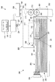
図1は、本発明の例示的な実施形態におけるイメージ形成装置100の模式図である。このイメージ形成装置100は、記録媒体のシートにイメージを固定するイメージ形成エンジン110を有している。ユーザインターフェース120により、イメージ形成装置100のユーザは、シートの合計の印刷枚数を含めて印刷リクエストを入力する。ユーザは、印刷されるシートの特性も入力できる。この特性には、シートの基本重量、シートのサイズ、及びシート上のコーティングが含まれ得る。シートフィーダ200が、シートをスタックの頂部から分離し、この分離されたシートを獲得して、イメージ形成エンジン110に分離されたシートを渡す。制御回路300は、それまでにうまくフィードされた所定の枚数のシートに対する連続平均及び標準偏差に基づいて、シート獲得時間を制御する。制御回路300はまた、スタックの位置を調整するとともに、獲得されたシートを受け取ってイメージ形成エンジン110にそのシートを渡すテークアウエイニップロールを制御する。
【0008】
図2は、本発明に従ったシートフィーダ200及び制御回路300のある例示的な実施形態の側方模式図である。シートフィーダ200はサポートトレイ201を含み、このサポートトレイ201は傾動可能で、様々な特性を有するシートを収容するように自己調整する。シートのスタック202は、シートサポートトレイ201の上に支持されていて、スタック202の前端203が合わせ(レジストレーション;registration)壁204に当接する。シートフラッファー205及び206は、スタック202に空気をブローして、スタック202からトップシート207を分離する。後端シートフラッファー205は、スタック202の後端208に空気をブローする。側端シートフラッファー206は、実際には2つあるうちの1つしか図2では示されていないが、これら2つの側端シートフラッファー206は、スタック202の両側部にそれぞれ空気をブローする。
【0009】
フィードヘッドアセンブリ209はハウジング210を含み、このハウジング210が、テークアウエイニップロール212に向かう動き及びそこから離れる動きを行う直動真空フィードヘッド211を支持している。テークアウエイニップロール212は、ステッピングモータ213によって駆動される。直動真空フィードヘッド211内のシート獲得センサ216が、直動真空フィードヘッド211の獲得表面215によってトップシート207が獲得されたことを検出する。真空圧力が、ブロワーアセンブリ217によって真空マニホールド218を通じて直動真空フィードヘッド211に印加される。例示的な実施形態では、ブロワーアセンブリ217は、可変速ブラシレスDCモータを含んでいる。
【0010】
空気が、ブロワーアセンブリ217から正圧力プレナム250に供給される。空気は、正圧力プレナム250から、それぞれフラッファーマニホールド219及び220を通じてシートフラッファー205及び206に供給される。空気はまた、正圧力プレナム250から空気ナイフ251にも供給される。空気は、正圧力プレナム250から、空気ナイフマニホールド252を通じて空気ナイフプレナム253に供給される。空気ナイフ251は、獲得表面215によって獲得されたトップシートから、副次的に獲得されたシートを分離する。副次的に獲得されたシートとは、獲得表面215によって獲得されたトップシート207に付着しているシートである。
【0011】
真空マニホールド218は、真空マニホールドバルブ221によって開閉される。真空マニホールドバルブ221を開けると、真空圧力がブロワーアセンブリ217によって直動真空フィードヘッド211に印加される。ある例示的な実施形態では、真空マニホールドバルブ221は、ステッピングモータによって開けられる。真空マニホールドバルブセンサ224は、真空マニホールドバルブ221が開いたことを検出する。真空マニホールドバルブ221が開けられたことを真空マニホールドバルブセンサ224が検出すると、制御回路300に信号が送られる。
【0012】
フィードヘッドアセンブリ209のハウジング210は、直動真空フィードヘッド211のための単方向性回転ドライブ機構225、スタック高さセンサ226、及び始端高度センサ227も支持している。スタック高さセンサ226も単方向性回転ドライブ機構225によって駆動されて、直動真空フィードヘッド211によってテークアウエイニップロール212にフィードされたトップシート207の終端がスタック高さセンサ226を通過した後に、スタック202の頂部に接触する。スタック高さセンサ226及び始端高度センサ227は、サポートトレイ201の位置を制御するために使用される。
【0013】
制御回路300は、メモリ320を有するコントローラ310を含む。ある例示的な実施形態では、コントローラ310は、フィードヘッドアセンブリ209内の真空マニホールドバルブセンサ224及びシート獲得センサ216から信号を受領し、この信号に応答してブロワーアセンブリ217を制御する。別の例示的な実施形態では、コントローラ310は、真空マニホールドバルブセンサ224及び始端高度センサ227から信号を受領し、この信号に応答してブロワーアセンブリ217を制御する。コントローラ310はまた、スタック高さセンサ226及び始端高度センサ227から信号を受領し、この信号に応答してサポートトレイ201の位置を制御する。コントローラ310はまた、テークアウエイニップロール212を駆動するステッピングモータ213を、メモリ320に記憶された制御プログラムを実行することによって制御する。
【0014】
図3は、直動真空フィードヘッド211の模式的な側方断面図である。直動真空フィードヘッド211は、プレナム214及び獲得表面215を含む。ある例示的な実施形態では、プレナム214は、射出成形されたプラスチックで形成されている。プレナム214は、一つの側面に形成されたポート228を含み、これが真空マニホールド218に接続されている。ポート228と真空マニホールド218との接合部はスライディングシール(図示せず)を含み、これにより、直動真空フィードヘッド211が、真空マニホールド218への接続を維持しながら、テークアウエイニップロール212に向かって及びそれから離れるように移動することが可能になる。シートの獲得時にポート228と真空マニホールド218との接合部で測定された圧力は、シール済みポート圧力と規定される。
【0015】
シート獲得センサ216は、ポート228の近くでプレナム214に搭載されており、始端高度センサ227は、プレナム214の前方端に搭載されている。シート獲得は、シート獲得センサ216又は始端高度センサ227の何れかによって検出されることができる。
【0016】
図4に示されているように、獲得表面215は、コルゲートプレート256を含む。このコルゲートプレート256は、複数のコルゲートリブ255、複数の開口部229、及び複数のカットアウト230を含み、直動真空フィードヘッド211が前進位置にあると、コルゲートプレート256がテークアウエイニップロール212を囲む。獲得表面215はエラストマであり、獲得されたシートにはシート分離を改善するようにしわが寄り、それから、真空フィードヘッド211が単方向性回転ドライブ機構225によって前方に駆動されるにつれて、摩擦によってコルゲートプレート256により動かされる。獲得されたシートの始端がテークアウエイニップロール212に到達すると、真空マニホールドバルブ221が閉じて、獲得表面215との接触によってシート上で引きずられること(drag)を防ぐ。獲得表面215が摩耗してきたら、コルゲートプレート256を交換してもよい。コルゲートプレート256を、フィードされるべきシートの特性に応じて、異なった数の開口部及び/又は異なるサイズの開口部を有する異なるコルゲートプレートに交換してもよい。
【0017】
シート獲得センサ216は、直動真空フィードヘッド211によるトップシート207の獲得を検出する。ある例示的な実施形態では、シート獲得センサ216は、獲得表面215のたわみを検出する。トップシート207が直動真空フィードヘッド211によって獲得されると、このトップシート207が、コルゲートプレート256の開口部229を覆う。真空圧力がブロワーアセンブリ217によってプレナム214に印加されると、この真空圧力によって、コルゲートプレート256がプレナム214に入るように上方に湾曲する。シート獲得センサ216は、コルゲートプレート256のこの湾曲を検出する。湾曲量は、シートの特性に依存する。変化する特性を有するシートが直動真空フィードヘッド211によって獲得されるときに生じる湾曲量が実験的に決定され、この結果が、コントローラ310のメモリ320に記憶される。シート獲得センサ216は、コルゲートプレート256の湾曲を示す信号をコントローラ310に送る。湾曲が、フィードされているシートの特定の特性に対してメモリ320に記憶されている湾曲量に等しいか、又はその特定のパーセンテージであると、コントローラ310は、トップシート207が直動真空フィードヘッド211によって獲得されたと判定する。
【0018】
別の例示的な実施形態では、シート獲得センサ216は、直動真空フィードヘッド211がトップシート207を獲得するときに生じるシール済みポート圧力を検出する。トップシート207が獲得されると、コルゲートプレート256の開口部229が覆われる。真空圧力がブロワーアセンブリ217によってプレナム214に印加されると、シール済みポート圧力が増加する。変化する特性を有するシートが直動真空フィードヘッド211によって獲得されるときに生じるシール済みポート圧力が実験的に決定され、この結果が、コントローラ310のメモリ320に記憶される。シート獲得センサ216は、シール済みポート圧力を示す信号をコントローラ310に送る。シール済みポート圧力が、フィードされているシートの特定の特性に対してメモリ320に記憶されている湾曲量に等しいか、又はその特定のパーセンテージであると、コントローラ310は、トップシート207が直動真空フィードヘッド211によって獲得されたと判定する。
【0019】
別の例示的な実施形態では、始端高度センサ227がシート獲得を検出する。始端高度センサ227は、位置検出デバイス(position sensitive device)、又は異なる焦点距離を有する複数のセンサを含んでいてもよい。ある例示的な実施形態では、始端高度センサ227は4つの検出器を有する赤外線LEDであり、これらの検出器が、トップシート207の始端の位置を、獲得表面215からそれぞれ0mm〜3mm、3mm〜6mm、6mm〜9mm、又は9mmを超えるレンジにあると判定する。始端高度センサ227は、信号をコントローラ310に送る。この信号が、トップシート207の始端が0〜3mmレンジにあることを示すと、コントローラ310は、トップシート207が獲得されたと判定する。
【0020】
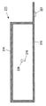
シートをシートフィーダ200からイメージ形成エンジン110にフィードするには、スタック202がサポートトレイ201に位置される。図5に示されているように、サポートトレイ201は、エレベータ231及び232によって両端が支持されている。各エレベータ231及び232は、独立したモータ233及び234によってそれぞれ駆動される。本発明の様々な例示的な実施形態では、これらのモータ233及び234は、ステッピングモータ又はブラシレスDCモータであることができる。サポートトレイ201は、独立したモータ233及び234の一方又は両方を駆動することによって、上昇又は下降され、及び/又は傾斜される。スタック202がロードされると、コントローラ310は独立したモータ233及び234を駆動し、サポートトレイ201を初期スタック高さに上昇させる。スタック高さは、スタック202の頂部から獲得表面215までの距離として規定される。
【0021】
初期スタック高さは、ユーザインターフェースに入力される、シートサイズ及びシート基本重量を含むシート特性に依存する。重量級シートは、軽量級シートよりも獲得が困難であり、ミスフィード又は獲得遅れを生じやすい。従って、重量級シートのスタックは、初期状態で、獲得表面215により近いレンジに位置される。軽量級シートは獲得されやすく、マルチフィードを生じやすい。従って、軽量級シートのスタックは、獲得表面215からより遠くに離れたレンジに位置される。変化するシート基本重量を有する特定のシートに対する初期スタック高さが実験的に決定され、メモリ320に記憶される。信号が、スタック高さセンサ226及び始端高度センサ227からコントローラ310に送られる。コントローラ310は、独立したモータ233及び234を駆動して、初期スタック高さを設定する。
【0022】
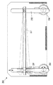
図6〜図9に示されているように、スタック高さセンサはスタック高さセンサアーム235を含み、このアーム235は、スタック高さセンサアーム235の頂部に位置するジャーナル237を通過するシャフト236によって、フィードヘッドアセンブリ209のハウジング210にピボット回転可能に搭載されている。スタック高さセンサアーム235は、ばね(図示せず)によって付勢され、スタック202の頂部に接触する。図6〜図9では、スタック高さセンサ226をより明瞭にみることができるように、フィードヘッドアセンブリ209のハウジング210は示されていない。スタック高さセンサアーム235の端部のローラ238は、スタック202の頂部に接触し及びそこから離れるように移動可能である。図7に示されているように、フラグ239及び240の対が、スタック高さセンサアーム235のジャーナル237から延びている。各フラグ239及び240の位置は、透過性センサ241及び242によってそれぞれ検出される。透過性センサ241及び242によってそれぞれ検知されたフラグ239及び240の位置は、スタック高さを決定する。図6に示されているように、スタック高さセンサ226は、15mmを超える、15mm〜12.5mm、12.5mm〜10mm、及び10mmより小さい、という4つのレンジのうちの1つに、スタック高さを決定する。
【0023】
スタック高さセンサ226及び始端高度センサ227は、コントローラ310が独立したモータ233及び234を駆動してサポートトレイ201を上昇させるときに、スタック高さを示す信号をコントローラ310に送る。スタック高さセンサ226及び始端高度センサ227が、スタック高さが、フィードされる特定のシートに対してメモリ320に記憶されている初期スタック高さに等しいことを示すときには、コントローラ310は、独立モータ233及び234の駆動を停止する。
【0024】
スタック202が初期スタック高さに設定され、印刷リクエストがユーザインターフェース120に入力されると、ブロワーアセンブリ217がオンされる。終端シートフラッファー205、側端シートフラッファー206、及び空気ナイフ251にブロワーアセンブリ217から空気が供給され、トップシート207をスタック202の頂部から分離する。直動真空フィードヘッド211には、ブロワーアセンブリ217によって真空圧力が供給される。トップシート207が、直動真空フィードヘッド211によって獲得される。
【0025】
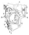
図8及び図9に示されているように、ある例示的な実施形態では、直動真空フィードヘッド211は、各コーナ部で、ハウジング(図示せず)のスライド244のボールベアリング又は低摩擦ローラ243によって支持されている。直動真空フィードヘッド211は、単方向性回転ドライブ機構225によって、前進し且つホーム位置へ復帰するように駆動される。センサ254は、直動真空フィードヘッド211がホーム位置にあるときに、直動真空フィードヘッド211を検出する。単方向性回転ドライブ機構225は2つのスライダ・クランク245を含んでいるが、そのうちの1つのみが図8及び図9に示されている。スライダ・クランク245は、単方向性ダブルシャフトステッピングモータ246のシャフトに搭載されている。例示的な実施形態では、直動真空フィードヘッド211は、20mm前進し且つホーム位置まで20mm後退するように駆動される。これは、ペーパローディング公差及びミスレジストレーションを考慮して、5mmのオーバートラベル分を含んでいる。
【0026】
単方向性回転ドライブ機構225は、獲得されたシートをテークアウエイニップロール212に例えば約430mm/秒の速度で運ぶ速度プロファイルで、直動真空フィードヘッド211を前進させる。トップシート207が、テークアウエイニップロール212に渡される。テークアウエイニップロール212は、コントローラ310によって制御されるステッピングモータ213によって駆動される。トップシート207がテークアウエイニップロール212に渡されると、コントローラ310はステッピングモータ213の速度を上げて、イメージ形成エンジン110の運搬速度にマッチするようにトップシート207を加速する。
【0027】
図8及び図9に示されているように、スタック高さセンサアーム235はカムフォロワ247を含む。カム248は、ダブルシャフトステッピングモータ246のシャフトに搭載されている。カム248は、スタック高さセンサアーム235上のカムフォロワ247に係合する部分を含んでおり、これが、スタック高さセンサアーム235の端部のローラ238を、スタック202の頂部に接触しなくなるように持ち上げる。カム248に含まれる別の部分によって、ばねで付勢されたスタック高さセンサアーム235が、ローラ238を、スタック202の頂部に接触するように下げる。
【0028】
直動真空フィードヘッド211がトップシート207をテークアウエイニップロール212に渡した後に、直動真空フィードヘッド211は前進位置で休止して、トップシート207の終端にローラ238を通過させる。ローラ238は、カム248によって、スタック202の頂部から離れるように持ち上げられる。トップシート207の終端がスタック高さセンサ226のローラ238を通過する直前に、休止状態が終了し、単方向性ドライブ225が直動真空フィードヘッド211をホーム位置に戻しはじめる。直動真空フィードヘッド211がホーム位置に到達する前に、カム248は、ローラ238をスタック202に接触させるような位置まで回転させる。
【0029】
ある例示的な実施形態では、ローラ238は、25msの間、スタック202と接触している。透過性センサ241及び242は、スタック高さを示す信号をコントローラ310に送る。始端高度センサ227からの信号も、コントローラ310に送られる。シートがスタック202からフィードされると、コントローラ310は、独立モータ233及び234を駆動することによって、これらの信号に応答してサポートトレイ201の位置を調整し、始端高度センサ227によって示された所望のスタック高さ及びスタック位置を維持する。単方向性回転ドライブ機構225が直動真空フィードヘッド211をホーム位置に戻すと、カム248は、ローラ238を持ち上げてスタック202から離す。
【0030】
シート獲得時間は、真空マニホールドバルブセンサ224によって感知される真空マニホールドバルブ221の開放時から、シート獲得センサ216又は始端高度センサ227によって感知される、直動真空フィードヘッド211の獲得表面215によるトップシート207の獲得までの時間として、規定される。シートフィーダ200の性能は、終端シートフラッファー205、側端シートフラッファー206、及び空気ナイフ251の圧力、並びに直動真空フィードヘッド211の真空圧力の調整によって、フィード動作中にシート獲得時間を動的に調整することによって、改良され得る。
【0031】
シートフィーダ200は、ブロワーアセンブリ217からシートフラッファー205及び206と直動真空フィードヘッド211とにそれぞれ供給される正及び負の空気圧力を使用して、スタック202の頂部から個々のシートを獲得し、それらをテークアウエイニップロール212まで前進させる。シート獲得時間に影響を与えるシートフィーダ200の独立変数の中には、シートフラッファー圧力及び真空圧力がある。フラッファー圧力が増加すると、スタック202の頂部のシートの分離が促進され、最上部のシートが直動真空フィードヘッド211に更に近くなるように持ち上げられて、これによってシート獲得時間が減少する。フラッファー圧力が増加すると、マルチフィードのリスクも増加する。フラッファー圧力が減少すると、スタック202の頂部のシートがスタック202の頂部から分離し難くなり、これによってシート獲得時間が増加する。フラッファー圧力が減少すると、ミスフィード及び/又は獲得遅れのリスクが増加する。
【0032】
シート獲得時間は、シートサイズ及びシート基本重量の関数である。特定のサイズ及びシート基本重量のシートに対する所定のシート獲得時間は、実験的に決定されてメモリ320に記憶されている。ブロワーアセンブリ217は、シートフィード動作中に動的に調整されることができて、オペレータによってユーザインターフェース120に入力されるシート特性情報、及び真空マニホールドセンサ224及びシート獲得センサ216又は始端高度センサ227からの情報を使用して、シート獲得時間を動的に制御できる。
【0033】
図10は、本発明に従ったシート獲得時間制御方法のある例示的な実施形態の概略を描くフローチャートである。ステップS100で開始されると、コントロールはステップS200に続いて、ユーザが印刷リクエストコマンドをユーザインターフェースに入力する。印刷リクエストコマンドは、シートの合計印刷枚数Tを含む。次に、ステップS300で、カウンタが初期値N=0に設定される。次にステップS400で、初期スタック高さ、シートフラッファー及び空気ナイフの初期圧力、並びに直動真空フィードヘッドに供給される初期真空圧力が決定される。初期スタック高さ及び圧力は、オペレータによって入力されるか又はイメージ形成装置100内のセンサによって自動的に感知されるシート特性に従って、設定される。初期スタック高さは、ペーパスタックの頂部とシート獲得表面との間の距離を調整することによって、設定される。初期圧力は、特定のシート特性に対して実験的に決定される初期圧力テーブルを参照することによってシート特性に従って設定されるか、又は、シート特性に従って実験的に決定される等式によって設定される。初期圧力のテーブル又は等式は、メモリに記憶されている。コントロールは、次にステップS500に続く。
【0034】
ステップS500で、第1のシートがフィードされる。次に、ステップS600で、カウンタ値Nが1だけインクリメントされる。次にステップS700で、インクリメントされた値が、リクエストされているシートの総数Tと比較される。インクリメントされた値がリクエストされているシートの総数Tと等しければ、コントロールはステップS1200にジャンプする。そうでない場合には、インクリメントされた値がリクエストされているシートの総数Tよりも小さければ、コントロールはステップS800に続く。
【0035】
ステップS800で、シート獲得時間が決定される。先に述べたように、シート獲得時間は、シート獲得表面への真空圧力の印加から、トップシートの獲得までの時間として決定される。
【0036】
次にステップS900にて、これまでにうまくフィードされた所定枚数のシートに対する平均シート獲得時間及び標準偏差が決定される。例示的な実施形態では、この所定の枚数は50である。実際にフィードされたシート枚数がこの所定の枚数を超えるまでは、うまくフィードされた全てのシートに対する平均シート獲得時間及び標準偏差が決定される。
【0037】
次にステップS1000にて、平均シート獲得時間及び標準偏差が、所定のシート獲得時間及び標準偏差と比較される。これまでにうまくフィードされた所定枚数のシートに対する平均シート獲得時間及び標準偏差が所定の範囲内であるときには、コントロールはステップS500にジャンプして戻る。そうでない場合には、これまでにうまくフィードされた所定枚数のシートに対する平均シート獲得時間及び標準偏差が所定の範囲よりも上又は下であると、コントロールはS1100に続く。ステップS1100では、ブロワーアセンブリ217が調整される。
【0038】
シート獲得時間が所定の値よりも長いと、シートフラッファー圧力及びシート獲得表面に印加される真空圧力が増加されて、シート獲得時間を短くする。シート獲得時間が所定の値よりも短いと、シートフラッファー圧力及びシート獲得表面に印加される真空圧力が減少されて、シート獲得時間を長くする。
【0039】
ステップS1200で、実際にフィードされたシート数が、印刷リクエストコマンドに特定された所定の数Tに等しくなると、コントロールが終了する。
【0040】
図1及び図2に示されている制御回路300を、適切にプログラミングされた汎用コンピュータの一部として実現されることができることに、留意されたい。あるいは、制御回路は、ASIC内部の物理的に異なったハードウエアとして、或いは、FPGA、PDL、PLA、又はPALを使用して、あるいはディスクリート論理素子又はディスクリート回路素子を使用して、実現されることもできる。図1及び図2に示されている制御回路が有している特定の形態は、一つの設計上の選択であり、当業者には明らかで且つ予測可能である。
【0041】
図10に示されているように、シート獲得時間制御方法は、プログラムされた汎用コンピュータ上に実現されることができる。しかし、シート獲得時間制御シーケンスは、特定用途向けコンピュータ、プログラム化マイクロプロセッサ又はマイクロコントローラ及び周辺集積回路素子、ASIC又はその他の集積回路、デジタルシグナルプロセッサ、ディスクリート素子回路のようなハードワイヤ接続された(ハードワイヤド;hardwired)電子回路又はログ回路、PLD、PLA、FPGA、又はPALのようなプログラマブル論理デバイスなどの上に、実現されることもできる。一般的に、有限状態マシンを実現することができて、これにより図10の流れ図を実現することができる任意のデバイスを使用して、シート獲得時間制御方法を実現することができる。
【0042】
図2に示されているように、メモリ320は、ROMを使用して実現されてもよい。しかし、メモリ320は、PROM、EPROM、CD−ROM又はDVD−ROMのような光ROMディスク、及びディスクドライブなどを使用して、実現されることもできる。
【0043】
本発明を、上記で概説した例示的な実施形態に関連して説明してきたが、多くの改変、変更、及び変化が当業者には明らかであることが、明白である。従って、上記で述べた本発明の例示的な実施形態は、描写的であることを意図したものであり、限定的であることを意図したものではない。本発明の思想及び範囲を逸脱することなく、様々な変更を行ってもよい。
【図面の簡単な説明】
【図1】 本発明に従ったイメージ形成装置の模式図である。
【図2】 本発明に従ったシートフィーダを模式的に描く側面図である。
【図3】 フィードヘッドの側方断面図である。
【図4】 フィードヘッドのコルゲートプレートの平面図である。
【図5】 シートフィーダのサポートトレイ及びエレベータの模式的な側面図である。
【図6】 本発明に従ったスタック高さセンサのレンジを描く模式的な側面図である。
【図7】 本発明に従ったスタック高さセンサの斜視図である。
【図8】 本発明に従ったフィードヘッド及びスタック高さセンサに対する単方向性回転ドライブ機構の斜視図である。
【図9】 本発明に従ったフィードヘッド及びスタック高さセンサに対する単方向性回転ドライブ機構の斜視図である。
【図10】 本発明に従ったシート獲得時間調整制御方法のフローチャートである。
【符号の説明】
200 シートフィーダ、201 サポートトレイ、202 シートのスタック、203 スタックの前端、205 後端シートフラッファー、206 側端シートフラッファー、207 トップシート、208 スタックの後端、209フィードヘッドアセンブリ、210 ハウジング、211 直動真空フィードヘッド、212 テークアウエイニップロール、213 ステッピングモータ、215 獲得表面、216 シート獲得センサ、217 ブロワーアセンブリ、218 真空マニホールド。219 220 フラッファーマニホールド。221 真空マニホールドバルブ、224 真空マニホールドバルブセンサ、225単方向性回転ドライブ機構、226 スタック高さセンサ、227 始端高度センサ、250 正圧力プレナム、251 空気ナイフ、252 空気ナイフマニホールド、253 空気ナイフプレナム、300 制御回路、310 コントローラ、320 メモリ。[0001]
BACKGROUND OF THE INVENTION
The present invention generally relates to a sheet feeder for an image forming engine of an image forming apparatus.
[0002]
[Prior art]
To supply the image forming engine with an image recording medium, commonly referred to as a “sheet”, an individual copy sheet is obtained from the top of the stack and is fed by a linear motion vacuum feedhead to the takeaway nip roll. Advance into the set. A sheet fluffer separates one sheet from the top of the stack, and a direct acting vacuum feedhead acquires the separated sheet and advances the separated sheet into a set of takeaway nip rolls. .
[0003]
[Problems to be solved by the invention]
The time for the direct acting vacuum feedhead to obtain separated sheets is relatively short. As fluffing or vacuum pressure increases, sheet acquisition time decreases. Accordingly, the risk that two or more sheets are moved into the set of takeaway nip rolls (ie, the risk of multi-feed error) is also increased. If the fluffing pressure is reduced, the top sheet may not be close enough to the direct acting vacuum feed head so that when the direct acting vacuum feed head is advanced into the set of takeaway nip rolls, one sheet May not be fed (i.e., misfeed error) or the acquisition of the sheet may be delayed. Fluffer and vacuum pressure is g / m 2 Determined by paper properties such as sheet basis weight, size, and coating measured in (gsm). These paper characteristics can be entered by the user or automatically determined by sensors in the image forming device.
[0004]
[Means for Solving the Problems]
The sheet feeder of the present invention includes a sheet separator that separates sheets from a stack of sheets, a feedhead that receives sheets separated from the stack, and a controller that adjusts a sheet acquisition time for the feedhead to acquire the sheets; Is provided.
[0005]
According to an exemplary embodiment of a system according to the present invention, a sheet feeding device for an image forming apparatus includes a selectively drivable vacuum source and a top sheet of a stack attached to the vacuum source. It includes a direct acting vacuum feedhead to acquire, a unidirectional rotary drive mechanism, and a control circuit. The unidirectional rotary drive mechanism is driven in a single direction to reciprocate the linear motion vacuum feed head between a first position and a second position. The control circuit dynamically adjusts the positive and vacuum pressures to prevent multifeeds, misfeeds, and / or acquisition delays. The sheet acquisition time is the time from when the vacuum manifold valve is opened until the sheet is acquired by the direct acting vacuum feed head. In an exemplary embodiment, the control circuit controls the sheet acquisition time based on a running average and standard deviation for a predetermined number of sheets that have been successfully fed so far.
[0006]
Other features of the present invention will become apparent as the following description proceeds and by reference to the drawings.
[0007]
DETAILED DESCRIPTION OF THE INVENTION
FIG. 1 is a schematic diagram of an
[0008]
FIG. 2 is a side schematic view of an exemplary embodiment of a
[0009]
The
[0010]
Air is supplied from the
[0011]
The
[0012]
The
[0013]
The
[0014]
FIG. 3 is a schematic side sectional view of the direct acting
[0015]
The
[0016]
As shown in FIG. 4, the
[0017]
The
[0018]
In another exemplary embodiment, the
[0019]
In another exemplary embodiment, the
[0020]
To feed sheets from the
[0021]
The initial stack height depends on the sheet characteristics, including sheet size and sheet basis weight, entered into the user interface. A heavyweight sheet is more difficult to acquire than a lightweight sheet and is prone to misfeeds or acquisition delays. Thus, the stack of heavyweight sheets is positioned in a range closer to the
[0022]
As shown in FIGS. 6-9, the stack height sensor includes a stack
[0023]
The
[0024]
When
[0025]
As shown in FIGS. 8 and 9, in one exemplary embodiment, the
[0026]
The unidirectional
[0027]
As shown in FIGS. 8 and 9, the stack
[0028]
After the linear motion
[0029]
In an exemplary embodiment,
[0030]
The sheet acquisition time is the top sheet by the
[0031]
The
[0032]
Sheet acquisition time is a function of sheet size and sheet basis weight. The predetermined sheet acquisition time for a sheet of a particular size and sheet basis weight is determined experimentally and stored in the
[0033]
FIG. 10 is a flowchart outlining an exemplary embodiment of a sheet acquisition time control method according to the present invention. Beginning in step S100, control continues to step S200 where the user enters a print request command into the user interface. The print request command includes the total number T of printed sheets. Next, in step S300, the counter is set to an initial value N = 0. Next, in step S400, the initial stack height, the initial pressure of the sheet fluffer and the air knife, and the initial vacuum pressure supplied to the direct acting vacuum feed head are determined. The initial stack height and pressure are set according to sheet characteristics that are input by an operator or automatically sensed by sensors in the
[0034]
In step S500, the first sheet is fed. Next, in step S600, the counter value N is incremented by one. Next, in step S700, the incremented value is compared to the total number T of requested sheets. If the incremented value is equal to the total number T of requested sheets, control jumps to step S1200. Otherwise, if the incremented value is less than the total number T of requested sheets, control continues to step S800.
[0035]
In step S800, the sheet acquisition time is determined. As mentioned above, the sheet acquisition time is determined as the time from application of vacuum pressure to the sheet acquisition surface to the acquisition of the top sheet.
[0036]
Next, in step S900, the average sheet acquisition time and standard deviation for a predetermined number of sheets that have been successfully fed so far are determined. In the exemplary embodiment, this predetermined number is fifty. Until the number of sheets actually fed exceeds the predetermined number, the average sheet acquisition time and standard deviation for all the successfully fed sheets are determined.
[0037]
Next, in step S1000, the average sheet acquisition time and standard deviation are compared with a predetermined sheet acquisition time and standard deviation. When the average sheet acquisition time and standard deviation for a predetermined number of sheets successfully fed so far are within a predetermined range, control jumps back to step S500. Otherwise, if the average sheet acquisition time and standard deviation for a predetermined number of sheets successfully fed so far are above or below a predetermined range, control continues to S1100. In step S1100, the
[0038]
If the sheet acquisition time is longer than a predetermined value, the sheet fluffer pressure and the vacuum pressure applied to the sheet acquisition surface are increased to shorten the sheet acquisition time. When the sheet acquisition time is shorter than a predetermined value, the sheet fluffer pressure and the vacuum pressure applied to the sheet acquisition surface are reduced, thereby increasing the sheet acquisition time.
[0039]
In step S1200, when the number of sheets actually fed becomes equal to the predetermined number T specified in the print request command, the control is finished.
[0040]
It should be noted that the
[0041]
As shown in FIG. 10, the sheet acquisition time control method can be realized on a programmed general-purpose computer. However, the sheet acquisition time control sequence is hardwired such as an application specific computer, programmed microprocessor or microcontroller and peripheral integrated circuit element, ASIC or other integrated circuit, digital signal processor, discrete element circuit ( It can also be realized on a hardwired electronic circuit or log circuit, a programmable logic device such as PLD, PLA, FPGA, or PAL. In general, any device that can implement a finite state machine and thereby implement the flowchart of FIG. 10 can be used to implement the sheet acquisition time control method.
[0042]
As shown in FIG. 2, the
[0043]
While the invention has been described in connection with the exemplary embodiments outlined above, it will be apparent to those skilled in the art that many modifications, changes and variations will be apparent to those skilled in the art. Accordingly, the exemplary embodiments of the invention described above are intended to be illustrative and not limiting. Various changes may be made without departing from the spirit and scope of the invention.
[Brief description of the drawings]
FIG. 1 is a schematic diagram of an image forming apparatus according to the present invention.
FIG. 2 is a side view schematically illustrating a sheet feeder according to the present invention.
FIG. 3 is a side sectional view of a feed head.
FIG. 4 is a plan view of a corrugated plate of a feed head.
FIG. 5 is a schematic side view of a support tray and an elevator of a sheet feeder.
FIG. 6 is a schematic side view depicting the range of a stack height sensor according to the present invention.
FIG. 7 is a perspective view of a stack height sensor according to the present invention.
FIG. 8 is a perspective view of a unidirectional rotary drive mechanism for a feedhead and stack height sensor according to the present invention.
FIG. 9 is a perspective view of a unidirectional rotary drive mechanism for a feedhead and stack height sensor according to the present invention.
FIG. 10 is a flowchart of a sheet acquisition time adjustment control method according to the present invention.
[Explanation of symbols]
200 sheet feeder, 201 support tray, 202 sheet stack, 203 stack front end, 205 rear end sheet fluffer, 206 side end sheet fluffer, 207 top sheet, 208 stack rear end, 209 feed head assembly, 210 housing, 211 direct acting vacuum feed head, 212 takeaway nip roll, 213 stepping motor, 215 acquisition surface, 216 sheet acquisition sensor, 217 blower assembly, 218 vacuum manifold. 219 220 Fluffer manifold. 221 vacuum manifold valve, 224 vacuum manifold valve sensor, 225 unidirectional rotary drive mechanism, 226 stack height sensor, 227 start height sensor, 250 positive pressure plenum, 251 air knife, 252 air knife manifold, 253 air knife plenum, 300 Control circuit, 310 controller, 320 memory.
Claims (1)
前記スタックから分離されたシートを受け取るフィードヘッドと、
前記フィードヘッドが前記シートを獲得するシート獲得時間を調整するコントローラと、を備え、
前記コントローラは、うまくフィードされた所定枚数のシートに対する平均シート獲得時間及び標準偏差を決定し、決定した平均シート獲得時間及び標準偏差が所定の範囲内であれば現在の状態をそのまま維持し、所定の範囲よりも上又は下であるとシート獲得時間を調整するものであって、平均シート獲得時間が所定の範囲の上限である所定の値よりも大きければシート獲得時間を短くするように制御し、平均シート獲得時間が所定の範囲の下限である所定の値よりも小さければシート獲得時間を長くするように制御するシートフィーダ。A sheet separator for separating sheets from a stack of sheets;
A feedhead for receiving sheets separated from the stack;
A controller for adjusting a sheet acquisition time for the feedhead to acquire the sheet, and
Wherein the controller determines the average sheet acquisition time and standard deviation for sheet was successfully feed a predetermined number, the determined average sheet acquisition time and standard deviation are maintained the current state is within a predetermined range, a predetermined If the average sheet acquisition time is larger than a predetermined value which is the upper limit of the predetermined range, the sheet acquisition time is controlled to be shortened. A sheet feeder that controls to increase the sheet acquisition time if the average sheet acquisition time is smaller than a predetermined value that is the lower limit of the predetermined range .
Applications Claiming Priority (2)
| Application Number | Priority Date | Filing Date | Title |
|---|---|---|---|
| US09/416417 | 1999-10-12 | ||
| US09/416,417 US6279896B1 (en) | 1999-10-12 | 1999-10-12 | Systems and methods for dynamically setting air system pressures based on real time sheet acquisition time data |
Publications (2)
| Publication Number | Publication Date |
|---|---|
| JP2001151361A JP2001151361A (en) | 2001-06-05 |
| JP4716552B2 true JP4716552B2 (en) | 2011-07-06 |
Family
ID=23649894
Family Applications (1)
| Application Number | Title | Priority Date | Filing Date |
|---|---|---|---|
| JP2000309423A Expired - Fee Related JP4716552B2 (en) | 1999-10-12 | 2000-10-10 | Sheet feeder |
Country Status (5)
| Country | Link |
|---|---|
| US (1) | US6279896B1 (en) |
| EP (1) | EP1092659B1 (en) |
| JP (1) | JP4716552B2 (en) |
| BR (1) | BR0004784B1 (en) |
| DE (1) | DE60027104T2 (en) |
Families Citing this family (31)
| Publication number | Priority date | Publication date | Assignee | Title |
|---|---|---|---|---|
| JP2000185829A (en) * | 1998-12-23 | 2000-07-04 | Xerox Corp | Paper feeder |
| DE10151423B4 (en) * | 2000-10-26 | 2014-07-24 | Heidelberger Druckmaschinen Ag | Device for adjusting an air flow influencing a sheet transport in a printing machine, and corresponding method |
| US6460846B2 (en) * | 2000-12-18 | 2002-10-08 | Xerox Corporation | Reproduction machine having a safe tiltable paper tray |
| EP1490777B1 (en) * | 2002-03-15 | 2011-05-18 | Kirtas Technologies, Inc. | Page turning apparatus with a vacuum plenum and an adaptive air fluffer |
| JP4616647B2 (en) * | 2002-09-10 | 2011-01-19 | キルタス テクノロジーズ、インコーポレイテッド | Automatic page turning device that supports browsing of document pages |
| US7096407B2 (en) * | 2003-02-18 | 2006-08-22 | Hewlett-Packard Development Company, L.P. | Technique for implementing chipkill in a memory system |
| US7458570B2 (en) * | 2004-09-13 | 2008-12-02 | Ricoh Printing Systems, Ltd. | Sheet-supplying device |
| US7413182B2 (en) * | 2005-03-04 | 2008-08-19 | Hewlett-Packard Development Company, L.P. | Printing system and method |
| US7431286B2 (en) * | 2005-03-04 | 2008-10-07 | Hewlett-Packard Development Company, L.P. | Media stack measurement and method |
| US7258336B2 (en) * | 2005-09-20 | 2007-08-21 | Xerox Corporation | Integrated vacuum slide feeder |
| US7472902B2 (en) * | 2005-09-20 | 2009-01-06 | Xerox Corporation | System and method for improving top sheet acquisition in a printing machine |
| JP4717685B2 (en) * | 2006-04-03 | 2011-07-06 | キヤノン株式会社 | Sheet feeding apparatus and image forming apparatus |
| US7591459B2 (en) * | 2006-04-03 | 2009-09-22 | Canon Kabushiki Kaisha | Sheet feeding apparatus and image forming apparatus |
| JP2007308295A (en) * | 2006-05-22 | 2007-11-29 | Canon Inc | Sheet feeding apparatus and image forming apparatus |
| WO2008157764A1 (en) * | 2007-06-21 | 2008-12-24 | Kirtas Technologies, Inc. | Automated page turning apparatus to assist in viewing pages of a document |
| JP4979515B2 (en) * | 2007-08-28 | 2012-07-18 | キヤノン株式会社 | Sheet feeding apparatus and image forming apparatus |
| JP4950812B2 (en) * | 2007-08-29 | 2012-06-13 | 株式会社東芝 | Paper sheet take-out device |
| US20090180085A1 (en) * | 2008-01-15 | 2009-07-16 | Kirtas Technologies, Inc. | System and method for large format imaging |
| US7819397B2 (en) * | 2008-06-25 | 2010-10-26 | Xerox Corporation | Media stack sheet fluffer method and apparatus, and a media processing device arranged with the same |
| US8485517B2 (en) * | 2008-08-07 | 2013-07-16 | Xerox Corporation | Method and apparatus for feeding sheets of media from a media stack in an image production device |
| US7770884B2 (en) * | 2008-08-07 | 2010-08-10 | Xerox Corporation | Method and apparatus for fluff management in an image production device |
| JP2010132374A (en) * | 2008-12-02 | 2010-06-17 | Fuji Xerox Co Ltd | Residual sheet quantity detecting device and image forming device |
| US20100171804A1 (en) * | 2009-01-05 | 2010-07-08 | Kabushiki Kaisha Toshiba | Image recording apparatus |
| US7988150B2 (en) * | 2009-02-24 | 2011-08-02 | Xerox Corporation | Media transport device with vacuum-controlled positioning |
| US8042799B2 (en) * | 2009-09-15 | 2011-10-25 | Xerox Corporation | Vacuum level switch for a vacuum corrugated feeder |
| JP5434601B2 (en) * | 2010-01-05 | 2014-03-05 | コニカミノルタ株式会社 | Paper feeding device and image forming system |
| US9067439B2 (en) * | 2011-02-14 | 2015-06-30 | Xerox Corporation | Method and apparatus for feeding media sheets in an image production device |
| US8317185B1 (en) * | 2011-05-05 | 2012-11-27 | Xerox Corporation | Method and apparatus for feeding media sheets in an image production device |
| JP6378476B2 (en) * | 2013-10-03 | 2018-08-22 | 三菱重工機械システム株式会社 | Paper feeding device and paper feeding method |
| JP6475965B2 (en) * | 2014-12-10 | 2019-02-27 | キヤノンファインテックニスカ株式会社 | Paper feeder |
| US10233042B1 (en) * | 2018-01-22 | 2019-03-19 | Xerox Corporation | Top vacuum corrugation feeder with adjustable fluffer nozzles for enhanced feeding of specialty sheets |
Family Cites Families (15)
| Publication number | Priority date | Publication date | Assignee | Title |
|---|---|---|---|---|
| DD135179A1 (en) * | 1977-11-28 | 1979-04-18 | Karl Marx | SWITCH FOOT |
| JPH01187137A (en) * | 1988-01-22 | 1989-07-26 | Hitachi Ltd | Paper feeder |
| JPH01321228A (en) * | 1988-06-23 | 1989-12-27 | Seiko Epson Corp | sheet feeding device |
| US5184813A (en) * | 1991-03-13 | 1993-02-09 | Koenig & Bauer Aktiengesellschaft | Separating jet blast air control assembly |
| JPH0733191B2 (en) * | 1991-08-23 | 1995-04-12 | リョービ株式会社 | Printer feeding device |
| US5645274A (en) * | 1993-09-22 | 1997-07-08 | Canon Kabushiki Kaisha | Sheet supply apparatus |
| JP3097889B2 (en) * | 1993-10-01 | 2000-10-10 | キヤノン株式会社 | Sheet feeding apparatus and image forming apparatus |
| JP3058237B2 (en) * | 1993-10-28 | 2000-07-04 | キヤノン株式会社 | Sheet feeding apparatus and image forming apparatus |
| JPH0958902A (en) * | 1995-08-29 | 1997-03-04 | Sharp Corp | Sheet feeding device that uses air |
| JP3324920B2 (en) * | 1995-11-21 | 2002-09-17 | シャープ株式会社 | Paper feeder |
| DE19545057C1 (en) * | 1995-12-02 | 1996-08-29 | Licentia Gmbh | Automatic postal system with letter feed and itemiser |
| JP3349360B2 (en) * | 1996-09-13 | 2002-11-25 | シャープ株式会社 | Paper feeder |
| DE19714204C2 (en) * | 1997-04-07 | 2000-08-31 | Roland Man Druckmasch | Device for regulating the blown air on a sheet feeder |
| US6015146A (en) * | 1998-01-08 | 2000-01-18 | Xerox Corporation | Curl sensitive bottom vacuum corrugation feeder |
| US6186492B1 (en) * | 1998-12-23 | 2001-02-13 | Xerox Corporation | Adjusting air system pressures stack height and lead edge gap in high capacity feeder |
-
1999
- 1999-10-12 US US09/416,417 patent/US6279896B1/en not_active Expired - Lifetime
-
2000
- 2000-10-10 EP EP00308907A patent/EP1092659B1/en not_active Expired - Lifetime
- 2000-10-10 JP JP2000309423A patent/JP4716552B2/en not_active Expired - Fee Related
- 2000-10-10 DE DE60027104T patent/DE60027104T2/en not_active Expired - Lifetime
- 2000-10-11 BR BRPI0004784-8A patent/BR0004784B1/en not_active IP Right Cessation
Also Published As
| Publication number | Publication date |
|---|---|
| US6279896B1 (en) | 2001-08-28 |
| EP1092659B1 (en) | 2006-04-05 |
| BR0004784B1 (en) | 2009-01-13 |
| EP1092659A3 (en) | 2002-05-08 |
| JP2001151361A (en) | 2001-06-05 |
| BR0004784A (en) | 2001-05-29 |
| DE60027104T2 (en) | 2006-09-28 |
| EP1092659A2 (en) | 2001-04-18 |
| DE60027104D1 (en) | 2006-05-18 |
Similar Documents
| Publication | Publication Date | Title |
|---|---|---|
| JP4716552B2 (en) | Sheet feeder | |
| US7850162B2 (en) | Sheet feeding device and image forming apparatus | |
| JPS6283938A (en) | Separator and stacking height sensor for document set | |
| US6290225B1 (en) | Systems and methods for dynamically setting stack height and sheet acquisition time | |
| US4420150A (en) | Apparatus and method for separating a single sheet from a stack and conveying it | |
| JP7204284B2 (en) | Media feeder | |
| US4458891A (en) | Paper feeder | |
| US4438916A (en) | Paper feeder | |
| JPS6036248A (en) | Bottom sheet separating feeder | |
| JPH0561305A (en) | Sheet carrying device | |
| JPH0885640A (en) | Paper feeder | |
| JP3251741B2 (en) | Sheet feeding device and sheet physical property detecting device | |
| JPS6042138B2 (en) | Air-feeding device | |
| JP3549229B2 (en) | Paper feeder | |
| JPH07267383A (en) | Top sheet feeding device | |
| JPH101231A (en) | Sheet feeding apparatus and image forming apparatus having the same | |
| JP2012046278A (en) | Sheet feeding device, and image forming apparatus | |
| JP2000191215A (en) | Sheet loading device | |
| JP2006069728A (en) | Automatic paper feeding device | |
| JP4401280B2 (en) | Paper feeder | |
| JP7650135B2 (en) | Sheet Feeding Device | |
| JPH1111718A (en) | Paper feeder and image forming apparatus | |
| EP4703305A1 (en) | Recording-material-transporting device | |
| JP2521161Y2 (en) | Paper feeder | |
| JPH1179422A (en) | Sheet feeding apparatus and image reading apparatus having the same |
Legal Events
| Date | Code | Title | Description |
|---|---|---|---|
| A621 | Written request for application examination |
Free format text: JAPANESE INTERMEDIATE CODE: A621 Effective date: 20071004 |
|
| RD04 | Notification of resignation of power of attorney |
Free format text: JAPANESE INTERMEDIATE CODE: A7424 Effective date: 20071004 |
|
| A977 | Report on retrieval |
Free format text: JAPANESE INTERMEDIATE CODE: A971007 Effective date: 20100506 |
|
| A131 | Notification of reasons for refusal |
Free format text: JAPANESE INTERMEDIATE CODE: A131 Effective date: 20100518 |
|
| A521 | Request for written amendment filed |
Free format text: JAPANESE INTERMEDIATE CODE: A523 Effective date: 20100705 |
|
| A131 | Notification of reasons for refusal |
Free format text: JAPANESE INTERMEDIATE CODE: A131 Effective date: 20100824 |
|
| A521 | Request for written amendment filed |
Free format text: JAPANESE INTERMEDIATE CODE: A523 Effective date: 20101014 |
|
| A01 | Written decision to grant a patent or to grant a registration (utility model) |
Free format text: JAPANESE INTERMEDIATE CODE: A01 Effective date: 20110308 |
|
| A61 | First payment of annual fees (during grant procedure) |
Free format text: JAPANESE INTERMEDIATE CODE: A61 Effective date: 20110329 |
|
| R150 | Certificate of patent or registration of utility model |
Free format text: JAPANESE INTERMEDIATE CODE: R150 |
|
| FPAY | Renewal fee payment (event date is renewal date of database) |
Free format text: PAYMENT UNTIL: 20140408 Year of fee payment: 3 |
|
| R250 | Receipt of annual fees |
Free format text: JAPANESE INTERMEDIATE CODE: R250 |
|
| R250 | Receipt of annual fees |
Free format text: JAPANESE INTERMEDIATE CODE: R250 |
|
| R250 | Receipt of annual fees |
Free format text: JAPANESE INTERMEDIATE CODE: R250 |
|
| LAPS | Cancellation because of no payment of annual fees |