EP1490777B1 - Page turning apparatus with a vacuum plenum and an adaptive air fluffer - Google Patents
Page turning apparatus with a vacuum plenum and an adaptive air fluffer Download PDFInfo
- Publication number
- EP1490777B1 EP1490777B1 EP03728250A EP03728250A EP1490777B1 EP 1490777 B1 EP1490777 B1 EP 1490777B1 EP 03728250 A EP03728250 A EP 03728250A EP 03728250 A EP03728250 A EP 03728250A EP 1490777 B1 EP1490777 B1 EP 1490777B1
- Authority
- EP
- European Patent Office
- Prior art keywords
- page
- book
- air plenum
- plenum
- air
- Prior art date
- Legal status (The legal status is an assumption and is not a legal conclusion. Google has not performed a legal analysis and makes no representation as to the accuracy of the status listed.)
- Expired - Lifetime
Links
- 230000003044 adaptive effect Effects 0.000 title description 5
- 238000007664 blowing Methods 0.000 claims abstract description 4
- 238000000034 method Methods 0.000 claims description 16
- 230000001105 regulatory effect Effects 0.000 claims description 7
- 238000004891 communication Methods 0.000 claims description 2
- 238000003384 imaging method Methods 0.000 description 6
- 239000000463 material Substances 0.000 description 6
- 238000000926 separation method Methods 0.000 description 5
- 238000012986 modification Methods 0.000 description 3
- 230000004048 modification Effects 0.000 description 3
- 230000008569 process Effects 0.000 description 3
- 238000005452 bending Methods 0.000 description 2
- 230000008901 benefit Effects 0.000 description 2
- 230000027455 binding Effects 0.000 description 2
- 238000009739 binding Methods 0.000 description 2
- 238000010276 construction Methods 0.000 description 2
- 230000000694 effects Effects 0.000 description 2
- 239000011888 foil Substances 0.000 description 2
- 230000003287 optical effect Effects 0.000 description 2
- 238000007789 sealing Methods 0.000 description 2
- 229920002799 BoPET Polymers 0.000 description 1
- 230000009471 action Effects 0.000 description 1
- 230000001154 acute effect Effects 0.000 description 1
- 230000002301 combined effect Effects 0.000 description 1
- 230000006835 compression Effects 0.000 description 1
- 238000007906 compression Methods 0.000 description 1
- 230000002596 correlated effect Effects 0.000 description 1
- 230000000875 corresponding effect Effects 0.000 description 1
- 230000001419 dependent effect Effects 0.000 description 1
- 238000013461 design Methods 0.000 description 1
- 238000011161 development Methods 0.000 description 1
- 238000005516 engineering process Methods 0.000 description 1
- 239000004744 fabric Substances 0.000 description 1
- 238000007667 floating Methods 0.000 description 1
- 238000005286 illumination Methods 0.000 description 1
- 230000002401 inhibitory effect Effects 0.000 description 1
- 230000007246 mechanism Effects 0.000 description 1
- 239000002184 metal Substances 0.000 description 1
- -1 polyethylene terephthalate Polymers 0.000 description 1
- 229920000139 polyethylene terephthalate Polymers 0.000 description 1
- 239000005020 polyethylene terephthalate Substances 0.000 description 1
- 238000007639 printing Methods 0.000 description 1
- 239000007787 solid Substances 0.000 description 1
- 238000001356 surgical procedure Methods 0.000 description 1
Images


Classifications
-
- B—PERFORMING OPERATIONS; TRANSPORTING
- B42—BOOKBINDING; ALBUMS; FILES; SPECIAL PRINTED MATTER
- B42D—BOOKS; BOOK COVERS; LOOSE LEAVES; PRINTED MATTER CHARACTERISED BY IDENTIFICATION OR SECURITY FEATURES; PRINTED MATTER OF SPECIAL FORMAT OR STYLE NOT OTHERWISE PROVIDED FOR; DEVICES FOR USE THEREWITH AND NOT OTHERWISE PROVIDED FOR; MOVABLE-STRIP WRITING OR READING APPARATUS
- B42D9/00—Bookmarkers; Spot indicators; Devices for holding books open; Leaf turners
- B42D9/04—Leaf turners
- B42D9/06—Leaf turners having an arm reset after each operation
- B42D9/065—Leaf turners having an arm reset after each operation magnetically or pneumatically actuated
Definitions
- This invention relates generally to a page turning apparatus for use with a book scanning or digitizing system, and more particularly to a page separation mechanism employing a vacuum plenum and corrugated surface thereon.
- the present invention is directed to the application of a vacuum plenum having a corrugated surface as an aid to the separation and turning of pages in an open-book scanner.
- Scanners of the type in which the present application find a particular use are described, for example, in the United States patents 6,056,258 , 5,640,252 and 5,359,207 .
- a digital image to be scanned or copied is typically obtained by digitizing or imaging the book in an open state.
- various problems are known In the process of book scanning (e. g., page flatness/depth-of-focus, page turning, book spine handling, etc.)
- the present invention is directed to an improved apparatus and method for the automated turning of pages in an open book.
- sheet handling system, and the use of vacuum sources are known in high-speed xerographic applications (e. g., United States patent 6,264, 188 )
- the present invention is directed to the use of similar technology to assure reliable movement of pages in an open book, where the quality and type of material that the pages are made from varies considerably, both from book-to-book and even from page-to-page.
- EP-A-0,779,534 discloses apparatus for imaging books or other bound documents with minimal stress being applied to the book structure, and for successively imaging and turning pages of a book without the need for manual intervention.
- the book imager includes a support, for placement of a book in an open position, an imager having opposed Imaging surfaces capable of simultaneously imaging the entire exposed, facing adjacent pages of the book in a distortion preventing manner, and a page turner.
- the support and the imager are relatively movable toward and away from one another, from a first position in which imaging is effected, to a second position in which page turning is effected.
- This document shows an apparatus according to the preamble of claim 1 and a method according to the preamble of claim 10.
- a page turning apparatus for turning at least a top page of a stack of pages in a book, wherein said pages are bound along an edge thereof, comprising: means for holding said book; and an air plenum, positioned above said top page, for picking up said top page when a vacuum is applied to said plenum; and means for moving said air plenum, between a first page location and a second page location so that said top page is turned.
- the present invention as defined in claim 1 further comprises a paper flutter for blowing air between individual pages of said book, said paper flutter comprising means for adjusting air flow between individual pages, and a regulating plate portion comprising an aperture defined therein that permits air to pass therethrough, said aperture having a cross-sectional area that limits air flow as said top page moves in contact with said air plenum. Additional features are defined in the dependent claims.
- the apparatus and methods presently described are advantageous because they are capable of being adapted to a wide range of books for which it is desired to either view or record images seriatim of the pages therein.
- the apparatus of the present invention is capable of reliably separating and turning the pages of a book, and in accommodating the wide variations in geometry between books, as they are held and processed by the apparatus.
- repositories of large volumes of books will have an automated device to assist in the recording, archiving, and distributing the information contained in such books held in such libraries.
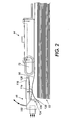
- Figure 1 is a perspective view showing an embodiment of a page-turning device 20 that incorporates features of the present invention. It will become evident from the following discussion that the present invention is equally well suited for use in a wide variety of page turning systems, and is not necessarily limited in its application to the particular system shown herein.
- a book 30 is positioned on a generally V-shaped support, indicated by the reference numeral 32.
- the page-turning device may be combined with a digital camera or digitizing device (not shown) suitable for capturing an image of the pages of the book as or after they are turned.
- Such a system may further include page illumination lamps, optics, a scanning drive, and a scanning array, or other digital or analog image recording means.
- page illumination lamps optics
- a scanning drive and a scanning array, or other digital or analog image recording means.
- Such a system is described in detail in applicant's provisional patent application U.S.S.N. 60/409,399 .
- the turning of the top page of the book in the direction indicated by arrow 38, is performed successively so as to allow the capture of an image of each page.
- the page turning system 20 due to the widely varying page types and conditions encountered in such books (e.g., scanning of the majority of books in a library collection) the page turning system 20 must be able to not only reliably handle such pages, but do so without damage to the pages as well.
- the present invention contemplates the turning of a top page 50 using an articulating arm 60, where the arm would swing once a page had been attracted to the vacuum plenum 64.
- the vacuum plenum is assisted through the use of a fluffer 68, wherein the fluffer is disposed along the edge of the book and is able to eject air so as to disturb the page edges as the top page 50 is being attracted to the plenum.
- a sensor e.g., optical sensor, vacuum pressure sensor, etc.
- the page is turned in the direction indicated by arrow 38 and the vacuum is concurrently reduced so as to assure that the page is not pulled or torn by the plenum.
- a sensing means detects the onset of a loss in vacuum due to the page beginning to loosen from the plenum, and a stronger vacuum is applied to the plenum to maintain the page in contact with the plenum.
- FIG. 2 and 3 there is shown an adaptive fluffer 68.
- Adaptive fluffer 68 has an air inlet opening 102, which is operatively connected to a pressurized air supply source (not shown).
- the adaptive fluffer 68 is arranged such that it may eject air so as to drive some air between the book pages along edge 52 and on the top surface of the top page to be turned.
- the air injected between pages assists with the separation of the pages (i.e., puffs the edge of the pages up).
- the ejected air traveling across the top of page 50 creates, due to a Venturi effect, a vacuum to help pull the page 50 toward the vacuum plenum 64.
- the combined effects of the fluffer 68 are believed to improve the speed of the page separation and thereby facilitate faster turning as well as ensure only a single page is fed.
- Fluffer 68 comprises support structure 110 and a Venturi plate portion 116 and regulating plate portion 120.
- Regulating plate portion 120 has an area 124 that permits air to pass therethrough toward book edge 52, and a cross-section area 126 that restricts air flow.
- the Venturi plate portion 116 is flat against the top sheet 50.
- sheet 50 is fluffed, such upwardly displaced sheet 50 lifts up the Venturi plate portion 116, thereby pivoting the regulating plate 120 of the fluffer 68 around pin 128, and a corresponding pin (not shown) located on the opposite side of fluffer 68.
- the pivoting motion causes the solid cross-section area 126 of regulating plate portion 120 to limit the airflow.
- the Venturi plate 116 is angled relative to support structure 110 so that whatever height the pages are at there remains a gap that maintains the airflow on the book edge to be consistent as the height of the pages changes. Both of these effects regulate the amount of fluffing to prevent over fluffing and keeps pages from being packed near the top page 50. This obviates the problem of pages being packed at the top of the fluffed pages. This problem is more acute in the regular fluffer system for lightweight pages; as it may result in multifeeds. When the sheet 50 is moved out of contact with Venturi plate portion 116, by plenum 64, plate 116 moves back down until it contacts the next page to be turned.
- air plenum 64 is located above the pages 52.
- the air plenum 64 includes a cavity 70 which may be evacuated by a vacuum source (not shown) attached to outlet tube 72, thereby forming a pressure differential.
- the vacuum paper contact surface of the air plenum 64 includes a series of small openings 74. In operation, air flows from cavity 70, through small openings 74, and into the inside of air plenum 64, and then out through outlet tube 72, by the action of the vacuum source (not shown). Thus cavity 70 and small openings 74 are in communication with outlet tube 72 of air plenum 64.
- Paper contact surface 76 is preferably a corrugated surface comprising a combination of varying sized ribs 78 to reduce the bonding forces between page surfaces thereby separating pages on said vacuum paper contact surface 76.
- Seal 80 positioned around the perimeter of plenum 64, is a "floating" and flexible seal between the air plenum and pages.
- An advantage of seal 80 is its adaptability, where it bridges the gap between the air plenum and the top page while not inhibiting the fluffing of the pages as previously described.
- Seal 80 is contoured to the non-flat conditions of the pages as the pages are drawn thereto.
- Seal 80 is also able to contour about a page as the top page is corrugated against the air plenum ribs 78 on the interior of the plenum. Seal 80 is preferably sufficiently rigid so as not to be drawn into the air plenum cavity 70.
- the seal 80 may be movable relative to the plenum or may be a contoured seal that fits the shape of the corrugated surface. A seal including such features would allow the plenum to apply the full vacuum pressure to the page with little or no leakage, thereby lifting the page (the fluffer also assists) until it is drawn into contact with the plenum 64. At this time the page may begin to corrugate around the fixed ridge pattern of the plenum box.
- seals 80 To control the plenum box pressure, it is also possible to design the seals 80 to provide a controlled amount of leakage therethrough.
- the seals are preferably contoured to engage the sheet as it progressively corrugates, yet providing the appropriate leakage to reduce the pressure for lighter weight sheets as is taught in United states patent 6,264,188 .
- seals preferably has a low coefficient of friction with itself and with the material of the plenum body, a high degree of flatness, is lightweight, and is sufficiently rigid so as to resist deformation due to the pressure differential between the ambient external environment and the cavity of the plenum.
- seals were made of polyethylene terephthalate (Mylar®) shim stock.
- air plenum 64 further comprises sensing means to detect the acquisition and sealing of a page thereto.
- sensor means comprises an optical sensor, which detects and confirms that the page is proximate to plenum 64.
- sensing means comprises an air flow or air pressure or vacuum sensor 88 disposed within the interior of plenum 64.
- Sensor 88 may be a strain gage type vacuum sensor, a pitot tube, or a tube connected remotely to a pressure-to-current transducer (not shown).
- sensor 88 may comprise a hot wire anemometer that detects air flow velocity.
- sensor 88 is connected to a controller (not shown), and such controller is further connected to a vacuum source (not shown) that is evacuating plenum 64 through outlet tube 72.
- the controller is programmed with a feedback control loop, so that the vacuum within plenum 64 is modulated so as to prevent damage to the acquired page, such as wrinkling or tearing.
- the controller increases the setpoint of the vacuum source, thereby maintaining the page in an acquired state to plenum 64.
- sensor 88 is located within cavity 70 of plenum 64, located such that sensor 88 does not interfere with the acquisition of a page.
- sensor 88 may be located in proximity to a rib 78, where such sensor would not be contacted by the acquired page.
- concentrated shear forces (P1, P2 and P3 as is disclosed in United States patent 6,264,188 ), will be generated due to the corrugating ribs 78 in the plenum, and these forces will produce shear stress over the cross-section of the paper along the paper thickness direction.
- the shear stress in the vertical direction (the page thickness direction) will be equivalent to the shear stress in the horizontal direction (along the page surface); the shear stress at the center of the beam thickness will be the highest and its value will be inversely proportional to the thickness. Because the beam thickness of the acquired pages is small, a concentrated shear force will generate a large shear stress.
- top page 50 is then acquired by air plenum 64, air plenum 64, attached to upper end of articulating arm 60, is then swung horizontally by articulating arm 60 in an arcuate trajectory as indicated by arcuate arrow 38.
- Articulating arm 60 is pivotally attached at a lower end thereof to base 61 of apparatus 20, and is operated by drive means (not shown), which is operatively engaged with articulating arm 60.
- drive means is described in detail in applicant's aforementioned provisional patent application U.S.S.N. 60/409,399 .
- Top page 50 is thus "turned", i.e. conveyed to the opposite stack 31 of pages of the book 30.
- the vacuum applied to air plenum 64 is released, thereby releasing the newly turned page 50, so that newly turned page 50 becomes the top page 51 of stack 31.
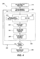
- Figure 4 is a flow chart that depicts stepwise a method of the present invention to turn pages of the book, using the apparatus of the present invention depicted in Figures 1 - 3 .
- the first step 210 of method 200 is the loading and supporting of a book 30 in a generally V-shaped support or cradle 32. With such book 30 open and supported, and the first pages of interest presented, in step 220, such pages may be read by a human (not shown). Alternatively, an image of such pages may be recorded by analog or digital recording means as described in applicant's aforementioned provisional patent application U.S.S.N. 60/409,399 .
- step 262 articulating arm 60 moves air plenum 64 proximate to top page 50 of book 30, as shown in Figure 1 , whereby air plenum 60 is positioned to acquire page 50.
- fluffer 68 is also supplied with air into inlet 102 thereof, thereby "fluffing" or displacing top page 50 upwardly toward air plenum 64, as previously described. Vacuum is then applied to air plenum 64, and top page 50 is acquired by air plenum 64.
- air plenum 64 is then swung horizontally in step 266 by articulating arm 60 as indicated by arcuate arrow 38.
- a sensor 88 (see Figure 3 ) within plenum 64 is used to detect the presence of vacuum therein. In the event that such vacuum exceeds a first programmed setpoint, indicating potential damage to the acquired page, a controller reduces the level of vacuum within plenum 64. In the event that such vacuum drops below a second programmed setpoint, indicating potential loss of the acquired page from the plenum, a controller increases the level of vacuum within plenum 64, thereby retaining the acquired page.
- step 268 When top page 50 is in a position nearly contiguous with stack 31 of pages, the vacuum applied to air plenum 64 is released in step 268, thereby releasing the newly turned page 50 as previously described. If the reading or recording of the pages of book 30 is not complete, as indicated by path 250, the process continues with the repetition of step 220, and the steps of the entire page turning cycle 260, until such reading or recording of book 30 is complete. At such time, book 30 is removed from cradle 32 in step 290.
- steps 210 - 290 of Figure 4 are depicted serially for the sake of simplicity of illustration. It will be apparent that certain of steps 210 - 290 may overlap in time to some extent, thereby optimizing the performance and throughput of applicant's page turning apparatus 20.
- the applicant's page turning apparatus has further utility in the handling of other delicate sheet materials comprising at least one sheet of material disposed on a surface, and attached to or contacting such a surface at one end.
- the page turning apparatus of the present invention may be used in the handling of sheets of fabric in the sewn products industry.
- the page turning apparatus could be used to handle thin sheets of metal foil, without crinkling or tearing such foil.
- the page turning apparatus could be used to handle samples of film such as e.g. photographic film in a development operation.
- the page turning apparatus of the present invention may be adapted to medical procedures.
- the apparatus of the present invention could be used to lift and hold such skin or tissue, and then replace it at the conclusion of surgery. Numerous other uses of the page turning apparatus of the present invention will be apparent to those skilled in the art.
Abstract
Description
- This invention relates generally to a page turning apparatus for use with a book scanning or digitizing system, and more particularly to a page separation mechanism employing a vacuum plenum and corrugated surface thereon.
- The present invention is directed to the application of a vacuum plenum having a corrugated surface as an aid to the separation and turning of pages in an open-book scanner. Scanners of the type in which the present application find a particular use are described, for example, in the United States patents
6,056,258 ,5,640,252 and5,359,207 . - Heretofore, a number of patents have disclosed apparatus and methods of displacing individual sheets of paper from a paper stack and acquiring and moving such sheets of paper. The relevant portions of these patents may be briefly summarized as follows:
- United States patent
6,264,188, of Taylor et al, issued July 24, 2001 , discloses a sheet feeding apparatus having an adaptive air fluffer. The disclosure of this United States patent is incorporated herein by reference. The apparatus comprises a sheet tray for holding a stack of paper sheets, a fluffer for blowing air at the edge of the stack of sheets and displacing an upper sheet upwardly therefrom, an air plenum positioned above the stack of sheets for acquiring the displaced upper sheet of paper and subsequently transporting it to a second location. The paper fluffer is able to adjust air flow between individual sheets in the stack, and includes a support structure, and a plate pivotally mounted in the support structure. The plate has a venturi plate portion in contact with the sheet, and a regulating plate portion with an aperture therein which permits air to pass therethrough, and with a cross sectional area that limits air flow as the sheet moves in contact with the air plenum while pivoting the plate. - In the process of book scanning, a digital image to be scanned or copied is typically obtained by digitizing or imaging the book in an open state. It will be appreciated that while various problems are known In the process of book scanning (e. g., page flatness/depth-of-focus, page turning, book spine handling, etc.) the present invention is directed to an improved apparatus and method for the automated turning of pages in an open book. Although sheet handling system, and the use of vacuum sources are known in high-speed xerographic applications (e. g., United States patent
6,264, 188 ), the present invention is directed to the use of similar technology to assure reliable movement of pages in an open book, where the quality and type of material that the pages are made from varies considerably, both from book-to-book and even from page-to-page. The page handling systems must operate flawlessly to virtually eliminate risk of damaging the pages and generate minimum machine shutdowns due to misfeeds or multifeeds. It is in the initial separation of the individual page from the remaining pages where the greatest numbers of problems occur. Many of the problems to be overcome by an apparatus for the turning of book pages, that is adaptable to a wide range of book sizes, shapes, bindings, and paper properties thereof are further described and illustrated in applicant's co-pendingprovisional application number 60/409,399 -
EP-A-0,779,534 discloses apparatus for imaging books or other bound documents with minimal stress being applied to the book structure, and for successively imaging and turning pages of a book without the need for manual intervention. The book imager includes a support, for placement of a book in an open position, an imager having opposed Imaging surfaces capable of simultaneously imaging the entire exposed, facing adjacent pages of the book in a distortion preventing manner, and a page turner. The support and the imager are relatively movable toward and away from one another, from a first position in which imaging is effected, to a second position in which page turning is effected. This document shows an apparatus according to the preamble of claim 1 and a method according to the preamble of claim 10. - It is therefore an object of this invention to provide a book page turning apparatus that can attach to and turn in sequence every page of a book regardless of the relative quality and type of material that such book pages are made from.
- It is an object of this invention to provide a book page turning apparatus that can attach to and turn in sequence every page of a book regardless of the book size, shape, and binding structure.
- It is a further object of this invention to provide a book page turning apparatus that can attach to and turn in sequence every page of a book, beginning with a selected first page and ending with a selected final page, without interruption due to page misfeeds or multifeeds
- It is an object of this invention to provide a book page turning apparatus that can attach to and turn in sequence every page of a book, without damaging the book.
- In accordance with the present invention as defined in claim 1, there is provided a page turning apparatus for turning at least a top page of a stack of pages in a book, wherein said pages are bound along an edge thereof, comprising: means for holding said book; and an air plenum, positioned above said top page, for picking up said top page when a vacuum is applied to said plenum; and means for moving said air plenum, between a first page location and a second page location so that said top page is turned. The present invention as defined in claim 1 further comprises a paper flutter for blowing air between individual pages of said book, said paper flutter comprising means for adjusting air flow between individual pages, and a regulating plate portion comprising an aperture defined therein that permits air to pass therethrough, said aperture having a cross-sectional area that limits air flow as said top page moves in contact with said air plenum. Additional features are defined in the dependent claims.
- In accordance with the present invention, there is further provided a method for automatically turning the top page of an open book, comprising the steps as defined in claim 10.
- The apparatus and methods presently described are advantageous because they are capable of being adapted to a wide range of books for which it is desired to either view or record images seriatim of the pages therein. In particular, the apparatus of the present invention is capable of reliably separating and turning the pages of a book, and in accommodating the wide variations in geometry between books, as they are held and processed by the apparatus. As a result of the invention, repositories of large volumes of books will have an automated device to assist in the recording, archiving, and distributing the information contained in such books held in such libraries.
- The invention will be described by reference to the following drawings, in which like numerals refer to like elements, and in which:
-
Figure 1 is a perspective view of a page turning system suitable as an embodiment of the present invention; -
Figure 2 is a side view of a paper fluffer and vacuum plenum in accordance with the embodiment ofFigure 1 ; -
Figure 3 is a perspective view of the bottom of a vacuum plenum in accordance with the embodiments ofFigures 1 and2 ; and -
Figure 4 is a flow chart that depicts a method of the present invention to turn pages of the book, using the apparatus of the present invention. - The present invention will be described in connection with a preferred embodiment, however, it will be understood that there is no intent to limit the invention to the embodiment described. On the contrary, the intent is to cover all alternatives and modifications as may be included within the scope of the invention as defined by the appended claims.
- For a general understanding of the present invention, reference is made to the drawings. In the drawings, like reference numerals have been used throughout to designate identical elements.
- By way of a general explanation,
Figure 1 is a perspective view showing an embodiment of a page-turning device 20 that incorporates features of the present invention. It will become evident from the following discussion that the present invention is equally well suited for use in a wide variety of page turning systems, and is not necessarily limited in its application to the particular system shown herein. As shown inFIG. 1 , during operation of the printing system, abook 30 is positioned on a generally V-shaped support, indicated by thereference numeral 32. In one embodiment, the page-turning device may be combined with a digital camera or digitizing device (not shown) suitable for capturing an image of the pages of the book as or after they are turned. Such a system may further include page illumination lamps, optics, a scanning drive, and a scanning array, or other digital or analog image recording means. Such a system is described in detail in applicant's provisional patent applicationU.S.S.N. 60/409,399 - As will be appreciated, the turning of the top page of the book, in the direction indicated by
arrow 38, is performed successively so as to allow the capture of an image of each page. Furthermore, due to the widely varying page types and conditions encountered in such books (e.g., scanning of the majority of books in a library collection) thepage turning system 20 must be able to not only reliably handle such pages, but do so without damage to the pages as well. - The present invention contemplates the turning of a
top page 50 using anarticulating arm 60, where the arm would swing once a page had been attracted to thevacuum plenum 64. In one embodiment, the vacuum plenum is assisted through the use of afluffer 68, wherein the fluffer is disposed along the edge of the book and is able to eject air so as to disturb the page edges as thetop page 50 is being attracted to the plenum. Once the page is grasped by the vacuum applied toplenum 64, perhaps detected by a sensor (e.g., optical sensor, vacuum pressure sensor, etc.), the page is turned in the direction indicated byarrow 38 and the vacuum is concurrently reduced so as to assure that the page is not pulled or torn by the plenum. In a further embodiment, a sensing means detects the onset of a loss in vacuum due to the page beginning to loosen from the plenum, and a stronger vacuum is applied to the plenum to maintain the page in contact with the plenum. - Further details of the construction and operation of the page turning system, and in particular the
vacuum plenum 64 and fluffer 68 of the present invention, are provided below with reference toFigures 2 and3 . Referring toFigures 2 and3 in conjunction withFigure 1 , there is shown anadaptive fluffer 68.Adaptive fluffer 68 has an air inlet opening 102, which is operatively connected to a pressurized air supply source (not shown). Theadaptive fluffer 68 is arranged such that it may eject air so as to drive some air between the book pages alongedge 52 and on the top surface of the top page to be turned. The air injected between pages assists with the separation of the pages (i.e., puffs the edge of the pages up). At the same time, the ejected air traveling across the top ofpage 50 creates, due to a Venturi effect, a vacuum to help pull thepage 50 toward thevacuum plenum 64. The combined effects of thefluffer 68 are believed to improve the speed of the page separation and thereby facilitate faster turning as well as ensure only a single page is fed. - Fluffer 68 comprises
support structure 110 and a Venturiplate portion 116 and regulatingplate portion 120. Regulatingplate portion 120 has anarea 124 that permits air to pass therethrough towardbook edge 52, and across-section area 126 that restricts air flow. Before a page is fluffed, theVenturi plate portion 116 is flat against thetop sheet 50. Whensheet 50 is fluffed, such upwardlydisplaced sheet 50 lifts up theVenturi plate portion 116, thereby pivoting the regulatingplate 120 of thefluffer 68 aroundpin 128, and a corresponding pin (not shown) located on the opposite side offluffer 68. The pivoting motion causes thesolid cross-section area 126 of regulatingplate portion 120 to limit the airflow. - In the embodiment depicted, the
Venturi plate 116 is angled relative to supportstructure 110 so that whatever height the pages are at there remains a gap that maintains the airflow on the book edge to be consistent as the height of the pages changes. Both of these effects regulate the amount of fluffing to prevent over fluffing and keeps pages from being packed near thetop page 50. This obviates the problem of pages being packed at the top of the fluffed pages. This problem is more acute in the regular fluffer system for lightweight pages; as it may result in multifeeds. When thesheet 50 is moved out of contact withVenturi plate portion 116, by plenum 64,plate 116 moves back down until it contacts the next page to be turned. - Referring again to
Figures 2 and3 ,air plenum 64 is located above thepages 52. Theair plenum 64 includes acavity 70 which may be evacuated by a vacuum source (not shown) attached tooutlet tube 72, thereby forming a pressure differential. The vacuum paper contact surface of theair plenum 64 includes a series ofsmall openings 74. In operation, air flows fromcavity 70, throughsmall openings 74, and into the inside ofair plenum 64, and then out throughoutlet tube 72, by the action of the vacuum source (not shown). Thuscavity 70 andsmall openings 74 are in communication withoutlet tube 72 ofair plenum 64. - The difference in pressure between the inside of the
air plenum 64 and the outside ofsuch feeder plenum 64 forces or attracts thetop page 50 toward the vacuumpaper contact surface 76 of thefeeder plenum 64.Paper contact surface 76 is preferably a corrugated surface comprising a combination of varyingsized ribs 78 to reduce the bonding forces between page surfaces thereby separating pages on said vacuumpaper contact surface 76. -
Seal 80, positioned around the perimeter ofplenum 64, is a "floating" and flexible seal between the air plenum and pages. An advantage ofseal 80 is its adaptability, where it bridges the gap between the air plenum and the top page while not inhibiting the fluffing of the pages as previously described.Seal 80 is contoured to the non-flat conditions of the pages as the pages are drawn thereto.Seal 80 is also able to contour about a page as the top page is corrugated against theair plenum ribs 78 on the interior of the plenum.Seal 80 is preferably sufficiently rigid so as not to be drawn into theair plenum cavity 70. - Sealing the
air plenum 64 to the page being acquired has the added advantage that the fluffing air flow does not feed air into the air plenum and make it difficult to create the vacuum required to acquire such page for turning. In yet another embodiment, it is contemplated that theseal 80 may be movable relative to the plenum or may be a contoured seal that fits the shape of the corrugated surface. A seal including such features would allow the plenum to apply the full vacuum pressure to the page with little or no leakage, thereby lifting the page (the fluffer also assists) until it is drawn into contact with theplenum 64. At this time the page may begin to corrugate around the fixed ridge pattern of the plenum box. To control the plenum box pressure, it is also possible to design theseals 80 to provide a controlled amount of leakage therethrough. The seals are preferably contoured to engage the sheet as it progressively corrugates, yet providing the appropriate leakage to reduce the pressure for lighter weight sheets as is taught in United states patent6,264,188 . - The material of construction of such seals preferably has a low coefficient of friction with itself and with the material of the plenum body, a high degree of flatness, is lightweight, and is sufficiently rigid so as to resist deformation due to the pressure differential between the ambient external environment and the cavity of the plenum. In one embodiment, such seals were made of polyethylene terephthalate (Mylar®) shim stock.
- Referring again to
Figure 3 ,air plenum 64 further comprises sensing means to detect the acquisition and sealing of a page thereto. In one embodiment (not shown), sensor means comprises an optical sensor, which detects and confirms that the page is proximate toplenum 64. In the embodiment depicted inFigure 3 , sensing means comprises an air flow or air pressure orvacuum sensor 88 disposed within the interior ofplenum 64.Sensor 88 may be a strain gage type vacuum sensor, a pitot tube, or a tube connected remotely to a pressure-to-current transducer (not shown). In an alternate embodiment,sensor 88 may comprise a hot wire anemometer that detects air flow velocity. It is known that air flow within a plenum is easily correlated with vacuum or pressure within a plenum, such that an air flow sensor is functionally equivalent to a vacuum or pressure sensor. It will be apparent that numerous other sensing means that detect air pressure, vacuum, and/or flow rate will be suitable. - In operation,
sensor 88 is connected to a controller (not shown), and such controller is further connected to a vacuum source (not shown) that is evacuatingplenum 64 throughoutlet tube 72. The controller is programmed with a feedback control loop, so that the vacuum withinplenum 64 is modulated so as to prevent damage to the acquired page, such as wrinkling or tearing. In the event that a loss of vacuum is detected, indicating the onset of a loss of the acquired page, the controller increases the setpoint of the vacuum source, thereby maintaining the page in an acquired state to plenum 64. - It will be apparent that the location shown of
sensor 88 withinplenum 64 is for illustrative purposes only, and that many other locations withinplenum 64 would be suitable. In an alternate embodiment,sensor 88 is located withincavity 70 ofplenum 64, located such thatsensor 88 does not interfere with the acquisition of a page. For example,sensor 88 may be located in proximity to arib 78, where such sensor would not be contacted by the acquired page. - In accordance with one embodiment of the present invention, when the top sheet is acquired, concentrated shear forces, (P1, P2 and P3 as is disclosed in United States patent
6,264,188 ), will be generated due to thecorrugating ribs 78 in the plenum, and these forces will produce shear stress over the cross-section of the paper along the paper thickness direction. As a result, the shear stress in the vertical direction (the page thickness direction) will be equivalent to the shear stress in the horizontal direction (along the page surface); the shear stress at the center of the beam thickness will be the highest and its value will be inversely proportional to the thickness. Because the beam thickness of the acquired pages is small, a concentrated shear force will generate a large shear stress. Thus, if more than one page is acquired, the shear stress will work to slide the page over the surface of pages beneath. A gap between the pages is therefore initiated if the strength of the paper bond at those stressed locations is weaker than the sliding force. Besides producing a shear force, bending of the page also helps initiate gaps between the pages. When a beam is bent, the upper and lower parts of the beam undergo different kinds of deformation; one part is in expansion and the other in compression. Therefore, if a plurality of pages are bent simultaneously, the bending motion will help separate the pages. - Referring again to
Figure 1 , at such time as thetop page 50 has been acquired byair plenum 64,air plenum 64, attached to upper end of articulatingarm 60, is then swung horizontally by articulatingarm 60 in an arcuate trajectory as indicated byarcuate arrow 38. Articulatingarm 60 is pivotally attached at a lower end thereof tobase 61 ofapparatus 20, and is operated by drive means (not shown), which is operatively engaged with articulatingarm 60. Such drive means is described in detail in applicant's aforementioned provisional patent applicationU.S.S.N. 60/409,399 Top page 50 is thus "turned", i.e. conveyed to theopposite stack 31 of pages of thebook 30. Astop page 50 is moved to a position nearly contiguous withstack 31 of pages, the vacuum applied toair plenum 64 is released, thereby releasing the newly turnedpage 50, so that newly turnedpage 50 becomes thetop page 51 ofstack 31. -
Figure 4 is a flow chart that depicts stepwise a method of the present invention to turn pages of the book, using the apparatus of the present invention depicted inFigures 1 - 3 . Referring initially toFigure 1 andFigure 4 , thefirst step 210 ofmethod 200 is the loading and supporting of abook 30 in a generally V-shaped support orcradle 32. Withsuch book 30 open and supported, and the first pages of interest presented, instep 220, such pages may be read by a human (not shown). Alternatively, an image of such pages may be recorded by analog or digital recording means as described in applicant's aforementioned provisional patent applicationU.S.S.N. 60/409,399 - Subsequently, in
step 262, articulatingarm 60moves air plenum 64 proximate totop page 50 ofbook 30, as shown inFigure 1 , wherebyair plenum 60 is positioned to acquirepage 50. Referring toFigure 2 , in a preferred embodiment further comprisingstep 261,fluffer 68 is also supplied with air intoinlet 102 thereof, thereby "fluffing" or displacingtop page 50 upwardly towardair plenum 64, as previously described. Vacuum is then applied toair plenum 64, andtop page 50 is acquired byair plenum 64. - Referring again to
Figure 1 andFigure 4 ,air plenum 64 is then swung horizontally instep 266 by articulatingarm 60 as indicated byarcuate arrow 38. During this motion, in one embodiment, a sensor 88 (seeFigure 3 ) withinplenum 64 is used to detect the presence of vacuum therein. In the event that such vacuum exceeds a first programmed setpoint, indicating potential damage to the acquired page, a controller reduces the level of vacuum withinplenum 64. In the event that such vacuum drops below a second programmed setpoint, indicating potential loss of the acquired page from the plenum, a controller increases the level of vacuum withinplenum 64, thereby retaining the acquired page. - When
top page 50 is in a position nearly contiguous withstack 31 of pages, the vacuum applied toair plenum 64 is released instep 268, thereby releasing the newly turnedpage 50 as previously described. If the reading or recording of the pages ofbook 30 is not complete, as indicated bypath 250, the process continues with the repetition ofstep 220, and the steps of the entirepage turning cycle 260, until such reading or recording ofbook 30 is complete. At such time,book 30 is removed fromcradle 32 instep 290. - It is to be understood that steps 210 - 290 of
Figure 4 are depicted serially for the sake of simplicity of illustration. It will be apparent that certain of steps 210 - 290 may overlap in time to some extent, thereby optimizing the performance and throughput of applicant'spage turning apparatus 20. - It is to be further understood that the applicant's page turning apparatus has further utility in the handling of other delicate sheet materials comprising at least one sheet of material disposed on a surface, and attached to or contacting such a surface at one end. For example, the page turning apparatus of the present invention may be used in the handling of sheets of fabric in the sewn products industry. In another embodiment, the page turning apparatus could be used to handle thin sheets of metal foil, without crinkling or tearing such foil. In another embodiment, the page turning apparatus could be used to handle samples of film such as e.g. photographic film in a development operation.
- In another embodiment, the page turning apparatus of the present invention may be adapted to medical procedures. For example, in a surgical operation, where there is a need to gently and aseptically displace a flap of skin or other tissue without contact by the surgeon, the apparatus of the present invention could be used to lift and hold such skin or tissue, and then replace it at the conclusion of surgery. Numerous other uses of the page turning apparatus of the present invention will be apparent to those skilled in the art.
- It is, therefore, apparent that there has been provided, in accordance with the present invention, a method and apparatus for the turning of pages, wherein the pages may be separated with an air fluffer and acquired for turning using a vacuum, corrugated plenum. While this invention has been described in conjunction with preferred embodiments thereof, it is evident that many alternatives, modifications, and variations will be apparent to those skilled in the art. Accordingly, it is intended to embrace all such alternatives, modifications and variations that fall within the scope of the appended claims.
Claims (10)
- A page turning apparatus (20) for turning at least a top page (50) of a stack of pages in a book (3), wherein said pages are bound along an edge thereof, comprising:a) means (32) for holding said book; andb) an air plenum (64), positioned above said top page, for picking up said top page when a vacuum is applied to said plenum; andc) means (60) for moving said air plenum, between a first page location and a second page location so that said top page is turned;
further comprising a paper fluffer (68) for blowing air between individual pages of said book, said paper fluffer comprising:a) means (116) for adjusting air flow between said individual pages; and characterised in that the paper fluffer comprises:b) a regulating plate portion (120) comprising an aperture defined therein that permits air to pass therethrough, said aperture having a cross-sectional area (126) that limits air flow as said top page moves in contact with said air plenum. - A page turning apparatus as claimed in claim 1, wherein said air plenum further comprises a cavity (70), and a paper contact surface (76) including a corrugated surface having a plurality of openings (74) and a combination of varying sized ribs (78).
- A page turning apparatus as claimed in claim 2, wherein at least two of said varying sized ribs are parallel to each other.
- A page turning apparatus as claimed in claim 2, wherein said air plenum further comprises an outlet tube (72) that is in communication with said plurality of openings (74) and with said cavity (70).
- A page turning apparatus as claimed in claim 4, wherein said air plenum further comprises a perimeter, and a flexible seal (80) disposed around said perimeter.
- A page turning apparatus as claimed in claim 5, wherein said seal (80) is contoured to said top page acquired thereto.
- A page turning apparatus as claimed in claim 2, wherein said air plenum further comprises vacuum sensing means (88) disposed therein.
- A page turning apparatus as claimed in any preceding claim, wherein said apparatus further comprises a base (61), and wherein said means for moving said air plenum comprises an articulating arm (60) comprised of an upper end and a lower end, said lower end of said articulating arm is attached to said base of said apparatus, and said air plenum is attached to said upper end of said articulating arm.
- A page turning apparatus as claimed in claim 1, wherein said apparatus further comprises a base, and wherein said means for holding said book comprises a V-shaped support (32) disposed upon said base.
- A method for automatically turning the top page of an open book, comprising the steps of:a) supporting said book in an open position (210);b) moving an air plenum Into proximity with a top page of said book (262);c) applying a vacuum to said air plenum (264) so as to cause at least said top page to be attracted thereto;d) moving said air plenum from a first position in proximity to said top page to a second position toward an opposite page (266); ande) releasing said vacuum to said air plenum (268) so as to cause said top page to fall to a position on top of said opposite page, thereby turning said top page;f) said method further comprising the step of engaging an air source to a paper fluffer (261) located adjacent the end of the at least said top page so as to cause said top page to be separated from pages therebelow;
characterised in the method further comprising the step of reducing said vacuum to said air plenum concurrently with said moving said air plenum from said first position to said second position.
Applications Claiming Priority (3)
| Application Number | Priority Date | Filing Date | Title |
|---|---|---|---|
| US36488902P | 2002-03-15 | 2002-03-15 | |
| US364889P | 2002-03-15 | ||
| PCT/US2003/008052 WO2003078176A2 (en) | 2002-03-15 | 2003-03-14 | Page turning apparatus with a vacuum plenum and an adaptive air fluffer |
Publications (3)
| Publication Number | Publication Date |
|---|---|
| EP1490777A2 EP1490777A2 (en) | 2004-12-29 |
| EP1490777A4 EP1490777A4 (en) | 2006-05-10 |
| EP1490777B1 true EP1490777B1 (en) | 2011-05-18 |
Family
ID=28041980
Family Applications (1)
| Application Number | Title | Priority Date | Filing Date |
|---|---|---|---|
| EP03728250A Expired - Lifetime EP1490777B1 (en) | 2002-03-15 | 2003-03-14 | Page turning apparatus with a vacuum plenum and an adaptive air fluffer |
Country Status (7)
| Country | Link |
|---|---|
| US (1) | US7595915B2 (en) |
| EP (1) | EP1490777B1 (en) |
| CN (1) | CN1653438B (en) |
| AT (1) | ATE510256T1 (en) |
| AU (1) | AU2003233403A1 (en) |
| HK (1) | HK1072637A1 (en) |
| WO (1) | WO2003078176A2 (en) |
Families Citing this family (19)
| Publication number | Priority date | Publication date | Assignee | Title |
|---|---|---|---|---|
| EP1540942A4 (en) * | 2002-09-10 | 2006-01-11 | Kirtas Technologies Inc | Automated page turning apparatus to assist in viewing pages of a document |
| CN101108046B (en) * | 2002-10-18 | 2010-08-04 | 株式会社不二宫制作所 | Reading device |
| KR100871855B1 (en) * | 2006-12-01 | 2008-12-03 | 정승태 | The scanner for book, that using digital camera |
| US20080265493A1 (en) * | 2007-04-30 | 2008-10-30 | Robert Wall | Air delivery device for printing and coating applications |
| WO2008157764A1 (en) * | 2007-06-21 | 2008-12-24 | Kirtas Technologies, Inc. | Automated page turning apparatus to assist in viewing pages of a document |
| US20090180085A1 (en) * | 2008-01-15 | 2009-07-16 | Kirtas Technologies, Inc. | System and method for large format imaging |
| FR2940260B1 (en) * | 2008-12-19 | 2010-12-24 | Maf Agrobotic | DEVICE FOR TREATING AT LEAST ONE FLEXIBLE ARTICLES WITH AT LEAST ONE DELIASSEUR |
| DE102009050910A1 (en) * | 2009-10-26 | 2011-05-05 | Bundesdruckerei Gmbh | Mechanical sheet module |
| US8711448B1 (en) * | 2011-10-06 | 2014-04-29 | Google Inc. | Linear book scanner |
| US8531740B1 (en) * | 2012-02-23 | 2013-09-10 | Tomasz Wardega | Universal scanning stand for devices equipped with a digital camera |
| JP5929736B2 (en) | 2012-12-18 | 2016-06-08 | カシオ計算機株式会社 | Page turning apparatus, document camera system, and method |
| US9030718B1 (en) * | 2014-03-20 | 2015-05-12 | Foxlink Image Technology Co., Ltd. | Book scanner |
| US9591168B2 (en) * | 2015-07-17 | 2017-03-07 | Ecole Polytechnique Federale De Lausanne (Epfl) | Apparatus for imaging a page of a book or other similar document |
| US9906664B2 (en) | 2015-12-30 | 2018-02-27 | Kodak Alaris Inc. | Mobile autonomous scalable scanner system |
| US9936089B2 (en) | 2015-12-30 | 2018-04-03 | Kodak Alaris Inc. | Mobile autonomous scalable scanner system |
| CN107554127A (en) * | 2017-09-20 | 2018-01-09 | 长春理工大学光电信息学院 | A kind of foot-operated automatic book page turning machine and its control method |
| DE102018103632A1 (en) * | 2018-02-19 | 2019-08-22 | Bundesdruckerei Gmbh | Apparatus, system and method for opening or browsing a book-type security document |
| US10931835B1 (en) * | 2018-09-24 | 2021-02-23 | Steve Octavien | Print media scanning system |
| CN110381226B (en) * | 2019-07-19 | 2021-08-03 | 斯卡纳(北京)科技有限公司 | Scanner |
Family Cites Families (62)
| Publication number | Priority date | Publication date | Assignee | Title |
|---|---|---|---|---|
| DE242884C (en) | ||||
| US2065011A (en) * | 1935-09-24 | 1936-12-22 | Harry P Wills | Record book photographing appliance |
| US2555186A (en) * | 1948-01-21 | 1951-05-29 | Telesphore C Demers | Page turner |
| US3016036A (en) * | 1960-05-04 | 1962-01-09 | Walter T Jorgensen | Place-holding device for books |
| DE1561371A1 (en) | 1967-04-29 | 1970-02-12 | Werner Schwartz | Page turning device for stacks of sheets bound on one side |
| US3484970A (en) * | 1968-03-22 | 1969-12-23 | Commerce Usa | Automatic sheet turner using a rotating vacuum head |
| US3550296A (en) * | 1968-09-03 | 1970-12-29 | John F Castagna | Page turning device |
| US3519264A (en) | 1969-06-25 | 1970-07-07 | Clement Co J W | Collating system with malfunction control |
| NL159615B (en) * | 1972-04-27 | 1979-03-15 | Stichting Revalidatie Res | LEAF FOLDER. |
| US3816646A (en) * | 1972-08-24 | 1974-06-11 | Opaque Syst Ltd | Television enlarging and display apparatus for graphic copy |
| SE376390B (en) * | 1973-02-08 | 1975-05-26 | Weststrom Jan Hakan | |
| US4121361A (en) * | 1976-03-24 | 1978-10-24 | Arcy James A D | Apparatus for automatically turning pages |
| GB2010229B (en) | 1977-11-25 | 1982-03-17 | Quest Educational Designs Ltd | Page turning device |
| JPS56120276U (en) * | 1980-02-14 | 1981-09-12 | ||
| JPS5820498A (en) * | 1981-07-31 | 1983-02-05 | 株式会社東芝 | Page turning-over device for booklets |
| US4432154A (en) * | 1982-03-08 | 1984-02-21 | Dejon Corporation | Page manipulation apparatus in apparatus for automatically turning pages |
| US4566683A (en) * | 1983-08-26 | 1986-01-28 | Xerox Corporation | Sheet feeding apparatus and valve therefor |
| JPS6079998A (en) * | 1983-09-30 | 1985-05-07 | エヌ・シー・アール・インターナショナル・インコーポレイテッド | Page turn-over device for booklets |
| US4644675A (en) * | 1985-02-11 | 1987-02-24 | Regents Of The University Of Minnesota | Page turning device |
| JPS61228995A (en) | 1985-04-02 | 1986-10-13 | 富士通株式会社 | Page turning-over device |
| US4731667A (en) * | 1985-07-15 | 1988-03-15 | Kabushiki Kaisha Toshiba | Image forming apparatus |
| US4942482A (en) * | 1985-08-09 | 1990-07-17 | Sony Corporation | Automatic page-turning device |
| US4673286A (en) * | 1985-12-20 | 1987-06-16 | Xerox Corporation | Frictionless vacuum feeder for book copying |
| US4663873A (en) * | 1985-12-20 | 1987-05-12 | Xerox Corporation | Page flipper for book copying |
| US5247755A (en) * | 1987-04-08 | 1993-09-28 | Canon Kabushiki Kaisha | Automatic page turning-over apparatus |
| JPS645891A (en) * | 1987-06-29 | 1989-01-10 | Sony Corp | Page turn-over device |
| US4899214A (en) * | 1988-09-02 | 1990-02-06 | Itek Graphic Corp. | Low cost color scanner |
| US4936034A (en) | 1989-02-04 | 1990-06-26 | Chen Chieh Ju | Reading stand with page turning mechanism |
| US5390033A (en) * | 1991-07-19 | 1995-02-14 | Ricoh Company, Ltd. | Method and apparatus for turning over pages of book-original |
| JP3413221B2 (en) * | 1991-12-27 | 2003-06-03 | 株式会社リコー | Image reading device |
| US5493943A (en) * | 1992-04-23 | 1996-02-27 | Sharp Kabushiki Kaisha | Page turner |
| US5351927A (en) * | 1992-12-07 | 1994-10-04 | Howell Richard J | Book holder for use with stand assemblies |
| JP3302761B2 (en) * | 1993-02-24 | 2002-07-15 | 株式会社リコー | Book Scanner |
| JP3293939B2 (en) * | 1993-04-05 | 2002-06-17 | 株式会社リコー | Page turning device for book manuscript |
| US5359207A (en) * | 1993-11-29 | 1994-10-25 | Xerox Corporation | Wedge scanner utilizing two dimensional sensing arrays |
| JP3471955B2 (en) | 1994-04-28 | 2003-12-02 | 株式会社リコー | Book Scanner |
| JPH08154157A (en) * | 1994-11-28 | 1996-06-11 | Ricoh Co Ltd | Book source document image reader |
| US5612791A (en) * | 1995-12-12 | 1997-03-18 | Xerox Corporation | Bound document imager with air jet page turning system |
| US5640252A (en) | 1995-12-12 | 1997-06-17 | Xerox Corporation | Bound document imager with page turner |
| JP3436025B2 (en) * | 1995-12-27 | 2003-08-11 | ミノルタ株式会社 | Correction method of read image and image reading device |
| US5777660A (en) * | 1996-02-26 | 1998-07-07 | Ricoh Company, Ltd. | Scanner assembly |
| US5979940A (en) * | 1996-09-09 | 1999-11-09 | Araghi; Behrooz | Book holder |
| FR2757797B1 (en) | 1996-12-30 | 1999-02-05 | Frontalini Amedeo | AUTOMATIC PAGE TURN |
| JP3792823B2 (en) * | 1997-02-28 | 2006-07-05 | キヤノン株式会社 | Printing apparatus and printing control apparatus |
| US5967507A (en) * | 1997-04-14 | 1999-10-19 | Xerox Corporation | Automatic document handler having non-relative motion vacuum corrugating device |
| US6058258A (en) * | 1997-10-28 | 2000-05-02 | International Business Machines Corporation | Method for analyzing the stability and passivity of system models |
| US6056258A (en) | 1998-12-08 | 2000-05-02 | Xerox Corporation | Bound document imager |
| US6459505B1 (en) | 1998-12-08 | 2002-10-01 | Xerox Corporation | Bound document imager |
| US6186492B1 (en) * | 1998-12-23 | 2001-02-13 | Xerox Corporation | Adjusting air system pressures stack height and lead edge gap in high capacity feeder |
| JP3528168B2 (en) * | 1999-03-31 | 2004-05-17 | 船井電機株式会社 | Light control device |
| US6279896B1 (en) * | 1999-10-12 | 2001-08-28 | Xerox Corporation | Systems and methods for dynamically setting air system pressures based on real time sheet acquisition time data |
| US6398208B1 (en) | 2000-06-12 | 2002-06-04 | Xerox Corporation | Sheet feeding apparatus having an air plenum with a leaky seal |
| US6398206B1 (en) * | 2000-06-12 | 2002-06-04 | Xerox Corporation | Sheet feeding apparatus having an air plenum with a corrugated surface |
| US6264188B1 (en) * | 2000-06-12 | 2001-07-24 | Xerox Corporation | Sheet feeding apparatus having an adaptive air fluffer |
| AU2002308651A1 (en) * | 2001-05-04 | 2002-11-18 | Leberl, Franz, W. | Digital camera for and method of obtaining overlapping images |
| US7046401B2 (en) * | 2001-06-01 | 2006-05-16 | Hewlett-Packard Development Company, L.P. | Camera-based document scanning system using multiple-pass mosaicking |
| CH694526A5 (en) | 2001-08-13 | 2005-03-15 | Assy Sa | Automatic device for turning the pages of a book, in particular a book, a magazine or a binder |
| US6611362B2 (en) * | 2001-09-28 | 2003-08-26 | Xerox Corporation | Automatic book page turner for imaging |
| US6574014B2 (en) * | 2001-09-28 | 2003-06-03 | Xerox Corporation | Automatic book page turner for imaging |
| US7474399B2 (en) * | 2002-02-22 | 2009-01-06 | Xenogen Corporation | Dual illumination system for an imaging apparatus and method |
| EP1540942A4 (en) * | 2002-09-10 | 2006-01-11 | Kirtas Technologies Inc | Automated page turning apparatus to assist in viewing pages of a document |
| WO2008157764A1 (en) * | 2007-06-21 | 2008-12-24 | Kirtas Technologies, Inc. | Automated page turning apparatus to assist in viewing pages of a document |
-
2003
- 2003-03-14 AU AU2003233403A patent/AU2003233403A1/en not_active Abandoned
- 2003-03-14 US US10/389,051 patent/US7595915B2/en not_active Expired - Fee Related
- 2003-03-14 CN CN03810833.XA patent/CN1653438B/en not_active Expired - Fee Related
- 2003-03-14 EP EP03728250A patent/EP1490777B1/en not_active Expired - Lifetime
- 2003-03-14 AT AT03728250T patent/ATE510256T1/en active
- 2003-03-14 WO PCT/US2003/008052 patent/WO2003078176A2/en not_active Application Discontinuation
-
2005
- 2005-06-28 HK HK05105384.8A patent/HK1072637A1/en not_active IP Right Cessation
Also Published As
| Publication number | Publication date |
|---|---|
| ATE510256T1 (en) | 2011-06-15 |
| AU2003233403A8 (en) | 2003-09-29 |
| US7595915B2 (en) | 2009-09-29 |
| AU2003233403A1 (en) | 2003-09-29 |
| US20030172795A1 (en) | 2003-09-18 |
| HK1072637A1 (en) | 2005-09-02 |
| CN1653438B (en) | 2010-05-26 |
| WO2003078176A2 (en) | 2003-09-25 |
| EP1490777A4 (en) | 2006-05-10 |
| WO2003078176A3 (en) | 2004-02-19 |
| EP1490777A2 (en) | 2004-12-29 |
| CN1653438A (en) | 2005-08-10 |
Similar Documents
| Publication | Publication Date | Title |
|---|---|---|
| EP1490777B1 (en) | Page turning apparatus with a vacuum plenum and an adaptive air fluffer | |
| US6611362B2 (en) | Automatic book page turner for imaging | |
| EP1438835B2 (en) | Automatic book page turner for imaging | |
| US7557965B2 (en) | Automated page turning apparatus to assist in viewing pages of a document | |
| US20060044631A1 (en) | Automatic device for turning the pages of a bound document | |
| JP4050349B2 (en) | Book imager | |
| JP3730342B2 (en) | Book imager and book page image forming method | |
| KR101654642B1 (en) | Page-turning reader device and feeder device | |
| JPS5895046A (en) | Sheet feeder | |
| US20080316551A1 (en) | Automated page turning apparatus to assist in viewing pages of a document | |
| WO2019080890A1 (en) | Extremely fast scanner and page separating device | |
| US5971393A (en) | Device and method for loading and unloading a sheet-like medium | |
| JP4520071B2 (en) | Paper feeding device and image forming apparatus | |
| JPH072536B2 (en) | Bottom sheet separating / feeding device | |
| US7440148B2 (en) | System for manipulating pages of a material | |
| JPH0354348B2 (en) | ||
| US5899449A (en) | Top vacuum corrugation feeder with articulating suction fingers | |
| US8388245B2 (en) | Incorporated printer with separate-sheet printing and book printing capabilities | |
| WO2007136242A1 (en) | Method and device for unstacking a stack of flexible sheets | |
| JPH09118446A (en) | Device to facilitate handling of sheet with tab in top feeding type suction type corrugated feeder | |
| EP1762518A1 (en) | A sheet feed method, a sheet feeder, and an image forming apparatus incorporating the said feeder | |
| JPH0367828A (en) | Paper feeder |
Legal Events
| Date | Code | Title | Description |
|---|---|---|---|
| PUAI | Public reference made under article 153(3) epc to a published international application that has entered the european phase |
Free format text: ORIGINAL CODE: 0009012 |
|
| 17P | Request for examination filed |
Effective date: 20041012 |
|
| AK | Designated contracting states |
Kind code of ref document: A2 Designated state(s): AT BE BG CH CY CZ DE DK EE ES FI FR GB GR HU IE IT LI LU MC NL PT RO SE SI SK TR |
|
| AX | Request for extension of the european patent |
Extension state: AL LT LV MK |
|
| REG | Reference to a national code |
Ref country code: HK Ref legal event code: DE Ref document number: 1072637 Country of ref document: HK |
|
| A4 | Supplementary search report drawn up and despatched |
Effective date: 20060327 |
|
| 17Q | First examination report despatched |
Effective date: 20091016 |
|
| GRAJ | Information related to disapproval of communication of intention to grant by the applicant or resumption of examination proceedings by the epo deleted |
Free format text: ORIGINAL CODE: EPIDOSDIGR1 |
|
| GRAP | Despatch of communication of intention to grant a patent |
Free format text: ORIGINAL CODE: EPIDOSNIGR1 |
|
| GRAS | Grant fee paid |
Free format text: ORIGINAL CODE: EPIDOSNIGR3 |
|
| GRAA | (expected) grant |
Free format text: ORIGINAL CODE: 0009210 |
|
| AK | Designated contracting states |
Kind code of ref document: B1 Designated state(s): AT BE BG CH CY CZ DE DK EE ES FI FR GB GR HU IE IT LI LU MC NL PT RO SE SI SK TR |
|
| REG | Reference to a national code |
Ref country code: GB Ref legal event code: FG4D |
|
| REG | Reference to a national code |
Ref country code: CH Ref legal event code: EP |
|
| REG | Reference to a national code |
Ref country code: IE Ref legal event code: FG4D |
|
| REG | Reference to a national code |
Ref country code: CH Ref legal event code: NV Representative=s name: ISLER & PEDRAZZINI AG Ref country code: DE Ref legal event code: R096 Ref document number: 60337150 Country of ref document: DE Effective date: 20110630 |
|
| REG | Reference to a national code |
Ref country code: NL Ref legal event code: VDEP Effective date: 20110518 |
|
| REG | Reference to a national code |
Ref country code: HK Ref legal event code: GR Ref document number: 1072637 Country of ref document: HK |
|
| PG25 | Lapsed in a contracting state [announced via postgrant information from national office to epo] |
Ref country code: PT Free format text: LAPSE BECAUSE OF FAILURE TO SUBMIT A TRANSLATION OF THE DESCRIPTION OR TO PAY THE FEE WITHIN THE PRESCRIBED TIME-LIMIT Effective date: 20110919 Ref country code: SE Free format text: LAPSE BECAUSE OF FAILURE TO SUBMIT A TRANSLATION OF THE DESCRIPTION OR TO PAY THE FEE WITHIN THE PRESCRIBED TIME-LIMIT Effective date: 20110518 |
|
| PG25 | Lapsed in a contracting state [announced via postgrant information from national office to epo] |
Ref country code: SI Free format text: LAPSE BECAUSE OF FAILURE TO SUBMIT A TRANSLATION OF THE DESCRIPTION OR TO PAY THE FEE WITHIN THE PRESCRIBED TIME-LIMIT Effective date: 20110518 Ref country code: GR Free format text: LAPSE BECAUSE OF FAILURE TO SUBMIT A TRANSLATION OF THE DESCRIPTION OR TO PAY THE FEE WITHIN THE PRESCRIBED TIME-LIMIT Effective date: 20110819 Ref country code: CY Free format text: LAPSE BECAUSE OF FAILURE TO SUBMIT A TRANSLATION OF THE DESCRIPTION OR TO PAY THE FEE WITHIN THE PRESCRIBED TIME-LIMIT Effective date: 20110518 Ref country code: ES Free format text: LAPSE BECAUSE OF FAILURE TO SUBMIT A TRANSLATION OF THE DESCRIPTION OR TO PAY THE FEE WITHIN THE PRESCRIBED TIME-LIMIT Effective date: 20110829 Ref country code: FI Free format text: LAPSE BECAUSE OF FAILURE TO SUBMIT A TRANSLATION OF THE DESCRIPTION OR TO PAY THE FEE WITHIN THE PRESCRIBED TIME-LIMIT Effective date: 20110518 Ref country code: BE Free format text: LAPSE BECAUSE OF FAILURE TO SUBMIT A TRANSLATION OF THE DESCRIPTION OR TO PAY THE FEE WITHIN THE PRESCRIBED TIME-LIMIT Effective date: 20110518 |
|
| PG25 | Lapsed in a contracting state [announced via postgrant information from national office to epo] |
Ref country code: NL Free format text: LAPSE BECAUSE OF FAILURE TO SUBMIT A TRANSLATION OF THE DESCRIPTION OR TO PAY THE FEE WITHIN THE PRESCRIBED TIME-LIMIT Effective date: 20110518 |
|
| PG25 | Lapsed in a contracting state [announced via postgrant information from national office to epo] |
Ref country code: EE Free format text: LAPSE BECAUSE OF FAILURE TO SUBMIT A TRANSLATION OF THE DESCRIPTION OR TO PAY THE FEE WITHIN THE PRESCRIBED TIME-LIMIT Effective date: 20110518 Ref country code: CZ Free format text: LAPSE BECAUSE OF FAILURE TO SUBMIT A TRANSLATION OF THE DESCRIPTION OR TO PAY THE FEE WITHIN THE PRESCRIBED TIME-LIMIT Effective date: 20110518 |
|
| PG25 | Lapsed in a contracting state [announced via postgrant information from national office to epo] |
Ref country code: DK Free format text: LAPSE BECAUSE OF FAILURE TO SUBMIT A TRANSLATION OF THE DESCRIPTION OR TO PAY THE FEE WITHIN THE PRESCRIBED TIME-LIMIT Effective date: 20110518 Ref country code: SK Free format text: LAPSE BECAUSE OF FAILURE TO SUBMIT A TRANSLATION OF THE DESCRIPTION OR TO PAY THE FEE WITHIN THE PRESCRIBED TIME-LIMIT Effective date: 20110518 Ref country code: RO Free format text: LAPSE BECAUSE OF FAILURE TO SUBMIT A TRANSLATION OF THE DESCRIPTION OR TO PAY THE FEE WITHIN THE PRESCRIBED TIME-LIMIT Effective date: 20110518 |
|
| PLBE | No opposition filed within time limit |
Free format text: ORIGINAL CODE: 0009261 |
|
| STAA | Information on the status of an ep patent application or granted ep patent |
Free format text: STATUS: NO OPPOSITION FILED WITHIN TIME LIMIT |
|
| 26N | No opposition filed |
Effective date: 20120221 |
|
| PG25 | Lapsed in a contracting state [announced via postgrant information from national office to epo] |
Ref country code: IT Free format text: LAPSE BECAUSE OF FAILURE TO SUBMIT A TRANSLATION OF THE DESCRIPTION OR TO PAY THE FEE WITHIN THE PRESCRIBED TIME-LIMIT Effective date: 20110518 |
|
| REG | Reference to a national code |
Ref country code: DE Ref legal event code: R097 Ref document number: 60337150 Country of ref document: DE Effective date: 20120221 |
|
| PG25 | Lapsed in a contracting state [announced via postgrant information from national office to epo] |
Ref country code: MC Free format text: LAPSE BECAUSE OF NON-PAYMENT OF DUE FEES Effective date: 20120331 |
|
| REG | Reference to a national code |
Ref country code: CH Ref legal event code: PL |
|
| GBPC | Gb: european patent ceased through non-payment of renewal fee |
Effective date: 20120314 |
|
| REG | Reference to a national code |
Ref country code: IE Ref legal event code: MM4A |
|
| PG25 | Lapsed in a contracting state [announced via postgrant information from national office to epo] |
Ref country code: LI Free format text: LAPSE BECAUSE OF NON-PAYMENT OF DUE FEES Effective date: 20120331 Ref country code: CH Free format text: LAPSE BECAUSE OF NON-PAYMENT OF DUE FEES Effective date: 20120331 Ref country code: GB Free format text: LAPSE BECAUSE OF NON-PAYMENT OF DUE FEES Effective date: 20120314 Ref country code: IE Free format text: LAPSE BECAUSE OF NON-PAYMENT OF DUE FEES Effective date: 20120314 |
|
| REG | Reference to a national code |
Ref country code: AT Ref legal event code: MM01 Ref document number: 510256 Country of ref document: AT Kind code of ref document: T Effective date: 20120314 |
|
| PG25 | Lapsed in a contracting state [announced via postgrant information from national office to epo] |
Ref country code: BG Free format text: LAPSE BECAUSE OF FAILURE TO SUBMIT A TRANSLATION OF THE DESCRIPTION OR TO PAY THE FEE WITHIN THE PRESCRIBED TIME-LIMIT Effective date: 20110818 |
|
| PG25 | Lapsed in a contracting state [announced via postgrant information from national office to epo] |
Ref country code: AT Free format text: LAPSE BECAUSE OF NON-PAYMENT OF DUE FEES Effective date: 20120314 |
|
| PG25 | Lapsed in a contracting state [announced via postgrant information from national office to epo] |
Ref country code: TR Free format text: LAPSE BECAUSE OF FAILURE TO SUBMIT A TRANSLATION OF THE DESCRIPTION OR TO PAY THE FEE WITHIN THE PRESCRIBED TIME-LIMIT Effective date: 20110518 |
|
| PGFP | Annual fee paid to national office [announced via postgrant information from national office to epo] |
Ref country code: DE Payment date: 20140319 Year of fee payment: 12 |
|
| PG25 | Lapsed in a contracting state [announced via postgrant information from national office to epo] |
Ref country code: LU Free format text: LAPSE BECAUSE OF NON-PAYMENT OF DUE FEES Effective date: 20120314 |
|
| PG25 | Lapsed in a contracting state [announced via postgrant information from national office to epo] |
Ref country code: HU Free format text: LAPSE BECAUSE OF FAILURE TO SUBMIT A TRANSLATION OF THE DESCRIPTION OR TO PAY THE FEE WITHIN THE PRESCRIBED TIME-LIMIT Effective date: 20030314 |
|
| PGFP | Annual fee paid to national office [announced via postgrant information from national office to epo] |
Ref country code: FR Payment date: 20140327 Year of fee payment: 12 |
|
| REG | Reference to a national code |
Ref country code: DE Ref legal event code: R119 Ref document number: 60337150 Country of ref document: DE |
|
| REG | Reference to a national code |
Ref country code: FR Ref legal event code: ST Effective date: 20151130 |
|
| PG25 | Lapsed in a contracting state [announced via postgrant information from national office to epo] |
Ref country code: DE Free format text: LAPSE BECAUSE OF NON-PAYMENT OF DUE FEES Effective date: 20151001 |
|
| PG25 | Lapsed in a contracting state [announced via postgrant information from national office to epo] |
Ref country code: FR Free format text: LAPSE BECAUSE OF NON-PAYMENT OF DUE FEES Effective date: 20150331 |