JP4708575B2 - Gear measuring device and gear measuring method - Google Patents
Gear measuring device and gear measuring method Download PDFInfo
- Publication number
- JP4708575B2 JP4708575B2 JP2001023090A JP2001023090A JP4708575B2 JP 4708575 B2 JP4708575 B2 JP 4708575B2 JP 2001023090 A JP2001023090 A JP 2001023090A JP 2001023090 A JP2001023090 A JP 2001023090A JP 4708575 B2 JP4708575 B2 JP 4708575B2
- Authority
- JP
- Japan
- Prior art keywords
- gear
- gear portion
- master
- support member
- shaft
- Prior art date
- Legal status (The legal status is an assumption and is not a legal conclusion. Google has not performed a legal analysis and makes no representation as to the accuracy of the status listed.)
- Expired - Lifetime
Links
Images


Landscapes
- Testing Of Devices, Machine Parts, Or Other Structures Thereof (AREA)
- A Measuring Device Byusing Mechanical Method (AREA)
- Length Measuring Devices With Unspecified Measuring Means (AREA)
Description
【0001】
【発明の属する技術分野】
本発明は、歯車測定装置に係り、詳しくは歯車付きシャフトの歯車部における歯溝の振れと歯車のカタギを区分して測定できる歯車測定装置及び歯車測定方法に関するものである。
【0002】
【従来の技術】
一般に、歯車付きシャフトの製造においては、歯車とシャフトが鍛造加工にて一体に成形された後に、その成形された歯車付きシャフトの粗材に対して機械加工及び熱処理を施すようになっている。このとき、歯車付きシャフトに対して焼き入れ等の熱処理を施すことによって、歯車付きシャフトには、シャフトの歪み及び歯車部の歪み変形によって歯車部の歯溝の振れが生じてしまう。それを解消するために、通常、機械加工及び熱処理の後処理として歯車付きシャフトの歪矯正を行っている。そして、歯車付きシャフトの歪矯正量を知るために、前記歯車部の歯溝の振れを測定する必要がある。言い換えれば、歯車付きシャフトの歯車部における歯溝の振れを測定して得たデータに基づいて歯車付きシャフトの歪矯正量を決めている。
【0003】
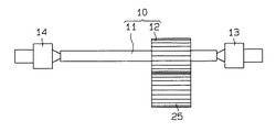
図6及び図7は、被測定部材としての歯車付きシャフトと、この歯車付きシャフトの歯車部における歯溝の振れを測定する従来の測定装置を示す。図6において、歯車付きシャフト10は、シャフト11と、該シャフト11を回転軸とした歯車部12を備えている。この歯車付きシャフト10の歯車部12における歯溝の振れに対する測定は、歯車付きシャフト10を図6で示すクランプ状態にし、図7で示す歯車測定装置20にて行うようになっている。図6に示すように、歯車付きシャフト10は、その両端がクランプ金具13,14にて挟持するようにクランプされている。また、クランプ金具13,14は図示しない回転駆動装置によって回転可能に支持されている。そして、回転駆動装置の回転に回転駆動されるクランプ金具13,14の回転によって歯車付きシャフト10は回転されるようになる。
【0004】
従来の歯車測定装置20は、図7に示すように、本体支柱21と、該本体支柱21一側面に設けられた回動軸22に回動可能に支持される梃子部材23とを備えている。梃子部材23は、その長さ方向の略中央位置に貫通孔23aを設けている。そして、その貫通孔23aに前記回動軸22が貫挿することによって梃子部材23は、前記本体支柱21に回動可能に支持される。このとき、前記回動軸22は梃子部材23の回動支点となっている。
【0005】
また、梃子部材23の一端(図7において左端)23bには、前記回動軸22の軸方向に平行する軸方向を有する回転軸24を設け、その回転軸24に前記歯車部12と同じ直径及び軸方向幅を有するマスタギア25を回転可能に支持している。
【0006】
前記本体支柱21の前記回動軸22の下方位置には、前記マスタギア25を設けた梃子部材23の一端側と反対する側(図7において右端)へ水平方向に延びる検出器支持部26が設けられている。該検出器支持部26は、前記梃子部材23の略1/2の長さにて形成されている。検出器支持部26の先端には、第1の検出器としての振れ検出器27が取り付けられている。
【0007】
振れ検出器27は、検出器本体27aと、該検出器本体27aにより収容保持される接触子27bと、接続ケーブル27cを介して該接触子27bと接続する測定コントローラ(図示せず)とから構成している。前記接触子27bは、前記検出器本体27a内に設けられた弾性部材(図示せず)によって同検出器本体27aの外方(図7において上方)へ伸出するように付勢されている。そして、この接触子27bは、前記弾性部材を抗する方向の押圧を受けたとき、検出器本体27a内に押入されるようになる。なお、前記検出器本体27aに対する接触子27bの伸縮可能の範囲は、予め所定範囲に定められている。そして、前記梃子部材23は図7に示すように水平に保持されるとき、その他端(図7において右端)23cの下面が前記接触子27bに当接し、接触子27bはその伸縮可能範囲の略中間位置にくるように梃子部材23により押圧される状態となっている。なお、梃子部材23はこのように水平状態に保持される位置を梃子部材23の基準位置としている。
【0008】
また、前記検出器支持部26は、その長さ方向中間位置に上方へ延びるストッパとしての凸部28が設けられている。凸部28は、その上面が前記梃子部材23の他端下面と所定距離を設けるように所定高さにて形成され、梃子部材23を所定値以上に傾かないように制限するものである。さらに、前記凸部28と前記振れ検出器27との間には、引張型スプリング29を検出器支持部26と前記梃子部材23とに掛着している。そして、前記梃子部材23は、その他端23cが常に検出器支持部26に近づこうとするよう前記スプリング29により付勢されている。
【0009】
一方、前記梃子部材23の一端23bに設けられたマスタギア25は、該マスタギア25の上方に位置し図7に示すように回転可能にクランプされた歯車付きシャフト10の歯車部12と噛合されている。そして、マスタギア25は、前記スプリング29の弾性力で常に前記歯車部12に付勢する状態で該歯車部12に噛合している。なお、歯車部12には歯溝の振れ及び後述するシャフト11の曲がり(歯車部12のカタギ)がない場合、前記梃子部材23が略水平状態となるようマスタギア25は前記歯車部12と噛合するように予め設定されている。つまり、歯車部12には歯溝の振れ及び後述するシャフト11の曲がり(歯車部12のカタギ)があった場合、歯車部12とともに回転するマスタギア25の上下動により前記梃子部材23が傾く。そして、回動軸22の軸中心からマスタギア25の軸中心までの距離と、回動軸22の軸中心から接触子27bの当接点までの距離を等しくしているため、前記検出器27にて歯車部12の歯溝の振れの測定値δが得られる。
【0010】
【発明が解決しようとする課題】
しかしながら、上記従来の歯車測定装置20は、歯車付きシャフト10のシャフト11に曲がり(歯車部12のカタギ)があった場合、シャフト11の曲がりに対する測定ができないとともに、歯車部12の歯溝の振れに対する測定を正確に行うことができないという問題点があった。
【0011】
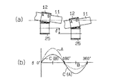
図8は、歯車部12の歯溝の振れ及びシャフト11の曲がり(歯車部12のカタギ)があり、しかも歯車部12の歯溝の振れとシャフト11の曲がり(歯車部12のカタギ)が同位相である場合の測定結果を示す説明図である。図9は、シャフト11の曲がり(歯車部12のカタギ)のみあった場合の測定結果を示す説明図である。
【0012】
詳述すると、図8(a)及び図9(a)に示すように、シャフト11の曲がり(歯車部12のカタギ)があるため、歯車部12がマスタギア25と全面あたりにならず隙間が発生している。つまり、歯車部12が一周(360°)に回転するとき、歯車部12がマスタギア25とのあたりは、図8(a)及び図9(a)に示すように、一端(右端)Bから他端(左端)Aへ移動するようになる。そして、歯車部12は一端Bでマスタギア25とあたるとき、他端Aとマスタギア25との間に隙間が生じ、他端Aでマスタギア25とあたるとき、一端Bとマスタギア25との間に隙間が生じる。振れ検出器27にて測定したマスタギア25の上下動幅(即ち、歯車部12の一端Bと他端Aでの歯溝の振れ)をグラフで表すと、図8(b)及び図9(b)に示すようになる。図8(b)及び図9(b)において、一端Bに対応するマスタギア25の上下動幅を破線で示し、他端Aに対応するマスタギア25の上下動幅を1点鎖線で示している。
【0013】
この場合、前半回転(0〜180°)においてマスタギア25は歯車部12の一端Bにあたり、後半回転(180°〜360°)においてマスタギア25は歯車部12の他端Aにあたるようになる。そのため、この状態で測定行うと、歯車部12の歯溝の振れは、前半回転(0〜180°)において歯車部12の一端Bに対応するマスタギア25の上下動幅(図において実線Cで示す)にて測定され、後半回転(180°〜360°)において歯車部12の他端Aに対応するマスタギア25の上下動幅(図において実線Cで示す)にて測定される。
【0014】
それにより、隙間がある部分における歯車部12の歯溝の振れが測定できないだけでなく、マスタギア25の上下動幅は実際の歯車部12の歯溝の振れより小さく測定される。しかも、シャフト11の曲がり(歯車部12のカタギ)の成分に対する測定ができないため、図8(b)の場合においてシャフト11の曲がり(歯車部12のカタギ)の成分にて歯車部12の歯溝の振れに対する補正(各成分による合成)はできなく、図9(b)の場合において、シャフト11の曲がり(歯車部12のカタギ)によるマスタギア25の上下動は歯車部12の歯溝の振れとして測定してしまう。
【0015】
その結果、従来の歯車測定装置20は、シャフト11の曲がりに対する測定ができないとともに、歯車部12の歯溝の振れに対する測定を正確に行うことができない。
【0016】
本発明の目的は、歯車付きシャフトのシャフトの曲がり(歯車部のカタギ)を測定できるとともに、歯車部の歯溝の振れに対する測定を正確に行うことができる歯車測定装置及び歯車測定方法を提供することにある。
【0017】
【課題を解決するための手段】
上記問題点を解決するために、請求項1に記載の発明は、マスタギアをシャフトに歯車部が一体に設けられた被測定部材の歯車部に噛合させ、前記被測定部材の回転により歯車部とともに回転されるマスタギアの上下動を測定することにより前記歯車部の歯溝の振れを測定する歯車測定装置において、前記マスタギアを、その軸線を中心軸として回転可能に支持するギア支持部材と、前記ギア支持部材を回動可能に支持するとともに、前記マスタギアの上下動を追随する方向に回動可能に設けられた回動部材と、前記マスタギアの上下動方向における前記回動部材の変位量を検出する第1の検出器とを備え、前記ギア支持部材は、その回動軸が前記マスタギアの軸線に対して直交する方向に延びるように前記回動部材に回動可能に支持され、前記シャフトの曲がりによる歯車部のカタギに追随するように前記ギア支持部材が回動して、前記マスタギアの軸線と前記歯車部の軸線とが平行になることを要旨とする。
【0018】
請求項2に記載の発明は、マスタギアをシャフトに歯車部が一体に設けられた被測定部材の歯車部に噛合させ、前記被測定部材の回転により歯車部とともに回転されるマスタギアの上下動を測定することにより前記歯車部の歯溝の振れを測定する歯車測定装置において、前記マスタギアを、その軸線を中心軸として回転可能に支持するギア支持部材と、前記ギア支持部材を回動可能に支持する回動部材と、前記回動部材に設けられ、当該回動部材に対する前記歯車部のカタギ方向における前記ギア支持部材の変位量を測定する第2の検出器とを備え、前記ギア支持部材は、その回動軸が前記マスタギアの軸線に対して直交する方向に延びるように前記回動部材に回動可能に支持され、前記シャフトの曲がりによる歯車部のカタギに追随するように前記ギア支持部材が回動して、前記マスタギアの軸線と前記歯車部の軸線とが平行になるたことを要旨とする。
【0019】
請求項3に記載の発明は、請求項2に記載の歯車測定装置において、前記回動部材は、マスタギアの上下動を追随する方向に回動可能に設けられ、前記マスタギアの上下動方向における該回動部材の変位量を検出する第1の検出器を設けたことを要旨とする。
【0020】
請求項4に記載の発明は、請求項2又は3に記載の歯車測定装置において、検出した前記ギア支持部材の変位量と、検出した前記回動部材の変位量に基づいて前記歯車部の歯溝の振れを推定する推定手段を備えたことを要旨とする。
請求項5に記載の発明は、請求項1〜4のいずれか一項に記載の歯車測定装置において、前記回動部材と前記ギア支持部材とはスプリングによって連結され、前記ギア支持部材は、前記回動部材に対して所定の基準位置となるように前記スプリングにより付勢されていることを要旨とする。
【0021】
請求項6に記載の発明は、請求項1〜5のいずれか一項に記載の歯車測定装置にて前記被測定部材の歯車部の歯溝の振れを測定する歯車測定方法であって、前記ギア支持部材の変位量と、前記回動部材の変位量をそれぞれ検出し、前記ギア支持部材の変位量と前記回動部材の変位量に基づいて前記歯車部の歯溝の振れの測定値を推定するようにしたことを要旨とする。
【0022】
(作用)
請求項1に記載の発明の構成によれば、ギア支持部材が歯車部のカタギ方向を追随して回動することによってマスタギアは全面的に被測定部材の歯車部と当たることができる。この状態から、マスタギアの上下動による回動部材の変位量を測定するため、従来に比べて、マスタギアと歯車部間の隙間の発生による測定値のバラツキを防止でき、歯溝の振れに対する測定をより正確に行うことができる。
【0023】
請求項2に記載の発明の構成によれば、マスタギアが全面的に被測定部材の歯車部と当たる状態でマスタギアの上下動を測定することによって歯溝の振れを正確に測定することができるとともに、歯車部のカタギ方向におけるギア支持部材の変位量を測定することができる。つまり、歯車部の歯溝の振れと歯車部のカタギを区分して測定できるため、得られた歯車部のカタギの測定値成分にて歯溝の振れの測定値を補正することができる。その結果、従来に比べ、歯溝の振れに対する測定を正確に行うことができる。
【0024】
請求項3に記載の発明の構成によれば、請求項2の発明の作用に加えて、歯車部のカタギ方向におけるギア支持部材の変位量とマスタギアの上下動方向における回動部材の変位量を同時に測定することができる。その結果、被測定部材の歯車部のカタギ及び歯車部の歯溝の振れに対する測定の時間を短縮することができるとともに、歯車部のカタギ方向におけるギア支持部材の変位量とマスタギアの上下動方向における回動部材の変位量を別々測定する場合に比べて歯溝の振れに対する測定精度の向上を図ることができる。
【0025】
また、1つのマスタギアにて歯車部の歯溝の振れと歯車部のカタギを測定することができ、2つのマスタギアにてそれらを別々測定する場合に比べ、歯車測定装置の部品点数の低減を図るでき、コスト的に優れている。
【0026】
さらに、マスタギアの軸方向幅を被測定部材の歯車部の軸方向幅と同じとなるようにすることができ、マスタギアの軸方向幅が被測定部材の歯車部の軸方向幅と異なる場合に比べ、歯車部の歯溝の振れに対する測定精度を更に向上することができる。
【0027】
請求項4に記載の発明の構成によれば、請求項2及び3の発明の作用に加えて、それぞれ検出したギア支持部材の変位量と回動部材の変位量に基づいて歯車部の歯溝の振れの測定値を推定するようにした。従って、歯車部の各部分の歯溝の振れを正確に把握でき、被測定部材に対する歪矯正の押し込みストロークを正確に設定できる。
請求項5に記載の発明の構成によれば、請求項1〜4のいずれか一項の発明の作用に加えて、ギア支持部材を所定の基準位置に付勢することができる。
請求項6に記載の発明の構成によれば、歯車部の各部分の歯溝の振れを正確に把握できる。
【0028】
【発明の実施の形態】
以下、本発明を歯車付きシャフトの歯車測定装置に具体化した一実施形態を図面に従って説明する。なお、本実施形態の歯車測定装置は、その歯車部の歯溝の振れを測定する振れ測定部が従来の歯車測定装置20の構造とはほぼ同じであるため、説明の便宜上、同じ部分に対して同じ符号を付し詳細な説明を省略し、異なる部分について詳しく説明する。
【0029】
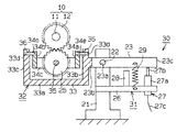
図1に示すように、本実施形態の歯車測定装置30は、振れ測定部31とカタギ測定部32を備えている。振れ測定部31は、本体支柱21と、該本体支柱21に設けられた回動軸22に対して回動可能に支持される梃子部材23とを有している。
【0030】
図1〜図3に示すように、前記カタギ測定部32は、ブラケット33とギア支持部材としてのホルダー34とを備えている。ブラケット33は、平板部33aと、該平板部33a上に立設された2つの支柱部33b,33cとから構成されている。一方の支柱部33bは、振れ測定部31を構成する梃子部材23の一端23bと一体に形成されている。また、両支柱部33b,33cの上端部には、それぞれ貫通孔33dを設けている。
【0031】
前記ホルダー34は、互いに平行する2つの梃子板34a,34bと、その両梃子板34a,34bと直交するように当該両梃子板34a,34bを連結する2つのギア支持板34c,34dとから構成されている。両梃子板34a,34bには、それぞれ貫通孔34eを設け、両ギア支持板34c,34dには、それぞれ貫通孔34fを設けている。
【0032】
そして、両梃子板34a,34bと両ギア支持板34c,34dにより囲まれた空間には、マスタギア25は、その回動軸35が前記両貫通孔34fを貫挿するようにギア支持板34c,34dにより回転可能に支持されている。また、マスタギア25を取り付けたホルダー34は、前記両貫通孔34eを貫挿固定した両回動軸36が前記両貫通孔33dを貫挿するように回動可能にブラケット33に支持されている。この構成により、ホルダー34は、ブラケット33に対して傾け可能に支持されている。
【0033】
また、前記ブラケット33の平板部33aには、第2の検出器としてのカタギ検出器37を設けている。本実施形態では、図2及び図3に示すように、カタギ検出器37は、前記梃子板34bの一端(右端)下方に位置するように設けられている。
【0034】
カタギ検出器37は、平板部33aに固定された検出器本体37aと、該検出器本体37aにより収容保持される接触子37bと、接続ケーブル37cを介して該接触子37bと接続する測定コントローラ(図示せず)とから構成している。なお、この接触子37bに接続する測定コントローラは前記接触子27bに接続する測定コントローラと同一のものにしてもよい。
【0035】
前記接触子37bは、前記検出器本体37a内に設けられた弾性部材(図示せず)によって同検出器本体37aの外方(図2において上方)へ伸出するように付勢されている。そして、この接触子37bは、前記弾性部材を抗する方向の押圧を受けたとき、検出器本体37a内に押入されるようになる。そして、前記梃子板34bは図2に示すように水平に保持されるとき、その一端(右端)下面が前記接触子37bに当接し、このとき接触子37bはその伸縮可能範囲の略中間位置にくるように梃子板34bにより押圧される状態となる。なお、梃子板34bはこのように水平状態に保持される位置を梃子板34b(つまりホルダー34)の基準位置としている。
【0036】
また、前記支柱部33bとカタギ検出器37との間には、一端が平板部33aに固着し、他端が梃子板34bに固着する引張型スプリング38を設けている。支柱部33bに対してこの引張型スプリング38とほぼ対称となる位置には、前記梃子板34bの他端(左端)と平板部33aを連結する引張型スプリング39を設けている。本実施形態では、ホルダー34が外力により傾かない限りに梃子板34bは常に平板部33aと平行するよう両スプリング38,39により水平状態に保持されるようになる。
【0037】
さらに、図2に示すように、前記スプリング38と支柱部33bの間、前記スプリング39と支柱部33bの間には、それぞれストッパとしての凸部40を設けている。凸部40は、その上面が前記梃子板34bの両端下面と所定距離を設けるように所定高さにて形成され、梃子板34bを所定値以上に傾かないように制限するものである。
【0038】
次に、本実施形態の歯車測定装置30にて歯車付きシャフト10の歯車部12を測定する方法について説明する。
まず、図1に示すように、ホルダー34及びブラケット33を介して前記梃子部材23の一端23bに設けられたマスタギア25を、該マスタギア25の上方に位置し回転可能にクランプされた(図6参照)歯車付きシャフト10の歯車部12と噛合させる。そして、マスタギア25は、前記スプリング29の弾性力で常に前記歯車部12に付勢する状態で該歯車部12に噛合する。なお、本実施形態では、歯車部12には歯溝の振れがない場合、前記梃子部材23が水平状態(つまり基準位置)となるようマスタギア25は前記歯車部12と噛合するように予め設定されている。
【0039】
そして、測定すべく歯車付きシャフト10の歯車部12を前記マスタギア25と噛合した状態で歯車付きシャフト10を回転させる。このとき、もし歯車付きシャフト10のシャフト11は曲がり(歯車部12のカタギ)がなかったら、マスタギア25は傾くことなく歯車部12に全面的に当たる状態で該歯車部12とともに回転される。このとき、歯車部12の歯溝の振れがあっても、カタギ検出器37によるシャフト11の曲がり(歯車部12のカタギ)の測定値tがゼロとなり、振れ検出器27から検出されたマスタギア25の上下動幅により歯車部12の歯溝の振れの測定値δを換算できる。
【0040】
図4及び図5は、歯車付きシャフト10のシャフト11は曲がり(歯車部12のカタギ)があった場合における歯車測定装置30の測定を示す説明図である。図4(a)及び図5(a)に示すように、歯車付きシャフト10のシャフト11は曲がりが(歯車部12のカタギ)あった場合、ブラケット33(つまり梃子部材23)に対してホルダー34が傾くことができるため、マスタギア25は傾きながら歯車部12に全面的に当たる状態で該歯車部12とともに回転される。そして、歯車付きシャフト10を一周(360°)回転したとき、マスタギア25の傾きの変化(変位量)をカタギ検出器37により検出し、その傾きの変化(変位量)を測定コントローラにて前記シャフト11の曲がり(歯車部12のカタギ)の測定値tに換算できる。その測定値tを図4(b)及び図5(b)に実線Dで示している。一方、このとき、マスタギア25は歯車部12に全面的に当たる状態で該歯車部12とともに回転されるため、振れ検出器27により検出されたブラケット33(つまりマスタギア25)の上下動幅の変化が測定コントローラにより歯車部12における歯溝の振れの平均測定値δに換算される。その平均測定値δは、図4(b)及び図5(b)に示している(図において実線Cで示す)。図5(b)において、その平均測定値δはゼロとなり(図において実線Cで示す)、この場合、歯車付きシャフト10には、歯車部12の歯溝の振れがないと判定できる。
【0041】
また、本実施形態では、前記測定値t、平均測定値δ及び歯車部12の軸線方向幅に基づいて推定手段としての測定コントローラは所定合成演算式にて歯車部12の軸線方向両端A,B部分の歯溝の振れを推定している。これらの推定値に基づいて歯車付きシャフト10に対する歪矯正の押し込みストロークを設定する。
【0042】
以上詳述したように、本実施形態によれば、以下に示す効果が得られる。
(1)本実施形態では、歯車測定装置30は、振れ測定部31とカタギ測定部32を備え、振れ測定部31にて歯車部12の歯溝の振れを測定し、カタギ測定部32にてシャフト11の曲がり(歯車部12のカタギ)を測定するようにした。
【0043】
従って、歯車部12のカタギを測定することができるとともに、歯車部12の歯溝の振れと歯車部12のカタギを区分して測定したため、得られた歯車部12のカタギの測定値成分にて歯車部12の歯溝の振れの測定値を補正することができ、歯溝の振れに対する測定を正確に行うことができる。
【0044】
(2)本実施形態では、ホルダー34は、マスタギア25を回転可能に支持するとともに、シャフト11の曲がりによる歯車部12のカタギ方向を追随するように回動可能にブラケット33に支持されている。
【0045】
従って、マスタギア25は歯車部12のカタギ方向を追随して同歯車部12に全面的に当たる状態で当該歯車部12とともに回転することができる。つまり、マスタギア25が常に歯車部12に全面的に当たる状態で歯車部12の歯溝の振れを測定できる。その結果、従来技術に比べて、マスタギア25と歯車部12間の隙間の発生による測定値のバラツキを防止でき、歯溝の振れに対する測定をより正確に行うことができる。
【0046】
(3)本実施形態では、ブラケット33は、梃子部材23の一端23bに一体に形成されている。つまり、歯車部12のカタギ方向におけるホルダー34の変位量tをカタギ検出器37にて測定すると同時に、マスタギア25の上下動方向におけるブラケット33(梃子部材23)の変位量δを検出器27にて測定できる。従って、歯車付きシャフト10の歯車部12のカタギ及び歯車部12の歯溝の振れに対する測定の時間を短縮することができるとともに、歯車部12のカタギ方向におけるホルダー34の変位量tとマスタギア25の上下動方向におけるブラケット33(マスタギア25)の変位量δを別々測定する場合に比べて歯車部12の歯溝の振れに対する測定精度の向上を図ることができる。
【0047】
また、1つのマスタギア25にて歯車部12の歯溝の振れと歯車部12のカタギを測定することができ、2つのマスタギアにてそれらを別々測定する場合に比べ、歯車測定装置30の部品点数の低減を図るでき、コスト的に優れている。
【0048】
さらに、マスタギア25の軸方向幅を歯車付きシャフト10の歯車部12の軸方向幅と同じとなるようにすることができ、それらが異なる(特にマスタギアの軸方向幅が歯車付きシャフト10の歯車部12の軸方向幅より小さい)場合に比べ、歯車部12の歯溝の振れに対する測定精度を向上することができる。
【0049】
(4)本実施形態では、歯車部12のカタギ測定値t、歯車部12の歯溝の振れの平均測定値δに基づいて測定コントローラは歯車部12の軸線方向両端A,B部分の歯溝の振れを推定することができる。
【0050】
その結果、歯車部12の各部分の歯溝の振れを正確に把握でき、歯車付きシャフト10に対する歪矯正の押し込みストロークを正確に設定できる。
なお、本発明の実施の形態は上記実施形態に限定されるものではなく、次のように変更してもよい。
【0051】
・マスタギア25を歯車部12と異なる直径にて実施してもよい。
・上記実施形態では、ブラケット33と梃子部材23は一体に形成されたが、ブラケット33を梃子部材23の一端23bに取付固定するように実施してもよい。
【0052】
・歯車付きシャフト10は、シャフト11に歯車部12を取付固定するように形成されてもよい。
・スプリング29,38,39の替わりに、弾性ゴム等のその他の弾性部材にて実施してもよい。
【0053】
・カタギ検出器37を、梃子板34bの他端(図2及び図3において左端)下方に位置するように設けてもよい。
・上記実施形態では、マスタギア25を取り付けたホルダー34は、両貫通孔34eを貫挿固定した両回動軸36が両貫通孔33dを貫挿するように回動可能にブラケット33に支持されている。マスタギア25を取り付けたホルダー34を、両貫通孔34eを貫挿した両回動軸36が両貫通孔33dを貫挿固定するように回動可能にブラケット33に支持してもよい。
【0054】
・歯車測定装置30は、カタギ検出器37を省略してマスタギア25の上下動のみ測定するものにして実施してもよい。この場合、従来技術に比べて、マスタギア25と歯車部12間の隙間の発生による測定値のバラツキを防止でき、歯車部12の歯溝の振れに対する測定をより正確に行うことができる。
【0055】
・歯車測定装置30は、振れ検出器27を省略して歯車部12のカタギを追随するホルダー34の変位量のみ測定するものにして実施してもよい。
次に、以上の実施形態及び別例から把握することができる請求項以外の技術的思想を、その効果とともに以下に記載する。
【0056】
(1)シャフト(11)に歯車部(12)が一体に設けられた被測定部材(10)の歯車部(12)に噛合するマスタギア(25)を回転可能に支持するギア支持部材(34)と、前記ギア支持部材(34)を前記シャフト(11)の曲がりによる歯車部(12)のカタギを追随するように回動可能に支持する回動部材(33)と、前記回動部材(33)に設け前記歯車部(12)のカタギ方向における前記ギア支持部材(34)の変位量(t)を測定する第2の検出器(37)とを備えたことを特徴とする歯車測定装置。
【0057】
この構成によれば、歯車部のカタギを単独に測定することができる。
【0058】
【発明の効果】
以上詳述したように、請求項1に記載の発明の構成によれば、従来に比べて、マスタギアと歯車部間の隙間の発生による測定値のバラツキを防止でき、歯溝の振れに対する測定をより正確に行うことができる。
【0059】
請求項2に記載の発明の構成によれば、歯車部のカタギを測定することができるとともに歯車部の歯溝の振れと歯車部のカタギを区分して測定できる。その結果、従来に比べ、歯溝の振れに対する測定を更に正確に行うことができる。
【0060】
請求項3に記載の発明の構成によれば、請求項2の発明の効果に加えて、被測定部材の歯車部のカタギ及び歯車部の歯溝の振れに対する測定の時間を短縮することができるとともに、歯溝の振れに対する測定精度の向上を図ることができる。
【0061】
請求項4に記載の発明の構成によれば、請求項2及び3の発明の効果に加えて、歯車部の各部分の歯溝の振れを正確に把握でき、被測定部材に対する歪矯正の押し込みストロークを正確に設定できる。
請求項5に記載の発明の構成によれば、請求項1〜4のいずれか一項の発明の作用に加えて、ギア支持部材を所定の基準位置に付勢することができる。
請求項6に記載の発明の構成によれば、歯車部の各部分の歯溝の振れを正確に把握できる。
【図面の簡単な説明】
【図1】本実施形態の歯車測定装置の要部正面図。
【図2】同じく歯車測定装置の要部側面図。
【図3】同じく歯車測定装置の要部平面図。
【図4】同じく歯車測定装置による測定方法及び測定結果を示す説明図。
【図5】同じく歯車測定装置による測定方法及び測定結果を示す説明図。
【図6】歯車付きシャフトをクランプする状態を示す正面図。
【図7】従来の歯車測定装置の要部正面図。
【図8】従来の歯車測定装置による測定方法及び測定結果を示す説明図。
【図9】従来の歯車測定装置による測定方法及び測定結果を示す説明図。
【符号の説明】
10…被測定部材としての歯車付きシャフト、11…シャフト、12…歯車部、25…マスタギア、27…第1の検出器としての振れ検出器、33…回動部材としてのブラケット、34…ギア支持部材としてのホルダ、37…第2の検出器としてのカタギ検出器。[0001]
BACKGROUND OF THE INVENTION
The present invention relates to a gear measurement device, and more particularly, to a gear measurement device and a gear measurement method that can separately measure a tooth groove runout and a gear crack in a gear portion of a geared shaft.
[0002]
[Prior art]
Generally, in the manufacture of a geared shaft, after the gear and the shaft are integrally formed by forging, machining and heat treatment are performed on the formed coarse material of the geared shaft. At this time, when the geared shaft is subjected to heat treatment such as quenching, the geared shaft is distorted due to shaft distortion and gear portion distortion. In order to solve this problem, the gear shaft is usually subjected to distortion correction as post-processing of machining and heat treatment. And in order to know the amount of distortion correction of the shaft with gear, it is necessary to measure the runout of the tooth gap of the gear portion. In other words, the distortion correction amount of the geared shaft is determined based on the data obtained by measuring the tooth groove runout in the gear portion of the geared shaft.
[0003]
6 and 7 show a conventional measuring apparatus for measuring a geared shaft as a member to be measured and a tooth groove runout in a gear portion of the geared shaft. In FIG. 6, the geared
[0004]
As shown in FIG. 7, the conventional
[0005]
Further, a
[0006]
A
[0007]
The
[0008]
The
[0009]
On the other hand, a
[0010]
[Problems to be solved by the invention]
However, the above conventional
[0011]
In FIG. 8, there is a tooth groove deflection of the
[0012]
More specifically, as shown in FIG. 8A and FIG. 9A, the
[0013]
In this case, the
[0014]
Thereby, not only the tooth groove runout of the
[0015]
As a result, the conventional
[0016]
An object of the present invention is to provide a gear measuring device and a gear measuring method capable of measuring the bending of the shaft of the geared shaft (gear of the gear part) and accurately measuring the gear groove runout. There is.
[0017]
[Means for Solving the Problems]
In order to solve the above problems, the invention according to claim 1 is configured such that a master gear is engaged with a gear portion of a member to be measured in which a gear portion is integrally provided on a shaft, and together with the gear portion by rotation of the member to be measured. In a gear measuring device that measures the run-out of the tooth gap of the gear unit by measuring the vertical movement of the rotated master gear, the master gear is, With that axis as the central axisA gear support member rotatably supported, and the gear support memberTimesSupport movablyWithA rotation member provided to be rotatable in a direction to follow the vertical movement of the master gear; and a first detector for detecting a displacement amount of the rotation member in the vertical movement direction of the master gear.The gear support member is rotatably supported by the rotation member so that the rotation axis thereof extends in a direction perpendicular to the axis of the master gear, and follows the shape of the gear portion due to the bending of the shaft. As described above, the gear support member rotates so that the axis of the master gear and the axis of the gear portion become parallel to each other.This is the gist.
[0018]
According to the second aspect of the present invention, the master gear is engaged with the gear portion of the member to be measured in which the gear portion is integrally provided on the shaft, and the vertical movement of the master gear rotated together with the gear portion by the rotation of the member to be measured is measured. In the gear measuring device that measures the runout of the tooth gap of the gear portion, the master gear is, With that axis as the central axisA gear support member rotatably supported, and the gear support memberTimesRotating member that is movably supported and provided on the rotating memberAgainst the rotating memberA second detector that measures the amount of displacement of the gear support member in the direction of the gear portion.The gear support member is rotatably supported by the rotation member so that the rotation axis thereof extends in a direction perpendicular to the axis of the master gear, and follows the shape of the gear portion due to the bending of the shaft. As described above, the gear support member rotates so that the axis of the master gear and the axis of the gear portion become parallel to each other.This is the summary.
[0019]
According to a third aspect of the present invention, in the gear measurement device according to the second aspect, the rotating member is provided so as to be rotatable in a direction to follow the vertical movement of the master gear, and the master gear in the vertical movement direction. The gist is that a first detector for detecting the amount of displacement of the rotating member is provided.
[0020]
According to a fourth aspect of the present invention, there is provided the gear measuring device according to the second or third aspect, wherein the gear portion tooth is based on the detected displacement amount of the gear support member and the detected displacement amount of the rotating member. The gist is that an estimation means for estimating the runout of the groove is provided.
Invention of Claim 5 is a gear measuring apparatus as described in any one of Claims 1-4. WHEREIN: The said rotation member and the said gear support member are connected with the spring, The said gear support member is the said gear support member. The gist is that the rotating member is biased by the spring so as to be a predetermined reference position.
[0021]
Claim 6The invention described inAny one of Claims 1-5A gear measurement method for measuring a runout of a tooth groove of a gear portion of the member to be measured using the gear measurement device according to claim 1, wherein a displacement amount of the gear support member and a displacement amount of the rotating member are detected. The gist of the present invention is to estimate the measured value of the tooth groove runout of the gear portion based on the displacement amount of the gear support member and the displacement amount of the rotating member.
[0022]
(Function)
According to the configuration of the first aspect of the present invention, the master gear can come into full contact with the gear portion of the member to be measured as the gear support member rotates following the click direction of the gear portion. Since the amount of displacement of the rotating member due to the vertical movement of the master gear is measured from this state, it is possible to prevent variation in the measured value due to the generation of a gap between the master gear and the gear portion, and to measure the tooth gap run-out. It can be done more accurately.
[0023]
According to the configuration of the second aspect of the present invention, it is possible to accurately measure the runout of the tooth gap by measuring the vertical movement of the master gear in a state where the master gear entirely contacts the gear portion of the member to be measured. The amount of displacement of the gear support member in the direction of the gear portion can be measured. That is, since the tooth gap runout of the gear portion and the gear settling can be measured separately, the measured value of the tooth gap runout can be corrected by the measured component component of the gear set obtained. As a result, it is possible to accurately measure the tooth gap runout as compared with the prior art.
[0024]
According to the configuration of the invention described in claim 3, in addition to the action of the invention of claim 2, the amount of displacement of the gear support member in the direction of the gear portion and the amount of displacement of the rotating member in the vertical movement direction of the master gear are determined. It can be measured simultaneously. As a result, it is possible to reduce the measurement time with respect to the gear portion of the member to be measured and the gear groove tooth runout, and the displacement of the gear support member in the direction of the gear portion and the vertical movement direction of the master gear. Compared with the case where the amount of displacement of the rotating member is measured separately, it is possible to improve the measurement accuracy with respect to tooth gap runout.
[0025]
In addition, the tooth gap run-out of the gear part and the gear part of the gear part can be measured with one master gear, and the number of parts of the gear measuring device can be reduced as compared with the case of separately measuring them with two master gears. And cost is excellent.
[0026]
Furthermore, the axial width of the master gear can be made the same as the axial width of the gear portion of the member to be measured, compared with the case where the axial width of the master gear is different from the axial width of the gear portion of the member to be measured. Moreover, the measurement accuracy with respect to the runout of the tooth gap of the gear portion can be further improved.
[0027]
Claim 4According to the configuration of the invention described in (2), in addition to the effects of the inventions of the second and third aspects, based on the detected displacement amount of the gear support member and the displacement amount of the rotating member, the tooth groove deviation of the gear portion is detected. The measured value was estimated. Accordingly, it is possible to accurately grasp the vibration of the tooth gap of each part of the gear portion, and it is possible to accurately set the distortion correction pushing stroke with respect to the member to be measured.
According to the configuration of the invention described in claim 5, in addition to the operation of the invention of any one of claims 1 to 4, the gear support member can be biased to a predetermined reference position.
According to the configuration of the invention described in claim 6, it is possible to accurately grasp the runout of the tooth groove of each part of the gear portion.
[0028]
DETAILED DESCRIPTION OF THE INVENTION
Hereinafter, an embodiment in which the present invention is embodied in a gear measuring device for a geared shaft will be described with reference to the drawings. In the gear measurement device of the present embodiment, the runout measurement unit that measures the runout of the tooth gap of the gear unit is substantially the same as the structure of the conventional
[0029]
As shown in FIG. 1, the
[0030]
As shown in FIGS. 1 to 3, the
[0031]
The
[0032]
In the space surrounded by the two
[0033]
Further, the
[0034]
The
[0035]
The
[0036]
Further, a
[0037]
Further, as shown in FIG. 2,
[0038]
Next, a method for measuring the
First, as shown in FIG. 1, a
[0039]
Then, the geared
[0040]
4 and 5 are explanatory views showing measurement of the
[0041]
Further, in the present embodiment, the measurement controller as the estimation means based on the measurement value t, the average measurement value δ, and the axial width of the
[0042]
As described above in detail, according to the present embodiment, the following effects can be obtained.
(1) In the present embodiment, the
[0043]
Therefore, the gear of the
[0044]
(2) In the present embodiment, the
[0045]
Accordingly, the
[0046]
(3) In the present embodiment, the
[0047]
Further, the tooth groove run-out of the
[0048]
Further, the axial width of the
[0049]
(4) In this embodiment, based on the measured value t of the
[0050]
As a result, it is possible to accurately grasp the vibration of the tooth groove of each part of the
In addition, embodiment of this invention is not limited to the said embodiment, You may change as follows.
[0051]
The
In the above embodiment, the
[0052]
The geared
-Instead of the
[0053]
-You may provide the
In the above-described embodiment, the
[0054]
The
[0055]
The
Next, technical ideas other than the claims that can be understood from the above embodiment and other examples will be described below together with the effects thereof.
[0056]
(1) A gear support member (34) that rotatably supports a master gear (25) that meshes with a gear portion (12) of a member to be measured (10) in which a gear portion (12) is integrally provided on a shaft (11). A rotation member (33) that rotatably supports the gear support member (34) so as to follow the shape of the gear portion (12) caused by the bending of the shaft (11), and the rotation member (33). And a second detector (37) for measuring a displacement (t) of the gear support member (34) in the direction of the gear portion (12).
[0057]
According to this configuration, the gear of the gear portion can be measured independently.
[0058]
【The invention's effect】
As described above in detail, according to the configuration of the invention described in claim 1, it is possible to prevent variation in measurement values due to the generation of a gap between the master gear and the gear portion, and to measure the tooth gap run-out. It can be done more accurately.
[0059]
According to the configuration of the invention described in claim 2, it is possible to measure the shift of the gear part, and to measure separately the runout of the tooth gap of the gear part and the shift of the gear part. As a result, it is possible to more accurately measure the tooth gap run-out than in the past.
[0060]
According to the configuration of the invention described in claim 3, in addition to the effect of the invention of claim 2, it is possible to reduce the measurement time for the gear portion of the member to be measured and the gear portion tooth groove runout. At the same time, it is possible to improve the measurement accuracy with respect to tooth gap run-out.
[0061]
Claim 4In addition to the effects of the inventions of claims 2 and 3, the configuration of the invention described in (2) can accurately grasp the vibration of the tooth gap of each part of the gear portion, and the distortion correction pushing stroke to the member to be measured can be accurately determined. Can be set.
According to the configuration of the invention described in claim 5, in addition to the operation of the invention of any one of claims 1 to 4, the gear support member can be biased to a predetermined reference position.
According to the configuration of the invention described in claim 6, it is possible to accurately grasp the runout of the tooth groove of each part of the gear portion.
[Brief description of the drawings]
FIG. 1 is a front view of a main part of a gear measuring device according to an embodiment.
FIG. 2 is a side view of an essential part of the gear measuring device.
FIG. 3 is a plan view of an essential part of the gear measuring device.
FIG. 4 is an explanatory view showing a measurement method and a measurement result by the gear measurement device.
FIG. 5 is an explanatory view showing a measurement method and a measurement result by the gear measurement device.
FIG. 6 is a front view showing a state in which a geared shaft is clamped.
FIG. 7 is a front view of a main part of a conventional gear measuring device.
FIG. 8 is an explanatory view showing a measuring method and a measurement result by a conventional gear measuring device.
FIG. 9 is an explanatory view showing a measurement method and a measurement result by a conventional gear measurement device.
[Explanation of symbols]
DESCRIPTION OF
Claims (6)
前記マスタギア(25)を、その軸線を中心軸として回転可能に支持するギア支持部材(34)と、
前記ギア支持部材(34)を回動可能に支持するとともに、前記マスタギア(25)の上下動を追随する方向に回動可能に設けられた回動部材(33)と、
前記マスタギア(25)の上下動方向における前記回動部材(33)の変位量(δ)を検出する第1の検出器(27)とを備え、
前記ギア支持部材(34)は、その回動軸(36)が前記マスタギア(25)の軸線に対して直交する方向に延びるように前記回動部材(33)に回動可能に支持され、
前記シャフト(11)の曲がりによる歯車部(12)のカタギに追随するように前記ギア支持部材(34)が回動して、前記マスタギアの軸線(25)と前記歯車部(12)の軸線とが平行になることを特徴とする歯車測定装置。The master gear (25) is engaged with the gear portion (12) of the member to be measured (10) in which the gear portion (12) is integrally provided on the shaft (11), and the gear portion ( 12) In the gear measuring device that measures the vertical movement of the gear portion (12) by measuring the vertical movement of the master gear (25) rotated together with the gear gear,
A gear support member (34) for rotatably supporting the master gear (25) about the axis thereof as a central axis ;
While supporting the gear support member (34) turnably, and rotating member provided to be rotatable in a direction to follow the vertical movement of the Masutagia (25) (33),
A first detector (27) for detecting a displacement amount (δ) of the rotating member (33) in the vertical movement direction of the master gear (25) ,
The gear support member (34) is rotatably supported by the rotation member (33) such that the rotation shaft (36) extends in a direction orthogonal to the axis of the master gear (25),
The gear support member (34) rotates so as to follow the shape of the gear portion (12) due to the bending of the shaft (11), and the axis line (25) of the master gear and the axis line of the gear portion (12) Gear measuring device characterized in that the two are parallel .
前記マスタギア(25)を、その軸線を中心軸として回転可能に支持するギア支持部材(34)と、
前記ギア支持部材(34)を回動可能に支持する回動部材(33)と、
前記回動部材(33)に設けられ、当該回動部材(33)に対する前記ギア支持部材(34)の変位量(t)を測定する第2の検出器(37)とを備え、
前記ギア支持部材(34)は、その回動軸(36)が前記マスタギア(25)の軸線に対して直交する方向に延びるように前記回動部材(33)に回動可能に支持され、
前記シャフト(11)の曲がりによる歯車部(12)のカタギに追随するように前記ギア支持部材(34)が回動して、前記マスタギアの軸線(25)と前記歯車部(12)の軸線とが平行になることを特徴とする歯車測定装置。The master gear (25) is engaged with the gear portion (12) of the member to be measured (10) in which the gear portion (12) is integrally provided on the shaft (11), and the gear portion ( 12) In the gear measuring device that measures the vertical movement of the gear portion (12) by measuring the vertical movement of the master gear (25) rotated together with the gear gear,
A gear support member (34) for rotatably supporting the master gear (25) about the axis thereof as a central axis ;
The gear support member (34) for turnably supporting pivot member (33),
A second detector (37) provided on the rotating member (33) for measuring a displacement amount (t) of the gear support member (34) relative to the rotating member (33) ;
The gear support member (34) is rotatably supported by the rotation member (33) such that the rotation shaft (36) extends in a direction orthogonal to the axis of the master gear (25),
The gear support member (34) rotates so as to follow the shape of the gear portion (12) due to the bending of the shaft (11), and the axis line (25) of the master gear and the axis line of the gear portion (12) Gear measuring device characterized in that the two are parallel .
前記回動部材(33)は、マスタギア(25)の上下動を追随する方向に回動可能に設けられ、前記マスタギア(25)の上下動方向における該回動部材(33)の変位量(δ)を検出する第1の検出器(27)を設けたことを特徴とする歯車測定装置。In the gear measuring device according to claim 2,
The rotating member (33) is provided so as to be rotatable in a direction to follow the vertical movement of the master gear (25), and the displacement amount (δ) of the rotating member (33) in the vertical movement direction of the master gear (25). A gear measuring device provided with a first detector (27) for detecting).
検出した前記ギア支持部材(34)の変位量(t)と、検出した前記回動部材(33)の変位量(δ)に基づいて前記歯車部(12)の歯溝の振れを推定する推定手段を備えたことを特徴とする歯車測定装置。In the gear measuring device according to claim 2 or 3,
Estimation that estimates the tooth groove runout of the gear portion (12) based on the detected displacement amount (t) of the gear support member (34) and the detected displacement amount (δ) of the rotating member (33). A gear measuring device comprising means.
前記回動部材(33)と前記ギア支持部材(34)とはスプリング(38、39)によって連結され、前記ギア支持部材(34)は、前記回動部材(33)に対して所定の基準位置となるように前記スプリングにより付勢されていることを特徴とする歯車測定装置。 The rotating member (33) and the gear support member (34) are connected by springs (38, 39), and the gear support member (34) is a predetermined reference position with respect to the rotating member (33). The gear measuring device is biased by the spring so that
前記ギア支持部材(34)の変位量(t)と、前記回動部材(33)の変位量(δ)をそれぞれ検出し、前記ギア支持部材(34)の変位量(t)と前記回動部材(33)の変位量(δ)に基づいて前記歯車部(12)の歯溝の振れの測定値を推定するようにしたことを特徴とする歯車測定方法。A gear measurement method for measuring runout of a tooth groove of a gear part (12) of the member to be measured (10) by the gear measurement device according to any one of claims 1 to 5 ,
The displacement amount (t) of the gear support member (34) and the displacement amount (δ) of the rotation member (33) are detected, respectively, and the displacement amount (t) of the gear support member (34) and the rotation amount are detected. A gear measurement method characterized in that a measured value of a tooth groove runout of the gear portion (12) is estimated based on a displacement amount (δ) of the member (33).
Priority Applications (1)
| Application Number | Priority Date | Filing Date | Title |
|---|---|---|---|
| JP2001023090A JP4708575B2 (en) | 2001-01-31 | 2001-01-31 | Gear measuring device and gear measuring method |
Applications Claiming Priority (1)
| Application Number | Priority Date | Filing Date | Title |
|---|---|---|---|
| JP2001023090A JP4708575B2 (en) | 2001-01-31 | 2001-01-31 | Gear measuring device and gear measuring method |
Publications (3)
| Publication Number | Publication Date |
|---|---|
| JP2002228438A JP2002228438A (en) | 2002-08-14 |
| JP2002228438A5 JP2002228438A5 (en) | 2007-10-18 |
| JP4708575B2 true JP4708575B2 (en) | 2011-06-22 |
Family
ID=18888416
Family Applications (1)
| Application Number | Title | Priority Date | Filing Date |
|---|---|---|---|
| JP2001023090A Expired - Lifetime JP4708575B2 (en) | 2001-01-31 | 2001-01-31 | Gear measuring device and gear measuring method |
Country Status (1)
| Country | Link |
|---|---|
| JP (1) | JP4708575B2 (en) |
Families Citing this family (8)
| Publication number | Priority date | Publication date | Assignee | Title |
|---|---|---|---|---|
| JP4690708B2 (en) * | 2004-11-25 | 2011-06-01 | 三菱重工業株式会社 | Gear monitoring method and apparatus |
| JP5255012B2 (en) * | 2010-04-02 | 2013-08-07 | 三菱重工業株式会社 | Calibration method of gear measuring device |
| DE102017215285A1 (en) * | 2017-08-31 | 2019-02-28 | Thyssenkrupp Ag | Device and method for concentricity measurement of an internal toothing of a shaft |
| CN110887661A (en) * | 2018-08-31 | 2020-03-17 | 中车大同电力机车有限公司 | Gear detection equipment |
| CN112161546B (en) * | 2020-11-10 | 2022-04-19 | 宁波夏拓智能科技有限公司 | Method and device for rapidly and comprehensively detecting radial deviation of gear shaft parts |
| CN112902891B (en) * | 2021-01-19 | 2022-12-30 | 罗小明 | Jumping detection device |
| CN114199558B (en) * | 2021-12-14 | 2024-08-02 | 无锡银联齿轮传动机械有限公司 | Gear runout test inspection bench and use method |
| CN117968570B (en) * | 2024-04-02 | 2024-06-18 | 成都和鸿科技股份有限公司 | Tenon tooth profile detection method and detection clamp |
Citations (4)
| Publication number | Priority date | Publication date | Assignee | Title |
|---|---|---|---|---|
| JPS61205816A (en) * | 1985-03-09 | 1986-09-12 | Osaka Seimitsu Kikai Kk | Apparatus for measuring gear by meshing of two toothed surfaces |
| JPH06185959A (en) * | 1992-09-02 | 1994-07-08 | Kokusai Keisokki Kk | Geared shaft correcting device and manufacture of geared shaft |
| JPH06341927A (en) * | 1993-05-31 | 1994-12-13 | Mitsubishi Materials Corp | Gear mesh testing device |
| JPH0727668A (en) * | 1993-07-09 | 1995-01-31 | Sanmei Denki Kk | Inspecting apparatus for gear |
-
2001
- 2001-01-31 JP JP2001023090A patent/JP4708575B2/en not_active Expired - Lifetime
Patent Citations (4)
| Publication number | Priority date | Publication date | Assignee | Title |
|---|---|---|---|---|
| JPS61205816A (en) * | 1985-03-09 | 1986-09-12 | Osaka Seimitsu Kikai Kk | Apparatus for measuring gear by meshing of two toothed surfaces |
| JPH06185959A (en) * | 1992-09-02 | 1994-07-08 | Kokusai Keisokki Kk | Geared shaft correcting device and manufacture of geared shaft |
| JPH06341927A (en) * | 1993-05-31 | 1994-12-13 | Mitsubishi Materials Corp | Gear mesh testing device |
| JPH0727668A (en) * | 1993-07-09 | 1995-01-31 | Sanmei Denki Kk | Inspecting apparatus for gear |
Also Published As
| Publication number | Publication date |
|---|---|
| JP2002228438A (en) | 2002-08-14 |
Similar Documents
| Publication | Publication Date | Title |
|---|---|---|
| JP4708575B2 (en) | Gear measuring device and gear measuring method | |
| KR102032732B1 (en) | Micromechanical Coriolis Rate of Rotation Sensor | |
| US20060009930A1 (en) | Monitoring and correcting for non-translational motion in a resonance measurement apparatus | |
| KR20120057162A (en) | Device and method for measuring center of gravity and moment of inertia | |
| WO2014073368A1 (en) | Connection terminal and conductivity inspecting equipment using same | |
| JP2006030200A (en) | Freely orientational probe | |
| KR101901390B1 (en) | Folding tester | |
| KR102125206B1 (en) | Inner ball joint operation angle inspection device | |
| JP2012011157A (en) | Inclination adjustment device and inclination adjustment method for pachinko game machine | |
| JP2006145530A (en) | Bearing device for use in device for detecting unbalance and nonuniformity, and method for detecting unbalance and nonuniformity | |
| JP5482352B2 (en) | Shaft lock mechanism, torque calibration mechanism | |
| JP3836585B2 (en) | Impact test equipment | |
| JP2001304802A (en) | Driving mechanism for measuring piece of digital calliper gauge | |
| JP6846673B2 (en) | Angle correction method and angle correction device for surface shape measuring device | |
| WO2007023605A1 (en) | Surface roughness/outline shape measurement device | |
| JP3800804B2 (en) | Inspection apparatus and inspection method for rotary operation type electronic components | |
| JP4111888B2 (en) | Friction test equipment | |
| JP6137544B2 (en) | Roundness measuring device | |
| CN110702310B (en) | Device and method for measuring inertial parameters of automobile parts | |
| JP2013068488A5 (en) | ||
| JP2001080417A (en) | Mirror surface angle detection device | |
| JP4367097B2 (en) | Inspection apparatus and inspection method for rotary operation type electronic components | |
| JPH0714802Y2 (en) | Material testing machine | |
| US7257901B1 (en) | Switch feel measurement setup | |
| JPS6138501A (en) | Curvature measuring instrument |
Legal Events
| Date | Code | Title | Description |
|---|---|---|---|
| A521 | Written amendment |
Free format text: JAPANESE INTERMEDIATE CODE: A523 Effective date: 20070903 |
|
| A621 | Written request for application examination |
Free format text: JAPANESE INTERMEDIATE CODE: A621 Effective date: 20070903 |
|
| A977 | Report on retrieval |
Free format text: JAPANESE INTERMEDIATE CODE: A971007 Effective date: 20101025 |
|
| A131 | Notification of reasons for refusal |
Free format text: JAPANESE INTERMEDIATE CODE: A131 Effective date: 20101102 |
|
| A521 | Written amendment |
Free format text: JAPANESE INTERMEDIATE CODE: A523 Effective date: 20110104 |
|
| A01 | Written decision to grant a patent or to grant a registration (utility model) |
Free format text: JAPANESE INTERMEDIATE CODE: A01 Effective date: 20110215 |
|
| A61 | First payment of annual fees (during grant procedure) |
Free format text: JAPANESE INTERMEDIATE CODE: A61 Effective date: 20110317 |
|
| R250 | Receipt of annual fees |
Free format text: JAPANESE INTERMEDIATE CODE: R250 |
|
| R250 | Receipt of annual fees |
Free format text: JAPANESE INTERMEDIATE CODE: R250 |
|
| R250 | Receipt of annual fees |
Free format text: JAPANESE INTERMEDIATE CODE: R250 |
|
| R250 | Receipt of annual fees |
Free format text: JAPANESE INTERMEDIATE CODE: R250 |
|
| R250 | Receipt of annual fees |
Free format text: JAPANESE INTERMEDIATE CODE: R250 |