JP4708518B2 - Information processing apparatus, data processing method, information processing system, and computer-readable storage medium - Google Patents
Information processing apparatus, data processing method, information processing system, and computer-readable storage medium Download PDFInfo
- Publication number
- JP4708518B2 JP4708518B2 JP07546599A JP7546599A JP4708518B2 JP 4708518 B2 JP4708518 B2 JP 4708518B2 JP 07546599 A JP07546599 A JP 07546599A JP 7546599 A JP7546599 A JP 7546599A JP 4708518 B2 JP4708518 B2 JP 4708518B2
- Authority
- JP
- Japan
- Prior art keywords
- processing module
- image information
- color
- printer
- print head
- Prior art date
- Legal status (The legal status is an assumption and is not a legal conclusion. Google has not performed a legal analysis and makes no representation as to the accuracy of the status listed.)
- Expired - Fee Related
Links
- 230000010365 information processing Effects 0.000 title claims abstract description 30
- 238000003860 storage Methods 0.000 title claims description 29
- 238000003672 processing method Methods 0.000 title claims description 19
- 238000012545 processing Methods 0.000 claims abstract description 201
- XLYOFNOQVPJJNP-UHFFFAOYSA-N water Substances O XLYOFNOQVPJJNP-UHFFFAOYSA-N 0.000 claims description 43
- 238000006243 chemical reaction Methods 0.000 claims description 26
- 239000012744 reinforcing agent Substances 0.000 claims description 25
- 238000013139 quantization Methods 0.000 claims description 17
- 238000000034 method Methods 0.000 abstract description 70
- 238000009434 installation Methods 0.000 abstract description 3
- 239000000976 ink Substances 0.000 description 64
- 230000008569 process Effects 0.000 description 34
- 239000000872 buffer Substances 0.000 description 30
- 238000012546 transfer Methods 0.000 description 27
- 238000010586 diagram Methods 0.000 description 23
- 238000007639 printing Methods 0.000 description 21
- 230000006870 function Effects 0.000 description 19
- 239000007788 liquid Substances 0.000 description 17
- 238000005728 strengthening Methods 0.000 description 15
- 239000003086 colorant Substances 0.000 description 14
- 239000003795 chemical substances by application Substances 0.000 description 13
- 238000007726 management method Methods 0.000 description 11
- 230000008901 benefit Effects 0.000 description 7
- 238000004891 communication Methods 0.000 description 7
- 238000013144 data compression Methods 0.000 description 7
- 230000005540 biological transmission Effects 0.000 description 4
- 238000004140 cleaning Methods 0.000 description 4
- 238000007906 compression Methods 0.000 description 4
- 230000006835 compression Effects 0.000 description 4
- 238000012937 correction Methods 0.000 description 4
- 230000007246 mechanism Effects 0.000 description 4
- 238000011084 recovery Methods 0.000 description 4
- 101100379079 Emericella variicolor andA gene Proteins 0.000 description 3
- 238000009835 boiling Methods 0.000 description 3
- 238000010438 heat treatment Methods 0.000 description 3
- 239000006096 absorbing agent Substances 0.000 description 2
- 230000002457 bidirectional effect Effects 0.000 description 2
- 230000008602 contraction Effects 0.000 description 2
- 230000002093 peripheral effect Effects 0.000 description 2
- 238000001454 recorded image Methods 0.000 description 2
- 239000007787 solid Substances 0.000 description 2
- 230000003068 static effect Effects 0.000 description 2
- 238000010521 absorption reaction Methods 0.000 description 1
- 230000009471 action Effects 0.000 description 1
- 238000005452 bending Methods 0.000 description 1
- 238000004364 calculation method Methods 0.000 description 1
- 230000015556 catabolic process Effects 0.000 description 1
- 230000008859 change Effects 0.000 description 1
- 230000002354 daily effect Effects 0.000 description 1
- 238000013500 data storage Methods 0.000 description 1
- 238000006731 degradation reaction Methods 0.000 description 1
- 230000003111 delayed effect Effects 0.000 description 1
- 230000001419 dependent effect Effects 0.000 description 1
- 238000007599 discharging Methods 0.000 description 1
- 230000000694 effects Effects 0.000 description 1
- 238000001704 evaporation Methods 0.000 description 1
- 230000008020 evaporation Effects 0.000 description 1
- 230000003203 everyday effect Effects 0.000 description 1
- 230000001771 impaired effect Effects 0.000 description 1
- 230000006872 improvement Effects 0.000 description 1
- 238000002347 injection Methods 0.000 description 1
- 239000007924 injection Substances 0.000 description 1
- 238000000465 moulding Methods 0.000 description 1
- 230000003287 optical effect Effects 0.000 description 1
- 238000003825 pressing Methods 0.000 description 1
- 238000009877 rendering Methods 0.000 description 1
- 230000004044 response Effects 0.000 description 1
- 230000002441 reversible effect Effects 0.000 description 1
- 238000007789 sealing Methods 0.000 description 1
- 239000003566 sealing material Substances 0.000 description 1
- 230000011218 segmentation Effects 0.000 description 1
- 239000000243 solution Substances 0.000 description 1
Images


Classifications
-
- G—PHYSICS
- G06—COMPUTING; CALCULATING OR COUNTING
- G06K—GRAPHICAL DATA READING; PRESENTATION OF DATA; RECORD CARRIERS; HANDLING RECORD CARRIERS
- G06K15/00—Arrangements for producing a permanent visual presentation of the output data, e.g. computer output printers
- G06K15/02—Arrangements for producing a permanent visual presentation of the output data, e.g. computer output printers using printers
- G06K15/18—Conditioning data for presenting it to the physical printing elements
- G06K15/1801—Input data handling means
- G06K15/1817—Buffers
-
- G—PHYSICS
- G06—COMPUTING; CALCULATING OR COUNTING
- G06K—GRAPHICAL DATA READING; PRESENTATION OF DATA; RECORD CARRIERS; HANDLING RECORD CARRIERS
- G06K15/00—Arrangements for producing a permanent visual presentation of the output data, e.g. computer output printers
-
- G—PHYSICS
- G06—COMPUTING; CALCULATING OR COUNTING
- G06K—GRAPHICAL DATA READING; PRESENTATION OF DATA; RECORD CARRIERS; HANDLING RECORD CARRIERS
- G06K15/00—Arrangements for producing a permanent visual presentation of the output data, e.g. computer output printers
- G06K15/02—Arrangements for producing a permanent visual presentation of the output data, e.g. computer output printers using printers
- G06K15/10—Arrangements for producing a permanent visual presentation of the output data, e.g. computer output printers using printers by matrix printers
- G06K15/102—Arrangements for producing a permanent visual presentation of the output data, e.g. computer output printers using printers by matrix printers using ink jet print heads
- G06K15/105—Multipass or interlaced printing
-
- G—PHYSICS
- G06—COMPUTING; CALCULATING OR COUNTING
- G06K—GRAPHICAL DATA READING; PRESENTATION OF DATA; RECORD CARRIERS; HANDLING RECORD CARRIERS
- G06K15/00—Arrangements for producing a permanent visual presentation of the output data, e.g. computer output printers
- G06K15/02—Arrangements for producing a permanent visual presentation of the output data, e.g. computer output printers using printers
- G06K15/18—Conditioning data for presenting it to the physical printing elements
- G06K15/1801—Input data handling means
- G06K15/181—Receiving print data characterized by its formatting, e.g. particular page description languages
- G06K15/1814—Receiving print data characterized by its formatting, e.g. particular page description languages including print-ready data, i.e. data already matched to the printing process
-
- H—ELECTRICITY
- H04—ELECTRIC COMMUNICATION TECHNIQUE
- H04N—PICTORIAL COMMUNICATION, e.g. TELEVISION
- H04N1/00—Scanning, transmission or reproduction of documents or the like, e.g. facsimile transmission; Details thereof
- H04N1/00127—Connection or combination of a still picture apparatus with another apparatus, e.g. for storage, processing or transmission of still picture signals or of information associated with a still picture
- H04N1/00204—Connection or combination of a still picture apparatus with another apparatus, e.g. for storage, processing or transmission of still picture signals or of information associated with a still picture with a digital computer or a digital computer system, e.g. an internet server
-
- H—ELECTRICITY
- H04—ELECTRIC COMMUNICATION TECHNIQUE
- H04N—PICTORIAL COMMUNICATION, e.g. TELEVISION
- H04N1/00—Scanning, transmission or reproduction of documents or the like, e.g. facsimile transmission; Details thereof
- H04N1/00127—Connection or combination of a still picture apparatus with another apparatus, e.g. for storage, processing or transmission of still picture signals or of information associated with a still picture
- H04N1/00278—Connection or combination of a still picture apparatus with another apparatus, e.g. for storage, processing or transmission of still picture signals or of information associated with a still picture with a printing apparatus, e.g. a laser beam printer
-
- H—ELECTRICITY
- H04—ELECTRIC COMMUNICATION TECHNIQUE
- H04N—PICTORIAL COMMUNICATION, e.g. TELEVISION
- H04N1/00—Scanning, transmission or reproduction of documents or the like, e.g. facsimile transmission; Details thereof
- H04N1/32—Circuits or arrangements for control or supervision between transmitter and receiver or between image input and image output device, e.g. between a still-image camera and its memory or between a still-image camera and a printer device
- H04N1/32502—Circuits or arrangements for control or supervision between transmitter and receiver or between image input and image output device, e.g. between a still-image camera and its memory or between a still-image camera and a printer device in systems having a plurality of input or output devices
- H04N1/32507—Circuits or arrangements for control or supervision between transmitter and receiver or between image input and image output device, e.g. between a still-image camera and its memory or between a still-image camera and a printer device in systems having a plurality of input or output devices a plurality of input devices
- H04N1/32512—Circuits or arrangements for control or supervision between transmitter and receiver or between image input and image output device, e.g. between a still-image camera and its memory or between a still-image camera and a printer device in systems having a plurality of input or output devices a plurality of input devices of different type, e.g. internal and external devices
-
- H—ELECTRICITY
- H04—ELECTRIC COMMUNICATION TECHNIQUE
- H04N—PICTORIAL COMMUNICATION, e.g. TELEVISION
- H04N1/00—Scanning, transmission or reproduction of documents or the like, e.g. facsimile transmission; Details thereof
- H04N1/32—Circuits or arrangements for control or supervision between transmitter and receiver or between image input and image output device, e.g. between a still-image camera and its memory or between a still-image camera and a printer device
- H04N1/32561—Circuits or arrangements for control or supervision between transmitter and receiver or between image input and image output device, e.g. between a still-image camera and its memory or between a still-image camera and a printer device using a programmed control device, e.g. a microprocessor
- H04N1/32571—Details of system components
-
- H—ELECTRICITY
- H04—ELECTRIC COMMUNICATION TECHNIQUE
- H04N—PICTORIAL COMMUNICATION, e.g. TELEVISION
- H04N1/00—Scanning, transmission or reproduction of documents or the like, e.g. facsimile transmission; Details thereof
- H04N1/32—Circuits or arrangements for control or supervision between transmitter and receiver or between image input and image output device, e.g. between a still-image camera and its memory or between a still-image camera and a printer device
- H04N1/333—Mode signalling or mode changing; Handshaking therefor
- H04N1/33376—Mode signalling or mode changing; Handshaking therefor according to characteristics or state of one of the communicating parties, e.g. available memory capacity
-
- G—PHYSICS
- G06—COMPUTING; CALCULATING OR COUNTING
- G06F—ELECTRIC DIGITAL DATA PROCESSING
- G06F3/00—Input arrangements for transferring data to be processed into a form capable of being handled by the computer; Output arrangements for transferring data from processing unit to output unit, e.g. interface arrangements
- G06F3/12—Digital output to print unit, e.g. line printer, chain printer
- G06F3/1201—Dedicated interfaces to print systems
- G06F3/1202—Dedicated interfaces to print systems specifically adapted to achieve a particular effect
- G06F3/1203—Improving or facilitating administration, e.g. print management
- G06F3/1204—Improving or facilitating administration, e.g. print management resulting in reduced user or operator actions, e.g. presetting, automatic actions, using hardware token storing data
-
- G—PHYSICS
- G06—COMPUTING; CALCULATING OR COUNTING
- G06F—ELECTRIC DIGITAL DATA PROCESSING
- G06F3/00—Input arrangements for transferring data to be processed into a form capable of being handled by the computer; Output arrangements for transferring data from processing unit to output unit, e.g. interface arrangements
- G06F3/12—Digital output to print unit, e.g. line printer, chain printer
- G06F3/1201—Dedicated interfaces to print systems
- G06F3/1202—Dedicated interfaces to print systems specifically adapted to achieve a particular effect
- G06F3/1203—Improving or facilitating administration, e.g. print management
- G06F3/1208—Improving or facilitating administration, e.g. print management resulting in improved quality of the output result, e.g. print layout, colours, workflows, print preview
-
- G—PHYSICS
- G06—COMPUTING; CALCULATING OR COUNTING
- G06F—ELECTRIC DIGITAL DATA PROCESSING
- G06F3/00—Input arrangements for transferring data to be processed into a form capable of being handled by the computer; Output arrangements for transferring data from processing unit to output unit, e.g. interface arrangements
- G06F3/12—Digital output to print unit, e.g. line printer, chain printer
- G06F3/1201—Dedicated interfaces to print systems
- G06F3/1223—Dedicated interfaces to print systems specifically adapted to use a particular technique
- G06F3/1237—Print job management
- G06F3/1244—Job translation or job parsing, e.g. page banding
- G06F3/1247—Job translation or job parsing, e.g. page banding by conversion to printer ready format
-
- G—PHYSICS
- G06—COMPUTING; CALCULATING OR COUNTING
- G06F—ELECTRIC DIGITAL DATA PROCESSING
- G06F3/00—Input arrangements for transferring data to be processed into a form capable of being handled by the computer; Output arrangements for transferring data from processing unit to output unit, e.g. interface arrangements
- G06F3/12—Digital output to print unit, e.g. line printer, chain printer
- G06F3/1201—Dedicated interfaces to print systems
- G06F3/1223—Dedicated interfaces to print systems specifically adapted to use a particular technique
- G06F3/1237—Print job management
- G06F3/126—Job scheduling, e.g. queuing, determine appropriate device
-
- G—PHYSICS
- G06—COMPUTING; CALCULATING OR COUNTING
- G06K—GRAPHICAL DATA READING; PRESENTATION OF DATA; RECORD CARRIERS; HANDLING RECORD CARRIERS
- G06K2215/00—Arrangements for producing a permanent visual presentation of the output data
- G06K2215/0082—Architecture adapted for a particular function
- G06K2215/0094—Colour printing
-
- H—ELECTRICITY
- H04—ELECTRIC COMMUNICATION TECHNIQUE
- H04N—PICTORIAL COMMUNICATION, e.g. TELEVISION
- H04N2201/00—Indexing scheme relating to scanning, transmission or reproduction of documents or the like, and to details thereof
- H04N2201/0008—Connection or combination of a still picture apparatus with another apparatus
- H04N2201/0015—Control of image communication with the connected apparatus, e.g. signalling capability
- H04N2201/0027—Adapting to communicate with plural different types of apparatus
-
- H—ELECTRICITY
- H04—ELECTRIC COMMUNICATION TECHNIQUE
- H04N—PICTORIAL COMMUNICATION, e.g. TELEVISION
- H04N2201/00—Indexing scheme relating to scanning, transmission or reproduction of documents or the like, and to details thereof
- H04N2201/32—Circuits or arrangements for control or supervision between transmitter and receiver or between image input and image output device, e.g. between a still-image camera and its memory or between a still-image camera and a printer device
- H04N2201/333—Mode signalling or mode changing; Handshaking therefor
- H04N2201/33307—Mode signalling or mode changing; Handshaking therefor of a particular mode
- H04N2201/33314—Mode signalling or mode changing; Handshaking therefor of a particular mode of reading or reproducing mode
Landscapes
- Engineering & Computer Science (AREA)
- Multimedia (AREA)
- Signal Processing (AREA)
- General Engineering & Computer Science (AREA)
- Physics & Mathematics (AREA)
- General Physics & Mathematics (AREA)
- Theoretical Computer Science (AREA)
- Computer Hardware Design (AREA)
- Microelectronics & Electronic Packaging (AREA)
- Mathematical Physics (AREA)
- Computing Systems (AREA)
- Computational Linguistics (AREA)
- Record Information Processing For Printing (AREA)
- Accessory Devices And Overall Control Thereof (AREA)
- Stored Programmes (AREA)
Abstract
Description
【0001】
【発明の属する技術分野】
本発明は、例えば、画像情報を受け取るインクジェットプリンタ等の画像出力装置に画像情報を出力する情報処理装置、データ処理方法、情報処理システム、及び該データ処理方法を実現するためのコンピュータ読み取り可能な記憶媒体に関するものである。
【0002】
【従来の技術】
一般に、線分割化画像情報を受取る画像出力装置に適用される従来のドライバソフトウェアでは、基本的に画像出力装置の解像度/印字色などを除いては共通のデータ書式に従った線分割化情報を受け取り、個別の出力装置特有の実装に伴って必要となるこれ以降のデータ加工は個々の出力装置内部で行われるのが一般的であった。
【0003】
ところが近年、画像出力装置が広汎に用いられるようになったことに伴い、これらの装置をより低廉な価格で提供することが求められている。また一方で、これら画像出力装置が接続されるホスト装置の情報処理能力は急激に増大している。かかる背景に伴って、画像出力装置内部で行っていた処理の一部を、ホスト装置にて動作する画像出力装置用ドライバソフトウェアに移行せしめることにより、画像出力装置のハードウェア量を低減し、ひいては装置の価格を抑えることが試みられるようになってきた。
【0004】
例えば、画像を形成する各画素に応じて吐出される、耐水強化剤の吐出パターンを生成するドライバソフトウェアや、画像を構成する各色印字ヘッドの物理的な位置のずれに応じて、線分割化された画像情報の位相をずらせて送付するドライバソフトウェアなどである。
【0005】
また、このような画像出力装置が身近に広まり、日常生活で使用されることが多くなるにつれ、記録に使用される紙型も従来のA4版・B5版といった事務用の定型紙から、垂れ幕・横断幕のような形状の非定型の長尺紙型が多く用いられるようになった。
【0006】
このような画像出力装置として、当初は各記録色をラスタ方向に並列に並べる横並びで記録を行う画像出力装置が一般的であったが、装置をラスタ方向にコンパクトに設計できること、色域境界部の画像のにじみ、記録画像の走査方向による色ずれの少なさ、そして印刷記録ヘッド単体でのコスト面での優位性等の利点から、色毎の記録手段を副走査方向に(縦並びで)配置したヘッド構成がとられることが多くなってきている。
【0007】
従来の横並びヘッド構成の画像出力装置では、「線順次形式」として知られている、記録ヘッドの主走査方向(以後、「ラスタ方向」と称す)に、1ラスタ毎、もしくは複数ラスタをまとめた一行単位で色毎の画像情報が転送される方法、すなわち、同一ラスタ、もしくは同一行のY,M,C,Bkの画像データが送受信され、その後に次のラスタ、もしくは行のY,M,C,Bkの画像データが送受信される方法を用いることが一般的であった。
【0008】
具体的には、ラスタ画像データ転送命令、ラスタ(副走査方向)位置移動命令、頁内ラスタ数設定命令、改頁命令等の組み合わせにより実現される。
【0009】
他方、従来の縦並びヘッド構成の画像出力装置では、カラー記録を行う際のカラーデータの転送を、上記「線順次方式」を用いて行った場合には、画像データを展開したビットマップのメモリーエリア(以後、「プリントバッファ」と称する)について、横並びヘッドの場合と比べて格段に多くの領域が必要となった。
【0010】
この課題を解決しようと試みた例が、特開平08−142349号,あるいは特開平08−150735号に見られるような、画像出力装置に転送する画像情報を、あらかじめ記録ヘッドの基準色に対する位置オフセット分だけタイミングを移動させて転送する方法である。
【0011】
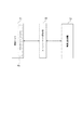
すなわち、仮に図16に示すような構造を持つ記録ヘッドを用いて、図17に示すような画像の画像情報を転送する場合、図18に示すようにYの先頭ラスタを基準にして、Mは32ラスタ、Cは64ラスタ、Bkは96ラスタ分の位置オフセットを付加して送付される。
【0012】
つまり、Yの33ラスタ目の画像データに引き続いて、Mの1ラスタ目の画像データが、Yの97ラスタ目の画像データに引き続いて、Mの65ラスタ目の画像データ、Cの33ラスタ目の画像データ、Bkの1ラスタ目の画像データが送付される方法である(以後、このような画像情報の転送方法を「オフセット転送」と称する)。
【0013】
このようなオフセット転送を用いることで、画像出力装置において画像データを展開したビットマップのメモリーエリアを大幅に削減することを可能としていた。この場合であっても、記録媒体の紙型が単票である限りは、上記のラスタ画像データ転送命令、ラスタ(副走査方向)位置移動命令、頁内ラスタ数指定命令、改頁命令を組み合わせることにより、同一ラスタを構成する各色が同時に送られる方法と同様の命令体系で記録装置の制御が可能であった。
【0014】
また従来は、OA機器を利用してプリントアウトを行う場合、その内部に設置された応用ソフトウェアを通じてこれを行なっていた。例えば、非定型の長尺紙型に対して記録を行う場合には、大別して、応用ソフトウェアに非定型の長尺紙型を用いて記録する設定を行ない、記録する方法と、応用ソフトウェアには、A4版・B5版等の、日常使用される定型紙型を用いて記録する設定を行なっていた。
【0015】
そして、パソコンやワードプロセッサ等のホスト装置内に設置されたプリンタドライバソフトウェアにおいて、長尺紙型を、定型紙型がすきまなく副走査方向に連続したものとして処理することにより記録していた。
【0016】
前者の方法を採用した場合、長尺紙型に記録することのできる応用ソフトウェアは、予め長尺紙型への記録を前提として設計されたものに限られてしまう。この点、後者の方法では、応用ソフトウェアは定型紙型に記録することが可能なものであれば、全てのソフトウェアについて長尺紙型への記録が可能となる利点がある。
【0017】
よって、従来は後者の方法を用いて長尺紙型への記録を行うことが、一般的に行われていた。
【0018】
また、近年、インクジェットプリンタ等の画像出力装置の出力物に対しても、郵便物のあて名印刷やあるいは屋外に掲示する垂れ幕印刷の際に、雨滴などによる水の付着によって印刷内容が流れて判読不能とならぬよう、もしくは判読不能とならぬまでも著しく印刷面を汚損せぬように耐水性の向上が求められている。この解決策の一として、インクと反応させることにより、耐水性を強化することを目的とした耐水強化剤を、印字時に同時に印字箇所に吐出することによって、耐水性を実現したプリントシステムが実現されている。
【0019】
このようなプリントシステムに於いては一般に、印刷に用いられるBk,C,M,Y,などのインクを吐出するためのデータを参照して、これらに対応したパターンの耐水強化剤用のデータを作成し、作成されたデータを各色の印字データと同様の印字機構を用いて印刷を行っている。
【0020】
耐水強化剤の吐出パターン作成法については、例えば同一箇所に印字される各色の印字データの論理和を計算し、これを耐水強化剤のための印字データとして用いることにより、画像を形成するドットが打たれる箇所には必ず耐水強化剤のドットも打たれることが保証される、などの方法が考えられる。
【0021】
ところで、この耐水強化剤の吐出パターンを決定するための処理は、従来プリンタ内部のソフトウェア/ハードウェアを用いて実行されていた。この方法を用いる利点は、プリンタが受信する画像データの形式として、耐水強化剤のある/なしを意識することなく、同一の画像データを送付すれば良いということ、すなわち、少なくとも印刷にかかわる画像データ部分についてはホスト装置内部で耐水強化剤の有無を意識することなく、共通のものが使える、ということにあった。
【0022】
【発明が解決しようとする課題】
しかしながら、上述したように画像出力装置内部で行っていた処理の一部を、画像出力装置用ドライバソフトウェアに移行せしめる場合において、例えば、かかる処理内容をそれぞれサブルーチンとして個別にドライバ内部に実現するときは、単にその都度プログラムインターフェイスの設計を行わなければならないのみならず、メモリ上にロードされるドライバソフトウェアのコード量の増大をもたらすことになる。
【0023】
さらに、これらのルーチンが画像出力装置の個別のハードウェアに依存するものであるが故に、個別の画像出力装置の実装に通じないプログラム設計者にとっての一般的な可読性を損ない、ソフトウェアの保守及び管理の上でも大きな障害となる。
【0024】
また、従来の「オフセット転送」方式を用いて、ホスト装置内に設置されたプリンタドライバソフトウェアにおいて、長尺紙型を、定型紙型がすきまなく副走査方向に連続したものとして処理することにより記録する方法を採用する場合、前後のページの間の繋ぎの部分での改頁命令の処理方法において問題が発生する。
【0025】
例えば、図17に示すような、副走査方向に複数頁が連続した画像の画像情報を、つなぎ目のないように転送する場合、画像データは図18に示すように、改頁命令によって発生する空白領域も、各色毎にオフセットを持った形で送られるべきである。
【0026】
ところが色毎に基準位置が異なっているために、例えばYを基準色として、この基準色に合わせて改頁命令が送られたとしても、他の色については、基準色よりそれぞれのオフセット値分だけ遅れたラスタデータが送付されているために、直ちに基準色のタイミングに合わせた改頁命令の処理を行うことができない。
【0027】
また、プリンタ装置内で、上記耐水強化剤のためのデータを生成する手順を考えると
・ホスト装置から印字データを取得し、メモリ上に書き込み▲1▼
・メモリ上に展開された印字データを読みだし、実際の印刷イメージに変換して再びメモリ上に書き出し▲2▼
・上記印刷イメージを、同一箇所に印字される各々の色について読みだし▲3▼
・上記をもとに、耐水強化剤のパターンを決定し、メモリ上に書き込み▲4▼
・▲2▼および▲4▼によって得られた実際の印字イメージを印字ヘッドに転送▲5▼
という手順を実行することが必要となる。耐水強化剤を用いない場合と比較して手順▲3▼および▲4▼があらたに追加されることになる。あるプリンタ装置の実装例では
▲1▼専用回路によって、DMA転送
▲2▼CPUによるソフトウェア処理
▲3▼CPUによるソフトウェア処理
▲4▼CPUによるソフトウェア処理
▲5▼専用回路によって、DMA転送
のように実装されている。この実装例について、データバスを流れる画像データのトラフィックを比較すると
▲1▼無1.0 有1.0
▲2▼無2.0 有2.0
▲3▼無0.0 有1.0
▲4▼無0.0 有1.25
▲5▼無1.0 有1.25
となり、
データバスを流れるデータ4.0:6.5…1.625倍
CPUが処理するデータ2.0:4.25…2.125倍
と、飛躍的に増加することになる。この場合にはバスを流れるデータの大部分は画像データが占有すると考えても良いので、上記機能をプリンタ内部に実装することを考えた場合には、耐水強化剤のためのデータ作成を必要しない場合と比較して、動作クロックの向上/データバスの幅の拡張などの方法を用いて単位時間あたりのデータ処理量をあげることが必要となり、いずれについても少なからぬコストの上昇を招いてしまうことは避け難い。
【0028】
本発明は上記従来の問題点に鑑み、画像出力装置内部で行っていた処理の一部を画像出力装置用ドライバソフトウェアに移行する場合において、画像出力装置の個別の実装に依存するプログラム部品の作成を容易にして、ドライバソフトウェアのコード量の増大を抑制しかつソフトウェアの保守及び管理面での向上を可能にする情報処理装置、データ処理方法、情報処理システム、及びコンピュータ読み取り可能な記憶媒体を提供することを目的とする。
【0029】
また、本発明の目的は、プリンタのメモリ等のハードウェア規模をできるだけ小さくし、安価なプリンタを提供することにある。
【0030】
また、本発明の目的は、プリンタドライバプログラムの開発を容易に行うことにある。
【0032】
【課題を解決するための手段】
上記目的を達成するために本発明の情報処理装置は、
本発明の情報処理装置は、
プリンタの印刷ヘッドによらない、画像情報を色変換し量子化する、共通画像処理を実行する、インストールされた共通処理モジュールと、プリンタの印刷ヘッドに対応する、共通処理モジュールで量子化された画像情報から印刷ヘッドの色毎の記録素子の構成に応じた色毎に固有のオフセットのついた画像情報を作成する、インストールされた個別処理モジュールとを記憶する記憶手段と、
前記記憶手段に記憶された共通処理モジュールと個別処理モジュールを実行する実行手段とを有し、
前記インストールされた個別処理モジュールは、プリンタの印刷ヘッドに対応しない個別処理モジュールを含まないことを特徴とする。
【0033】
また、本発明の情報処理装置は、
プリンタで印刷される画像情報を生成する情報処理装置であって、
画像情報の色変換処理と量子化処理を行う、複数のプリンタに対して使用されるインストールされた共通処理モジュールと、
前記共通処理モジュールで量子化処理された画像情報から印刷ヘッドの色毎の記録素子の構成に応じた色毎に固有のオフセットのついた画像情報を作成するインストールされた個別処理モジュールと、
前記個別処理モジュールで処理された画像情報を出力する出力手段とを有し、
前記インストールされた個別処理モジュールは、プリンタの印刷ヘッドに対応しない個別処理モジュールを含まないことを特徴とする。
【0034】
また、本発明の情報処理装置は、
画像情報の色変換処理と量子化処理を行う、複数のプリンタに対して使用される共通処理モジュールと、
前記共通処理モジュールで量子化処理された画像情報から印刷ヘッドの色毎の記録素子の構成に応じた色毎に固有のオフセットのついた画像情報を作成する個別処理モジュールと、
前記個別処理モジュールを選択する選択手段とを有し、
前記選択手段による選択は、モジュールをインストールする際に実行されることを特徴とする。
【0036】
また、本発明のデータ処理方法は、
プリンタの印刷ヘッドによらない、画像情報を色変換し量子化する、共通画像処理を実行する、インストールされた共通処理モジュールと、プリンタの印刷ヘッドに対応する、共通処理モジュールで量子化された画像情報から印刷ヘッドの色毎の記録素子の構成に応じた色毎に固有のオフセットのついた画像情報を作成する、インストールされた個別処理モジュールと利用するデータ処理方法であって、
記憶手段に記憶された共通処理モジュールと個別処理モジュールを実行し、
前記インストールされた個別処理モジュールは、プリンタの印刷ヘッドに対応しない個別処理モジュールを含まないことを特徴とするデータ処理方法。
【0037】
また、本発明のデータ処理方法は、
プリンタで印刷される画像情報を生成するデータ処理方法であって、
画像情報の色変換処理と量子化処理を行う、複数のプリンタに対して使用されるインストールされた共通処理モジュールと、前記共通処理モジュールで量子化処理された画像情報から印刷ヘッドの色毎の記録素子の構成に応じた色毎に固有のオフセットのついた画像情報を作成するインストールされた個別処理モジュールとを利用し、
前記個別処理モジュールで処理された画像情報を出力し、
前記インストールされた個別処理モジュールは、プリンタの印刷ヘッドに対応しない個別処理モジュールを含まないことを特徴とする。
【0038】
また、本発明のデータ処理方法は、
画像情報の色変換処理と量子化処理を行う、複数のプリンタに対して使用される共通処理モジュールと、前記共通処理モジュールで量子化処理された画像情報から印刷ヘッドの色毎の記録素子の構成に応じた色毎に固有のオフセットのついた画像情報を作成する個別処理モジュールとを利用するデータ処理方法であって、
前記個別処理モジュールを選択してインストールすることを特徴とする。
【0039】
また、本発明の記憶媒体は、
プリンタの印刷ヘッドによらない、画像情報を色変換し量子化する、インストールされた共通画像処理を実行する共通処理モジュールと、
プリンタの印刷ヘッドに対応する、共通処理モジュールで量子化された画像情報から印刷ヘッドの色毎の記録素子の構成に応じた色毎に固有のオフセットのついた画像情報を作成する、インストールされた個別処理モジュールと、
前記共通処理モジュールと個別処理モジュールを実行する実行モジュールとをコンピュータに実現させるためのプログラムを記憶した記憶媒体であって、
前記インストールされた個別処理モジュールは、プリンタの印刷ヘッドに対応しない個別処理モジュールを含まないことを特徴とする。
また、本発明の記憶媒体は、
プリンタで印刷される画像情報を生成するデータ処理方法であって、
画像情報の色変換処理と量子化処理を行う、複数のプリンタに対して使用されるインストールされた共通処理モジュールと、
前記共通処理モジュールで量子化処理された画像情報から印刷ヘッドの色毎の記録素子の構成に応じた色毎に固有のオフセットのついた画像情報を作成するインストールされた個別処理モジュールと、
前記個別処理モジュールで処理された画像情報を出力する出力モジュールとをコンピュータに実現させるためのプログラムを記憶した記憶媒体であって、
前記インストールされた個別処理モジュールは、プリンタの印刷ヘッドに対応しない個別処理モジュールを含まないことを特徴とする。
また、本発明の記憶媒体は、
画像情報の色変換処理と量子化処理を行う、複数のプリンタに対して使用される共通処理モジュールと、
前記共通処理モジュールで量子化処理された画像情報から印刷ヘッドの色毎の記録素子の構成に応じた色毎に固有のオフセットのついた画像情報を作成する個別処理モジュールと、
前記個別処理モジュールを選択してインストールする選択モジュールとをコンピュータに実現させるためのプログラムを記憶したことを特徴とする。
また、本発明の記憶媒体は、
プリンタの印刷ヘッドによらない、画像情報を色変換し量子化する、共通画像処理を供給する、インストールされた共通処理モジュールと、
プリンタの印刷ヘッドに対応する、共通処理モジュールで量子化された画像情報から印刷ヘッドの色毎の記録素子の構成に応じた色毎に固有のオフセットのついた画像情報を作成する、インストールされた個別の処理モジュールとをコンピュータに実現させるためのプログラムを記憶した記憶媒体であって、
前記インストールされた個別処理モジュールは、プリンタの印刷ヘッドに対応しない個別処理モジュールを含まないことを特徴とする。
【0040】
【発明の実施の形態】
以下、図面を参照して本発明の実施の形態を説明する。
【0041】
(第1実施形態)
図1は、本発明の第1実施形態に係る情報処理システムで用いられるドライバソフトウェアの構造を示すブロック図である。また、図2は、本発明の第1実施形態に係る情報処理システムの概略構成を示すブロック図である。
【0042】
まず、図2において、本実施形態の情報処理システムは、パソコン等で構成されるホスト装置51と、プリンタ等で構成される画像出力装置52とを備え、これらの間が双方向インターフェース53を介して接続されている。そして、ホスト装置51のメモリには、本発明のドライバソフトウェア54がロードされている。
【0043】
本発明では、ドライバソフトウェアにおける、画像出力装置の機種に依存した画像情報加工作業の多くが、量子化された画像情報に対して行われることに着目し、ここの部分に統一された入出力インターフェイスを持つ複数のモジュール群(図1の35−1,35−2)を導入することにより、前述した問題点の解決を試みている。すなわち、画像出力装置に個別に依存する部分を統一的に扱い得るプログラム上のインターフェイス手段を提供することにより、画像処理装置の個別の実装に依存するプログラム部品の作成を容易ならしめ、かつドライバソフトウェアの根幹処理部分を個別の画像処理装置から独立した構造にすることを可能にしている。
【0044】
量子化量に変換された線分割化画像は、統一された入出力インターフェイスを持つモジュール群の何れかにて画像出力装置固有の画像処理が施され、さらにデータ圧縮/印字コマンドが付加した上で、作成されたデータをOS(オペレーティングシステム)に用意されたスプーラを通じて画像出力装置52へ渡すことになる。
【0045】
以下、図1と共に図3及び図4のフローチャートを参照して、アプリケーションソフトウェアが画像出力装置へ画像を出力する場合について、具体的に説明する。
【0046】
図1に示すように、アプリケーションソフトウェアの階層には、アプリケーションソフトウェア11が設けられ、OSの階層には、アプリケーションソフトウェア11からの描画命令を受け取る描画処理インターフェース21と、生成した画像データをインクジェットプリンタ等の画像出力装置52へ渡すスプーラ22とが設けられている。
【0047】
そして、ドライバソフトウェアの階層には、装置固有の表現形式が記憶された装置固有描画手段31−1,31−2,…,31−nと、OSからの線分割化画像情報を受け取る線分割化画像情報受取り手段32と、ドライバ内部の表色系からデバイス固有の表色系への変換を行う色特性変換手段33と、デバイスの各画素の状態を表す量子化量への変換を行うハーフトーニング手段34と、上述した本発明の複数のモジュール35−1,35−2と、このモジュール35−1,35−2の切り替えを行う仮想スイッチ36−1,36−2とが設けられている。
【0048】
ここで、モジュール35−1,35−2は、共に前述したように本発明でいうところの統一された入出力インターフェイスを持つモジュール群であり、例えば、モジュール35−1は、耐水強化剤用の吐出データを必要としない通常のYMCKヘッドの画像出力装置のためのモジュールであり、モジュール35−2は、通常のYMCKヘッドと耐水強化剤用ヘッドとから構成される画像出力装置の耐水強化剤用の吐出パターンを決定する論理手段を備えたモジュールである。
【0049】
なお、耐水強化剤用の吐出データとは、通常のYMCKヘッド用の2値データにYMCKのデータの論理和を取った耐水強化剤用ヘッド用のデータが追加されたデータのことである。
【0050】
また、仮想スイッチ36−1,36−2は、プログラム内に設けられた仮想のスイッチであり、どの画像出力装置を対象とするか、あるいはその画像を生成する際に画像出力装置のどの機能を用いるかに応じて、モジュール35−1,35−2を切り替える。具体的には、プリンタドライバの表示画面で、ユーザがプリンタを選択し、選択されたプリンタでの印刷実行指示を行った際に、選択されたプリンタのヘッドに対応するモジュールに切り替えられる。
【0051】
アプリケーションソフトウェア11が画像出力装置52へ画像を出力する場合は、まず、アプリケーションソフトウェア11がOSの描画処理インターフェース21を通じて、文字・線分・図形・ビットマップなどの描画命令を発行する(ステップS1)。
【0052】
画面/紙面を構成する描画命令が完結すると(ステップS2)、OSは、ドライバソフトウェア内部の装置固有描画手段31−1,31−2,…,31−nを呼び出しつつ、各描画命令を、OSの内部形式から装置固有の表現形式(各描画単位を線分割化したもの)に変換し(ステップS3)、しかる後に画面/紙面を線分割化した画像情報としてドライバソフトウェアへ渡す(ステップS4)。
【0053】
ドライバソフトウェア内部では、色特性変換手段33によってデバイスの色特性を補正すると共に、ドライバソフトウェア内部の表色系からデバイス固有の表色系への変換を行い(ステップS5)、さらにハーフトーニング手段34によってデバイスの各画素の状態を表す量子化量への変換(ハーフトーニング)を行う(ステップS6)。なお、ここでの量子化量への変換とは、画像出力装置の処理するデータの形態に対応し、例えば、画像出力装置による記録が2値データに基づき行われる場合は、2値化し、画像出力装置による記録が多値データ(濃淡インクによる記録、大小インクによる記録を行うため)に基づき行われる場合は、多値化されることである。
【0054】
モジュール35−1,35−2は、いずれも量子化(2値化、多値化)された画像データを受け取る(ステップS7)。モジュール35−1,35−2は、量子化された画像情報を相異なる方法にて画像出力装置の特性に合わせて加工する。モジュール35−2においては、受領した量子化データを参照しつつ耐水強化剤の吐出パターンを決定し、更に両モジュールともにデータ圧縮、コマンドヘッダの付加を行う(ステップS8)。そして、連動して動作する仮想スイッチ36−1,36−2は、画像を出力しようとする利用者に選択された画像出力装置52の種類に応じてモジュール35−1,35−2を切り替える(ステップS9)。
【0055】
その後、モジュール35−1,35−2は、OS内部に設けられたスプーラ22に生成したデータを受け渡し(ステップS10)、画像出力装置52へのデータ出力を果たす(ステップS11)。
【0056】
なお、本実施形態では、図3及び図4のフローチャートに従ったプログラムをホスト装置51内の記憶装置に格納し動作することにより、上述の制御方法を実現させることが可能となる。
【0057】
このように本実施形態では、画像出力装置に個別に依存する部分を統一的に扱い得るプログラム上のインターフェース手段であるモジュール35−1,35−2を設けたので、画像処理装置の個別の実装に依存するプログラム部品の作成を容易にすることができる。これにより、画像出力装置内部で行っていた処理の一部をドライバソフトウェアに移行する場合において、ドライバソフトウェアのコード量の増大を抑制することができる。
【0058】
また、ドライバソフトウェアの根幹処理部分を個別の画像処理装置から独立した構造にすることができるので、ドライバソフトウェアと画像出力装置間のデータ処理の分担を、ドライバソフトウェアの構成を損なうことなく柔軟に変更することが可能になり、ソフトウェアの保守及び管理面で有利となる。
【0059】
(第2実施形態)
図5は、本発明の第2実施形態に係る情報処理システムで用いられるドライバソフトウェアの構造を示すブロック図であり、図1と共通の要素には同一の符号が付されている。
【0060】
上記第1実施形態では、画像を出力しようとする利用者が画像出力装置52を選択する際に、仮想スイッチ36−1,36−2を用いて画像出力装置52の種類に応じてモジュール35−1,35−2を切り替えるようにした。これに対して、本実施形態では、ホスト装置51と画像出力装置52を結ぶ双方向インターフェイス53を通じて現在接続されている画像出力装置52の種類を自動的に受取り、モジュール35−1,35−2を切り替えることにより、より利便性を向上させている。
【0061】
すなわち、OSのスプーラ22Aは、双方向インターフェイス53を通じて現在接続されている画像出力装置52からその種類(プリントヘッドの種類)を表すデータを受取り、これを基に仮想スイッチ36−1,36−2の切り替えを行う。その結果、モジュール35−1,35−2が画像出力装置52の種類に応じて切り替えられ、その後、モジュール35−1,35−2からスプーラ22Aに対して生成データが渡されて、画像出力装置52へのデータ出力を果たす。
【0062】
本発明は、上述した実施形態の装置に限定されず、複数の機器から構成されるシステムに適用しても、ひとつの機器から成る装置に適用してもよい。前述したを実施形態の機能を実現するソフトウエアのプログラムコードを記憶した記憶媒体も、システムあるいは装置に供給し、そのシステムあるいは装置もコンピューター(またはCPUやMPU)が記憶媒体に格納されたプログラムコードを読み出し実行することによっても、完成されることは言うまでもない。
【0063】
この場合、記憶媒体から読み出されたプログラムコード自体が前述した実施形態の機能を実現することになり、そのプログラムコードを記憶した記憶媒体は本発明を構成することになる。プログラムコードを供給するための記憶媒体としては、例えば、フロッピーディスク、ハードディスク、光ディスク、光磁気ディスク、CD−ROM、CD−R、磁気テープ、不揮発性のメモリーカード、ROMを用いることができる。また、コンピューターが読み出したプログラムコードを実行することにより、前述した実施形態の機能が実現されるだけではなく、そのプログラムコードの指示に基づき、コンピューター上で稼動しているOSなどが実際の処理の一部または全部を行い、その処理によって前述した実施形態の機能が実現される場合も含まれることは言うまでもない。
【0064】
さらに、記憶媒体から読み出されたプログラムコードが、コンピューターに挿入された機能拡張ボードやコンピューターに接続された機能拡張ユニットに備わるメモリに書き込まれた後、次のプログラムコードを指示に基づき、その拡張機能を拡張ボードや機能を拡張ユニットに備わるCPUなどが実際の処理に行って実際の処理の一部または全部を行い、その処理によって前述した実施形態の機能が実現される場合も含まれることは言うまでもない。
【0065】
また、他のモジュールとして、YMCKヘッドが副走査方向に並んだ画像出力装置用に、ヘッドに合せてデータを転送するためのオフセット転送プログラムを含むモジュール35−3(図11)を備えることもできる。
【0066】
また、本実施の形態におけるモジュールの切り替えは、プリンタドライバインストール時に実行することもできる。
【0067】
以上詳述したように、本実施の形態によれば、モジュールは、出力装置に個別に依存する部分を統一的に扱い得るインターフェース手段として機能するので、出力装置の個別の実装に依存するプログラム部品の作成を容易ならしめることができ、例えばドライバソフトウェアで構成される生成手段のコード量の増大を抑制することが可能になる。さらに、ドライバソフトウェアの根幹処理部分を個別の出力装置から独立した構造にすることができるので、ドライバソフトウェアと出力装置間のデータ処理の分担を、ドライバソフトウェアの構成を損なうことなく柔軟に変更することができ、ソフトウェアの保守及び管理面において有利となる。
【0068】
また、本発明の実施の形態によれば、出力装置の種類を自動的に取得することができるので、より利便性が向上する。
【0069】
次に画像出力装置52の具体的構成について説明する。
【0070】
(画像出力装置本体の概略説明)
図6は、本発明の代表的な実施の形態であるインクジェットプリンタIJRAの構成の概要を示す外観斜視図である。図6において、駆動モータ5013の正逆回転に連動して駆動力伝達ギア5009〜5011を介して回転するリードスクリュー5005の螺旋溝5004に対して係合するキャリッジHCはピン(不図示)を有し、ガイドレール5003に支持されて矢印a,b方向を往復移動する。キャリッジHCには、記録ヘッドIJHとインクタンクITとを内蔵した一体型インクジェットカートリッジIJCが搭載されている。5002は紙押え板であり、キャリッジHCの移動方向にわたって記録用紙Pをプラテン5000に対して押圧する。5007,5008はフォトカプラで、キャリッジのレバー5006のこの域での存在を確認して、モータ5013の回転方向切り換え等を行うためのホームポジション検知器である。5016は記録ヘッドIJHの前面をキャップするキャップ部材5022を支持する部材で、5015はこのキャップ内を吸引する吸引器で、キャップ内開口5023を介して記録ヘッドの吸引回復を行う。5017はクリーニングブレードで、5019はこのブレードを前後方向に移動可能にする部材であり、本体支持板5018にこれらが支持されている。ブレードは、この形態でなく周知のクリーニングブレードが本例に適用できることは言うまでもない。又、5021は、吸引回復の吸引を開始するためのレバーで、キャリッジと係合するカム5020の移動に伴って移動し、駆動モータからの駆動力がクラッチ切り換え等の公知の伝達機構で移動制御される。
【0071】
これらのキャッピング、クリーニング、吸引回復は、キャリッジがホームポジション側の領域に来た時にリードスクリュー5005の作用によってそれらの対応位置で所望の処理が行えるように構成されているが、周知のタイミングで所望の動作を行うようにすれば、本例にはいずれも適用できる。
【0072】
<制御構成の説明>
次に、上述した装置の記録制御を実行するための制御構成について説明する。
【0073】
図7はインクジェットプリンタIJRAの制御回路の構成を示すブロック図である。制御回路を示す同図において、1700は記録信号を入力するインタフェース、1701はMPU、1702はMPU1701が実行する制御プログラムを格納するROM、1703は各種データ(上記記録信号やヘッドに供給される記録データ等)を保存しておくDRAMである。1704は記録ヘッド1708に対する記録データの供給制御を行うゲートアレイ(G.A.)であり、インタフェース1700、MPU1701、RAM1703間のデータ転送制御も行う。1710は記録ヘッド1708を搬送するためのキャリアモータ、1709は記録紙搬送のための搬送モータである。1705は記録ヘッドを駆動するヘッドドライバ、1706,1707はそれぞれ搬送モータ1709、キャリアモータ1710を駆動するためのモータドライバである。
【0074】
上記制御構成の動作を説明すると、インタフェース1700に記録信号が入るとゲートアレイ1704とMPU1701との間で記録信号がプリント用の記録データに変換される。そして、モータドライバ1706、1707が駆動されると共に、ヘッドドライバ1705に送られた記録データに従って記録ヘッドが駆動され、記録が行われる。
【0075】
なお、上述のように、インクタンクITと記録ヘッドIJHとは一体的に形成されて交換可能なインクカートリッジIJCを構成しても良いが、これらインクタンクITと記録ヘッドIJHとを分離可能に構成して、インクがなくなったときにインクタンクITだけを交換できるようにしても良い。
【0076】
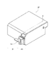
図8は、インクタンクとヘッドとが分離可能なインクカートリッジIJCの構成を示す外観斜視図である。インクカートリッジIJCは、図8に示すように、境界線Kの位置でインクタンクITと記録ヘッドIJHとが分離可能である。インクカートリッジIJCにはこれがキャリッジHCに搭載されたときには、キャリッジHC側から供給される電気信号を受け取るための電極(不図示)が設けられており、この電気信号によって、前述のように記録ヘッドIJHが駆動されてインクが吐出される。
【0077】
なお、図8において、500はインク吐出口列である。また、インクタンクITにはインクを保持するために繊維質状もしくは多孔質状のインク吸収体が設けられており、そのインク吸収体によってインクが保持される。
【0078】
なお、以上の実施形態において、記録ヘッドから吐出される液滴はインクであるとして説明し、さらにインクタンクに収容される液体はインクであるとして説明したが、その収容物はインクに限定されるものではない。例えば、記録画像の定着性や耐水性を高めたり、その画像品質を高めたりするために記録媒体に対して吐出される処理液のようなものがインクタンクに収容されていても良い。
【0079】
以上の実施形態は、特にインクジェット記録方式の中でも、インク吐出を行わせるために利用されるエネルギーとして熱エネルギーを発生する手段(例えば電気熱変換体やレーザ光等)を備え、前記熱エネルギーによりインクの状態変化を生起させる方式を用いることにより記録の高密度化、高精細化が達成できる。
【0080】
その代表的な構成や原理については、例えば、米国特許第4723129号明細書、同第4740796号明細書に開示されている基本的な原理を用いて行うものが好ましい。この方式はいわゆるオンデマンド型、コンティニュアス型のいずれにも適用可能であるが、特に、オンデマンド型の場合には、液体(インク)が保持されているシートや液路に対応して配置されている電気熱変換体に、記録情報に対応していて膜沸騰を越える急速な温度上昇を与える少なくとも1つの駆動信号を印加することによって、電気熱変換体に熱エネルギーを発生せしめ、記録ヘッドの熱作用面に膜沸騰を生じさせて、結果的にこの駆動信号に1対1で対応した液体(インク)内の気泡を形成できるので有効である。この気泡の成長、収縮により吐出用開口を介して液体(インク)を吐出させて、少なくとも1つの滴を形成する。この駆動信号をパルス形状とすると、即時適切に気泡の成長収縮が行われるので、特に応答性に優れた液体(インク)の吐出が達成でき、より好ましい。
【0081】
このパルス形状の駆動信号としては、米国特許第4463359号明細書、同第4345262号明細書に記載されているようなものが適している。なお、上記熱作用面の温度上昇率に関する発明の米国特許第4313124号明細書に記載されている条件を採用すると、さらに優れた記録を行うことができる。
【0082】
記録ヘッドの構成としては、上述の各明細書に開示されているような吐出口、液路、電気熱変換体の組み合わせ構成(直線状液流路または直角液流路)の他に熱作用面が屈曲する領域に配置されている構成を開示する米国特許第4558333号明細書、米国特許第4459600号明細書を用いた構成も本発明に含まれるものである。加えて、複数の電気熱変換体に対して、共通するスロットを電気熱変換体の吐出部とする構成を開示する特開昭59−123670号公報や熱エネルギーの圧力波を吸収する開口を吐出部に対応させる構成を開示する特開昭59−138461号公報に基づいた構成としても良い。
【0083】
さらに、記録装置が記録できる最大記録媒体の幅に対応した長さを有するフルラインタイプの記録ヘッドとしては、上述した明細書に開示されているような複数記録ヘッドの組み合わせによってその長さを満たす構成や、一体的に形成された1個の記録ヘッドとしての構成のいずれでもよい。
【0084】
加えて、上記の実施形態で説明した記録ヘッド自体に一体的にインクタンクが設けられたカートリッジタイプの記録ヘッドのみならず、装置本体に装着されることで、装置本体との電気的な接続や装置本体からのインクの供給が可能になる交換自在のチップタイプの記録ヘッドを用いてもよい。
【0085】
また、以上説明した記録装置の構成に、記録ヘッドに対する回復手段、予備的な手段等を付加することは記録動作を一層安定にできるので好ましいものである。これらを具体的に挙げれば、記録ヘッドに対してのキャッピング手段、クリーニング手段、加圧あるいは吸引手段、電気熱変換体あるいはこれとは別の加熱素子あるいはこれらの組み合わせによる予備加熱手段などがある。また、記録とは別の吐出を行う予備吐出モードを備えることも安定した記録を行うために有効である。
【0086】
さらに、記録装置の記録モードとしては黒色等の主流色のみの記録モードだけではなく、記録ヘッドを一体的に構成するか複数個の組み合わせによってでも良いが、異なる色の複色カラー、または混色によるフルカラーの少なくとも1つを備えた装置とすることもできる。
【0087】
以上説明した実施の形態においては、インクが液体であることを前提として説明しているが、室温やそれ以下で固化するインクであっても、室温で軟化もしくは液化するものを用いても良く、あるいはインクジェット方式ではインク自体を30°C以上70°C以下の範囲内で温度調整を行ってインクの粘性を安定吐出範囲にあるように温度制御するものが一般的であるから、使用記録信号付与時にインクが液状をなすものであればよい。
【0088】
加えて、積極的に熱エネルギーによる昇温をインクの固形状態から液体状態への状態変化のエネルギーとして使用せしめることで積極的に防止するため、またはインクの蒸発を防止するため、放置状態で固化し加熱によって液化するインクを用いても良い。いずれにしても熱エネルギーの記録信号に応じた付与によってインクが液化し、液状インクが吐出されるものや、記録媒体に到達する時点では既に固化し始めるもの等のような、熱エネルギーの付与によって初めて液化する性質のインクを使用する場合も本発明は適用可能である。このような場合インクは、特開昭54−56847号公報あるいは特開昭60−71260号公報に記載されるような、多孔質シート凹部または貫通孔に液状または固形物として保持された状態で、電気熱変換体に対して対向するような形態としてもよい。本発明においては、上述した各インクに対して最も有効なものは、上述した膜沸騰方式を実行するものである。
【0089】
さらに加えて、本発明に係る記録装置の形態としては、コンピュータ等の情報処理機器の画像出力端末として一体または別体に設けられるものの他、リーダ等と組み合わせた複写装置、さらには送受信機能を有するファクシミリ装置の形態を取るものであっても良い。
【0090】
(ホスト装置51と画像出力装置52のハードウェア構成)
次に、ホスト装置51と画像出力装置52のハードウェア構成について説明する。
【0091】
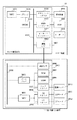
図9において、1000はホスト装置本体、51は周辺装置を含めたホスト装置全体である。また、52は画像出力装置本体、3010は印刷記録ヘッド、3011は印刷ヘッドを搬送するキャリアを駆動するキャリアモータ、3012は用紙を搬送する搬送モータである。画像出力装置本体52は、上述した図2に示す概略構成を具体的な構成として達成した例を示している。
【0092】
ホスト装置本体51において、1001はDRAM1003に格納されている制御手順に従ってホスト装置の全体制御を司るMPU、1002はシステム全体を接続するバス、1003はMPU1001が実行するプログラムやデータ等を一時記憶するDRAM、1004はシステムバスとメモリバス、MPUを接続するブリッジ、1005はCRTにグラフィック情報を表示するための制御機能を備えたグラフィックアダプタである。
【0093】
又、1006はHDD装置2002とのインタフェースを司るHDDコントローラ、1007はキーボードとのインタフェースを司るキーボードコントローラ、1008はIEEE1284規格に従って記録装置3000との間の通信を司る、パラレルインターフェイスである通信I/Fである。
【0094】
ホスト装置本体51には、グラフィックアダプタ1005を介して操作者にグラフィック情報等を表示する表示装置2001が接続されており、本実施の形態例では接続陰極線管(CRT)表示装置となっている。更に、プログラムやデータが格納された大容量記憶装置であるハードディスクドライブ(HDD)装置2002、キーボード2003が接続されている。
【0095】
画像出力装置本体52において、3001は制御プログラム実行機能と周辺装置制御機能とを兼ね備えた、画像出力装置本体52の全体制御を司るMCU(マイクロコントローラユニット)、3002はシステムバス、3003は記録データの印刷ヘッドへの供給、メモリアドレスデコーディング、キャリアモータへの制御パルス発生機構等を制御回路として内部に納めたゲートアレイである。
【0096】
また、3004はMCU3001が実行する制御プログラムやホスト印刷情報等を格納するROM、3005はDRAMであり、DRAM3005には各種データ(画像記録情報やヘッドに供給される記録データ等)を保存する。
【0097】
3006はIEEE1284規格に則りホスト装置51との間の通信を司るパラレルインターフェイスである通信I/F、3007はゲートアレイ3003から出力されたヘッド記録信号に基づき、記録ヘッドを駆動する電気信号に変換するヘッドドライバである。
【0098】
3008はゲートアレイ3003から出力されるキャリアモータ制御パルスを、実際にキャリアモータを駆動する電気信号に変換するモータドライバ、3009は前記MCUから出力された搬送モータ制御パルスを、実際に搬送モータを駆動する電気信号に変換するモータドライバである。
【0099】
つぎに、本実施例で用いる記録ヘッドを図10を参照して説明する。図10は第1の実施の形態例の画像出力装置で用いる記録ヘッドの構成例を示す図である。
【0100】
図10に示す本実施の形態例の画像出力装置52の記録ヘッド3010は、Y,M,Cの記録色を記録する記録素子各24素子、Bkの記録色を記録する記録素子64素子を、1チップに構成した記録ヘッドであり、各記録色間の色間に8素子(画素)相当分の色間隙間がある。
【0101】
図10の(a)に示すように、上からY,M,C,Bkの順にノズルn1〜n160が形成されている。また図10の(b)は上記構成の記録ヘッドのチップの例を示しており、Y,M,C,Bkの記録素子としての発熱体Hが配され、各色毎の記録素子のグループ間に8画素(ノズル間隔)相当分の隙間が構成されている。
【0102】
この隙間は必ずしも必要なものではないが、記録ヘッド3010のチップ上に色毎のインク室を構成していく上で、色間隙間はあった方が構成が容易であるので設けている。
【0103】
尚、本実施例では各色毎のインク室や各ノズル、インク注入路などは型成型によるモールド部材で構成し、モールド成型された部材を上記記録ヘッドチップに不図示のバネで押しつけ、バネを含めて封止材で封止することにより構成する。ドライフィルムで上記インク室やノズルを構成する手段であっても、その他の方式で構成する手段であっても本発明に適用可能であるので、詳細な説明は省略する。
【0104】
(オフセット転送プログラムを含むモジュール)
次いで、前述した他のモジュールとしてのオフセット転送プログラムを含むモジュール35−3について具体的に図面を参照しつつ説明する。まず、ホスト装置51に設置されるドライバソフトウェアを図11を参照して説明する。図11は本実施の形態例のドライバソフトウェアの構成を説明するための図である。
【0105】
本実施の形態例のドライバソフトウェアは、図11のCに示される階層で表わされる。
【0106】
図11において、Aはアプリケーションソフトウェア(以下「App」と称す)の階層、Bはオペレーティングシステム(以下「OS」と称す)を構成する階層、Cはドライバソフトウェアの階層を示す。
【0107】
記録装置にAppの11に示すプログラムにおいて、画像を出力しようとする場合、AppはOSの描画処理インターフェイス21を通じて、文字・線分・図形・ビットマップなどの描画命令を発行する。
【0108】
画面/紙面を構成する描画命令が完結すると、OSは各描画命令を、31−1〜31−nで表されるドライバ内部の装置固有の描画手段を呼び出しつつ、OSの内部形式から装置固有の表現形式(各描画単位を線分化したもの)に変換する。この場合には、RGB各色を8ビット/画素で表現される点順次のラスタデータとして33の色補正/色変換手段に渡す。
【0109】
33の色補正/色変換手段では、デバイスの色特性を補正/ドライバ内部の表色系からデバイス固有の表色系への変換を行い、この場合にはKCMY各色8ビット/画素で表現される点順次のラスタデータとしてハーフトーニング手段34に渡す。
【0110】
ハーフトーニング手段34では、デバイスの各画素の状態を表す量子化量への変換を行い、各色1ビット乃至4ビット/ピクセルの線順次データとして、オフセット処理手段37に渡す。オフセット処理手段37においては、印刷ヘッドの構成に応じたオフセット量に従って、色毎に固有の副走査方向オフセットのついたKCMY各色1ビット乃至4ビット/ピクセルの線順次データとして、データ圧縮/コマンド付加手段38に渡す。
【0111】
データ圧縮/コマンド付加手段38では、渡された画像データに基づき、画像転送効率を向上するためにパックビッツ(PackBits)形式による圧縮を施し、印刷コマンドヘッダを付加して、システムのプリントスプーラ22に渡す。
【0112】
システムのプリンタスプーラ22は、通信I/F1008を介してIEEE1284に定められた手順に従って、画像データの画像出力装置52への転送を行なう。
【0113】
上述したオフセット処理手段37の内部の詳細な構成を、図12を参照して具体的に説明する。図12は本実施の形態例におけるオフセット処理手段37で用いるFIFOバッファの詳細構成を説明するための図である。
【0114】
図12のFIFOバッファ9001は、Bkラスタについての情報を96本分蓄えることが可能なFIFOバッファであり、1ラスタの入力に対し、1ラスタの出力を得ることができる。FIFOバッファ9002は、同様に、Mラスタについての情報を64本分蓄えることのできるFIFOバッファである。FIFOバッファ9003は、同様にCラスタについての情報を32本分蓄えることのできるFIFOバッファである。
【0115】
上記3つのFIFOバッファ9001〜9003は、先入れ/先出し手順に従い、ラスタ単位でデータを管理することのできるバッファである。具体的には、各FIFOバッファ9001〜9003は、実際にデータが格納されている領域の先頭アドレスと、データの長さを各バッファの深さ分の組と、バッファ管理用カウンタ(複数の色に対応するページ内ラスタ数カウンタ)CBk(n)、CM(n’)、CC(n”)とを持つ。
【0116】
FIFOバッファに対してデータを入出力する際には、例えばBkラスタについて言えば、CBkn番目のアドレス/長さのフィールドに、バッファに登録すべき不図示のデータの所在を書き込み、しかるのちにCBk(n+1)に記述されたアドレス/長さで示されるデータを取り出し、カウンタをインクリメントする。
【0117】
上記各色に対応するカウンタの値がバッファ容量(深さ)(例えばBkの場合には95)を超えた場合には、カウンタの値を0にリセットする。これらのバッファの内部は、データを扱う前には全てクリアされている。また、1頁分のデータの送出終了による改頁命令の転送時点でも次のデータを扱うことになり、このタイミングでもクリアされる。
【0118】
ハーフトーニング手段34から渡されたBk,M,Cのラスタは、各FIFOバッファの末尾に蓄積され、各FIFOバッファの先頭にあるラスタ、及びハーフトーニング手段34から渡されたYラスタを一組として取り出す。このFIFOバッファ管理機構により、印刷ヘッドの物理的な構成に合わせたラスタデータの作成が可能となる。
【0119】
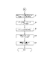
次に、本実施の形態例におけるプリンタドライバにおける全体制御を図13及び図14のフローチャートを参照して説明する。図13は本実施の形態例の図11に示すプリンタドライバの全体制御を示すフローチャート、図14は本実施の形態例のプリンタドライバにおけるギャップ処理を示すフローチャートである。
【0120】
本実施の形態例のプリンタドライバにおいて、画像出力装置52に対して送付されるコマンドとしては各種存在するが、以下の説明は「頁長設定コマンド」、「ラスタ位置移動コマンド」、「ラスタデータ転送コマンド」、「改頁コマンド」の4つのコマンドを送付した場合を例に説明を行なう。
【0121】
まず、最初に、ステップS100において、ページ長設定コマンドを送付する。次いでステップS102において、プリンタドライバのハーフトーニング手段34から、必要に応じて2値化されたnラスタ目のラスタデータ(Bk,Y,M,C)を受け取る。
【0122】
次に、ステップS103において、直前のラスタとの間にギャップが存在するか否かを調べる。ギャップが存在する場合には、図14のステップS200に処理を移す。ちなみに、ページ内で受け取った最初のラスタについては、ページの先頭の1ラスタ目のラスタとの間でギャップを計算する。図14におけるギャップ処理については後述する。
【0123】
一方、ステップS103において直前のラスタとの間にギャップが存在しない場合にはステップS105に進み、スキップ量1のラスタ位置移動コマンドを送出する。続いてステップS106では、図12に示すラスタデータ格納用のFIFO管理バッファに、受け取ったBk,M,C、各ラスタについてのデータを登録する。
【0124】
つぎにステップS107において、FIFO管理バッファの先頭から、保管されていたBk,M,C、の各ラスタを取り出す。ステップS108では、取り出したBk,M,C、の各ラスタ、及び受け取ったYのラスタをそれぞれデータ圧縮する。
【0125】
続いてステップS109において、圧縮された各ラスタデータをプリンタに対して転送できるように、ラスタデータ転送コマンドのコマンドヘッダを付加する。ステップS110では、コマンドヘッダを付加した各色ラスタデータをプリントスプーラB2に渡すことによってOSに送出する。
【0126】
つぎにステップS111で、現在のラスタがページ内の画像データを含む最後のラスタかどうかを判別する。頁内の最後の画像データを含むラスでない場合にはステップS101に戻る。
【0127】
一方、ステップS111において、頁内の最後の画像データを含むラスタの場合にはS112へ進み、頁内の最後の画像データを含むラスタと判定されたラスタと、頁長設定コマンドにて設定されたページ内の最終ラスタとの間にギャップがあるかどうかを判定する。ギャップがある場合には、後述する図14のステップS200のギャップ処理に移る。
【0128】
一方、ステップS112において、頁長設定コマンドにて設定されたページ内の最終ラスタとの間にギャップがない場合にはステップS114に進み、改ページコマンドを送出する。次いで、ステップS115において、現在のページが最終ページであるかどうかを判定する。最終ページでない場合にはステップS101に戻り、次のページのための処理を引き続き継続する。
【0129】
一方、ステップS115で現在の頁が最終ページである場合には、FIFO管理バッファに蓄積されている画像データを、全て画像出力装置52に送付して当該処理を終了する。
【0130】
次に、プリンタードライバ処理におけるギャップ処理に関する処理を図14フローチャートを参照して説明する。図14の処理を実行するのは、ステップS103の判定において直前のラスタとの間にギャップが存在する場合、及びステップS112において頁内の最後の画像データを含むラスタと判定されたラスタと、頁長設定コマンドにて設定されたページ内の最終ラスタとの間にギャップがある場合である。
【0131】
まず、ステップS200において、ギャップ量が0より大きいかどうかを判定する。ここでギャップ量が0の場合にはステップS201に進み、図13のステップS103の処理から当該処理に移行したか否かを調べる。ステップS103の処理から当該処理に移行した場合にはステップS105に進む。
【0132】
一方、ステップS201でステップS103の処理から当該処理に移行したのではなく、ステップS112の処理から当該処理に移行した場合にはステップS114に進む。
【0133】
ステップS200の判定でギャップ量が0より大きい場合にはステップS203に進み、ギャップ量から1を減ずる演算を行う。続いてステップS204においてスキップ量1のラスタ位置移動コマンドを、プリントスプーラ22を介して画像出力装置52に送出する。
【0134】
次いでステップS205において、FIFO管理バッファの末尾に、各色とも白で構成される(画像データを含まない)ラスタを格納する。続いてステップS206において、FIFO管理バッファの先頭から画像データを取り出す。そして、ステップS207においてBk,C,MについてはFIFO管理バッファを通じて取り出した画像データを、Yについては画像データを含まない白(空白)ラスタをデータ圧縮する。
【0135】
つぎにステップS208において、プリンタに転送可能なように、作成した圧縮データに対してコマンドヘッダを付加する。ステップS209においては、圧縮/コマンドヘッダ付加された画像データをプリンタに送付すべく、プリンタスプーラ22に渡しステップS201の処理に戻る。
【0136】
次に、以上に説明した処理に従って通信I/F1008を介して送られてくるこの印刷データ及び印刷制御情報を受取る画像出力装置52の制御を図15のフローチャートを参照して以下に説明する。図15は本実施の形態例の画像出力装置52のコマンド処理を説明するためのフローチャートである。
【0137】
図15において、まずステップS301でホスト装置本体1000のプリンタスプーラ22からコマンドデータを受取る。続いてステップS302以下の処理において受け取ったデータ列がどのコマンドであるかを判別するコマンド種別判別処理を行う。次にそれぞれのコマンドについての制御内容を簡潔に記載する。
【0138】
まずステップS302において受信したコマンドが頁長設定コマンドか否かを判別する。受信したコマンドが頁長設定コマンドであった場合には頁長設定コマンド処理に移行し、現在の基準色(本実施の形態例ではYとする)についての頁内のラスタ位置カウンタが0であり、かつ未だ印刷データを受領していない場合についてのみ、頁長をコマンドで指定された値に設定する。上記の条件を満たしていない場合については、コマンドを無視する。
【0139】
次に、ステップS302において受信したコマンドが頁長設定コマンドでなかった場合にはステップS303に進み、受信コマンドがラスタ位置移動コマンドか否かを判別する。受信したコマンドがラスタ位置移動コマンドであった場合にはラスタ位置移動コマンド処理に移行する。
【0140】
本実施の形態例においては、印刷ラスタデータは1ラスタずつ送付されるのに対し、印刷動作自体は各色複数ノズルを有しているので、次回の印刷動作において、受け取ったラスタデータが、先頭ノズルから何番目のノズルによって印刷されるかを示すカウンタを設けることによって、実際に設置されているノズル数分のラスタデータが揃ってはじめて、印刷を開始することができる。
【0141】
仮に現在のラスタ位置がn番目のノズル位置に対応していると考えて
(n+ラスタ位置移動量 ≦ 各色のノズル総数)の場合、
n+ラスタ位置移動量に、ノズル位置指定カウンタを更新する。
【0142】
一方、(n+ラスタ位置移動量 > 各色のノズル総数)の場合、
印刷バッファの画像データを印刷した後、
(ラスタ位置移動量+ノズル位置指定カウンタの値−1)
分だけ、印刷用紙を副走査方向に移動する制御を行う。
【0143】
しかるのちに、各色それぞれに用意してある、頁内のラスタ位置カウンタに対し、ラスタ位置移動量を加算する。処理を行う。
【0144】
一方、ステップS303で受信コマンドがラスタ位置移動コマンドでなかった場合にはステップS304に進み、コマンドがラスタデータ転送コマンドか否かを判別する。受信したコマンドがラスタデータ転送コマンドであった場合にはラスタデータ転送コマンド処理に移行する。
【0145】
まず前述のノズル位置指定カウンタによって示される、現在のラスタイメージを転送すべき印刷バッファ内部の領域に、受領したK,Y,M,C各色のラスタデータを展開する。但し、前述の頁内のラスタ位置カウンタが頁長設定コマンドによって設定されていた値を超えていた場合には、印刷バッファに対してのラスタデータの展開を行わずに、無視する。
【0146】
一方、ステップS304で受信したコマンドがラスタデータ転送コマンドでなかった場合にはステップS305に進み、受信したコマンドが改頁コマンドか否かを判別する。受信したコマンドが改頁コマンドであった場合には改頁コマンド処理に移行する。
【0147】
そして、前述の頁内のラスタ位置カウンタを、基準色のYについて(0)、Mについて(−32)、Cについて(−64)、Bkについて(一96)の値に初期化する。この操作によって、例えば基準色が2ページ目の1ラスタ目についての処理を行っている際に、他のM,C,Bkについては、前のページの末尾のデータを処理している矛盾を解決している。
【0148】
一方、ステップS306において、受信したコマンドが改頁コマンドでなかった場合には本実施の形態例の画像出力装置52で処理可能なコマンドでないため、受信したデータを読み捨てて再びステップS301に戻り、次のデータの受信に備える。
【0149】
以上説明したように本実施の形態例によれば、パソコンやワープロなどのホスト装置内に設置されたプリンタドライバソフトウェアを用いて、基準色について、改頁命令を発生する直前に、現在設定されている頁内ラスタ数の内の最下端ラスタに対するラスタ(副走査方向)位置移動命令を、ドライバソフトウェアにて内部的に生成し、しかるのちに記録装置に対して改頁命令を送付し、一方、記録装置においては、改頁命令を受信した時点で、頁内部での現在のラスタ位置を管理するカウンタを、それぞれの色毎に定められたオフセット値に応じて初期化することができ、画像出力装置52内のメモリ使用量をオフセット転送を行うことにより削減しつつ、長尺の印刷用紙に対して、これを仮想的に短い紙が連続してすきまなく連結したものとして印刷することが可能になる。
【0150】
以上説明した37のオフセット処理モジュールと38のデータ圧縮/コマンド付加モジュールとを前述したオフセット転送プログラムを含むモジュール35−3とすることができる。
【0151】
以上説明したように実施の形態によれば、画像出力装置内のメモリ使用量をオフセット転送を行うことにより削減しつつ、長尺の印刷用媒体に対して、これを仮想的に短い媒体が連続してすきまなく連結したものとして印刷することが可能になる。更に、処理モジュールを画像出力装置により交換可能な構成を取った場合には、長尺記録媒体に印刷可能でかつ、オフセット転送をするシステムとオフセット転送をしないシステムを柔軟に切り替えることが可能となる。
【0152】
(耐水強化剤用の吐出パターンを決定する論理手段を備えたモジュール)
次いで、前述した耐水強化剤用の吐出パターンを決定する論理手段を備えたモジュール35−2について説明する。まず、ホスト装置に設置されるドライバソフトウェアは図1のCに示されるような構造を持つ。ここに、Aはアプリケーションソフトウェア(以下App.)の階層、Bはオペレーティングシステム(以下OS)を構成する階層、Cはドライバソフトウェアの階層を示す。画像出力装置にApp.A1が画像を出力する場合、App.はOSの描画処理インターフェイスB1を通じて、文字・線分・図形・ビットマップなどの描画命令を発行する。画面/紙面を構成する描画命令が完結すると、OSは各描画命令を、31−1〜31−nで表されるドライバ内部の装置固有描画手段を呼び出しつつ、OSの内部形式から装置固有の表現形式(各描画単位を線分化したもの)に変換し、この場合にはRGB各色8bit/画素で表現される点順次のラスターデータとして33の色補正/色変換手段に渡す。33の色補正/色変換手段では、デバイスの色特性を補正/ドライバ内部の表色系からデバイス固有の表色系への変換を行い、この場合にはKCMY各色8ビット/画素で表現される点順次のラスターデータとしてハーフトーニング手段34に渡す。ハーフトーニング手段34では、デバイスの各画素の状態を表す量子化量への変換を行い、各色1ビット乃至4ビット/ピクセルの線順次データとして、共通のインターフェイス36−1を持ち、切り替え可能な独立したプログラムモジュールである耐水強化剤データ作成手段35−2に渡す。耐水強化剤データ作成手段35−2においては、後述する耐水強化剤データ作成方法によって、KCMY各色の線順次データを参照しつつ、耐水強化剤色(P)1ビット乃至4ビット/ピクセルの線順次データを作成する。更にKCMY各色および耐水強化剤データを各1ビット乃至4ビット/ピクセルの線順次データとして、データ圧縮/コマンド付加手段に渡す。データ圧縮/コマンド付加手段では、渡された画像データに基づき、画像転送効率を向上するためにPackBits形式による圧縮を施し、印字コマンドヘッダを付加して、データ出力インターフェイス36−2を通じてシステムのプリントスプーラ22に渡す。システムのプリンタスプーラは前記IEEE1284に定められた手順に従って、画像データの印刷装置への転送をはたす。耐水強化剤データ作成手段35−2では、例えば同様の線順次ハーフトーン画像を受け取り、圧縮/コマンド付加のみを行い(耐水強化剤データを作成しない)インターフェイス仕様の同じプログラムモジュール35−1とプリンタの機種や印字モードに応じて適宜切り替えて使用できる。
【0153】
次いで、本実施例における耐水強化剤データ作成方法について、図21を用いて説明する。図21は本実施の形態における、耐水強化データの作成方法の概略説明図である。ここに301はハーフトーニング手段から渡された1ビット乃至4ビット/ピクセルの黒色線順次ラスターデータ、以下同様に302はシアン色、303はマゼンタ色、304は黄色の線順次ラスターデータである。305、306、307、308は、図22に示すmbit × nbitの大きさを持つ、マスクデータである。今ページ先頭から数えたラスタ数が、Xラスタ目であるとすると、Xをnで除した余りの数ラスタ目のマスクデータ列を繰り返したものと、線順次ラスタとの論理積を計算することにより、マスクのかかった各色データを得ることができる。このマスクデータは、耐水性能を得るための各色インクと耐水強化剤との適正な比率を保つため、あるいは紙面の吸水容量を越えてインクや耐水強化剤を打ち込むことを防止するために、大きさ/デューティ/パターンを適宜決定して用いることができる。次に、同様の手段によって得られた、マスクのかかった各色データの論理和を計算することにより、耐水強化剤のラスタデータを得ることができる。例えば、各色マスクパターンとしてDuty100%のパターンを用いると、存在するすべてのドット位置に耐水強化剤を打ち込むことができる。
【0154】
以上説明したように、実施の形態によって、相対的にシステムのパフォーマンス低下/コスト上昇を防ぎつつ、耐水強化剤データの作成を行うことができる。また、切り替え可能なモジュールを利用した構成は、この機能を実装する上で有効である。
【0155】
以上説明したように、プリンタドライバによりオフセット転送制御や耐水強化剤用パターンの生成を行うことにより、プリンタのハードウェア(ROM、RAM、ゲートアレイ)のコスト上昇を抑えつつ、相対的にパフォーマンスを稼げる点にある。
【0156】
また、切り替え可能なモジュールを使用する利点として
(開発者のメリット)
従来、プリンタ内部で行っていた処理をドライバに持ち込む際に、理解しやすいインターフェイスで区切られているために、ドライバのことを良く知らない開発者でも開発が容易。このため、プリンタ本体開発者が、ドライバの中にコードをインプリメントすることが簡単にできる。
【0157】
また、共通インターフェイスを共用し、切り替え可能な構造になっているために、ドライバソフトウェア本体のことは気にせずにこの部分の機能追加をすることが可能である。
【0158】
(ユーザのメリット)
プリンタドライバ本体にまるごとstaticにリンクされてしまう場合と比較して、重複した機能の部分は必要な部分しかロード・インストールされないので、ロード時間/メモリの節約になる。
【0159】
また、切り替え可能なモジュールをプリンタ機種単位に切り分けた場合には、プリンタドライバ本体にまるごとstaticにリンクされている場合と比較して、インストール時に使用されるディスク容量の節約になる。
【0160】
ただし、後でユーザが機種追加を行う場合に、再度インストールディスクを用意する必要がないように、現在使用しない機種のモジュールも全てインストールすることも可能である。
【0161】
なお、本実施の形態ではプリンタAが耐水強化剤データを必要とするプリンタで、プリンタBがオフセット転送を必要とするプリンタであってもよいし、プリンタCのヘッドAが耐水強化剤データを必要とするヘッドで、プリンタCのヘッドBがオフセット転送を必要とするヘッドであってもよい。
【0162】
【発明の効果】
以上説明したように本発明によれば、プリンタのメモリ等のハードウェア規模をできるだけ小さくし、安価なプリンタを提供できる。
【0163】
また、プリンタドライバプログラムの開発を容易に行うことができる。
【図面の簡単な説明】
【図1】本発明の第1実施形態に係る情報処理システムで用いられるドライバソフトウェアの構造を示すブロック図である。
【図2】本発明の第1実施形態に係る情報処理システムの概略構成を示すブロック図である。
【図3】第1実施形態の動作を示すフローチャートである。
【図4】図3の続きのフローチャートである。
【図5】本発明の第2実施形態に係る情報処理システムで用いられるドライバソフトウェアの構造を示すブロック図である。
【図6】本発明の代表的な実施の形態であるインクジェットプリンタIJRAの構成の概要を示す外観斜視図である。
【図7】図6に示すインクジェットプリンタIJRAの制御回路の構成を示すブロック図である。
【図8】インクタンクとヘッドとが分離可能なインクカートリッジIJCの構成を示す外観斜視図である。
【図9】本発明に係るシステムブロック図である。
【図10】本実施の形態例の記録装置で用いる記録ヘッドの構成例を示す図である。
【図11】本実施の形態例のドライバソフトウェアの構成を説明するための図である。
【図12】本実施の形態例におけるオフセット処理手段で用いるFIFOバッファの詳細を説明するための図である。
【図13】本実施の形態例の図11に示すプリンタドライバの全体制御を示すフローチヤートである。
【図14】本実施の形態例のプリンタドライバにおけるギャップ処理を示すフローチャートである。
【図15】本実施の形態例の画像出力装置のコマンド処理を説明するためのフローチャートである。
【図16】一般的な記録ヘッドの構造例を示す図である。
【図17】記録紙上の色の並列例を示す図である。
【図18】図17のデータをオフセット転送した場合の例を示す図である。記録紙上の色の並列例を示す図である。
【図19】副走査方向に複数頁が連続した画像の画像情報の例を示す図である。
【図20】改頁領域を含む長尺紙のオフセット転送の例を示す図である。
【図21】耐水強化データの作成方法を説明する図である。
【図22】マスクデータ適用方法を説明する図である。
【符号の説明】
11 アプリケーションソフトウェア
21 描画処理インターフェース
22 スプーラ
31−1,31−2,…,31−n 装置固有描画手段
32 線分割化画像情報受取り手段
33 色特性変換手段
34 ハーフトーニング手段
35−1,35−2 モジュール
36−1,36−2 仮想スイッチ
51 ホスト装置
52 画像出力装置
53 双方向インターフェース
54 ドライバソフトウェア
1000 ホスト装置本体
1001 MPU
1002 バス
1003 DRAM
1004 ブリッジ
1005 グラフィックアダプタ
1006 HDDコントローラ
1007 キーボードコントローラ
1008、3006 通信I/F
2001 表示装置
2002 ハードディスクドライブ(HDD)装置
2003 キーボード
3001 MCU(マイクロコントローラユニット)
3002 システムバス
3003 ゲートアレイ
3004 ROM
3005 DRAM
3007 ヘッドドライバ
3008、3009 モータドライバ
3010 印刷記録ヘッド
3011 キャリアモータ
3012 搬送モータ[0001]
BACKGROUND OF THE INVENTION
The present invention relates to an information processing apparatus that outputs image information to an image output apparatus such as an ink jet printer that receives image information, a data processing method, an information processing system, and a computer-readable storage for realizing the data processing method. It relates to the medium.
[0002]
[Prior art]
In general, in conventional driver software applied to an image output device that receives line-segmented image information, basically, line-segmentation information according to a common data format is used except for the resolution / printing color of the image output device. Subsequent data processing required in accordance with the implementation specific to the individual output device is generally performed within the individual output device.
[0003]
However, in recent years, with the widespread use of image output devices, it has been required to provide these devices at a lower price. On the other hand, the information processing capability of the host device to which these image output devices are connected is rapidly increasing. With this background, a part of the processing performed in the image output apparatus is transferred to the image output apparatus driver software that operates on the host apparatus, thereby reducing the hardware amount of the image output apparatus, and consequently Attempts have been made to reduce the price of the equipment.
[0004]
For example, line division is performed according to driver software that generates a discharge pattern of a water-resistant reinforcing agent that is discharged according to each pixel that forms an image, or a physical position shift of each color print head that forms the image. Driver software that sends the image information with the phase shifted.
[0005]
In addition, as such image output devices become more widely used and used more frequently in daily life, the paper mold used for recording is changed from conventional standard paper such as A4 and B5 plates to banners. An atypical long paper mold shaped like a banner has been widely used.
[0006]
As such an image output apparatus, an image output apparatus that initially records the recording colors in a side-by-side arrangement in parallel in the raster direction was generally used, but the apparatus can be designed compactly in the raster direction, and the color gamut boundary portion The recording means for each color is arranged in the sub-scanning direction (in vertical alignment) due to advantages such as blurring of the image, small color misregistration in the scanning direction of the recorded image, and cost advantage of the print recording head alone. More and more head arrangements have been adopted.
[0007]
In a conventional image output apparatus having a side-by-side head configuration, one raster or a plurality of rasters are collected in the main scanning direction (hereinafter referred to as “raster direction”) of the recording head, which is known as “line sequential format”. A method in which image information for each color is transferred in units of one line, that is, Y, M, C, Bk image data in the same raster or the same row is transmitted and received, and then the next raster or Y, M, It is common to use a method in which C and Bk image data is transmitted and received.
[0008]
Specifically, it is realized by a combination of a raster image data transfer command, a raster (sub-scanning direction) position movement command, an in-page raster number setting command, a page break command, and the like.
[0009]
On the other hand, in a conventional image output device having a vertically arranged head configuration, when color data is transferred when performing color recording using the above-mentioned “line sequential method”, a bitmap memory in which image data is developed is used. As for the area (hereinafter referred to as “print buffer”), a much larger area is required as compared with the case of the side-by-side heads.
[0010]
An example of an attempt to solve this problem is that image information to be transferred to an image output apparatus, such as that disclosed in Japanese Patent Application Laid-Open No. 08-142349 or Japanese Patent Application Laid-Open No. 08-150735, is previously offset in position relative to the reference color of the print head. This is a method of transferring the data by moving the timing by the amount.
[0011]
That is, if image information of an image as shown in FIG. 17 is transferred using a recording head having a structure as shown in FIG. 16, M is based on the first raster of Y as shown in FIG. 32 rasters, C is sent with 64 rasters, and Bk is sent with 96 rasters added.
[0012]
That is, the image data of the first raster of M follows the image data of the 33rd raster of Y, the image data of the 65th raster of M, the image data of the 65th raster of M, and the 33rd raster of C. Image data and Bk first raster image data are sent (hereinafter, such image information transfer method is referred to as “offset transfer”).
[0013]
By using such an offset transfer, the memory area of the bitmap in which the image data is developed in the image output apparatus can be greatly reduced. Even in this case, as long as the paper type of the recording medium is a single sheet, the raster image data transfer command, the raster (sub-scanning direction) position movement command, the in-page raster number designation command, and the page break command are combined. As a result, the recording apparatus can be controlled with the same command system as the method in which the colors constituting the same raster are sent simultaneously.
[0014]
Conventionally, when printing out using an OA device, this is done through application software installed inside the OA device. For example, when recording on an atypical long paper mold, the application software is set to record using an atypical long paper mold, the recording method, and the application software , A4 plate, B5 plate, etc., were set to record using a standard paper mold used everyday.
[0015]
In the printer driver software installed in a host device such as a personal computer or a word processor, the long paper mold is recorded by processing the standard paper mold as a continuous one in the sub-scanning direction without any gaps.
[0016]
When the former method is adopted, application software that can be recorded on a long paper mold is limited to software that is designed on the premise of recording on a long paper mold. In this regard, the latter method has an advantage that all software can be recorded on a long paper mold as long as the application software can be recorded on a standard paper mold.
[0017]
Therefore, conventionally, the latter method is generally used to perform recording on a long paper mold.
[0018]
In recent years, the output of an image output device such as an ink jet printer is also unreadable due to the attachment of water due to raindrops, etc., when printing mail addresses or postcards posted outdoors. There is a need for improved water resistance so that the printed surface is not significantly soiled until it becomes unreadable or unreadable. As one of the solutions, a printing system that achieves water resistance is realized by discharging a water-resistant reinforcing agent, which is intended to enhance water resistance by reacting with ink, at the same time as printing. ing.
[0019]
In such a printing system, generally, data for ejecting inks such as Bk, C, M, Y, etc. used for printing is referred to, and data for a water-resistant reinforcing agent having a pattern corresponding thereto is obtained. The created data is printed using a printing mechanism similar to the printing data for each color.
[0020]
With respect to the method of creating the discharge pattern of the water-resistant reinforcing agent, for example, by calculating the logical sum of the printing data of each color printed at the same location and using this as the printing data for the water-resistant reinforcing agent, the dots forming the image A method may be considered in which it is guaranteed that a dot of a water-resistant strengthening agent is always shot at a hitting portion.
[0021]
By the way, the process for determining the discharge pattern of the water-resistant reinforcing agent has been conventionally performed using software / hardware in the printer. The advantage of using this method is that the same image data may be sent without regard to the presence / absence of the water-resistant strengthening agent as the format of the image data received by the printer, that is, at least image data related to printing. As for the part, the common thing can be used without being aware of the presence or absence of the water-resistant reinforcing agent inside the host device.
[0022]
[Problems to be solved by the invention]
However, when a part of the processing performed inside the image output apparatus as described above is transferred to the driver software for the image output apparatus, for example, when the processing contents are individually realized as subroutines inside the driver. Not only must the program interface be designed each time, but it also leads to an increase in the amount of driver software code loaded onto the memory.
[0023]
Furthermore, since these routines depend on the individual hardware of the image output device, the general readability is impaired for the program designer who does not understand the implementation of the individual image output device, and the software is maintained and managed. It becomes a big obstacle on the top.
[0024]
Also, using the conventional “offset transfer” method, printing is performed by processing the long paper mold as a continuous continuous paper mold in the sub-scanning direction with no gaps in the printer driver software installed in the host device. When this method is employed, a problem arises in the method of processing a page break instruction at the connecting portion between the previous and next pages.
[0025]
For example, when image information of an image having a plurality of continuous pages in the sub-scanning direction as shown in FIG. 17 is transferred without a joint, the image data is blank generated by a page break command as shown in FIG. Regions should also be sent with an offset for each color.
[0026]
However, since the reference position is different for each color, for example, even if a page break command is sent in accordance with this reference color using Y as the reference color, the other colors have different offset values from the reference color. Since raster data that is delayed by a certain amount is sent, it is not possible to immediately perform a page break instruction process that matches the timing of the reference color.
[0027]
In addition, considering the procedure for generating data for the water-resistant strengthening agent in the printer device
・ Acquire print data from the host device and write it to the memory (1)
・ Read the print data expanded on the memory, convert it into an actual print image, and write it back on the memory again.
・ Read the above print image for each color printed at the same location (3)
・ Based on the above, determine the pattern of the water-resistant strengthening agent and write it to the memory (4)
・ Transfer actual print image obtained by (2) and (4) to print head (5)
It is necessary to execute the procedure. Compared with the case where the water-resistant strengthening agent is not used, procedures (3) and (4) are newly added. In an implementation example of a printer device
(1) DMA transfer by dedicated circuit
(2) Software processing by CPU
(3) Software processing by CPU
(4) Software processing by CPU
(5) DMA transfer by dedicated circuit
It is implemented like this. Compare the image data traffic that flows through the data bus for this implementation.
▲ 1 ▼ No 1.0 Yes1.0
(2) No 2.0 Yes 2.0
(3) No 0.0 Yes 1.0
(4) No 0.0 Yes 1.25
(5) No 1.0 Yes 1.25
And
Data flowing through the data bus 4.0: 6.5 ... 1.625 times
Data processed by CPU 2.0: 4.25 ... 2.125 times
It will increase dramatically. In this case, it may be considered that the image data occupies most of the data flowing through the bus. Therefore, when the above functions are implemented in the printer, it is not necessary to create data for the water-resistant reinforcing agent. Compared to the case, it is necessary to increase the data processing amount per unit time by using a method such as improvement of the operation clock / expansion of the data bus width, and in any case, the cost increases considerably. Is hard to avoid.
[0028]
In view of the above-described conventional problems, the present invention creates a program component that depends on individual mounting of an image output device when a part of the processing performed in the image output device is transferred to driver software for the image output device. Provides an information processing apparatus, a data processing method, an information processing system, and a computer-readable storage medium that make it easy to suppress an increase in the amount of code of driver software and improve software maintenance and management The purpose is to do.
[0029]
It is another object of the present invention to provide an inexpensive printer by minimizing the hardware scale such as a printer memory.
[0030]
Another object of the present invention is to easily develop a printer driver program.
[0032]
[Means for Solving the Problems]
In order to achieve the above object, the information processing apparatus of the present invention provides:
The information processing apparatus of the present invention
Regardless of the print head of the printerColor conversionPerform common image processing to quantizeInstalledCreates image information with a unique offset for each color according to the configuration of the printing element for each color of the print head from the image information quantized by the common processing module and the print processing head corresponding to the common processing module ToInstalledStorage means for storing individual processing modules;
Stored in the storage meansCommon processing module andExecution means for executing individual processing modulesAnd
The installed individual processing module does not include an individual processing module that does not correspond to the print head of the printer.It is characterized by that.
[0033]
The information processing apparatus of the present invention
An information processing apparatus for generating image information to be printed by a printer,
Image informationColor conversion processing andUsed for multiple printers that perform quantizationInstalledA common processing module;
Create image information with a unique offset for each color according to the configuration of the recording element for each color of the print head from the image information quantized by the common processing moduleInstalledIndividual processing modules;
Output means for outputting image information processed by the individual processing module.And
The installed individual processing module does not include an individual processing module that does not correspond to the print head of the printer.It is characterized by that.
[0034]
The information processing apparatus of the present invention
Image informationColor conversion processing andA common processing module that performs quantization processing and is used for a plurality of printers;
An individual processing module that creates image information with a unique offset for each color according to the configuration of the recording element for each color of the print head from the image information quantized by the common processing module;
Selection means for selecting the individual processing module.And
The selection by the selection means is executed when the module is installed.It is characterized by that.
[0036]
Further, the data processing method of the present invention includes:
Regardless of the print head of the printerColor conversionPerform common image processing to quantizeInstalledCreates image information with a unique offset for each color according to the configuration of the printing element for each color of the print head from the image information quantized by the common processing module and the print processing head corresponding to the common processing module ToInstalledA data processing method used with an individual processing module,
Stored in the storage meansCommon processing module andRun individual processing modulesAnd
The installed individual processing module does not include an individual processing module that does not correspond to the print head of the printer.A data processing method.
[0037]
Further, the data processing method of the present invention includes:
A data processing method for generating image information to be printed by a printer,
Image informationColor conversion processing andUsed for multiple printers that perform quantizationInstalledA common processing module and image information with a unique offset for each color according to the configuration of the recording element for each color of the print head are created from the image information quantized by the common processing moduleInstalledUsing individual processing modules,
Output image information processed by the individual processing moduleAnd
The installed individual processing module does not include an individual processing module that does not correspond to the print head of the printer.It is characterized by that.
[0038]
Further, the data processing method of the present invention includes:
Image informationColor conversion processing andA common processing module used for a plurality of printers that performs quantization processing, and unique to each color according to the configuration of the recording element for each color of the print head from the image information quantized by the common processing module A data processing method using an individual processing module that creates image information with an offset of
The individual processing module is selected and installed.
[0039]
The storage medium of the present invention is
Regardless of the print head of the printer, the image information is color-converted and quantized.InstalledA common processing module for executing common image processing;
Create image information with a unique offset for each color according to the configuration of the recording element for each color of the print head from the image information quantized by the common processing module corresponding to the print head of the printer,InstalledIndividual processing modules;
AboveCommon processing module and individualStorage medium storing program for causing computer to execute execution module for executing processing moduleBecause
The installed individual processing module does not include an individual processing module that does not correspond to a print head of a printer..
The storage medium of the present invention is
A data processing method for generating image information to be printed by a printer,
Image informationColor conversion processing andUsed for multiple printers that perform quantizationInstalledA common processing module;
Create image information with a unique offset for each color according to the configuration of the recording element for each color of the print head from the image information quantized by the common processing moduleInstalledIndividual processing modules;
A storage medium storing a program for causing a computer to realize an output module that outputs image information processed by the individual processing moduleBecause
The installed individual processing module does not include an individual processing module that does not correspond to a print head of a printer..
The storage medium of the present invention is
Image informationColor conversion processing andA common processing module that performs quantization processing and is used for a plurality of printers;
An individual processing module that creates image information with a unique offset for each color according to the configuration of the recording element for each color of the print head from the image information quantized by the common processing module;
A program for causing a computer to implement a selection module for selecting and installing the individual processing module is stored.
The storage medium of the present invention is
Supply common image processing that color-converts and quantizes image information regardless of the printer's print headInstalledA common processing module;
Create image information with a unique offset for each color according to the configuration of the recording element for each color of the print head from the image information quantized by the common processing module corresponding to the print head of the printer,InstalledStorage medium storing program for causing computer to realize individual processing modulesBecause
The installed individual processing module does not include an individual processing module that does not correspond to a print head of a printer..
[0040]
DETAILED DESCRIPTION OF THE INVENTION
Embodiments of the present invention will be described below with reference to the drawings.
[0041]
(First embodiment)
FIG. 1 is a block diagram showing the structure of driver software used in the information processing system according to the first embodiment of the present invention. FIG. 2 is a block diagram showing a schematic configuration of the information processing system according to the first embodiment of the present invention.
[0042]
First, in FIG. 2, the information processing system according to the present embodiment includes a
[0043]
In the present invention, focusing on the fact that many image information processing operations depending on the model of the image output device in the driver software are performed on quantized image information, an input / output interface unified in this portion By introducing a plurality of module groups (35-1 and 35-2 in FIG. 1) having the above, an attempt is made to solve the above-described problems. In other words, by providing a program interface means capable of uniformly handling parts that are individually dependent on the image output apparatus, it is possible to easily create a program component that depends on the individual implementation of the image processing apparatus, and driver software. It is possible to make the fundamental processing part of the system independent of the individual image processing apparatus.
[0044]
The line-divided image converted into the quantized amount is subjected to image processing unique to the image output device in any of the module group having a unified input / output interface, and further added with a data compression / print command. The created data is transferred to the
[0045]
The case where the application software outputs an image to the image output apparatus will be specifically described below with reference to the flowcharts of FIGS. 3 and 4 together with FIG.
[0046]
As shown in FIG. 1,
[0047]
In the driver software hierarchy, device-specific rendering means 31-1, 31-2,..., 31-n in which device-specific expression formats are stored, and line segmentation for receiving line segmented image information from the OS. Image information receiving means 32, color characteristic conversion means 33 for converting the color system in the driver to a device-specific color system, and halftoning for converting to a quantized amount representing the state of each pixel of the
[0048]
Here, the modules 35-1 and 35-2 are a module group having a unified input / output interface as referred to in the present invention as described above. For example, the module 35-1 is used for a water-resistant reinforcing agent. This is a module for an image output device of a normal YMCK head that does not require ejection data, and a module 35-2 is used for the water-proof strengthening agent of an image output device composed of a normal YMCK head and a water-proof strengthening agent head. It is a module provided with logic means for determining the discharge pattern.
[0049]
The discharge data for the water-resistant reinforcing agent is data obtained by adding data for the water-resistant reinforcing agent head obtained by taking the logical sum of the YMCK data to the binary data for the normal YMCK head.
[0050]
The virtual switches 36-1 and 36-2 are virtual switches provided in the program, and which image output device is targeted or which function of the image output device is used when generating the image. The modules 35-1 and 35-2 are switched depending on whether they are used. Specifically, when the user selects a printer on the display screen of the printer driver and issues a print execution instruction with the selected printer, the module is switched to the module corresponding to the selected printer head.
[0051]
When the
[0052]
When drawing commands constituting the screen / paper surface are completed (step S2), the OS calls the device-specific drawing means 31-1, 31-2,... Is converted into an expression format unique to the apparatus (each drawing unit is divided into lines) (step S3), and then the screen / paper is line-divided into image information and passed to the driver software (step S4).
[0053]
Inside the driver software, the color characteristic conversion means 33 corrects the color characteristics of the device, converts the color system in the driver software from the color system specific to the device (step S5), and further performs the halftoning means 34. Conversion (halftoning) into a quantization amount representing the state of each pixel of the device is performed (step S6). Here, the conversion to the quantization amount corresponds to the form of data processed by the image output device. For example, when recording by the image output device is performed based on binary data, the image is binarized and the image When recording by the output device is performed based on multi-value data (for recording with dark and light inks and recording with large and small inks), it is multi-valued.
[0054]
Each of the modules 35-1 and 35-2 receives the quantized (binarized, multivalued) image data (step S7). Modules 35-1 and 35-2 process the quantized image information according to the characteristics of the image output apparatus by different methods. The module 35-2 determines the discharge pattern of the water-resistant reinforcing agent while referring to the received quantized data, and further performs data compression and command header addition for both modules (step S8). The virtual switches 36-1 and 36-2 that operate in conjunction with each other switch the modules 35-1 and 35-2 according to the type of the
[0055]
Thereafter, the modules 35-1 and 35-2 deliver the generated data to the
[0056]
In the present embodiment, the above-described control method can be realized by storing and operating the program according to the flowcharts of FIGS. 3 and 4 in the storage device in the
[0057]
As described above, in the present embodiment, the modules 35-1 and 35-2 which are interface means on the program capable of uniformly handling the parts depending on the image output apparatus are provided. This makes it easy to create program components that depend on the. As a result, when a part of the processing performed in the image output apparatus is transferred to the driver software, an increase in the code amount of the driver software can be suppressed.
[0058]
In addition, since the basic processing part of the driver software can be structured independently from the individual image processing devices, the sharing of data processing between the driver software and the image output device can be flexibly changed without compromising the configuration of the driver software. This is advantageous in terms of software maintenance and management.
[0059]
(Second Embodiment)
FIG. 5 is a block diagram showing a structure of driver software used in the information processing system according to the second embodiment of the present invention. Elements common to those in FIG. 1 are denoted by the same reference numerals.
[0060]
In the first embodiment, when a user who wants to output an image selects the
[0061]
That is, the
[0062]
The present invention is not limited to the apparatus according to the above-described embodiment, and may be applied to a system including a plurality of devices or an apparatus including a single device. The storage medium storing the program code of the software that realizes the functions of the above-described embodiments is also supplied to the system or apparatus, and the system or apparatus is also stored in the storage medium by the computer (or CPU or MPU). Needless to say, it is also completed by reading and executing.
[0063]
In this case, the program code itself read from the storage medium realizes the functions of the above-described embodiments, and the storage medium storing the program code constitutes the present invention. As a storage medium for supplying the program code, for example, a floppy disk, a hard disk, an optical disk, a magneto-optical disk, a CD-ROM, a CD-R, a magnetic tape, a nonvolatile memory card, and a ROM can be used. Further, by executing the program code read out by the computer, not only the functions of the above-described embodiments are realized, but also the OS running on the computer based on the instruction of the program code performs the actual processing. Needless to say, a case where the function of the above-described embodiment is realized by performing part or all of the processing is also included.
[0064]
Furthermore, after the program code read from the storage medium is written to the memory provided in the function expansion board inserted in the computer or the function expansion unit connected to the computer, the program code is expanded based on the instructions. It is also included that the function of the above-described embodiment is realized by performing a part or all of the actual processing by performing the actual processing by a CPU or the like provided with a function expansion board or function in the expansion unit. Needless to say.
[0065]
As another module, a module 35-3 (FIG. 11) including an offset transfer program for transferring data in accordance with the head can be provided for an image output apparatus in which YMCK heads are arranged in the sub-scanning direction. .
[0066]
The module switching in this embodiment can also be executed when the printer driver is installed.
[0067]
As described above in detail, according to the present embodiment, the module functions as an interface unit that can uniformly handle portions that depend on the output device, so that the program component that depends on the individual implementation of the output device. Can be made easy, and for example, it is possible to suppress an increase in the code amount of the generation means configured by driver software. Furthermore, since the basic processing part of the driver software can be structured independently from the individual output devices, the data processing sharing between the driver software and the output device can be flexibly changed without damaging the configuration of the driver software. This is advantageous in terms of software maintenance and management.
[0068]
Further, according to the embodiment of the present invention, the type of the output device can be automatically acquired, so that convenience is further improved.
[0069]
Next, a specific configuration of the
[0070]
(General description of the image output device main unit)
FIG. 6 is an external perspective view showing an outline of the configuration of an ink jet printer IJRA which is a typical embodiment of the present invention. In FIG. 6, the carriage HC engaged with the
[0071]
These capping, cleaning, and suction recovery are configured so that desired processing can be performed at their corresponding positions by the action of the
[0072]
<Description of control configuration>
Next, a control configuration for executing the recording control of the above-described apparatus will be described.
[0073]
FIG. 7 is a block diagram showing the configuration of the control circuit of the inkjet printer IJRA. In the figure showing a control circuit, 1700 is an interface for inputting a recording signal, 1701 is an MPU, 1702 is a ROM for storing a control program executed by the
[0074]
The operation of the control configuration will be described. When a recording signal enters the
[0075]
As described above, the ink tank IT and the recording head IJH may be integrally formed to constitute a replaceable ink cartridge IJC. However, the ink tank IT and the recording head IJH can be separated from each other. Then, only the ink tank IT may be exchanged when the ink runs out.
[0076]
FIG. 8 is an external perspective view showing the configuration of the ink cartridge IJC in which the ink tank and the head can be separated. In the ink cartridge IJC, as shown in FIG. 8, the ink tank IT and the recording head IJH can be separated at the position of the boundary line K. When the ink cartridge IJC is mounted on the carriage HC, an electrode (not shown) for receiving an electric signal supplied from the carriage HC side is provided, and by this electric signal, the recording head IJH as described above is provided. Is driven to eject ink.
[0077]
In FIG. 8,
[0078]
In the above embodiment, the liquid droplets ejected from the recording head have been described as ink, and the liquid stored in the ink tank has been described as ink. However, the storage is limited to ink. It is not a thing. For example, a treatment liquid discharged to the recording medium may be accommodated in the ink tank in order to improve the fixability and water resistance of the recorded image or to improve the image quality.
[0079]
The above embodiment includes means (for example, an electrothermal converter, a laser beam, etc.) that generates thermal energy as energy used for performing ink discharge, particularly in the ink jet recording system, and the ink is generated by the thermal energy. By using a system that causes a change in the state of recording, it is possible to achieve higher recording density and higher definition.
[0080]
As its typical configuration and principle, for example, those performed using the basic principle disclosed in US Pat. Nos. 4,723,129 and 4,740,796 are preferable. This method can be applied to both the so-called on-demand type and continuous type. In particular, in the case of the on-demand type, it is arranged corresponding to the sheet or liquid path holding the liquid (ink). By applying at least one drive signal corresponding to the recording information and applying a rapid temperature rise exceeding the film boiling to the electrothermal transducer, the thermal energy is generated in the electrothermal transducer, and the recording head This is effective because film boiling occurs on the heat acting surface of the liquid, and as a result, bubbles in the liquid (ink) corresponding to the drive signal on a one-to-one basis can be formed. By the growth and contraction of the bubbles, liquid (ink) is ejected through the ejection opening to form at least one droplet. It is more preferable that the drive signal has a pulse shape, since the bubble growth and contraction is performed immediately and appropriately, and thus it is possible to achieve discharge of a liquid (ink) with particularly excellent response.
[0081]
As this pulse-shaped drive signal, those described in US Pat. Nos. 4,463,359 and 4,345,262 are suitable. Further excellent recording can be performed by employing the conditions described in US Pat. No. 4,313,124 of the invention relating to the temperature rise rate of the heat acting surface.
[0082]
As the configuration of the recording head, in addition to the combination configuration (straight liquid flow path or right-angle liquid flow path) of the discharge port, the liquid path, and the electrothermal transducer as disclosed in each of the above-mentioned specifications, the heat acting surface The configurations using US Pat. No. 4,558,333 and US Pat. No. 4,459,600, which disclose a configuration in which is disposed in a bending region, are also included in the present invention. In addition, Japanese Patent Application Laid-Open No. 59-123670, which discloses a configuration in which a common slot is used as a discharge portion of an electrothermal transducer, or an opening that absorbs a pressure wave of thermal energy is discharged to a plurality of electrothermal transducers. A configuration based on Japanese Patent Application Laid-Open No. 59-138461 disclosing a configuration corresponding to each unit may be adopted.
[0083]
Furthermore, as a full-line type recording head having a length corresponding to the width of the maximum recording medium that can be recorded by the recording apparatus, the length is satisfied by a combination of a plurality of recording heads as disclosed in the above specification. Either a configuration or a configuration as a single recording head formed integrally may be used.
[0084]
In addition to the cartridge-type recording head in which the ink tank is integrally provided in the recording head itself described in the above embodiment, it can be electrically connected to the apparatus body by being attached to the apparatus body. A replaceable chip type recording head that can supply ink from the apparatus main body may be used.
[0085]
In addition, it is preferable to add recovery means, preliminary means, and the like for the recording head to the configuration of the recording apparatus described above because the recording operation can be further stabilized. Specific examples thereof include a capping unit for the recording head, a cleaning unit, a pressurizing or sucking unit, an electrothermal converter, a heating element different from this, or a preheating unit using a combination thereof. In addition, it is effective to provide a preliminary ejection mode for performing ejection different from recording in order to perform stable recording.
[0086]
Further, the recording mode of the recording apparatus is not limited to the recording mode of only the mainstream color such as black, but the recording head may be integrated or may be a combination of a plurality of colors. An apparatus having at least one of full colors can also be provided.
[0087]
In the embodiment described above, the description is made on the assumption that the ink is a liquid, but it may be an ink that is solidified at room temperature or lower, or an ink that is softened or liquefied at room temperature, Alternatively, the ink jet method generally controls the temperature of the ink so that the viscosity of the ink is within a stable discharge range by adjusting the temperature within a range of 30 ° C. or higher and 70 ° C. or lower. It is sufficient if the ink sometimes forms a liquid.
[0088]
In addition, it is solidified in a stand-by state in order to actively prevent temperature rise by heat energy as energy for changing the state of ink from the solid state to the liquid state, or to prevent ink evaporation. Ink that is liquefied by heating may be used. In any case, by applying heat energy according to the application of thermal energy according to the recording signal, the ink is liquefied and liquid ink is ejected, or when it reaches the recording medium, it already starts to solidify. The present invention can also be applied to the case of using ink having the property of liquefying for the first time. In such a case, the ink is held as a liquid or solid in a porous sheet recess or through-hole as described in JP-A-54-56847 or JP-A-60-71260, It is good also as a form which opposes with respect to an electrothermal converter. In the present invention, the most effective one for each of the above-described inks is to execute the above-described film boiling method.
[0089]
In addition, as a form of the recording apparatus according to the present invention, a copying apparatus combined with a reader or the like, and a transmission / reception function are provided as an image output terminal of an information processing apparatus such as a computer or the like. It may take the form of a facsimile machine.
[0090]
(Hardware configurations of
Next, the hardware configuration of the
[0091]
In FIG. 9,
[0092]
In the host apparatus
[0093]
[0094]
A
[0095]
In the image output device
[0096]
[0097]
[0098]
A
[0099]
Next, the recording head used in this embodiment will be described with reference to FIG. FIG. 10 is a diagram illustrating a configuration example of a recording head used in the image output apparatus according to the first embodiment.
[0100]
The
[0101]
As shown in FIG. 10A, nozzles n1 to n160 are formed in the order of Y, M, C, and Bk from the top. FIG. 10B shows an example of a recording head chip having the above-described configuration, in which heating elements H as Y, M, C, and Bk recording elements are arranged, and between the recording element groups for each color. A gap corresponding to 8 pixels (nozzle interval) is formed.
[0102]
This gap is not always necessary, but it is provided in order to construct an ink chamber for each color on the chip of the
[0103]
In this embodiment, the ink chambers, the nozzles, the ink injection paths, etc. for each color are composed of mold members formed by molding, and the molded members are pressed against the recording head chip by a spring (not shown), including the springs. It is configured by sealing with a sealing material. Since it is possible to apply the present invention to either the means for forming the ink chambers and nozzles with a dry film or the means for using other methods, detailed description thereof will be omitted.
[0104]
(Module including offset transfer program)
Next, the module 35-3 including the offset transfer program as another module described above will be specifically described with reference to the drawings. First, driver software installed in the
[0105]
The driver software of the present embodiment is represented by a hierarchy shown in FIG.
[0106]
In FIG. 11, A represents a layer of application software (hereinafter referred to as “App”), B represents a layer constituting an operating system (hereinafter referred to as “OS”), and C represents a layer of driver software.
[0107]
When an image is to be output to the recording apparatus in the program shown in
[0108]
When the drawing commands constituting the screen / paper are completed, the OS calls each drawing command to the device-specific drawing means in the driver represented by 31-1 to 31-n, and from the OS internal format to the device-specific Convert to an expression format (line drawing of each drawing unit). In this case, the RGB colors are transferred to 33 color correction / color conversion means as dot sequential raster data expressed by 8 bits / pixel.
[0109]
The 33 color correction / color conversion means corrects the color characteristics of the device / converts the color system inside the driver from the color system specific to the device, and in this case, each KCMY color is represented by 8 bits / pixel. The data is transferred to the halftoning means 34 as dot sequential raster data.
[0110]
The halftoning means 34 performs conversion into a quantization amount representing the state of each pixel of the device, and passes it to the offset processing means 37 as line sequential data of 1 to 4 bits / pixel for each color. In the offset processing
[0111]
The data compression / command addition means 38 performs compression in the PackBits format to improve the image transfer efficiency based on the passed image data, adds a print command header, and sends it to the
[0112]
The
[0113]
The detailed internal configuration of the above-described offset
[0114]
The
[0115]
The three
[0116]
When inputting / outputting data to / from the FIFO buffer, for example, for the Bk raster, the location of data (not shown) to be registered in the buffer is written in the CBknth address / length field, and then CBk. Data indicated by the address / length described in (n + 1) is extracted, and the counter is incremented.
[0117]
When the counter value corresponding to each color exceeds the buffer capacity (depth) (for example, 95 for Bk), the counter value is reset to zero. The contents of these buffers are all cleared before data is handled. Further, the next data is handled even when the page break command is transferred when the transmission of the data for one page is completed, and is cleared at this timing.
[0118]
The Bk, M, and C rasters passed from the halftoning means 34 are accumulated at the end of each FIFO buffer, and the raster at the head of each FIFO buffer and the Y raster passed from the halftoning means 34 are taken as a set. Take out. This FIFO buffer management mechanism makes it possible to create raster data that matches the physical configuration of the print head.
[0119]
Next, overall control in the printer driver according to the present embodiment will be described with reference to the flowcharts of FIGS. FIG. 13 is a flowchart showing overall control of the printer driver shown in FIG. 11 according to this embodiment, and FIG. 14 is a flowchart showing gap processing in the printer driver according to this embodiment.
[0120]
In the printer driver of the present embodiment, there are various commands sent to the
[0121]
First, in step S100, a page length setting command is sent. In step S102, n-th raster data (Bk, Y, M, C) binarized as necessary is received from the halftoning means 34 of the printer driver.
[0122]
Next, in step S103, it is checked whether or not there is a gap between the previous raster. If there is a gap, the process proceeds to step S200 in FIG. Incidentally, for the first raster received in the page, a gap is calculated between the first raster at the top of the page. The gap process in FIG. 14 will be described later.
[0123]
On the other hand, when there is no gap between the previous raster in step S103, the process proceeds to step S105, and a
[0124]
In step S107, the stored rasters of Bk, M, and C are extracted from the head of the FIFO management buffer. In step S108, the extracted Bk, M, and C rasters and the received Y raster are respectively compressed.
[0125]
In step S109, a command header of a raster data transfer command is added so that each compressed raster data can be transferred to the printer. In step S110, each color raster data with the command header added is sent to the print spooler B2 to be sent to the OS.
[0126]
In step S111, it is determined whether or not the current raster is the last raster including the image data in the page. If the lath does not include the last image data in the page, the process returns to step S101.
[0127]
On the other hand, in step S111, in the case of the raster including the last image data in the page, the process proceeds to S112, and the raster determined as the raster including the last image data in the page and set by the page length setting command. Determine if there is a gap between the last raster in the page. If there is a gap, the process proceeds to gap processing in step S200 of FIG.
[0128]
On the other hand, if there is no gap between the last raster in the page set by the page length setting command in step S112, the process proceeds to step S114 to send a page break command. Next, in step S115, it is determined whether or not the current page is the last page. If it is not the last page, the process returns to step S101, and the processing for the next page is continued.
[0129]
On the other hand, if the current page is the last page in step S115, all the image data stored in the FIFO management buffer is sent to the
[0130]
Next, processing relating to gap processing in printer driver processing will be described with reference to the flowchart of FIG. The processing of FIG. 14 is executed when there is a gap between the previous raster in the determination in step S103 and the raster determined as the raster including the last image data in the page in step S112, and the page. This is a case where there is a gap between the last raster in the page set by the length setting command.
[0131]
First, in step S200, it is determined whether the gap amount is greater than zero. If the gap amount is 0, the process proceeds to step S201, and it is checked whether or not the process proceeds from the process of step S103 in FIG. If the process proceeds from step S103 to step S105, the process proceeds to step S105.
[0132]
On the other hand, if the process is not shifted from the process of step S103 to the process in step S201, the process proceeds to step S114 when the process is transferred from the process of step S112.
[0133]
If it is determined in step S200 that the gap amount is larger than 0, the process proceeds to step S203, and a calculation for subtracting 1 from the gap amount is performed. In step S204, a raster position movement command with a skip amount of 1 is sent to the
[0134]
In step S205, a raster composed of white for each color (not including image data) is stored at the end of the FIFO management buffer. In step S206, image data is extracted from the head of the FIFO management buffer. In step S207, the image data extracted through the FIFO management buffer is compressed for Bk, C, and M, and the white (blank) raster not including the image data is compressed for Y.
[0135]
In step S208, a command header is added to the created compressed data so that it can be transferred to the printer. In step S209, in order to send the image data with the compression / command header added to the printer, the image data is transferred to the
[0136]
Next, the control of the
[0137]
In FIG. 15, first, command data is received from the
[0138]
First, in step S302, it is determined whether or not the received command is a page length setting command. If the received command is a page length setting command, the process proceeds to page length setting command processing, and the raster position counter in the page for the current reference color (Y in this embodiment) is 0. Only when the print data has not been received, the page length is set to the value specified by the command. If the above conditions are not met, the command is ignored.
[0139]
Next, when the command received in step S302 is not a page length setting command, the process proceeds to step S303, and it is determined whether or not the received command is a raster position movement command. If the received command is a raster position movement command, the process proceeds to raster position movement command processing.
[0140]
In the present embodiment, print raster data is sent one raster at a time, whereas the print operation itself has a plurality of nozzles for each color, so that in the next print operation, the received raster data is the first nozzle. By providing a counter indicating the number of nozzles to be printed from the beginning, printing can be started only after raster data for the number of nozzles actually installed is prepared.
[0141]
Suppose the current raster position corresponds to the nth nozzle position
If (n + raster position movement amount ≤ total number of nozzles for each color)
The nozzle position designation counter is updated to n + raster position movement amount.
[0142]
On the other hand, when (n + raster position movement amount> total number of nozzles for each color),
After printing the image data in the print buffer,
(Raster position movement amount + Nozzle position designation counter value-1)
Control is performed to move the printing paper in the sub-scanning direction by that amount.
[0143]
Thereafter, the raster position movement amount is added to the raster position counter in the page prepared for each color. Process.
[0144]
On the other hand, if it is determined in step S303 that the received command is not a raster position movement command, the process advances to step S304 to determine whether the command is a raster data transfer command. If the received command is a raster data transfer command, the process proceeds to raster data transfer command processing.
[0145]
First, the received raster data of each color of K, Y, M, and C is developed in an area inside the print buffer to which the current raster image is to be transferred, which is indicated by the nozzle position designation counter described above. However, if the raster position counter in the page exceeds the value set by the page length setting command, the raster data is not developed in the print buffer but ignored.
[0146]
On the other hand, if the command received in step S304 is not a raster data transfer command, the process proceeds to step S305 to determine whether or not the received command is a page break command. If the received command is a page break command, the process proceeds to page break command processing.
[0147]
Then, the raster position counter in the page is initialized to the values (0) for the reference color Y, (-32) for M, (-64) for C, and (196) for Bk. By this operation, for example, when the reference color is processed for the first raster of the second page, the contradiction in processing the last data of the previous page is solved for the other M, C, and Bk. is doing.
[0148]
On the other hand, if the received command is not a page break command in step S306, it is not a command that can be processed by the
[0149]
As described above, according to the present embodiment, the printer driver software installed in a host device such as a personal computer or a word processor is used to set the reference color for the reference color immediately before generating the page break command. A raster (sub-scanning direction) position movement command for the lowest raster among the number of rasters in a page is generated internally by the driver software, and then a page break command is sent to the recording device, In the recording apparatus, when a page break command is received, a counter for managing the current raster position within the page can be initialized according to the offset value determined for each color, and the image output While reducing the amount of memory used in the
[0150]
The 37 offset processing modules and the 38 data compression / command addition modules described above can be the module 35-3 including the offset transfer program described above.
[0151]
As described above, according to the embodiment, while the memory usage in the image output apparatus is reduced by performing offset transfer, a virtually short medium is continuously used for a long print medium. As a result, it is possible to print as a concatenated connection. Furthermore, when the processing module is configured to be replaceable by the image output device, it is possible to flexibly switch between a system that can print on a long recording medium and that does not perform offset transfer. .
[0152]
(Module with logic means to determine the discharge pattern for the water-resistant reinforcing agent)
Next, the module 35-2 provided with a logic means for determining the discharge pattern for the water-resistant reinforcing agent will be described. First, the driver software installed in the host device has a structure as shown in FIG. Here, A indicates a hierarchy of application software (hereinafter, App.), B indicates a hierarchy that constitutes an operating system (hereinafter, OS), and C indicates a hierarchy of driver software. App. When A1 outputs an image, App. Issues drawing commands such as characters, line segments, graphics, and bitmaps through the OS drawing processing interface B1. When the drawing commands constituting the screen / paper are completed, the OS calls each drawing command to the device-specific drawing means in the driver represented by 31-1 to 31-n, and expresses the device-specific expression from the internal format of the OS. The data is converted into a format (in which each drawing unit is line-divided), and in this case, the data is transferred to 33 color correction / color conversion means as dot sequential raster data expressed by 8 bits / pixel for each color of RGB. The 33 color correction / color conversion means corrects the color characteristics of the device / converts the color system inside the driver from the color system specific to the device, and in this case, each KCMY color is represented by 8 bits / pixel. It is passed to the halftoning means 34 as dot sequential raster data. The halftoning means 34 performs conversion into a quantization amount representing the state of each pixel of the device, and has a common interface 36-1 as line sequential data of 1 to 4 bits / pixel for each color, and can be switched independently. To the water-proof strengthening agent data creating means 35-2 which is the program module. In the water-resistant strengthening agent data creating means 35-2, the water-resistant strengthening agent color (P) line sequential of 1 bit to 4 bits / pixel is referred to with reference to the line sequential data of each color of KCMY by the water resistant reinforcing agent data creating method described later. Create data. Further, each color of KCMY and the water-resistant reinforcing agent data are transferred to the data compression / command adding means as line sequential data of 1 to 4 bits / pixel. In the data compression / command addition means, compression in the PackBits format is performed on the basis of the passed image data in order to improve the image transfer efficiency, a print command header is added, and the system print spooler is added through the data output interface 36-2. Pass to 22. The printer spooler of the system transfers the image data to the printing apparatus according to the procedure defined in the IEEE1284. The water-proof strengthening agent data creating means 35-2 receives, for example, the same line-sequential halftone image, performs only compression / command addition (does not create water-resistant strengthening agent data), and the program module 35-1 having the same interface specifications and the printer It can be used by switching appropriately according to the model and printing mode.
[0153]
Next, a method for creating water-resistant reinforcing agent data in the present embodiment will be described with reference to FIG. FIG. 21 is a schematic explanatory diagram of a method for creating water-resistant strengthening data in the present embodiment. Here, 301 is black line sequential raster data of 1 to 4 bits / pixel passed from the halftoning means. Similarly, 302 is cyan, 303 is magenta, and 304 is yellow line sequential raster data.
[0154]
As described above, according to the embodiment, it is possible to create water strengthening agent data while relatively preventing system performance degradation / cost increase. A configuration using a switchable module is effective in implementing this function.
[0155]
As described above, by performing offset transfer control and generation of a water-resistant reinforcing agent pattern by the printer driver, relatively high performance can be achieved while suppressing an increase in the cost of printer hardware (ROM, RAM, gate array). In the point.
[0156]
Another advantage of using a switchable module
(Developer benefits)
In the past, when processing that was done inside the printer was brought into the driver, it was separated by an easy-to-understand interface, so even developers who are not familiar with the driver can easily develop it. This makes it easy for the printer body developer to implement the code in the driver.
[0157]
In addition, since the common interface is shared and is switchable, it is possible to add functions to this part without worrying about the driver software itself.
[0158]
(User benefits)
Compared with the case where the entire printer driver is linked to static, only the necessary portions of the redundant functions are loaded and installed, so that the load time / memory can be saved.
[0159]
Further, when the switchable module is divided into printer model units, the disk capacity used at the time of installation is saved as compared with the case where the entire printer driver body is linked to static.
[0160]
However, if a user adds a model later, it is possible to install all modules of a model not currently used so that it is not necessary to prepare an installation disk again.
[0161]
In this embodiment, the printer A may be a printer that requires water-resistant reinforcing agent data, the printer B may be a printer that requires offset transfer, and the head A of the printer C requires water-resistant reinforcing agent data. The head B of the printer C may be a head that requires offset transfer.
[0162]
【The invention's effect】
As described above, according to the present invention, an inexpensive printer can be provided by reducing the hardware scale such as the memory of the printer as much as possible.
[0163]
In addition, the printer driver program can be easily developed.
[Brief description of the drawings]
FIG. 1 is a block diagram showing a structure of driver software used in an information processing system according to a first embodiment of the present invention.
FIG. 2 is a block diagram showing a schematic configuration of the information processing system according to the first embodiment of the present invention.
FIG. 3 is a flowchart showing the operation of the first embodiment.
FIG. 4 is a flowchart continued from FIG. 3;
FIG. 5 is a block diagram showing a structure of driver software used in an information processing system according to a second embodiment of the present invention.
FIG. 6 is an external perspective view showing an outline of the configuration of an inkjet printer IJRA that is a representative embodiment of the present invention.
7 is a block diagram showing a configuration of a control circuit of the ink jet printer IJRA shown in FIG. 6;
FIG. 8 is an external perspective view showing a configuration of an ink cartridge IJC in which an ink tank and a head can be separated.
FIG. 9 is a system block diagram according to the present invention.
FIG. 10 is a diagram illustrating a configuration example of a recording head used in the recording apparatus according to the embodiment.
FIG. 11 is a diagram for explaining a configuration of driver software according to the present embodiment;
FIG. 12 is a diagram for explaining the details of the FIFO buffer used in the offset processing means in the embodiment.
13 is a flowchart showing overall control of the printer driver shown in FIG. 11 according to the present embodiment.
FIG. 14 is a flowchart illustrating gap processing in the printer driver according to the embodiment.
FIG. 15 is a flowchart for explaining command processing of the image output apparatus according to the present embodiment;
FIG. 16 is a diagram illustrating an example of the structure of a general recording head.
FIG. 17 is a diagram illustrating a parallel example of colors on recording paper.
FIG. 18 is a diagram illustrating an example when the data in FIG. 17 is offset transferred. It is a figure which shows the parallel example of the color on recording paper.
FIG. 19 is a diagram illustrating an example of image information of an image in which a plurality of pages are continuous in the sub-scanning direction.
FIG. 20 is a diagram illustrating an example of offset transfer of a long sheet including a page break area.
FIG. 21 is a diagram illustrating a method for creating water-resistant strengthening data.
FIG. 22 is a diagram illustrating a mask data application method.
[Explanation of symbols]
11 Application software
21 Drawing processing interface
22 Spooler
31-1, 31-2, ..., 31-n Device-specific drawing means
32 Line segmented image information receiving means
33 Color characteristic conversion means
34 Halftoning means
35-1, 35-2 modules
36-1, 36-2 Virtual switch
51 Host device
52 Image output device
53 Two-way interface
54 Driver software
1000 Host device body
1001 MPU
1002 Bus
1003 DRAM
1004 bridge
1005 Graphics adapter
1006 HDD controller
1007 Keyboard controller
1008, 3006 Communication I / F
2001 Display device
2002 hard disk drive (HDD) device
2003 keyboard
3001 MCU (Microcontroller unit)
3002 System bus
3003 Gate array
3004 ROM
3005 DRAM
3007 Head driver
3008, 3009 Motor driver
3010 Print recording head
3011 Carrier motor
3012 Conveyor motor
Claims (14)
前記記憶手段に記憶された共通処理モジュールと個別処理モジュールを実行する実行手段とを有し、
前記インストールされた個別処理モジュールは、プリンタの印刷ヘッドに対応しない個別処理モジュールを含まないことを特徴とする情報処理装置。Regardless of the print head of the printer, color information is converted and quantized, common image processing is executed , and the image is quantized by the common processing module corresponding to the print head of the printer. Storage means for storing image processing information with an inherent offset for each color according to the configuration of the recording element for each color of the print head from the information; and an installed individual processing module;
Possess and execution means for executing a common processing module and the individual processing modules stored in the storage means,
The information processing apparatus according to claim 1, wherein the installed individual processing module does not include an individual processing module that does not correspond to a print head of a printer .
画像情報の色変換処理と量子化処理を行う、複数のプリンタに対して使用されるインストールされた共通処理モジュールと、
前記共通処理モジュールで量子化処理された画像情報から印刷ヘッドの色毎の記録素子の構成に応じた色毎に固有のオフセットのついた画像情報を作成するインストールされた個別処理モジュールと、
前記個別処理モジュールで処理された画像情報を出力する出力手段とを有し、
前記インストールされた個別処理モジュールは、プリンタの印刷ヘッドに対応しない個別処理モジュールを含まないことを特徴とする情報処理装置。An information processing apparatus for generating image information to be printed by a printer,
An installed common processing module used for a plurality of printers for performing color conversion processing and quantization processing of image information;
An installed individual processing module that creates image information with a unique offset for each color according to the configuration of the recording element for each color of the print head from the image information quantized by the common processing module;
Possess and output means for outputting the image information said processed in individual processing modules,
The information processing apparatus according to claim 1, wherein the installed individual processing module does not include an individual processing module that does not correspond to a print head of a printer .
前記共通処理モジュールで量子化処理された画像情報から印刷ヘッドの色毎の記録素子の構成に応じた色毎に固有のオフセットのついた画像情報を作成する個別処理モジュールと、
前記個別処理モジュールを選択する選択手段とを有し、
前記選択手段による選択は、モジュールをインストールする際に実行されることを特徴とする情報処理装置。A common processing module used for a plurality of printers for performing color conversion processing and quantization processing of image information;
An individual processing module that creates image information with a unique offset for each color according to the configuration of the recording element for each color of the print head from the image information quantized by the common processing module;
Have a selection means for selecting the individual processing modules,
The selection by the selection means, the information processing apparatus according to claim Rukoto is performed when installing the module.
記憶手段に記憶された共通処理モジュールと個別処理モジュールを実行し、
前記インストールされた個別処理モジュールは、プリンタの印刷ヘッドに対応しない個別処理モジュールを含まないことを特徴とするデータ処理方法。Regardless of the print head of the printer, color information is converted and quantized, common image processing is executed , and the image is quantized by the common processing module corresponding to the printer print head. A data processing method using an installed individual processing module that creates image information with a unique offset for each color according to the configuration of the recording element for each color of the print head from the information,
Execute the common processing module and the individual processing module stored in the storage means ;
The data processing method according to claim 1, wherein the installed individual processing module does not include an individual processing module that does not correspond to a print head of a printer .
画像情報の色変換処理と量子化処理を行う、複数のプリンタに対して使用されるインストールされた共通処理モジュールと、前記共通処理モジュールで量子化処理された画像情報から印刷ヘッドの色毎の記録素子の構成に応じた色毎に固有のオフセットのついた画像情報を作成するインストールされた個別処理モジュールとを利用し、
前記個別処理モジュールで処理された画像情報を出力し、
前記インストールされた個別処理モジュールは、プリンタの印刷ヘッドに対応しない個別処理モジュールを含まないことを特徴とするデータ処理方法。A data processing method for generating image information to be printed by a printer,
Installed common processing module used for a plurality of printers for performing color conversion processing and quantization processing of image information, and recording for each color of the print head from the image information quantized by the common processing module Utilizing an installed individual processing module that creates image information with a unique offset for each color according to the configuration of the element,
Outputting image information processed by the individual processing module ;
The data processing method according to claim 1, wherein the installed individual processing module does not include an individual processing module that does not correspond to a print head of a printer .
前記個別処理モジュールを選択してインストールすることを特徴とするデータ処理方法。A common processing module used for a plurality of printers that performs color conversion processing and quantization processing of image information, and a recording element configuration for each color of the print head from the image information quantized by the common processing module A data processing method using an individual processing module that creates image information with a unique offset for each color according to
A data processing method, wherein the individual processing module is selected and installed.
プリンタの印刷ヘッドに対応する、共通処理モジュールで量子化された画像情報から印刷ヘッドの色毎の記録素子の構成に応じた色毎に固有のオフセットのついた画像情報を作成する、インストールされた個別処理モジュールと、
前記共通処理モジュールと個別処理モジュールを実行する実行モジュールとをコンピュータに実現させるためのプログラムを記憶した記憶媒体であって、
前記インストールされた個別処理モジュールは、プリンタの印刷ヘッドに対応しない個別処理モジュールを含まないことを特徴とする記憶媒体。A common processing module that performs installed common image processing that performs color conversion and quantization of image information, regardless of the print head of the printer;
Installed to create image information with a unique offset for each color according to the configuration of the recording element for each color of the print head from the image information quantized by the common processing module corresponding to the print head of the printer Individual processing modules;
A storage medium storing a program for causing a computer to execute the common processing module and the execution module for executing the individual processing module ,
The installed individual processing module does not include an individual processing module that does not correspond to a print head of a printer .
画像情報の色変換処理と量子化処理を行う、複数のプリンタに対して使用されるインストールされた共通処理モジュールと、
前記共通処理モジュールで量子化処理された画像情報から印刷ヘッドの色毎の記録素子の構成に応じた色毎に固有のオフセットのついた画像情報を作成するインストールされた個別処理モジュールと、
前記個別処理モジュールで処理された画像情報を出力する出力モジュールとをコンピュータに実現させるためのプログラムを記憶した記憶媒体であって、
前記インストールされた個別処理モジュールは、プリンタの印刷ヘッドに対応しない個別処理モジュールを含まないことを特徴とする記憶媒体。A data processing method for generating image information to be printed by a printer,
An installed common processing module used for a plurality of printers for performing color conversion processing and quantization processing of image information;
An installed individual processing module that creates image information with a unique offset for each color according to the configuration of the recording element for each color of the print head from the image information quantized by the common processing module;
A storage medium storing a program for causing a computer to realize an output module that outputs image information processed by the individual processing module ,
The installed individual processing module does not include an individual processing module that does not correspond to a print head of a printer .
前記共通処理モジュールで量子化処理された画像情報から印刷ヘッドの色毎の記録素子の構成に応じた色毎に固有のオフセットのついた画像情報を作成する個別処理モジュールと、
前記個別処理モジュールを選択してインストールする選択モジュールとをコンピュータに実現させるためのプログラムを記憶した記憶媒体。A common processing module used for a plurality of printers for performing color conversion processing and quantization processing of image information;
An individual processing module that creates image information with a unique offset for each color according to the configuration of the recording element for each color of the print head from the image information quantized by the common processing module;
A storage medium storing a program for causing a computer to implement a selection module for selecting and installing the individual processing module.
プリンタの印刷ヘッドに対応する、共通処理モジュールで量子化された画像情報から印刷ヘッドの色毎の記録素子の構成に応じた色毎に固有のオフセットのついた画像情報を作成する、インストールされた個別の処理モジュールとをコンピュータに実現させるためのプログラムを記憶した記憶媒体であって、
前記インストールされた個別処理モジュールは、プリンタの印刷ヘッドに対応しない個別処理モジュールを含まないことを特徴とする記憶媒体。An installed common processing module that supplies common image processing, color-converts and quantizes image information independent of the print head of the printer;
Installed to create image information with a unique offset for each color according to the configuration of the recording element for each color of the print head from the image information quantized by the common processing module corresponding to the print head of the printer A storage medium storing a program for causing a computer to implement individual processing modules ,
The installed individual processing module does not include an individual processing module that does not correspond to a print head of a printer .
Priority Applications (9)
| Application Number | Priority Date | Filing Date | Title |
|---|---|---|---|
| JP07546599A JP4708518B2 (en) | 1998-05-21 | 1999-03-19 | Information processing apparatus, data processing method, information processing system, and computer-readable storage medium |
| TW088108215A TW476916B (en) | 1998-05-21 | 1999-05-19 | Information processing apparatus, data processing method, print driver program forming method, information processing system, and memory medium |
| AU30153/99A AU771189B2 (en) | 1998-05-21 | 1999-05-20 | Information processing apparatus, data processing method, print driver program forming method, information processing system, and memory medium |
| AT99303949T ATE457491T1 (en) | 1998-05-21 | 1999-05-20 | INFORMATION PROCESSING DEVICE, DATA PROCESSING METHOD, AND METHOD FOR GENERATING A PRINTER DRIVER PROGRAM |
| DE69942001T DE69942001D1 (en) | 1998-05-21 | 1999-05-20 | An information processing apparatus, a data processing method, and a method for generating a printer driver program |
| EP99303949A EP0959404B1 (en) | 1998-05-21 | 1999-05-20 | Information processing apparatus, data processing method, and printer driver program forming method |
| US09/314,926 US6917434B1 (en) | 1998-05-21 | 1999-05-20 | Information processing apparatus, data processing method, print driver program forming method, information processing system, and memory medium |
| CNB991067924A CN1183438C (en) | 1998-05-21 | 1999-05-21 | Information processing apparatus, data processing method, print driver program forming method, and memory medium |
| US11/104,469 US7342674B2 (en) | 1998-05-21 | 2005-04-13 | Information processing apparatus, data processing method, print driver program forming method, information processing system, and memory medium |
Applications Claiming Priority (7)
| Application Number | Priority Date | Filing Date | Title |
|---|---|---|---|
| JP1998155396 | 1998-05-21 | ||
| JP15539698 | 1998-05-21 | ||
| JP1998209950 | 1998-07-24 | ||
| JP1998209950 | 1998-07-24 | ||
| JP10-209950 | 1998-07-24 | ||
| JP10-155396 | 1998-07-24 | ||
| JP07546599A JP4708518B2 (en) | 1998-05-21 | 1999-03-19 | Information processing apparatus, data processing method, information processing system, and computer-readable storage medium |
Publications (3)
| Publication Number | Publication Date |
|---|---|
| JP2000099295A JP2000099295A (en) | 2000-04-07 |
| JP2000099295A5 JP2000099295A5 (en) | 2006-05-11 |
| JP4708518B2 true JP4708518B2 (en) | 2011-06-22 |
Family
ID=27301833
Family Applications (1)
| Application Number | Title | Priority Date | Filing Date |
|---|---|---|---|
| JP07546599A Expired - Fee Related JP4708518B2 (en) | 1998-05-21 | 1999-03-19 | Information processing apparatus, data processing method, information processing system, and computer-readable storage medium |
Country Status (8)
| Country | Link |
|---|---|
| US (2) | US6917434B1 (en) |
| EP (1) | EP0959404B1 (en) |
| JP (1) | JP4708518B2 (en) |
| CN (1) | CN1183438C (en) |
| AT (1) | ATE457491T1 (en) |
| AU (1) | AU771189B2 (en) |
| DE (1) | DE69942001D1 (en) |
| TW (1) | TW476916B (en) |
Families Citing this family (12)
| Publication number | Priority date | Publication date | Assignee | Title |
|---|---|---|---|---|
| US20040070784A1 (en) * | 2002-10-11 | 2004-04-15 | Shannon Terrence M. | Methods, computer media and devices for processing compressed data intended for printing |
| US7465009B2 (en) | 2004-03-31 | 2008-12-16 | Canon Kabushiki Kaisha | Printing apparatus, printing system, and printing start position alignment method |
| US8130429B2 (en) | 2005-06-02 | 2012-03-06 | Sharp Laboratories Of America, Inc. | Adaptive driver for choosing hybrid raster and PDL format output |
| CN1963794B (en) * | 2006-12-12 | 2010-10-06 | 北京中星微电子有限公司 | System and method to realize driving of equipment |
| US20090244601A1 (en) * | 2008-03-31 | 2009-10-01 | Konica Minolta Systems Laboratory, Inc. | Systems and Methods for Color Data Compression |
| US8155436B2 (en) * | 2008-03-31 | 2012-04-10 | Konica Minolta Laboratory U.S.A., Inc. | Systems and methods for color data compression |
| US20090292418A1 (en) * | 2008-05-23 | 2009-11-26 | Kuykendal Robert L | Trip logger |
| JP5896610B2 (en) * | 2011-03-14 | 2016-03-30 | キヤノン株式会社 | Apparatus, method and program |
| JP2012232454A (en) * | 2011-04-28 | 2012-11-29 | Brother Industries Ltd | Image recording apparatus, method for producing test pattern, and program |
| CN104341455A (en) * | 2014-10-28 | 2015-02-11 | 广西师范学院 | Ruthenium compound with antitumor activity and preparation method and application thereof |
| JP6194903B2 (en) * | 2015-01-23 | 2017-09-13 | コニカミノルタ株式会社 | Image processing apparatus and image processing method |
| PT3166795T (en) | 2015-05-15 | 2019-02-04 | Hewlett Packard Development Company L P Texas Lp | Printer cartridges and memory devices containing compressed multi-dimensional color tables |
Family Cites Families (23)
| Publication number | Priority date | Publication date | Assignee | Title |
|---|---|---|---|---|
| CA1127227A (en) | 1977-10-03 | 1982-07-06 | Ichiro Endo | Liquid jet recording process and apparatus therefor |
| JPS5936879B2 (en) | 1977-10-14 | 1984-09-06 | キヤノン株式会社 | Thermal transfer recording medium |
| US4330787A (en) | 1978-10-31 | 1982-05-18 | Canon Kabushiki Kaisha | Liquid jet recording device |
| US4345262A (en) | 1979-02-19 | 1982-08-17 | Canon Kabushiki Kaisha | Ink jet recording method |
| US4463359A (en) | 1979-04-02 | 1984-07-31 | Canon Kabushiki Kaisha | Droplet generating method and apparatus thereof |
| US4313124A (en) | 1979-05-18 | 1982-01-26 | Canon Kabushiki Kaisha | Liquid jet recording process and liquid jet recording head |
| US4558333A (en) | 1981-07-09 | 1985-12-10 | Canon Kabushiki Kaisha | Liquid jet recording head |
| JPS59123670A (en) | 1982-12-28 | 1984-07-17 | Canon Inc | Ink jet head |
| JPS59138461A (en) | 1983-01-28 | 1984-08-08 | Canon Inc | Liquid jet recording apparatus |
| JPS6071260A (en) | 1983-09-28 | 1985-04-23 | Erumu:Kk | Recorder |
| GB8608892D0 (en) * | 1986-04-11 | 1986-05-14 | Wadkin Public Ltd Co | Cutting end joints |
| JP2661416B2 (en) * | 1991-06-29 | 1997-10-08 | ブラザー工業株式会社 | Printing system |
| US6667812B1 (en) * | 1992-06-19 | 2003-12-23 | Canon Kabushiki Kaisha | Information processing apparatus with device control language based program selection |
| JP3135463B2 (en) | 1994-11-28 | 2001-02-13 | キヤノン株式会社 | Recording data transfer method, recording apparatus and recording system |
| DE69533937T2 (en) * | 1994-11-17 | 2005-06-30 | Canon K.K. | Transfer of shifted data to a color printer |
| JP3150261B2 (en) | 1994-11-17 | 2001-03-26 | キヤノン株式会社 | Recording data transfer method, recording apparatus and recording system |
| US5784177A (en) | 1995-05-30 | 1998-07-21 | Canon Kabushiki Kaisha | Printer/facsimile driver |
| US5729625A (en) * | 1995-07-14 | 1998-03-17 | Canon Kabushiki Kaisha | Image processing method and apparatus which expand a pixel into multiple pixels, with a change in the number of gray levels |
| US5768487A (en) * | 1995-10-31 | 1998-06-16 | Seiko Epson Corporation | System and method using a split printer driver to control a computer printer device |
| US5764263A (en) * | 1996-02-05 | 1998-06-09 | Xerox Corporation | Printing process, apparatus, and materials for the reduction of paper curl |
| DE69725374T2 (en) * | 1996-04-19 | 2004-08-12 | Canon K.K. | Ink jet printing method and apparatus using a print quality improving liquid |
| US6139134A (en) * | 1996-10-14 | 2000-10-31 | Sony Corporation | Printer |
| US5982996A (en) * | 1997-03-13 | 1999-11-09 | Hewlett-Packard Company | Mechanism for printer driver switching in windows operating systems to allow distribution of print jobs to an output device from a single print request within an application |
-
1999
- 1999-03-19 JP JP07546599A patent/JP4708518B2/en not_active Expired - Fee Related
- 1999-05-19 TW TW088108215A patent/TW476916B/en not_active IP Right Cessation
- 1999-05-20 EP EP99303949A patent/EP0959404B1/en not_active Expired - Lifetime
- 1999-05-20 US US09/314,926 patent/US6917434B1/en not_active Expired - Fee Related
- 1999-05-20 DE DE69942001T patent/DE69942001D1/en not_active Expired - Lifetime
- 1999-05-20 AU AU30153/99A patent/AU771189B2/en not_active Ceased
- 1999-05-20 AT AT99303949T patent/ATE457491T1/en not_active IP Right Cessation
- 1999-05-21 CN CNB991067924A patent/CN1183438C/en not_active Expired - Fee Related
-
2005
- 2005-04-13 US US11/104,469 patent/US7342674B2/en not_active Expired - Fee Related
Also Published As
| Publication number | Publication date |
|---|---|
| US7342674B2 (en) | 2008-03-11 |
| ATE457491T1 (en) | 2010-02-15 |
| EP0959404B1 (en) | 2010-02-10 |
| AU771189B2 (en) | 2004-03-18 |
| EP0959404A3 (en) | 2002-02-06 |
| US20050179928A1 (en) | 2005-08-18 |
| TW476916B (en) | 2002-02-21 |
| CN1183438C (en) | 2005-01-05 |
| AU3015399A (en) | 1999-12-02 |
| EP0959404A2 (en) | 1999-11-24 |
| DE69942001D1 (en) | 2010-03-25 |
| JP2000099295A (en) | 2000-04-07 |
| CN1236917A (en) | 1999-12-01 |
| US6917434B1 (en) | 2005-07-12 |
Similar Documents
| Publication | Publication Date | Title |
|---|---|---|
| US7342674B2 (en) | Information processing apparatus, data processing method, print driver program forming method, information processing system, and memory medium | |
| EP1211884B1 (en) | Image processing apparatus and image processing method | |
| JP3576694B2 (en) | Ink jet recording method, apparatus thereof, image processing method, and printing method for executing image processing method | |
| US5907666A (en) | Recording system for transferring offset data to be recorded | |
| US7192112B2 (en) | Printing apparatus and method capable of complementary printing for an ink discharge failure nozzle | |
| EP0602582A2 (en) | Image recording apparatus | |
| US7377607B2 (en) | Liquid ejecting apparatus and method of transferring image data | |
| JP4124901B2 (en) | Information supply apparatus, information processing system, and information processing method | |
| JP3347540B2 (en) | Printer and printing method | |
| EP1116587B1 (en) | Printing apparatus and printing method | |
| JP3135463B2 (en) | Recording data transfer method, recording apparatus and recording system | |
| US7167278B2 (en) | Image processing apparatus, image processing method, program for implementing the method | |
| JP4392911B2 (en) | Recording device and selection device | |
| JP3150261B2 (en) | Recording data transfer method, recording apparatus and recording system | |
| US20040032620A1 (en) | Printing apparatus, information processing apparatus, printing system, control method for them, and program | |
| JP3862363B2 (en) | Information output system and information output method | |
| JPH08150737A (en) | Recording data transmitting method, recording apparatus and recording mechanism | |
| JPH11149360A (en) | Printer system and recording control method | |
| JPH07327117A (en) | Image recording device and its control method | |
| JP2002301839A (en) | Recorder and recording method | |
| JPH05122506A (en) | Pictorial communication system | |
| JP2000246963A (en) | Recording apparatus and recording method | |
| KR20060056421A (en) | Inkjet line printer for changing buffer memory structure selectively, and, method thereof |
Legal Events
| Date | Code | Title | Description |
|---|---|---|---|
| A521 | Request for written amendment filed |
Free format text: JAPANESE INTERMEDIATE CODE: A523 Effective date: 20060314 |
|
| A621 | Written request for application examination |
Free format text: JAPANESE INTERMEDIATE CODE: A621 Effective date: 20060314 |
|
| A977 | Report on retrieval |
Free format text: JAPANESE INTERMEDIATE CODE: A971007 Effective date: 20081107 |
|
| A131 | Notification of reasons for refusal |
Free format text: JAPANESE INTERMEDIATE CODE: A131 Effective date: 20081118 |
|
| A521 | Request for written amendment filed |
Free format text: JAPANESE INTERMEDIATE CODE: A523 Effective date: 20090114 |
|
| A02 | Decision of refusal |
Free format text: JAPANESE INTERMEDIATE CODE: A02 Effective date: 20090210 |
|
| A521 | Request for written amendment filed |
Free format text: JAPANESE INTERMEDIATE CODE: A523 Effective date: 20090413 |
|
| A911 | Transfer to examiner for re-examination before appeal (zenchi) |
Free format text: JAPANESE INTERMEDIATE CODE: A911 Effective date: 20090417 |
|
| A912 | Re-examination (zenchi) completed and case transferred to appeal board |
Free format text: JAPANESE INTERMEDIATE CODE: A912 Effective date: 20090619 |
|
| RD04 | Notification of resignation of power of attorney |
Free format text: JAPANESE INTERMEDIATE CODE: A7424 Effective date: 20100201 |
|
| RD01 | Notification of change of attorney |
Free format text: JAPANESE INTERMEDIATE CODE: A7421 Effective date: 20100630 |
|
| A61 | First payment of annual fees (during grant procedure) |
Free format text: JAPANESE INTERMEDIATE CODE: A61 Effective date: 20110317 |
|
| LAPS | Cancellation because of no payment of annual fees |