JP4706201B2 - Storage battery - Google Patents
Storage battery Download PDFInfo
- Publication number
- JP4706201B2 JP4706201B2 JP2004218854A JP2004218854A JP4706201B2 JP 4706201 B2 JP4706201 B2 JP 4706201B2 JP 2004218854 A JP2004218854 A JP 2004218854A JP 2004218854 A JP2004218854 A JP 2004218854A JP 4706201 B2 JP4706201 B2 JP 4706201B2
- Authority
- JP
- Japan
- Prior art keywords
- splash
- proof
- plate
- liquid
- cylindrical portion
- Prior art date
- Legal status (The legal status is an assumption and is not a legal conclusion. Google has not performed a legal analysis and makes no representation as to the accuracy of the status listed.)
- Expired - Fee Related
Links
Images


Classifications
-
- Y—GENERAL TAGGING OF NEW TECHNOLOGICAL DEVELOPMENTS; GENERAL TAGGING OF CROSS-SECTIONAL TECHNOLOGIES SPANNING OVER SEVERAL SECTIONS OF THE IPC; TECHNICAL SUBJECTS COVERED BY FORMER USPC CROSS-REFERENCE ART COLLECTIONS [XRACs] AND DIGESTS
- Y02—TECHNOLOGIES OR APPLICATIONS FOR MITIGATION OR ADAPTATION AGAINST CLIMATE CHANGE
- Y02E—REDUCTION OF GREENHOUSE GAS [GHG] EMISSIONS, RELATED TO ENERGY GENERATION, TRANSMISSION OR DISTRIBUTION
- Y02E60/00—Enabling technologies; Technologies with a potential or indirect contribution to GHG emissions mitigation
- Y02E60/10—Energy storage using batteries
Landscapes
- Gas Exhaust Devices For Batteries (AREA)
- Filling, Topping-Up Batteries (AREA)
Description
本発明は、開放型の鉛蓄電池等のように注液口に液口栓を装着した蓄電池に関するものである。 The present invention relates to a storage battery in which a liquid stopper is attached to a liquid injection port, such as an open lead-acid battery.
開放型の鉛蓄電池は、充電中の電気分解により酸素ガスと水素ガスが発生するので、蓋板の注液口に装着する液口栓に排気孔を設けてこれらのガスを大気中に排出するようになっている。しかしながら、液口栓にこのような排気孔が開口していると、例えば鉛蓄電池を搭載している自動車が走行時に上下振動を受けて電解液が電槽内で跳ねたような場合に、この排気孔を通して電解液が溢液するおそれが生じる。 An open-type lead-acid battery generates oxygen gas and hydrogen gas due to electrolysis during charging. Therefore, an exhaust hole is provided in the liquid stopper attached to the liquid injection port of the lid plate, and these gases are discharged into the atmosphere. It is like that. However, when such an exhaust hole is opened in the liquid plug, for example, when an automobile equipped with a lead storage battery is subjected to vertical vibration during traveling and the electrolyte splashes in the battery case, There is a risk that the electrolyte will overflow through the exhaust hole.
そこで、従来の液口栓は、電槽内部に突出する筒部内に傾斜した半円状の水平防沫板を複数枚組み合わせて配置し、この筒部の上方の排気孔に至る通気路を迷路状とすることにより、電槽内で発生したガスは通すが、電解液の飛沫は容易には排気孔から外部には溢液しないようにしていた(例えば、特許文献1参照。)。 Therefore, the conventional liquid spigot is arranged by combining a plurality of inclined semicircular horizontal splash-proof plates in the cylindrical portion protruding into the battery case, and the ventilation path leading to the exhaust hole above the cylindrical portion is a maze. The gas generated in the battery case is allowed to pass through, but the splash of the electrolytic solution is not easily overflowed from the exhaust hole to the outside (see, for example, Patent Document 1).
また、最近では、四輪駆動やラフロード走行仕様の自動車の増加に伴い、これらの自動車に搭載した鉛蓄電池が受ける振動も強さが増大するだけでなく、上下(垂直方向)振動に加えて横(水平方向)振動も加わるようになって来たために、上記水平防沫板の下方に垂直防沫板を複数枚配置して、横振動による電解液の飛沫の水平方向への飛散をこの垂直防沫板で遮断すると共に、上下振動による飛沫の垂直方向への飛散を水平防沫板で遮断するようにした液口栓も提案されている(例えば、特許文献2参照。)。 Recently, with the increase in automobiles with four-wheel drive and rough road driving specifications, not only does the strength of vibrations received by lead-acid batteries mounted on these vehicles increase, but in addition to vertical (vertical) vibrations, (Horizontal direction) Since vibration has come to be applied, a plurality of vertical splash-proof plates are arranged below the horizontal splash-proof plate, and the vertical scattering of electrolyte splashes due to lateral vibration is this vertical. There has also been proposed a liquid spigot that is blocked by a splash-proof plate and that is blocked by a horizontal splash-proof plate from splashing in the vertical direction due to vertical vibration (see, for example, Patent Document 2).
ところが、上記液口栓は、いずれも振動溢液性能を向上させるためのものであり、静的溢液性能については十分に考慮されているとはいえないという問題があった。即ち、振動溢液性能を向上させるために、電解液の進入口が液口栓の筒部のできるだけ下方に限定されるように、この筒部の筒部スリットをあまり高い位置まで形成しなかった。このため、充電による電解液の液位の上昇により、この筒部のスリットが電解液に完全に浸かると、電槽内でガスが発生して内圧が上昇したときに、この筒部内の電解液の液位がさらに上昇し溢液を生じるおそれがある。しかも、近年の鉛蓄電池の高エネルギー密度化の要求に伴い、電槽内の電解液の液面と蓋板の内面側との間の空間が狭くなる傾向があるので、液口栓の筒部内の迷路状の通気路を上下に十分長くすることができないようになって来ている。このため、液口栓の筒部内に多数の水平防沫板と垂直防沫板を上下に配置することが困難になり、振動溢液性能自体も制限せざるを得なくなって来ている。
本発明は、中央部にスリットを形成した防沫板を組み合わせることにより、静的溢液性能が不十分であり筒部も上下方向に長くなりすぎるという問題を解決しようとするものである。 The present invention, by combining an anti-smear plate in which a slit is formed in the central portion, it is intended to solve the problem of static溢液performance too becomes longer in the vertical direction are cylindrical portion insufficient.
請求項1の発明は、注液口に液口栓を備えた蓄電池において、この液口栓の下端部から電池容器内部に突出する筒部における周側壁の前後位置に上下に細長い一対の筒部スリットが形成され、この液口栓の筒部内に、この筒部の内筒の下端部を塞ぐ防沫底板と、この防沫底板上に立設され、前後一対の筒部スリットの間の空間の左右側を覆うように壁板状に前後方向に沿うと共に、この前後方向の中央部に上下の縦板スリットが形成された一対の防沫縦板と、これら一対の防沫縦板の間の上方を覆う防沫天井板と、この防沫天井板の上方で筒部の内筒を塞ぐと共に、左右方向の中央部に庇スリットが形成された防沫庇板とが配置されたことを特徴とする。 The invention according to claim 1 is a storage battery having a liquid spout at a liquid inlet, and a pair of cylindrical portions elongated vertically in front and rear positions of a peripheral side wall in a cylindrical portion protruding from the lower end of the liquid spout into the battery container. slits are formed, in the cylinder portion of the liquid spout, the inner cylinder infarction instrument explosion smear bottom plate lower end portion of the cylindrical portion is erected to the splash-proof bottom plate, between the front and rear of the cylindrical portion slit A pair of splash-proof vertical plates with a vertical plate slit formed in the center in the front-rear direction, and a pair of splash-proof vertical plates that extend along the front-rear direction so as to cover the left and right sides of the space, and between the pair of splash-proof vertical plates features and splash proof ceiling plate for covering the upper, above the splash-proof ceiling plate with closing the inner cylinder of the cylindrical portion, that the anti-smear eave plate eaves slits are formed is disposed in a central portion in the lateral direction And
請求項1の発明によれば、電解液の飛沫は、まず上方に飛散するだけのものは防沫底板によって遮断され、水平方向のうちの前後に飛散する方向成分を有するものだけが筒部スリットを通り抜けて、筒部内における一対の防沫縦板の間に入り込む。次に、この飛沫のうちの左右に飛散する方向成分を有するものだけが各防沫縦板の縦板スリットを通り抜けて左右両側に至る。そして、この飛沫のうちの上方に飛散する方向成分を有するものだけが防沫天井板の上方に至るが、この飛沫も防沫庇板によって上昇が遮られる。従って、電池容器内部で発生したガスは、この防沫庇板の中央部の庇スリットを通り抜けてさらに上方の排気孔から外部に放出されるが、電解液の飛沫は、垂直と水平のあらゆる方向成分を有する飛沫を確実に遮断することができる。また、防沫底板と防沫庇板との間に一対の防沫縦板とこれらの間の上方を覆う防沫天井板を配置するだけなので、液口栓の筒部の上下長さを短くして蓄電池の高エネルギー密度化を図ると共に、筒部スリットの上端を十分に上方まで形成することにより充電による液位の上昇時にもこの筒部スリットが電解液に浸かってガスの排出路が塞がれるのを防ぐことができる。 According to the first aspect of the present invention, the splash of the electrolyte is first blocked only by the splash-proof bottom plate, and only the one having a directional component that scatters back and forth in the horizontal direction is the cylindrical slit. And enters between a pair of splash-proof vertical plates in the cylindrical portion. Next, only those having a directional component that scatters to the left and right of these splashes pass through the vertical plate slits of each splash-proof vertical plate and reach the left and right sides. And only the thing which has a direction component which scatters above among these splashes reaches the upper part of a splash-proof ceiling board, but this splash is also intercepted by a splash-proof board. Therefore, the gas generated inside the battery container passes through the throat slit at the center of the splash proof plate and is discharged to the outside through the upper exhaust hole. The splash which has a component can be interrupted | blocked reliably. Moreover, since only a pair of splash-proof vertical plates and a splash-proof ceiling plate covering the upper part between them are disposed between the splash-proof bottom plate and the splash-proof saddle plate, the vertical length of the tubular portion of the liquid spout is shortened. In addition to increasing the energy density of the storage battery, by forming the upper end of the cylindrical slit sufficiently upward, the cylindrical slit is immersed in the electrolyte even when the liquid level rises due to charging, thereby blocking the gas discharge path. It can prevent peeling.
請求項1の発明は、前記液口栓の筒部内に、前記防沫庇板における庇スリットの上方を覆う防沫屋根板が配置されていてもよい。
このようにすれば、防沫庇板の上方にさらに防沫屋根板が配置されるので、上方に飛散する電解液の飛沫をさらに確実に遮ることができるようになる。なお、これら防沫庇板と防沫屋根板の組を、さらに上方に複数段にわたって配置することも可能である。
The invention of claim 1, in the cylinder portion of the liquid inlet plug, splash-proof roof plate covering the upper side of the eaves slit in the splash-proof eave plate may be disposed.
If it does in this way, since a splash-proof roof board is further arrange | positioned above a splash-proof siding board, the splash of the electrolyte solution which spreads upwards can be interrupted | blocked still more reliably. In addition, it is also possible to arrange | position the group of these splash-proof siding boards and splash-proof roof boards over several steps further upwards.
請求項1の発明は、前記防沫底板の左右両端部と、前記防沫庇板の庇スリットを介した左右両側部分とが、左右の外側を上方に向けて傾斜させて形成されると共に、前記防沫天井板の左右方向の中央を境としたこの左右両側部分が左右の外側を下方に向けて傾斜させて形成されていてもよい。
このようにすれば、防沫底板の左右両端部や防沫庇板や防沫天井板が傾斜して形成されているので、これらの防沫板によって遮られた電解液の飛沫を円滑に下方に導いて電池容器内に戻すことができるようになる。なお、この傾斜角度は、大きいほど飛沫を円滑に下方に導くことができるが、液口栓の筒部の上下長さを短くする必要もあるので、10°程度とすることが好ましい。
In the invention of claim 1 , the left and right end portions of the splash-proof bottom plate and the left and right side portions through the heel slits of the splash-proof plate are formed with the left and right outer sides inclined upward, The left and right side portions may be formed with the left and right outer sides being inclined downward with the center in the left-right direction of the splash-proof ceiling plate as a boundary.
In this way, since the left and right ends of the splash-proof bottom plate, the splash-proof plate and the splash-proof ceiling plate are formed to be inclined, the splash of the electrolyte blocked by these splash-proof plates can be smoothly lowered. Can be returned to the battery case. In addition, although this inclination angle can guide a droplet smoothly downward, so that it is large, it is necessary to shorten the up-and-down length of the cylinder part of a liquid spout, Therefore It is preferable to set it as about 10 degrees.
請求項1の発明は、前記一対の防沫縦板が、それぞれ縦板スリットより前方側と後方側で少なくとも板厚分だけ左右にずれて形成されていてもよい。
このようにすれば、前後方向の中央部に縦板スリットが形成された防沫縦板の前方側と後方側が左右にずれて形成されているので、これらの防沫板を一体的に配置した防沫体を樹脂成形する際に、金型を前後2方向の抜き型だけで作製できるので、複雑な立体構造であるにもかかわらず、成形加工を容易にすることができる。
In the first aspect of the present invention, the pair of splash-proof vertical plates may be formed to be shifted left and right by at least the plate thickness on the front side and the rear side from the vertical plate slit.
In this way, since the front side and the rear side of the front-rear direction splash-proof vertical plate vertical plates slits are formed in the central portion of is formed deviated to the left and right, and place these anti smear plate integrally When the splash-proof body is resin-molded, the mold can be produced only by the front and rear two-direction punching mold, so that the molding process can be facilitated despite the complicated three-dimensional structure.
なお、これらにおける前後や左右の方向は、単に水平方向における互いに直交する方向を示すためのものであるため、実際の蓄電池の前後や左右の方向とは無関係である。 Incidentally, the front and rear and left and right direction definitive to these, since simply intended to indicate a direction orthogonal to each other in the horizontal direction, is independent of the longitudinal and lateral directions of the actual battery.
以下、本発明の最良の実施形態について図1〜図5を参照して説明する。 Hereinafter, the best embodiment of the present invention will be described with reference to FIGS.
本実施形態は、従来例と同様に、自動車用の鉛蓄電池について説明する。この鉛蓄電池は、樹脂製の方形容器状の電槽の上端開口部を樹脂製の蓋板で塞いで封止することにより電池容器が構成されている。また、電槽内は、隔壁によって複数のセル(例えば6セル)に仕切られ、それぞれのセルごとに発電要素が収納されると共に希硫酸の電解液が充填されている。そして、蓋板には、それぞれ各セルに通じる注液口が開口されていて、これらの注液口に図1に示す液口栓1がそれぞれ装着されることになる。なお、ここでは、トップフラットタイプの鉛蓄電池の例を示すので、注液口に装着された液口栓1は、蓋板の上面から上方に突出しない形状のものが用いられる。 This embodiment demonstrates the lead acid battery for motor vehicles similarly to a prior art example. In this lead storage battery, a battery container is formed by sealing the upper end opening of a resin-made rectangular container-shaped battery case with a resin lid plate. Further, the battery case is partitioned into a plurality of cells (for example, 6 cells) by a partition wall, and a power generation element is housed in each cell and filled with an electrolyte solution of dilute sulfuric acid. And the liquid injection port which leads to each cell is opened by the cover plate, respectively, and the liquid spigot 1 shown in FIG. 1 is each mounted | worn with these liquid injection ports. In addition, since the example of a top flat type lead-acid battery is shown here, the thing of the shape which does not protrude upwards from the upper surface of a cover plate is used for the liquid stopper 1 with which the liquid injection port was mounted | worn.
液口栓1は、樹脂製のボルト状の部品であり、上端部の円板状の頭部11の下面から下方に向けて筒部12を突設したものである。頭部11の上面には十字形にコイン溝11aが形成されると共に、筒部12の内筒に通じる小径の排気孔11bが形成されている。筒部12は、頭部11の下面に近い上端部外周面にねじ部12aが形成されると共に、この筒部12の周側壁の図示前方側と後方側に、それぞれ下端からねじ部12aの直下に至る上下に細長い筒部スリット12b,12bが形成されている。
The liquid spigot 1 is a resin-made bolt-shaped component, and has a
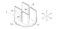
上記液口栓1の筒部12内には、防沫体2が挿入されて取り付けられる。防沫体2は、樹脂成製の防沫構造を備えた部品であり、防沫底板21と一対の防沫縦板22,22と防沫天井板23と防沫庇板24と防沫屋根板25とからなる各防沫板部によって構成されている。下端の防沫底板21は、筒部12の内筒に嵌合するほぼ水平な円板状の防沫板であり、図2に示すように、左右方向の両端部分が左右の外側を上方に向けて10°程度傾斜させて形成されている。また、この防沫底板21の左右の両端には爪21a,21aが突設され、防沫体2を筒部12内に挿入したときに係止部12c,12cに係合させることにより、この防沫体2が下方に抜け落ちないように係止することができるようになっている。
A splash-
一対の防沫縦板22,22は、図3に示すように、防沫底板21の上面から立設した垂直な壁板状の防沫板であり、この防沫体2を筒部12内に挿入して取り付けたときに、前後方向に配置された一対の筒部スリット12b,12bの間の空間の左右側を覆うように前後方向に沿って形成されている。また、各防沫縦板22は、前後方向の中央部に形成された縦板スリット22aの間隙を開けて前後方向に2分割されると共に、これら2分割された前方側の壁板部が後方側の壁板部よりも板厚分だけ左側にずれて形成されている。なお、防沫体2は、このように前後方向に沿う防沫縦板22,22を有するので、樹脂成形の金型は前後方向に2分割された抜き型を用いる。ただし、各防沫縦板22の縦板スリット22aを介した前方側と後方側の壁板部が面一で並んでいる場合には、この縦板スリット22aを形成するために左右方向の抜き型をさらに追加する必要がある。そこで、このように各防沫縦板22の前方側と後方側の壁板部を少なくとも板厚分だけ左右にずらして形成することにより、前後方向に2分割された抜き型だけで樹脂成形が可能にしている。
As shown in FIG. 3, the pair of splash-proof
防沫天井板23は、図4に示すように、左右一対の防沫縦板22,22の間(縦板スリット22a,22aの間も含む)の上方を覆うほぼ水平な防沫板であり、図2に示すように、左右方向の中央を棟とした切り妻型の屋根のように10°程度傾斜させている。即ち、この防沫天井板23は、左右方向の中央を境としたこの左右両側部分が左右の外側を下方に向けて10°程度傾斜している。また、この防沫天井板23は、上面の前後左右方向の中央部から上方に向けて支持柱26を突設している。
As shown in FIG. 4, the splash-
防沫庇板24は、図5に示すように、上記防沫天井板23の上方に配置された、筒部12の内筒に嵌合するほぼ水平な円板状の防沫板であり、左右方向の中央部に形成された庇スリット24aの間隙を開けて左右方向に2分割され、上記支持柱26の側面に一体成形や接着等によって繋がり支持されるようになっている。また、図2に示すように、これら2分割された防沫庇板24の左右方向の両端部分は、左右の外側を上方に向けて10°程度傾斜させて形成されている。庇スリット24aは、左右の幅が防沫天井板23よりも十分に狭く形成されている。
As shown in FIG. 5, the splash-
防沫屋根板25は、図1に示すように、上記防沫庇板24の上方に配置された、筒部12の内筒に嵌合するほぼ水平な円板の左右側の端部を切り落とした形状の防沫板であり、この防沫庇板24の庇スリット24aの上方を左右にはみ出して確実に覆うものである。この防沫屋根板25は、上記支持柱26の上端面上に一体成形や接着等によって繋がり支持されるようになっている。また、この防沫屋根板25の上面は、実際には周囲ほど下方に傾斜した曲面によって構成されている。
As shown in FIG. 1, the splash-
液口栓1の筒部12内には、図2に示すように、上端部の奥に円盤状のフィルタ3が挿入され、この下方に上記防沫体2が挿入されて取り付けられる。そして、この液口栓1の筒部12の上端部にリング状のパッキン4を外嵌し、鉛蓄電池の蓋板の注液口にこの筒部12を挿入すると共に、この注液口のねじ孔にねじ部12aを螺着することにより装着される。
As shown in FIG. 2, a disc-like filter 3 is inserted into the back of the upper end portion, and the splash-
上記構成によれば、鉛蓄電池が垂直方向や水平方向の強い振動を受けて電槽の各セル内に充填された電解液が飛沫となって垂直方向や水平方向に飛散した場合に、まず液口栓1の筒部12の下端開口部から浸入しようとする飛沫は、防沫体2の防沫底板21によって遮られる。従って、この飛沫は、前後に飛散する方向成分を有するものだけが、筒部12の筒部スリット12b,12bを通り抜けて、防沫体2の防沫縦板22,22の間の空間に入り込むことになる。しかしながら、このようにして入り込んだ飛沫は、左右に飛散する方向成分を有するものの一部だけしか、縦板スリット22aを通り抜けて防沫縦板22,22の左右側の空間に入り込むことができず、これら防沫縦板22,22や防沫天井板23に遮られた飛沫は、防沫底板21の上面から筒部スリット12b,12bの下端部を通って再びセル内に戻される。また、防沫縦板22,22の左右側の空間に入り込んだ飛沫は、上方に飛散しても防沫庇板24に遮られるので、防沫縦板22,22よりも左右外側の防沫底板21上の傾斜面に沿って再び縦板スリット22a,22aを通りセル内に戻される。そして、防沫庇板24に遮られることなく庇スリット24aを通り抜けてさらに上方に達した飛沫も、防沫屋根板25に遮られて防沫天井板23上に落下し、屋根状の傾斜に沿って下方に流れて再びセル内に戻される。従って、本実施形態の液口栓1を用いると、筒部12内に水平や垂直のあらゆる飛散方向成分を有する電解液の飛沫が浸入しても、防沫体2を通り抜けることができないために、さらに上方のフィルタ3を介し排気孔11bから外部に溢液するおそれがなくなり、振動溢液性能を向上させることができる。
According to the above configuration, when the lead storage battery is subjected to strong vertical or horizontal vibration and the electrolyte filled in each cell of the battery case is splashed and splashed in the vertical or horizontal direction, Splashes entering from the lower end opening of the
しかも、半円状の大きく傾斜した水平防沫板を上下に複数段配置するのではなく、中央部に庇スリット24aを形成した防沫庇板24の上下に僅かな間隔で防沫天井板23と防沫屋根板25を配置するので、液口栓1の筒部12の長さを短くして鉛蓄電池の高エネルギー密度化を図ることができるだけでなく、筒部スリット12b,12bの上端をねじ部12aの付け根までできるだけ高くすることができるようになり、充電により電解液の液位が上昇しても、これらの筒部スリット12b,12bが電解液に完全に浸かるようなこともなくなる。従って、このような液位上昇時にも、セル内で発生したガスは、筒部スリット12b,12bから筒部12内に入り込み防沫体2の各スリット22a,24aを通り抜けて、フィルタ3を介し排気孔11bから確実に外部に排出することができるので、静的溢液性能も向上させることができる。
In addition, the semi-circular large inclined horizontal splash-proof boards are not arranged in a plurality of stages above and below, but the splash-
なお、上記実施形態では、特に筒部12の短いことが要求されるトップフラットタイプの鉛蓄電池について説明したが、頭部11が蓋板の上面から突出する通常の鉛蓄電池の液口栓1にも同様に実施可能である。また、上記実施形態では、液口栓1にフィルタ3を取り付けた場合を示したが、フィルタ3を用いない液口栓1にも同様に実施可能である。
In addition, in the said embodiment, although the top flat type lead acid battery in which the
また、上記実施形態では、防沫体2の上端に防沫屋根板25を配置する場合を示したが、この防沫屋根板25を配置しない場合にも、ほぼ同等の耐溢液性能を確保することはできる。ただし、より一層の耐溢液性能を得るためには、上記実施形態の防沫屋根板25の上方にさらに防沫庇板と防沫屋根板の組を複数段にわたって配置することも可能であり、これらの防沫板はいずれも支持柱26によって支持させることができる。
Moreover, in the said embodiment, although the case where the splash-
また、上記実施形態では、防沫底板21と防沫天井板23と防沫庇板24に10°程度の傾斜を設ける場合を示したが、この傾斜角度は任意であり、傾斜を設けない場合であっても、電解液の飛沫を円滑にセルに戻す機能は多少劣るものの、耐溢液性能については同等のものを得ることができる。
Moreover, in the said embodiment, although the case where the inclination of about 10 degrees was provided in the splash-
また、上記実施形態では、防沫縦板22,22にずれを設ける場合を示したが、防沫体2の成形加工に支障が生じなければ、このようなずれはなくてもよい。さらに、上記実施形態では、液口栓1の筒部12内に防沫体2を挿入することにより各防沫板を配置する場合を示したが、これらの防沫板の配置手段は任意である。
In the above embodiment, although the case where the deviation in the splash-proof
また、上記実施形態では、自動車用の鉛蓄電池について示したが、この蓄電池の用途や種類も上記実施形態に限定されることはない。 Moreover, in the said embodiment, although it showed about the lead acid battery for motor vehicles, the use and kind of this storage battery are not limited to the said embodiment.
上記実施形態で示した液口栓1と従来例の液口栓をそれぞれ鉛蓄電池に用いて振動溢液性能を比較した結果を表1に示す。ここで、電解液の液位は、電槽のアッパーレベルに合わせた。そして、鉛蓄電池には、上下方向と水平方向における電槽の短軸方向と長軸方向にそれぞれ振動を加えた。これらの各振動は、それぞれ10Hzで5分間加え、また、強さを0.5Gから始めて0.5Gずつ上げ、それぞれの強さについて試験した。さらに、溢液の有無を明確にするために、液口栓1はフィルタ3を取り付けない状態で使用した。 Table 1 shows the results of comparison of vibration overflow performance using the liquid spigot 1 shown in the above embodiment and the liquid spigot of the conventional example in a lead storage battery, respectively. Here, the liquid level of the electrolyte was adjusted to the upper level of the battery case. The lead storage battery was subjected to vibrations in the short axis direction and the long axis direction of the battery case in the vertical and horizontal directions, respectively. Each of these vibrations was applied at 10 Hz for 5 minutes, and the strength was tested by starting with 0.5G and increasing by 0.5G. Furthermore, in order to clarify the presence or absence of overflow, the liquid spigot 1 was used without the filter 3 attached.

この比較結果によれば、上下方向の振動に対する耐溢液性能はほぼ同等であるが、水平方向では実施例の液口栓1を用いた場合の方が優れた耐溢液性能を示し、特に電槽の短軸方向の振動を加えた場合には、従来例よりも遥かに高い耐溢液性能を示すことが分かった。 According to this comparison result, the anti-overflow performance against vibration in the vertical direction is almost the same, but in the horizontal direction, the anti-overflow performance is better when the liquid stopper 1 of the embodiment is used. When vibration in the minor axis direction of the battery case was applied, it was found that the overflow resistance performance was much higher than that of the conventional example.
また、上記実施形態で示した液口栓1と従来例の液口栓をそれぞれ鉛蓄電池に用いて静的溢液性能を比較した結果を表2に示す。ここで、電解液の液位は、電槽のアッパーレベルに合わせた場合(UL)と、これより5mm高い場合(UL+5mm)と、これより10mm高い場合(UL+10mm)とを比較した。そして、充電電流も、10Aと20Aと40Aの場合について、それぞれ2時間の充電を行って比較した。 Table 2 shows the result of comparing the static overflow performance using the liquid spigot 1 shown in the above embodiment and the liquid spigot of the conventional example in a lead storage battery. Here, the case where the level of the electrolyte was adjusted to the upper level of the battery case (UL), the case where it was 5 mm higher (UL + 5 mm), and the case where it was 10 mm higher than this (UL + 10 mm) were compared. The charging currents were also compared for 10 A, 20 A, and 40 A by charging for 2 hours.
この比較結果によれば、液位がアッパーレベルよりも10mm高い異常な場合には、いずれも10Aの充電時に溢液が発生したが、それよりも低い液位では、従来例がどちらも溢液を生じたのに対して、実施例の液口栓1を用いた場合には、充電電流を大きくしても溢液が生じないようになることが分かった。 According to this comparison result, in the case where the liquid level was abnormal 10 mm higher than the upper level, overflow occurred at the time of charging at 10A. However, at the liquid level lower than that, both of the conventional examples overflowed. On the other hand, it was found that when the liquid spout 1 of the example was used, overflow did not occur even when the charging current was increased.
1 液口栓
12 筒部
12b 筒部スリット
2 防沫体
21 防沫底板
22 防沫縦板
22a 縦板スリット
23 防沫天井板
24 防沫庇板
24a 庇スリット
25 防沫屋根板
12
Claims (1)
この液口栓の下端部から電池容器内部に突出する筒部における周側壁の前後位置に上下に細長い一対の筒部スリットが形成され、
この液口栓の筒部内に、
この筒部の内筒の下端部を塞ぐ防沫底板と、
この防沫底板上に立設され、前後一対の筒部スリットの間の空間の左右側を覆うように壁板状に前後方向に沿うと共に、この前後方向の中央部に上下の縦板スリットが形成された一対の防沫縦板と、
これら一対の防沫縦板の間の上方を覆う防沫天井板と、
この防沫天井板の上方で筒部の内筒を塞ぐと共に、左右方向の中央部に庇スリットが形成された防沫庇板と
が配置されたことを特徴とする蓄電池。 In a storage battery equipped with a liquid stopper at the liquid inlet,
A pair of long and narrow cylindrical slits are formed at the front and rear positions of the peripheral side wall of the cylindrical portion protruding from the lower end of the liquid stopper into the battery container,
In the tube part of this liquid spout,
A busy fixture anti smear bottom plate lower end portion of the inner cylinder of the cylindrical portion,
This is splash-proof bottom erected on plate, with along the longitudinal direction of the left and right side so as to cover the wall-shaped space between the front and rear of the cylindrical portion slit, the upper and lower vertical plate slit in the central portion of the front-rear direction A pair of splash-proof vertical plates formed;
A splash-proof ceiling board covering the upper part between the pair of splash-proof vertical boards;
Battery to above the splash-proof ceiling plate with closing the inner cylinder of the cylindrical portion, characterized in that the lateral direction of the central portion proof smear eave plate eaves slits are formed is disposed.
Priority Applications (1)
| Application Number | Priority Date | Filing Date | Title |
|---|---|---|---|
| JP2004218854A JP4706201B2 (en) | 2004-07-27 | 2004-07-27 | Storage battery |
Applications Claiming Priority (1)
| Application Number | Priority Date | Filing Date | Title |
|---|---|---|---|
| JP2004218854A JP4706201B2 (en) | 2004-07-27 | 2004-07-27 | Storage battery |
Publications (3)
| Publication Number | Publication Date |
|---|---|
| JP2006040706A JP2006040706A (en) | 2006-02-09 |
| JP2006040706A5 JP2006040706A5 (en) | 2007-08-30 |
| JP4706201B2 true JP4706201B2 (en) | 2011-06-22 |
Family
ID=35905476
Family Applications (1)
| Application Number | Title | Priority Date | Filing Date |
|---|---|---|---|
| JP2004218854A Expired - Fee Related JP4706201B2 (en) | 2004-07-27 | 2004-07-27 | Storage battery |
Country Status (1)
| Country | Link |
|---|---|
| JP (1) | JP4706201B2 (en) |
Families Citing this family (5)
| Publication number | Priority date | Publication date | Assignee | Title |
|---|---|---|---|---|
| JP5148863B2 (en) * | 2006-11-02 | 2013-02-20 | 古河電池株式会社 | Storage battery exhaust structure |
| JP5634094B2 (en) * | 2010-03-29 | 2014-12-03 | 古河電池株式会社 | Liquid cap for lead acid battery |
| WO2012117502A1 (en) * | 2011-02-28 | 2012-09-07 | 株式会社Gsユアサ | Lead storage battery and method for manufacturing same |
| JP5935381B2 (en) * | 2012-02-22 | 2016-06-15 | 株式会社Lixil | Lid and drain trap |
| JP6427707B1 (en) * | 2018-06-29 | 2018-11-21 | 古河電池株式会社 | Lead storage battery |
Citations (8)
| Publication number | Priority date | Publication date | Assignee | Title |
|---|---|---|---|---|
| JPS6059358U (en) * | 1983-09-28 | 1985-04-25 | トヨタ自動車株式会社 | Storage battery liquid plug |
| JPS60115454U (en) * | 1984-01-13 | 1985-08-05 | 日本電池株式会社 | Liquid spout plug for storage battery |
| JPS60147158U (en) * | 1984-03-12 | 1985-09-30 | 日本電池株式会社 | Transparent liquid stopper for storage battery |
| JPH049738A (en) * | 1990-04-27 | 1992-01-14 | Mitsubishi Heavy Ind Ltd | Method for washing fracture |
| JPH10228892A (en) * | 1997-02-13 | 1998-08-25 | Matsushita Electric Ind Co Ltd | Liquid inlet plug for lead-acid battery |
| JP2001250527A (en) * | 2000-03-08 | 2001-09-14 | Shin Kobe Electric Mach Co Ltd | Explosion-proofing plug for battery |
| JP2002313317A (en) * | 2001-04-11 | 2002-10-25 | Matsushita Electric Ind Co Ltd | Liquid plug for use in storage battery and storage battery furnished with liquid plug for storage battery |
| JP2003178749A (en) * | 2001-12-12 | 2003-06-27 | Japan Storage Battery Co Ltd | Liquid port stopper for lead-acid storage battery, and lead-acid storage battery |
-
2004
- 2004-07-27 JP JP2004218854A patent/JP4706201B2/en not_active Expired - Fee Related
Patent Citations (8)
| Publication number | Priority date | Publication date | Assignee | Title |
|---|---|---|---|---|
| JPS6059358U (en) * | 1983-09-28 | 1985-04-25 | トヨタ自動車株式会社 | Storage battery liquid plug |
| JPS60115454U (en) * | 1984-01-13 | 1985-08-05 | 日本電池株式会社 | Liquid spout plug for storage battery |
| JPS60147158U (en) * | 1984-03-12 | 1985-09-30 | 日本電池株式会社 | Transparent liquid stopper for storage battery |
| JPH049738A (en) * | 1990-04-27 | 1992-01-14 | Mitsubishi Heavy Ind Ltd | Method for washing fracture |
| JPH10228892A (en) * | 1997-02-13 | 1998-08-25 | Matsushita Electric Ind Co Ltd | Liquid inlet plug for lead-acid battery |
| JP2001250527A (en) * | 2000-03-08 | 2001-09-14 | Shin Kobe Electric Mach Co Ltd | Explosion-proofing plug for battery |
| JP2002313317A (en) * | 2001-04-11 | 2002-10-25 | Matsushita Electric Ind Co Ltd | Liquid plug for use in storage battery and storage battery furnished with liquid plug for storage battery |
| JP2003178749A (en) * | 2001-12-12 | 2003-06-27 | Japan Storage Battery Co Ltd | Liquid port stopper for lead-acid storage battery, and lead-acid storage battery |
Also Published As
| Publication number | Publication date |
|---|---|
| JP2006040706A (en) | 2006-02-09 |
Similar Documents
| Publication | Publication Date | Title |
|---|---|---|
| JP6103236B2 (en) | Gas-liquid separator | |
| US8877364B2 (en) | Battery pack | |
| US10056650B2 (en) | Lead-acid battery | |
| JP2009159669A (en) | Electrical connection box | |
| US20130265728A1 (en) | Electronic control unit | |
| JP4706201B2 (en) | Storage battery | |
| JP3615895B2 (en) | Liquid cap for lead acid battery | |
| JP5087435B2 (en) | Electrical junction box | |
| JP2006040706A5 (en) | ||
| JP2009209688A (en) | Structure of oil separator | |
| JP2005197148A (en) | Vent plug for lead-acid battery and lead-acid battery | |
| CN208210459U (en) | A kind of mounting structure of on-vehicle control apparatus | |
| JP6697699B2 (en) | Lead acid battery | |
| JP4021284B2 (en) | Fuel tank | |
| JP5360536B2 (en) | Lead acid battery | |
| CN218536581U (en) | Water retaining structure, drainage device and vehicle | |
| JP4258701B2 (en) | Lead acid battery | |
| JP2009197750A (en) | Structure of oil separator | |
| JP2006100126A (en) | Storage battery | |
| JP6364651B2 (en) | Under cover structure | |
| KR101743698B1 (en) | Battery Pack Of Vehicle | |
| JP4174432B2 (en) | Battery plug for storage battery | |
| CN214493191U (en) | Controller box for electric scooter and electric scooter | |
| WO2020021910A1 (en) | Lead storage battery | |
| US7981534B2 (en) | Rechargeable battery with flexibly connected vent plugs |
Legal Events
| Date | Code | Title | Description |
|---|---|---|---|
| A711 | Notification of change in applicant |
Free format text: JAPANESE INTERMEDIATE CODE: A711 Effective date: 20051213 |
|
| RD03 | Notification of appointment of power of attorney |
Free format text: JAPANESE INTERMEDIATE CODE: A7423 Effective date: 20060119 |
|
| A521 | Request for written amendment filed |
Free format text: JAPANESE INTERMEDIATE CODE: A523 Effective date: 20070629 |
|
| A621 | Written request for application examination |
Free format text: JAPANESE INTERMEDIATE CODE: A621 Effective date: 20070629 |
|
| A521 | Request for written amendment filed |
Free format text: JAPANESE INTERMEDIATE CODE: A523 Effective date: 20070921 |
|
| A711 | Notification of change in applicant |
Free format text: JAPANESE INTERMEDIATE CODE: A712 Effective date: 20100507 |
|
| A977 | Report on retrieval |
Free format text: JAPANESE INTERMEDIATE CODE: A971007 Effective date: 20100902 |
|
| TRDD | Decision of grant or rejection written | ||
| A01 | Written decision to grant a patent or to grant a registration (utility model) |
Free format text: JAPANESE INTERMEDIATE CODE: A01 Effective date: 20110215 |
|
| A61 | First payment of annual fees (during grant procedure) |
Free format text: JAPANESE INTERMEDIATE CODE: A61 Effective date: 20110228 |
|
| R150 | Certificate of patent or registration of utility model |
Ref document number: 4706201 Country of ref document: JP Free format text: JAPANESE INTERMEDIATE CODE: R150 |
|
| LAPS | Cancellation because of no payment of annual fees |