JP4701909B2 - refrigerator - Google Patents

refrigerator Download PDF

Info

Publication number
JP4701909B2
JP4701909B2 JP2005228210A JP2005228210A JP4701909B2 JP 4701909 B2 JP4701909 B2 JP 4701909B2 JP 2005228210 A JP2005228210 A JP 2005228210A JP 2005228210 A JP2005228210 A JP 2005228210A JP 4701909 B2 JP4701909 B2 JP 4701909B2
Authority
JP
Japan
Prior art keywords
pipe
refrigerant
compressor
box
heat
Prior art date
Legal status (The legal status is an assumption and is not a legal conclusion. Google has not performed a legal analysis and makes no representation as to the accuracy of the status listed.)
Active
Application number
JP2005228210A
Other languages
Japanese (ja)
Other versions
JP2007040662A (en
Inventor
竜也 川崎
忠弘 川村
晋一 橋本
Current Assignee (The listed assignees may be inaccurate. Google has not performed a legal analysis and makes no representation or warranty as to the accuracy of the list.)
Panasonic Corp
Panasonic Holdings Corp
Original Assignee
Panasonic Corp
Matsushita Electric Industrial Co Ltd
Priority date (The priority date is an assumption and is not a legal conclusion. Google has not performed a legal analysis and makes no representation as to the accuracy of the date listed.)
Filing date
Publication date
Application filed by Panasonic Corp, Matsushita Electric Industrial Co Ltd filed Critical Panasonic Corp
Priority to JP2005228210A priority Critical patent/JP4701909B2/en
Publication of JP2007040662A publication Critical patent/JP2007040662A/en
Application granted granted Critical
Publication of JP4701909B2 publication Critical patent/JP4701909B2/en
Active legal-status Critical Current
Anticipated expiration legal-status Critical

Links

Images

Landscapes

  • Devices That Are Associated With Refrigeration Equipment (AREA)

Description

本発明は、圧縮機を天面後方に載置した冷蔵庫に関するものである。   The present invention relates to a refrigerator in which a compressor is placed behind the top surface.

近年、冷蔵庫は地球環境保護の観点から更なる省エネルギー化が進むとともに、小さく置けて大きく使える、いわば省スペースで大容量、さらにその使い勝手や収納性の向上が求められている。   In recent years, refrigerators have become more energy-saving from the viewpoint of protecting the global environment, and are required to be small and can be used in large quantities, so to speak, space-saving, large capacity, and improved usability and storage.

従来技術には、小さく置けて大きくつかえる冷蔵庫を実現するために、凝縮器としての配管を断熱箱体の内部に配置させることで、収納容積に影響を与えないスペースをうまく活用する形態がある(例えば、特許文献1参照)。   In the prior art, in order to realize a refrigerator that can be placed small and large, a pipe that serves as a condenser is arranged inside the heat insulation box, thereby effectively utilizing the space that does not affect the storage volume ( For example, see Patent Document 1).

図14は、従来の冷蔵庫の縦断面図を示すものであり、図15は、従来の冷蔵庫の斜視図を示すものである。   FIG. 14 is a longitudinal sectional view of a conventional refrigerator, and FIG. 15 is a perspective view of the conventional refrigerator.

図14、図15で示すように、冷蔵庫本体1は外箱2と、内箱3と、これら両者間に充填された発泡断熱材4等で構成され、同本体1の底部に機械室8を設け、同機械室8内に圧縮機9と、同圧縮機9から発生する熱を放熱する送風機10を配設し、機械室8の後面をカバー15により被っていた。   As shown in FIGS. 14 and 15, the refrigerator main body 1 is composed of an outer box 2, an inner box 3, a foam heat insulating material 4 filled between the two, and a machine room 8 is provided at the bottom of the main body 1. The compressor 9 and the blower 10 that dissipates heat generated from the compressor 9 are disposed in the machine room 8, and the rear surface of the machine room 8 is covered with the cover 15.

また、内箱3内背面に冷却器室5を設け、同冷却器室5内に冷気を生成する冷却器6と、生成した冷気を強制循環する送風機7を配設し、圧縮機9の吐出側と冷却器6の入口との間に凝縮器を兼ねた放熱パイプ11、キャピラリチューブを順次直列に接続して構成した高圧側配管を接続し、冷却器6の出口と圧縮機9の吸入側との間に、前記キャピラリチューブを添設するサクションパイプを直列に接続して構成した低圧側配管を接続している。なお、前記凝縮器を兼ねた放熱パイプ11は、冷蔵庫本体1背面の発泡断熱材4の中に埋設されている。   In addition, a cooler chamber 5 is provided on the back of the inner box 3, a cooler 6 that generates cool air in the cooler chamber 5, and a blower 7 that forcibly circulates the generated cool air are disposed, and the discharge of the compressor 9 A high-pressure side pipe constructed by connecting serially a heat-dissipating pipe 11 that also serves as a condenser and a capillary tube is connected between the inlet side of the cooler 6 and the inlet side of the cooler 6. A low-pressure side pipe constituted by connecting in series a suction pipe to which the capillary tube is attached is connected between the two. The heat radiating pipe 11 also serving as the condenser is embedded in the foam heat insulating material 4 on the back of the refrigerator body 1.

図16はその冷凍サイクルを図に表したものであり、圧縮機9、放熱パイプ11、キャピラリチューブ12、冷却器6がサクションパイプ13によって順次連結され環状の閉回路を形成されている。   FIG. 16 illustrates the refrigeration cycle. The compressor 9, the heat radiating pipe 11, the capillary tube 12, and the cooler 6 are sequentially connected by a suction pipe 13 to form an annular closed circuit.

上記構成において、冷却器6を通過した冷媒が圧縮機9において圧縮され、高温、高圧のガス状冷媒となる。このガス状冷媒が放熱パイプ11により放熱し、中温、高圧の液状冷媒となる。続いて、この液状冷媒はキャピラリチューブ12により減圧された後、冷却器6を通過しながら蒸発し、低温、低圧の冷媒ガスとなり、各区画室における熱交換機能を成している。この後、冷媒はガス状態で再び圧縮機9に吸入されることにより冷凍サイクルを完了するよう構成されている。
特開2002−364975号公報
In the above configuration, the refrigerant that has passed through the cooler 6 is compressed by the compressor 9 and becomes a high-temperature, high-pressure gaseous refrigerant. This gaseous refrigerant dissipates heat through the heat radiating pipe 11 and becomes a medium-temperature, high-pressure liquid refrigerant. Subsequently, the liquid refrigerant is depressurized by the capillary tube 12 and then evaporated while passing through the cooler 6 to become a low-temperature and low-pressure refrigerant gas, thereby forming a heat exchange function in each compartment. Thereafter, the refrigerant is sucked into the compressor 9 again in a gas state, thereby completing the refrigeration cycle.
JP 2002-364975 A

しかしながら、上記従来の構成では、圧縮機を収納する機械室8が冷蔵庫本体の底面後方に位置するため、最下段の貯蔵室の収納容積が小さく、また最上段の貯蔵室に手の届かない収納空間ができてしまうので、必ずしも収納性が良いというものではなかった。   However, in the above-described conventional configuration, the machine room 8 that houses the compressor is located behind the bottom of the refrigerator main body, so that the storage volume of the lowermost storage room is small and the uppermost storage room cannot be reached. Since space was created, it was not always good storage.

また、底面後方に設置する圧縮機は、通常設置される背壁との隙間がほとんどない状態になると、圧縮機の排熱がうまくできなくて、非常に熱がこもりやすいという課題を有していた。   In addition, the compressor installed behind the bottom face has a problem that when there is almost no gap with the back wall that is normally installed, the heat exhausted by the compressor cannot be performed well, and the heat is easily trapped. It was.

また、冷蔵庫本体の背面側に凝縮器としての放熱パイプを配置しているので、一般的に冷蔵庫を設置する際に背面側の壁には隙間なく設置されることが多いことから、放熱が阻害され、しいては庫内側へ熱が侵入してくるといった課題を有していた。   In addition, since a heat dissipating pipe as a condenser is arranged on the back side of the refrigerator main body, it is generally installed on the wall on the back side without any gap when installing a refrigerator, so heat dissipation is hindered. Then, there was a problem that heat entered the inside of the warehouse.

本発明は、上記従来の課題を解決するもので、背伸びしても届かない無効スペースである最上段の貯蔵室の天面後方に圧縮機を載置するもので、最下段の貯蔵室の収納容積の増大、収納性を高めるとともに、比較的開放されやすい天面に位置する圧縮機の放熱を促進し、凝縮器としての放熱パイプの放熱を効率よく、かつ合理的に行える冷凍サイクルを形成した冷蔵庫を提供することを目的とする。   The present invention solves the above-described conventional problems, and places a compressor behind the top surface of the uppermost storage chamber, which is an invalid space that does not reach even if it is stretched back, and stores the lowermost storage chamber. Increased volume and storage capacity, and also promoted heat dissipation of the compressor located on the top, which is relatively easy to open, and formed a refrigeration cycle that can efficiently and rationally dissipate heat from the heat dissipation pipe as a condenser. The object is to provide a refrigerator.

断熱箱体と、前記断熱箱体の天面後方に天面よりも一段低く構成された凹部と、前記断熱箱体に備えられた圧縮機と凝縮器と蒸発器と、そのそれぞれを繋ぐ配管とを順に備えて一連の冷媒流路を形成した冷凍サイクルを備えた冷蔵庫において、前記凹部に圧縮機を収納するとともに、前記配管は少なくとも断熱箱体の前面及び側面に配置されるものである。   A heat insulating box, a recessed portion formed one step lower than the top surface behind the top surface of the heat insulating box, a compressor, a condenser and an evaporator provided in the heat insulating box, and pipes connecting the respective In the refrigerator having a refrigeration cycle in which a series of refrigerant flow paths are formed in order, the compressor is housed in the recess, and the piping is disposed at least on the front and side surfaces of the heat insulating box.

本発明の冷蔵庫は、背伸びしても届かない無効スペースである最上段の貯蔵室の天面後方に圧縮機を設置するもので、最下段の貯蔵室の収納容積の増大、収納性を高めるとともに、比較的開放されやすい天面に位置する圧縮機の放熱を促進し、凝縮器としての冷媒配管の放熱を効率よく、かつ合理的に行える冷凍サイクルを形成することができる。   The refrigerator of the present invention has a compressor installed behind the top surface of the uppermost storage room, which is an invalid space that does not reach even if it is stretched back, and increases the storage capacity of the lowermost storage room, improving the storage capacity. Thus, it is possible to form a refrigeration cycle that can promote heat dissipation of the compressor located on the top surface that is relatively easy to open, and can efficiently and rationally dissipate heat from the refrigerant pipe as a condenser.

請求項1に記載の発明は、断熱箱体と、前記断熱箱体の天面後方に天面よりも一段低く構成された凹部と、前記断熱箱体に備えられた圧縮機と凝縮器と蒸発器と、そのそれぞれを繋ぐ配管とを順に備えて一連の冷媒流路を形成した冷凍サイクルを備えた冷蔵庫において、前記凹部に圧縮機を収納するとともに、前記凹部の空間内の空気を循環させるための放熱ファンを前記圧縮機と所定の間隔をとって横並びに配置し、前記配管は少なくとも断熱箱体の前面及び側面に配置され、また前記配管は前記断熱箱体の外箱を形成する前記側面と前記天面に熱伝導性のある放熱促進手段によって前記外箱に貼り付けて固定され、前記圧縮機から吐出した冷媒は、断熱材内の前記天面の配管を通って一方の前記側面の配管を通り、前記前面の配管を通った後、他方の前記側面の配管を通って、前記断熱材外の前記凹部に接続される前記冷媒流路に導かれ、前記側面の配管は前記側面の後方で前記前面よりも前記凹部よりに貼り付けられることにより、背伸びしても届かない無効スペースである最上段の貯蔵室の天面後方に圧縮機を設置するもので、最下段の貯蔵室の収納容積の増大、収納性を高めるとともに、比較的開放されやすい天面に位置する圧縮機の放熱を促進し、凝縮器としての冷媒配管の放熱を効率よく、かつ合理的に行える冷凍サイクルを形成することができる。また、冷媒配管を前面に配置することで、放熱を促進するとともに貯蔵室の冷気により冷却される前面開口の結露を防止するための手段としても利用できる。また、冷媒配管を側面に配置することで、外箱へ熱伝導させて放熱を促進させることができるとともに、断熱箱体の側面の断熱壁は治具などの抜き勾配が存在し、後方側の壁厚が厚くなるので貯蔵室内への熱侵入を抑制できる。 The invention according to claim 1 is a heat insulating box, a recessed portion formed one step lower than the top surface behind the top surface of the heat insulating box, a compressor, a condenser, and evaporation provided in the heat insulating box. A refrigerator having a refrigerator and a refrigeration cycle in which a series of refrigerant flow paths are formed in order and a pipe connecting them, in order to house the compressor in the recess and circulate the air in the space of the recess The heat dissipating fan is disposed side by side with a predetermined distance from the compressor, the pipe is disposed at least on the front surface and the side surface of the heat insulating box, and the pipe forms the outer box of the heat insulating box. The refrigerant discharged from the compressor is attached to one of the side surfaces through a pipe on the top surface in a heat insulating material. Through the pipe and through the front pipe. Then, the other side pipe is led to the refrigerant flow path connected to the recess outside the heat insulating material, and the side pipe is attached to the recess behind the side rather than the front. By being attached , a compressor is installed behind the top surface of the uppermost storage room which is an invalid space that does not reach even if it is stretched, increasing the storage capacity of the lowermost storage room, improving the storage capacity, It is possible to form a refrigeration cycle that can promote heat dissipation of the compressor located on the top surface that is relatively easy to open, and can efficiently and rationally dissipate heat from the refrigerant pipe as a condenser. Moreover, it can utilize as a means for preventing the dew condensation of the front opening cooled by the cool air of a storage chamber by accelerating heat dissipation by arrange | positioning refrigerant | coolant piping in the front. In addition, by arranging the refrigerant piping on the side surface, heat conduction can be promoted to the outer box to promote heat dissipation, and the heat insulating wall on the side surface of the heat insulating box body has a draft angle such as a jig, Since the wall thickness is increased, heat intrusion into the storage chamber can be suppressed.

請求項2に記載の発明は、請求項1に記載の発明において、前記凹部内に配置し、前記圧縮機で圧縮された高温高圧の冷媒の温度を低下させる螺旋状配管の温度低減手段を接続したことにより、放熱ファンが運転している間は常に外気を取り入れ、また小さいスペースで配管の表面積を格段に増加させているので、圧縮機から吐出される高温高圧の冷媒を、断熱箱体内の配管に入る前に所定の温度まで下げることができる。 According to a second aspect of the present invention, in the first aspect of the present invention, the temperature reducing means of the spiral pipe is arranged in the concave portion and reduces the temperature of the high-temperature and high-pressure refrigerant compressed by the compressor. As a result, outside air is always taken in while the radiating fan is in operation, and the surface area of the piping is greatly increased in a small space, so the high-temperature and high-pressure refrigerant discharged from the compressor is The temperature can be lowered to a predetermined temperature before entering the pipe.

請求項3に記載の発明は、請求項1に記載の発明において、前記凝縮器は前記断熱箱体の底面付近に設けられことにより、上下に冷凍サイクルの構成部品を分割することで、圧縮機及び凝縮器が配置される収納空間の構成部品が減少し、風路が簡素化されるので、風量の増加による放熱能力の促進が可能となる。また、それぞれの収納空間をコンパクトにすることができるので、結果的に貯蔵室の収納容積の増大につながり収納性を高めることが可能となる。 According to a third aspect of the present invention, in the first aspect of the present invention, the condenser is provided near the bottom surface of the heat insulating box, so that the components of the refrigeration cycle are divided into upper and lower parts, thereby compressing the compressor. And the components of the storage space in which the condenser is arranged are reduced, and the air path is simplified, so that it is possible to promote the heat dissipating ability by increasing the air volume. Moreover, since each storage space can be made compact, the storage capacity of the storage chamber is increased as a result, and the storage performance can be improved.

請求項4に記載の発明は、請求項1から3のいずれか一項に記載の発明において、前記蒸発器に付着した霜を除霜する除霜装置と、溶けた霜を貯留するための蒸発皿とを備え、前記凝縮器の一部を前記蒸発皿の内部を経由するよう配置されたものであり、圧縮機という熱源のない底面で放熱する凝縮器の一部を蒸発皿内の水温を上昇させる熱源として利用することができ蒸発能力を向上できるとともに、凝縮器を除霜した比較的低温の水で冷却することができるので、放熱を促進できるメリットも兼ね備える。   The invention according to claim 4 is the invention according to any one of claims 1 to 3, wherein a defrosting device for defrosting the frost attached to the evaporator and evaporation for storing the melted frost. And a part of the condenser is arranged so as to pass through the inside of the evaporating dish, and the temperature of the water in the evaporating dish is adjusted to a part of the condenser that radiates heat at the bottom surface without a heat source called a compressor. It can be used as a heat source to be raised, evaporating ability can be improved, and the condenser can be cooled with defrosted water having relatively low temperature, so that it has the merit of promoting heat dissipation.

請求項5に記載の発明は、請求項3に記載の発明において、前記圧縮機と前記凝縮器を繋ぐ配管は、前記断熱箱体の側面に配置され、かつ外箱と内箱の間に配置されることにより、圧縮機と凝縮器を繋ぐ配管として利用することができ、かつ外箱へ熱伝導させて放熱することができる。   The invention according to claim 5 is the invention according to claim 3, wherein the pipe connecting the compressor and the condenser is disposed on a side surface of the heat insulating box and is disposed between the outer box and the inner box. By doing so, it can be used as piping connecting the compressor and the condenser, and can be dissipated by conducting heat to the outer box.

請求項6に記載の発明は、請求項3に記載の発明において、前記圧縮機と前記凝縮器を繋ぐ配管は、前記断熱箱体の背面に配置され、かつ外箱背板と内箱との間に配置されることにより、背面を構成する外箱の内側表面に予め配管を貼り付けておき、背面と配管と一体化しておくことができ、この場合凹部50との緩衝もなく簡単にはめ込むことができるので、作業性を飛躍的に向上できる。   The invention according to claim 6 is the invention according to claim 3, wherein the pipe connecting the compressor and the condenser is disposed on the back surface of the heat insulating box, and the outer box back plate and the inner box are connected to each other. By being arranged in between, piping can be attached in advance to the inner surface of the outer box that constitutes the back surface, and can be integrated with the back surface and piping. Therefore, workability can be dramatically improved.

請求項に記載の発明は、請求項1からのいずれか一項に記載の発明において、前記配管は、少なくとも圧縮機から吐出された冷媒が凝縮器に至るまでを繋ぐ第一冷媒配管と、凝縮器と減圧器を繋ぐ第二冷媒配管とで構成され、前記第一冷媒配管と第二冷媒配管は前記断熱箱体の外箱と内箱との間に配置され、前記第一冷媒配管の入口側と前記第二冷媒配管の出口側は、前記凹部内にあることにより、凹部を形成する部品を外箱に取り付ける際に配管が同じ方向から突出しているので、一定方向で挿入することで配管の傷付防止や作業バラツキを防止できる。また凹部内での配管溶接箇所を増加させることができるので、作業性を向上できる。 The invention according to claim 7 is the invention according to any one of claims 1 to 6 , wherein the pipe is connected to a first refrigerant pipe connecting at least a refrigerant discharged from the compressor to the condenser. A second refrigerant pipe connecting the condenser and the decompressor, wherein the first refrigerant pipe and the second refrigerant pipe are disposed between the outer box and the inner box of the heat insulating box, and the first refrigerant pipe The inlet side of the second refrigerant pipe and the outlet side of the second refrigerant pipe are in the recess, so that when the part forming the recess is attached to the outer box, the pipe protrudes from the same direction. Can prevent damage to piping and work variations. Moreover, workability can be improved because the number of pipe welds in the recess can be increased.

以下、本発明による冷蔵庫の実施の形態について、図面を参照しながら説明する。なお、この実施の形態によってこの発明が限定されるものではない。   Hereinafter, embodiments of a refrigerator according to the present invention will be described with reference to the drawings. The present invention is not limited to the embodiments.

(実施の形態1)
図1は、本発明の実施の形態1における冷蔵庫の正面図であり、図2は図1のA−A線断面図であり、図3は同実施の形態における冷蔵庫の冷媒配管構成を示す図であり、図4は同実施の形態における冷蔵庫の高圧配管の配置構成を示す図であり、図5は同実施の形態における冷蔵庫の冷媒配管構成を示す図であり、図6は同実施の形態における冷蔵庫の断熱箱体の凹部正面図であり、図7は同実施の形態における冷蔵庫の断熱箱体の凹部上面図であり、図8は同実施の形態における冷蔵庫の断熱箱体の底面分解構成図であり、図9は同実施の形態における冷蔵庫の断熱箱体の背面構成図であり、図10は同実施の形態における冷蔵庫の断熱箱体の凹部構成図を示すものである。
(Embodiment 1)
1 is a front view of a refrigerator according to Embodiment 1 of the present invention, FIG. 2 is a cross-sectional view taken along line AA of FIG. 1, and FIG. 3 is a diagram showing a refrigerant piping configuration of the refrigerator according to the same embodiment. 4 is a diagram showing the arrangement configuration of the high-pressure piping of the refrigerator in the embodiment, FIG. 5 is a diagram showing the refrigerant piping configuration of the refrigerator in the embodiment, and FIG. 6 is the configuration of the embodiment. FIG. 7 is a top view of the recessed portion of the heat insulating box of the refrigerator according to the embodiment, and FIG. 8 is an exploded bottom view of the heat insulating box of the refrigerator according to the same embodiment. FIG. 9 is a rear configuration diagram of the heat insulating box body of the refrigerator in the embodiment, and FIG. 10 is a configuration diagram of a concave portion of the heat insulating box body of the refrigerator in the embodiment.

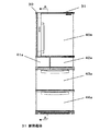
図1から図10において、冷蔵庫本体30は複数の断熱区画に区分されている断熱箱体31と各断熱区画に設けられた扉にて構成されている。断熱箱体31はABSなどの樹脂体を真空成型した内箱32とプリコート鋼板などの金属材料を用いた外箱33とで構成された空間に発泡断熱材34を注入してなる断熱壁を備えている。発泡断熱材34はたとえば硬質ウレタンフォームやフェノールフォームやスチレンフォームなどが用いられる。発泡材としてはハイドロカーボン系のシクロペンタンを用いると、温暖化防止の観点でさらによい。   In FIG. 1 to FIG. 10, the refrigerator main body 30 includes a heat insulating box 31 that is divided into a plurality of heat insulating sections and a door provided in each heat insulating section. The heat insulating box 31 includes a heat insulating wall formed by injecting a foam heat insulating material 34 into a space formed by an inner box 32 formed by vacuum molding a resin body such as ABS and an outer box 33 using a metal material such as a pre-coated steel plate. ing. For example, rigid urethane foam, phenol foam, styrene foam, or the like is used as the foam heat insulating material 34. Use of hydrocarbon-based cyclopentane as the foaming material is better from the viewpoint of preventing global warming.

断熱箱体31は、複数の貯蔵室を形成し、上から冷蔵室40、製氷室41、切替室42、野菜室43、冷凍室44の構成となっていて、各貯蔵室を区画する複数の仕切壁45を備え上から45a、45b、45c、45dである。例えば、仕切壁45dは断熱された壁であり、野菜室43と冷凍室44を区画するものである。各断熱区画の前面開口は各仕切壁と断熱箱体31の前面の縁部101により区画され、それぞれの前面開口には断熱扉が図示しないガスケットを介して設けられる。上から冷蔵室扉40a、製氷室扉41a、切替室扉42a、野菜室扉43a、冷凍室扉44aである。   The heat insulation box 31 forms a plurality of storage chambers, and has a structure of a refrigeration chamber 40, an ice making chamber 41, a switching chamber 42, a vegetable chamber 43, and a freezing chamber 44 from above, and a plurality of compartments dividing each storage chamber. A partition wall 45 is provided, and 45a, 45b, 45c, and 45d are provided from the top. For example, the partition wall 45 d is a thermally insulated wall and partitions the vegetable compartment 43 and the freezing compartment 44. A front opening of each heat insulating section is partitioned by each partition wall and a front edge portion 101 of the heat insulating box 31, and a heat insulating door is provided in each front opening via a gasket (not shown). From the top, the refrigerator door 40a, the ice making door 41a, the switching chamber door 42a, the vegetable compartment door 43a, and the freezer compartment door 44a.

次に、断熱箱体31の各貯蔵室について説明する。   Next, each storage chamber of the heat insulation box 31 will be described.

冷蔵室40は冷蔵保存のために凍らない温度を下限に通常1〜5℃で設定されている。貯蔵室内は上方を圧縮機52を収納するための凹部50が突出して形成され、食品などを整理して収納するための複数の棚70を設け、冷蔵室扉40aの内側にはペットボトルなどの飲料を収納できる複数のポケット71を設けている。最下段には肉魚などの保鮮性向上のための貯蔵ケース72を設け比較的低めの温度、たとえば−3〜1℃で設定されている。   The refrigerator compartment 40 is normally set at 1 to 5 ° C. with the temperature not frozen for refrigerated storage as the lower limit. A concave portion 50 for storing the compressor 52 projects upward from the storage chamber, and a plurality of shelves 70 for organizing and storing food and the like are provided. Inside the refrigerator compartment door 40a, a plastic bottle or the like is provided. A plurality of pockets 71 for storing beverages are provided. A storage case 72 for improving the freshness of meat fish or the like is provided at the lowest level, and is set at a relatively low temperature, for example, -3 to 1 ° C.

製氷室41は、氷を生成して貯留するために通常−22〜−18℃で設定される。庫内は氷を生成するための製氷皿を備えた製氷機構73を設けていて、出来た氷を貯留する貯氷容器74を収容し、レール(図示せず)などで手前に引き出せるよう構成されている。   The ice making chamber 41 is normally set at −22 to −18 ° C. to generate and store ice. The inside of the refrigerator is provided with an ice making mechanism 73 having an ice making tray for generating ice, and is configured to accommodate an ice storage container 74 for storing the produced ice and to be pulled out by a rail (not shown) or the like. Yes.

切替室42は、例えば約3℃に設定された冷蔵室、約1℃に設定されたチルド室、約−1℃から約−3℃に設定されたパーシャル室、約−7℃に設定されたソフト冷凍室、約−18℃に設定された冷凍室として切り替えて利用される。   The switching chamber 42 is set to, for example, a refrigerated chamber set at about 3 ° C, a chilled chamber set at about 1 ° C, a partial chamber set at about -1 ° C to about -3 ° C, and about -7 ° C. It is used by switching as a soft freezer, a freezer set at about -18 ° C.

野菜室43は、冷蔵室40と同等もしくは若干高い温度設定の2℃〜7℃とすることが一般的で、低温にすれほど葉野菜の鮮度を長期間維持することが可能である。庫内は野菜などの食品を整理して収納できる野菜室容器75を収容し、レール(図示せず)などで手前に引き出せるよう構成されている。   The vegetable room 43 is generally set to 2 ° C. to 7 ° C., which is the same as or slightly higher than the temperature of the refrigerated room 40, and the freshness of the leafy vegetables can be maintained for a long time as the temperature is lowered. The inside of the cabinet is configured to accommodate a vegetable compartment container 75 that can organize and store food such as vegetables, and can be pulled out to the front with a rail (not shown).

冷凍室44は、冷凍保存のために通常−22〜−18℃で設定されているが、冷凍保存状態の向上のために、たとえば−30や−25℃の低温で設定されることもある。庫内は食品を整理して収納できる冷凍室容器76を収容し、レール(図示せず)などで手前に引き出せるよう構成されている。   The freezer compartment 44 is normally set at −22 to −18 ° C. for frozen storage, but may be set at a low temperature of −30 or −25 ° C., for example, to improve the frozen storage state. The inside of the cabinet accommodates a freezer compartment 76 that can organize and store foods, and is configured to be pulled out by a rail (not shown) or the like.

野菜室43と冷凍室44の背面に冷却室80が設けられ、冷却室80は断熱性を有する仕切壁45eで野菜室43及び冷凍室44を仕切っている。また、野菜室43と冷凍室44は断熱性を有する仕切壁45dで仕切られている。   A cooling chamber 80 is provided on the back of the vegetable compartment 43 and the freezing compartment 44, and the cooling compartment 80 partitions the vegetable compartment 43 and the freezing compartment 44 by a partition wall 45e having heat insulation properties. The vegetable compartment 43 and the freezer compartment 44 are partitioned by a partition wall 45d having heat insulation properties.

冷却室80には、庫内の空気を熱交換させて冷気に変換する蒸発器83と、各貯蔵室に冷気を送るための冷却ファン84をその上方に位置させ、冷却時に蒸発器83に付着する霜を除霜するためのヒータなどで構成された除霜装置85が備えられている。また、除霜された水を貯留するための蒸発皿86は、断熱箱体31の底面に配置されるよう構成されている。   The cooling chamber 80 is provided with an evaporator 83 for exchanging heat in the cabinet to convert it into cold air, and a cooling fan 84 for sending the cold air to each storage chamber, and is attached to the evaporator 83 during cooling. A defrosting device 85 configured with a heater or the like for defrosting the frost is provided. The evaporating dish 86 for storing defrosted water is configured to be disposed on the bottom surface of the heat insulating box 31.

このような冷蔵庫には、図3のように冷凍サイクルが設けられ、圧縮機52内に封入された冷媒が冷凍サイクルを循環するよう構成される。以下、その冷凍サイクルについて説明する。   Such a refrigerator is provided with a refrigeration cycle as shown in FIG. 3, and is configured such that the refrigerant sealed in the compressor 52 circulates in the refrigeration cycle. Hereinafter, the refrigeration cycle will be described.

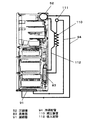
冷凍サイクルは、その全てが密閉空間で構成され、封入された冷媒を圧縮し冷凍サイクルへ高温高圧の冷媒を送り出す圧縮機52、冷媒を放熱し中温高圧に凝縮液化させる凝縮器91、液化冷媒を減圧させる減圧装置110、冷媒を蒸発させて冷熱を発生させる蒸発器83などから構成されて、それぞれが冷媒配管94により接続されている。   The refrigeration cycle is entirely composed of a sealed space, a compressor 52 that compresses the enclosed refrigerant and sends high-temperature and high-pressure refrigerant to the refrigeration cycle, a condenser 91 that dissipates the refrigerant and condenses and liquefies it to medium temperature and high pressure, and a liquefied refrigerant. A decompression device 110 that decompresses, an evaporator 83 that evaporates the refrigerant to generate cold, and the like are connected to each other by a refrigerant pipe 94.

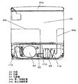
ここで圧縮機52は、断熱箱体31の天面部に背面側を一段低い段差状に窪ませた凹部50に載置される。凹部50は外箱33によって形成された左右壁で囲われていて、断熱箱体31の上方及び背方を開口するよう構成され、その開口はカバー95で覆われている。また、凹部50の空間内の空気を循環させるための放熱ファン96を圧縮機52と所定の間隔をとって、その側方へ横並びにして載置し、圧縮機52に風を当てるような流れで循環し放熱を促進するよう配置されている。   Here, the compressor 52 is placed in a concave portion 50 in which the back side is recessed in a stepped shape that is one step lower on the top surface portion of the heat insulating box 31. The recess 50 is surrounded by left and right walls formed by the outer box 33, and is configured to open above and behind the heat insulating box 31, and the opening is covered with a cover 95. Further, a flow in which a heat dissipating fan 96 for circulating air in the space of the recess 50 is placed side by side with a predetermined distance from the compressor 52 and air is applied to the compressor 52. It is arranged so as to circulate and promote heat dissipation.

凝縮器91は、断熱箱体31の底面付近の前方に配置し、後方には除霜された水を貯留するための蒸発皿86を配置構成している。凝縮器91と蒸発皿86の両部品は冷蔵庫本体30の内容積向上のため、高さを抑え小型で高効率なものを採用している。凝縮器91は代表的なものとしてスパラルフィンチューブ方式があり、断熱箱体31の底面に凝縮器ダクト99とともに底面に固定され、凝縮器91の放熱、あるいは蒸発皿86に貯留される水の蒸発を促進するためのファン98を設置している。また、凝縮器91は冷媒の放熱として以外にも、一部蒸発皿86の内部を経由することで蒸発皿86内の水の温度を上昇させるための熱源としての浸漬パイプ97を構成することもできる。   The condenser 91 is arranged in front of the bottom of the heat insulating box 31 and an evaporating dish 86 for storing defrosted water is arranged in the rear. Both the condenser 91 and the evaporating dish 86 are small in size and highly efficient in order to improve the internal volume of the refrigerator main body 30. A typical condenser 91 is a spall fin tube system, which is fixed to the bottom surface of the heat insulating box 31 together with the condenser duct 99 and radiates heat from the condenser 91 or evaporates water stored in the evaporating dish 86. A fan 98 is installed to promote the above. Further, the condenser 91 may constitute an immersion pipe 97 as a heat source for raising the temperature of water in the evaporating dish 86 by partially passing through the inside of the evaporating dish 86 in addition to the heat dissipation of the refrigerant. it can.

蒸発器83は前述したように、最下段の冷凍室44、その上方の野菜室43の後方に跨るように配置されていて、代表的なものではフィン&チューブ式があり、圧縮機52よりも低い位置に配置されることになる。   As described above, the evaporator 83 is arranged so as to straddle the rear of the lowermost freezer compartment 44 and the vegetable compartment 43 above it, and a typical one is a fin and tube type, which is more than the compressor 52. It will be placed in a low position.

次に上述した圧縮機52、凝縮器91、蒸発器83などを接続するための冷媒配管94について説明する。   Next, the refrigerant pipe 94 for connecting the compressor 52, the condenser 91, the evaporator 83, and the like described above will be described.

冷媒配管94は、代表的なものとして加工しやすくかつ安価な銅管を用いることが多く、その他の手段では鉄管やアルミ管などを用いる場合もある。   As the refrigerant pipe 94, a copper pipe that is easy to process and inexpensive is often used as a typical one, and an iron pipe, an aluminum pipe, or the like may be used as other means.

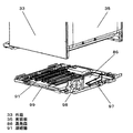
図4に示すように、冷媒配管94は、断熱箱体31の側面と前面に配置されており、第一冷媒配管94a、第二冷媒配管94b、第三冷媒配管94cで構成されている。まず左側面に位置する第一冷媒配管94aは、凹部50の圧縮機52から吐出された冷媒を凝縮器91に送るためのものであり、断熱箱体31の天面から側面を通過して凝縮器91を接続する配管である。また、断熱箱体31の外箱33と内箱32の間に位置し外箱33に当接するよう配置され、その一部はアルミテープなどの放熱促進手段100のように熱伝導性のよい部材にて外箱33に貼り付けるよう固定されている。その後に発泡断熱材34を充填し外箱33に、さらに密着当接されるよう構成している。   As shown in FIG. 4, the refrigerant pipe 94 is disposed on the side surface and the front surface of the heat insulating box 31, and includes a first refrigerant pipe 94 a, a second refrigerant pipe 94 b, and a third refrigerant pipe 94 c. First, the first refrigerant pipe 94 a located on the left side is for sending the refrigerant discharged from the compressor 52 in the recess 50 to the condenser 91, and is condensed through the side surface from the top surface of the heat insulating box 31. This is a pipe for connecting the vessel 91. Further, the heat insulating box 31 is positioned between the outer box 33 and the inner box 32 so as to be in contact with the outer box 33, and a part thereof is a member having good thermal conductivity, such as the heat radiation promoting means 100 such as aluminum tape. It is being fixed so that it may affix on the outer box 33. After that, it is configured to be in contact with the outer box 33 by filling with a foam heat insulating material 34.

次に、前面に位置する第二冷媒配管94bは、凝縮器91で放熱した冷媒をさらに放熱させるための配管であり、断熱箱体31の前面開口に側面の前端を折り曲げて成形し、側面と連通してなる縁部101に沿って、その縁部101のほぼ全周に渡って敷設され、縁部101の内箱32側に位置し前面開口側と当接するよう配置される。より縁部101と密着させるために熱伝導性の良い樹脂などを直接注入して固定する方法もある。また、第二冷媒配管94bは断熱箱体31を温度帯の異なる複数の貯蔵室に区画する複数の仕切壁の前方面にも構成し、この場合は前述した縁部101の右側に配設される第二冷媒配管94bを仕切壁の高さ位置で、仕切壁側に曲げ加工を設けて仕切壁の前方のほぼ全幅を通し、縁部101の左側の手前付近にU曲げ部を設けて仕切壁の前方で上下往復するように配設し縁部101の右側へ戻るよう配設する。このように、他の仕切壁も前述と同様に構成することで、縁部101と仕切壁を配設する第ニ冷媒配管94bは断熱箱体31の前面開口を一筆書きで配置構成されることになる。   Next, the second refrigerant pipe 94b located on the front surface is a pipe for further dissipating the refrigerant radiated by the condenser 91. The second refrigerant pipe 94b is formed by bending the front end of the side surface at the front opening of the heat insulating box 31 and forming the side surface. Along the communicating edge portion 101, it is laid over substantially the entire circumference of the edge portion 101, and is positioned on the inner box 32 side of the edge portion 101 so as to be in contact with the front opening side. There is also a method of directly injecting and fixing a resin having good thermal conductivity in order to make it closely contact with the edge portion 101. The second refrigerant pipe 94b is also configured on the front surface of a plurality of partition walls that divide the heat insulating box 31 into a plurality of storage chambers having different temperature zones, and in this case, is disposed on the right side of the edge portion 101 described above. The second refrigerant pipe 94b is bent at the height of the partition wall and is bent on the partition wall side so as to pass through almost the entire width in front of the partition wall. It arrange | positions so that it may reciprocate up and down in front of a wall, and it may arrange | position so that it may return to the right side of the edge part 101. FIG. As described above, the other partition walls are configured in the same manner as described above, so that the second refrigerant pipe 94b in which the edge portion 101 and the partition wall are disposed is configured so that the front opening of the heat insulating box 31 is arranged with a single stroke. become.

一方、右側面に位置する第三冷媒配管94cは、凝縮器91及び第ニ冷媒配管94bで凝縮液化した冷媒を断熱箱体31の右側面から天面を通り、凹部50の天面側に再び戻すためのものであり、前述した第一冷媒配管94aと同じように、アルミテープなどの放熱促進手段100により外箱33の内側表面に貼り付けるよう構成されている。ここで、第一冷媒配管94aと第三冷媒配管94cとの貼り付け位置は、できる限り外箱33の側面後方に貼り付けることが望ましい。なぜなら、通常断熱箱体31の側面の断熱壁は治具などの抜き勾配が存在し、後方側の壁厚が厚くなるので貯蔵室内への熱侵入が少なくなるという利点を有するためである。   On the other hand, the third refrigerant pipe 94c located on the right side again passes the refrigerant condensed and liquefied by the condenser 91 and the second refrigerant pipe 94b from the right side of the heat insulation box 31 to the top side of the recess 50. It is for returning, and is configured to be affixed to the inner surface of the outer box 33 by means of heat radiation promotion means 100 such as aluminum tape, like the first refrigerant pipe 94a described above. Here, it is desirable to attach the first refrigerant pipe 94a and the third refrigerant pipe 94c to the rear side of the outer box 33 as much as possible. This is because the heat insulating wall on the side surface of the normal heat insulating box 31 has a draft angle such as a jig, and the wall thickness on the rear side is increased, so that heat penetration into the storage chamber is reduced.

前述したような冷媒配管94は、図5に示すように、通常、外箱33を形成するプリコート鋼板などの金属材を平板の状態で、側面に位置する第一冷媒配管94a、第三冷媒配管94cを所定の位置に設置し、必要な箇所にアルミテープなどの放熱促進部材100を貼り付けて固定しておき、その後、外箱33を第一冷媒配管94aと第三冷媒配管94cとともに所定の折り曲げ線102で折り曲げて、外箱33の天面、側面を構成する方法をとる。なお、前面に位置する第二冷媒配管94bも前述と同様にして折り曲げて構成する方法もある。   As shown in FIG. 5, the refrigerant pipe 94 as described above is usually a first refrigerant pipe 94 a and a third refrigerant pipe located on the side surfaces of a metal material such as a precoated steel plate forming the outer box 33 in a flat plate state. 94c is installed at a predetermined position, and a heat radiation promoting member 100 such as an aluminum tape is pasted and fixed at a required position, and then the outer box 33 is fixed together with the first refrigerant pipe 94a and the third refrigerant pipe 94c. A method is adopted in which the top and side surfaces of the outer box 33 are formed by folding along a folding line 102. There is also a method in which the second refrigerant pipe 94b located on the front surface is also bent in the same manner as described above.

減圧装置110は、放熱して凝縮液化された高圧の冷媒を、減圧して蒸発器83へ送るためのものであり、断熱箱体31の背面板35と内箱32の背面との間でどちらにも当接しないよう発泡断熱材34に覆われるよう配置構成される。減圧装置110は、一般的に管径の小さいものを使用することが多く冷蔵庫では約0.5mm〜1mm(管内径)を使用することが多い。その他に冷媒の流量を自由に制御できる冷媒流量制御弁や、膨張弁を用いて減圧しても構わない。また、減圧装置110に至る前に、冷媒配管94内のゴミや金属粉等を圧縮機52へ戻さないための図示しないフィルターや、システム内の水分を吸着する図示しない吸着部材などを備えたドライヤ111を冷凍システム内に設け、凹部50に収納され圧縮機52の風上側である放熱ファン96周辺に配置構成している。   The decompression device 110 is for depressurizing and sending the high-pressure refrigerant that has been condensed and liquefied by heat dissipation to the evaporator 83, and between the back plate 35 of the heat insulation box 31 and the back of the inner box 32. Also, it is arranged and configured to be covered with the foam heat insulating material 34 so as not to come into contact with. The decompression device 110 generally uses a small tube diameter, and a refrigerator often uses about 0.5 mm to 1 mm (tube inner diameter). In addition, the pressure may be reduced using a refrigerant flow rate control valve or an expansion valve that can freely control the flow rate of the refrigerant. Further, before reaching the decompression device 110, a dryer provided with a filter (not shown) for preventing dust and metal powder in the refrigerant pipe 94 from returning to the compressor 52, a suction member (not shown) for adsorbing moisture in the system, and the like. 111 is provided in the refrigeration system and is arranged around the heat radiating fan 96 which is housed in the recess 50 and is on the windward side of the compressor 52.

吸入配管112は、蒸発器83で気化した冷媒を圧縮機52へと戻すためのものであり、断熱箱体31の背面板35と、内箱32背面との間に配置され、背面板35と内箱32の背面とのどちらにも当接しないよう発泡断熱材34に覆われるよう構成される。   The suction pipe 112 is for returning the refrigerant vaporized by the evaporator 83 to the compressor 52, and is arranged between the back plate 35 of the heat insulating box 31 and the back of the inner box 32, It is configured to be covered with the foam heat insulating material 34 so as not to contact either the back surface of the inner box 32.

また、吐出配管113は、凹部50内に圧縮機52と第一冷媒配管94aとを接続するものであり、吐出配管113は通常直線的に最短距離でもって配置されるが、今回は圧縮機52で圧縮された高温高圧の冷媒を、第一冷媒配管94aへ直接入れずに所定の温度まで低下させるため、螺旋状に巻付けるなどして所定の長さを取る温度低減手段114を設けているとともに、圧縮機52よりも風上側に配置構成されている。   Further, the discharge pipe 113 connects the compressor 52 and the first refrigerant pipe 94a in the recess 50, and the discharge pipe 113 is usually arranged with the shortest distance in a straight line. In order to reduce the high-temperature and high-pressure refrigerant compressed in step 1 to a predetermined temperature without directly entering the first refrigerant pipe 94a, a temperature reduction means 114 is provided which takes a predetermined length by, for example, spirally winding. At the same time, it is arranged on the windward side of the compressor 52.

以上のように構成された冷蔵庫について、以下その作用について説明する。   About the refrigerator comprised as mentioned above, the effect | action is demonstrated below.

まず、圧縮機52を断熱箱体31の天面後方の凹部50に載置して最下方の貯蔵室である冷凍室44の後方領域には配置せず、冷却室80を冷凍室44とその上方の野菜室43の背面に配置し、蒸発器83と冷却ファン84を概ね冷凍室44と野菜室43の高さ範囲内で設け、蒸発器83を高さ方向に延長させ奥行き寸法を短縮することにより、冷却室80の厚みを薄くして庫内容積として寄与しない無効スペースを減少し、野菜室43、冷凍室44の収納容積を増大し収納性を高めることができる。また断熱箱体31の天面後方の凹部50は使用者が手の届き難い、いわば無効スペースに近い空間であったため、その箇所に圧縮機52を位置させることは極めて冷蔵庫本体30の内容積をうまく活用できることになる。さらに野菜室43、冷凍室44を引出し式の貯蔵室としているので、野菜室容器75、冷凍室容器76の奥に収納された食品なども楽に出し入れできて使い勝手の向上も図れる。   First, the compressor 52 is placed in the concave portion 50 at the rear of the top surface of the heat insulating box 31 and is not disposed in the rear region of the freezing chamber 44 which is the lowermost storage chamber. Arranged on the back of the upper vegetable compartment 43, the evaporator 83 and the cooling fan 84 are provided approximately within the height range of the freezer compartment 44 and the vegetable compartment 43, and the evaporator 83 is extended in the height direction to reduce the depth dimension. Thus, the thickness of the cooling chamber 80 can be reduced to reduce the ineffective space that does not contribute to the internal volume, and the storage capacity of the vegetable room 43 and the freezing room 44 can be increased to improve the storage capacity. Moreover, since the recessed part 50 of the back | upper surface of the heat insulation box 31 was difficult for the user to reach, so to speak, it was a space close to an invalid space, so positioning the compressor 52 at that location would greatly increase the internal volume of the refrigerator body 30. It can be used well. Furthermore, since the vegetable compartment 43 and the freezing compartment 44 are drawer-type storage compartments, food stored in the back of the vegetable compartment container 75 and the freezing compartment container 76 can be easily put in and out, and the usability can be improved.

ただし、断熱箱体の天面後方の凹部50を極力小さく形成し、最上方の冷蔵室40の庫内側への突出代を極力小さくしなければ、冷蔵室40の庫内が視覚的にも圧迫感や閉塞感を感じるものになってしまう。   However, if the recess 50 on the rear side of the top surface of the heat insulation box is formed as small as possible and the protrusion of the uppermost refrigerating chamber 40 to the inner side is not minimized, the inside of the refrigerating chamber 40 is visually compressed. The feeling of feeling and obstruction will be felt.

したがって、冷蔵庫本体30の底面に冷凍サイクルの凝縮器91を配置して、凹部50には圧縮機52を冷却する放熱ファンのみを配置し放熱を促進することが必要となり、この場合、凹部50の容積及び排熱風路を小さく形成し、冷蔵室40への庫内への突出代を抑制することができる。   Therefore, it is necessary to arrange the condenser 91 of the refrigeration cycle on the bottom surface of the refrigerator main body 30 and arrange only the heat dissipating fan for cooling the compressor 52 in the recess 50 to promote heat dissipation. The volume and the exhaust heat air passage can be formed small, and the protruding margin into the refrigerator compartment 40 can be suppressed.

特に、近年、使用者の使用頻度や鮮度管理のしやすさ、人間工学的な使い勝手の観点などから、使用頻度の最も高い冷蔵室40を使用者の前面で見開いて出し入れできる上段位置に、重量物の出し入れもありかつ健康志向で日常的に鮮度管理もしたい野菜室43を使いやすい中段に、そして長期間出し入れしないストック品などもありかつ取り扱い時の落下などへの配慮も必要な冷凍室44を最下段にレイアウトした冷蔵庫が主流になっているが、このレイアウトにおいて圧縮機52を含めた機械室の配置で最下段の冷凍室44の収納容量を十分に確保できないのが欠点であったが、本実施の形態によると最下段の冷凍室44の奥行きを野菜室43と同様に拡大することができて、しかも室内の空間形状も複雑な形状とならず大きめの収納物も合理的に収納できて収納性を高めることができ、長期冷凍保存のストック食品のほか弁当や惣菜用など短期冷凍保存のフロー食品の増加による冷凍食品の利用頻度の増加にも十分に対応できる利便性の高い冷蔵庫を提供できる。   In particular, in recent years, from the viewpoint of the user's usage frequency, ease of freshness management, ergonomic ease of use, etc., the refrigerator compartment 40 with the highest frequency of use is placed in the upper position where it can be opened and removed in front of the user. The vegetable room 43, where you can put in and out things and want to maintain freshness on a daily basis, is easy to use, and there is a freezer room 44 that has stock items that you don't put in and out for a long time, and you need to consider dropping during handling. However, it is a disadvantage that the storage capacity of the lowermost freezer compartment 44 cannot be secured with the layout of the machine room including the compressor 52 in this layout. According to the present embodiment, the depth of the lowermost freezer compartment 44 can be expanded in the same manner as the vegetable compartment 43, and the indoor space shape does not become complicated and is a large storage item. Convenient enough to handle the increase in the frequency of use of frozen foods due to the increase in the number of flow foods for short-term frozen storage such as lunch boxes and prepared foods in addition to stock foods for long-term frozen storage, as well as rational storage and enhanced storage. A highly functional refrigerator can be provided.

これらの収納容量,収納性に関わる効果は、冷凍室44,野菜室43が引き出し式の貯蔵室でなくても享受できるものであるが、引き出し式の貯蔵室であればさらにその効用は大きい。すなわち、引き出し用のレール長さをほぼ同等のものとすることにより冷凍室容器76の引き出し代と野菜室容器75の引き出し代をほぼ同等に合わせることが可能となり、使用者が日常、両室の収納容器を引き出して引き出し代が異なることに対して違和感を覚えることがなく、また、引き出された収納容器の形状も双方がほぼ直方体状のシンプルな形状で揃えることができ、引き出したときの統一感があって冷蔵庫の商品品位としても高いものとなる。   The effects relating to the storage capacity and storage performance can be enjoyed even if the freezer compartment 44 and the vegetable compartment 43 are not drawer-type storage rooms, but the utility is even greater if they are drawer-type storage rooms. That is, by making the drawer rail lengths substantially the same, it becomes possible to match the drawer allowance of the freezer compartment 76 and the drawer allowance of the vegetable compartment container 75 almost equally, and the user can adjust the drawers of both rooms daily. There is no sense of incongruity when the storage container is pulled out and the pulling out is different, and the shape of the pulled out storage container can be aligned in a simple shape that is almost a rectangular parallelepiped. There is a feeling and it becomes high as the product quality of the refrigerator.

次に、冷凍サイクルの動作に関しては、庫内の設定された温度に応じて制御基板(図示せず)からの信号により冷凍サイクルが動作して冷却運転が行なわれる。圧縮機52の動作により吐出された高温高圧の冷媒は、凹部50内に配置された吐出配管113、第一冷媒配管94aを経由し、凝縮器91及び第二冷媒配管94bにて放熱して中温高圧の冷媒に凝縮液化し、第三冷媒配管94cを経由して減圧装置92により減圧されて低温低圧の液冷媒となって蒸発器83に至る。   Next, regarding the operation of the refrigeration cycle, the refrigeration cycle is operated by a signal from a control board (not shown) according to the temperature set in the warehouse, and the cooling operation is performed. The high-temperature and high-pressure refrigerant discharged by the operation of the compressor 52 radiates heat in the condenser 91 and the second refrigerant pipe 94b via the discharge pipe 113 and the first refrigerant pipe 94a disposed in the concave portion 50, and has a medium temperature. The liquid is condensed and liquefied into a high-pressure refrigerant, and is decompressed by the decompression device 92 via the third refrigerant pipe 94 c to reach the evaporator 83 as a low-temperature and low-pressure liquid refrigerant.

冷却ファン84の動作により、各貯蔵室内の空気と熱交換されて蒸発器83内の冷媒は蒸発気化し、低温の冷気を図示しないダンパ装置などで供給制御することで、各貯蔵室の設定された所定の温度を維持できるよう冷却を行う。蒸発器83を出た冷媒は吸入配管112を経て圧縮機52へと吸い込まれる。   By the operation of the cooling fan 84, heat is exchanged with the air in each storage chamber, the refrigerant in the evaporator 83 evaporates, and supply of low-temperature cold air is controlled by a damper device (not shown) to set each storage chamber. Cooling is performed so that the predetermined temperature can be maintained. The refrigerant exiting the evaporator 83 is sucked into the compressor 52 through the suction pipe 112.

ここで、圧縮機52は上方の凹部50に、凝縮器91は底面に配置し、それぞれを放熱するための放熱ファン96とファン98を設けることで、従来、主であった凝縮器を冷却した空気でもって圧縮機を冷却するという直列配置から、圧縮機52及び凝縮器91を放熱するための風路を上下に分割し並列配置し、風路構成を簡略化することで風路の小型化を可能とし、かつ放熱能力を向上できるので凝縮器91を小型化し冷蔵庫本体30の無効スペースを減少させることができる。   Here, the compressor 52 is disposed in the upper concave portion 50, the condenser 91 is disposed on the bottom surface, and a heat dissipating fan 96 and a fan 98 for dissipating the heat are provided to cool the conventional main condenser. From the serial arrangement in which the compressor is cooled with air, the air passage for radiating heat from the compressor 52 and the condenser 91 is divided into upper and lower parts, arranged in parallel, and the air passage configuration is simplified to reduce the size of the air passage. In addition, since the heat dissipation capability can be improved, the condenser 91 can be downsized and the ineffective space of the refrigerator main body 30 can be reduced.

本実施の形態の圧縮機52は、凹部50をできる限り小さく形成することで、冷蔵室40への前方及び下方への突出を抑え、最上段の棚70とほぼ同一の高さに抑えることで、手の届く位置の収納容積を減少させることなく、実際に使用する際に何ら問題なく収納性を高めることができ、かつ、凹部50を幅方向に細長く形成し、放熱ファン96を幅方向に風が流れるよう構成することで、一つの四角い筒状のダクトにすることができ、圧縮機52の放熱に対して効率良く、かつ合理的な風路を構成することができる。   The compressor 52 of the present embodiment is formed by making the concave portion 50 as small as possible, thereby suppressing forward and downward protrusion to the refrigerator compartment 40 and suppressing the height to be substantially the same as that of the uppermost shelf 70. The storage capacity can be improved without any problem in actual use without reducing the storage capacity at a reachable position, and the recess 50 is elongated in the width direction, and the heat radiating fan 96 is formed in the width direction. By configuring so that the wind flows, it is possible to form a single square cylindrical duct, and it is possible to configure an efficient and rational air path for the heat dissipation of the compressor 52.

次に、凝縮器91及び断熱箱体31の底面近傍に関しては、貯蔵室にとって無効スペースともいえる断熱箱体31の底面に凝縮器91を配置し、ファン98でもって外気と熱交換させることで放熱能力を向上させることができる。また、凝縮器91の一部を蒸発皿86内に貯留される水と接触するように経由させる浸漬パイプ97を設けることで、水の温度を上昇させる熱源として、また凝縮器91の一部としての効果を同時に得ることができる。   Next, with respect to the vicinity of the bottom surface of the condenser 91 and the heat insulation box 31, heat is dissipated by disposing the condenser 91 on the bottom surface of the heat insulation box 31, which can be said to be an invalid space for the storage room, and exchanging heat with the outside air by the fan 98. Ability can be improved. Further, by providing a dip pipe 97 through which a part of the condenser 91 is brought into contact with the water stored in the evaporating dish 86, as a heat source for raising the temperature of the water, and as a part of the condenser 91 The effect of can be obtained at the same time.

さらに、凝縮器91を風上側に、蒸発皿86を風下側に配置することで風上側の凝縮器91はファンが運転しているときに常に外気を取り入れ放熱を促進するとともに、その放熱された若干温度の高い乾燥した空気を、風下側の蒸発皿86の表面を通過させることで、前述した浸漬パイプ97で水温を上げることとの相乗効果で飛躍的に蒸発能力を向上できる。   Furthermore, by disposing the condenser 91 on the windward side and the evaporating dish 86 on the leeward side, the windward side condenser 91 always takes in outside air when the fan is operating and promotes heat dissipation, and the heat is dissipated. By allowing the dry air having a slightly high temperature to pass through the surface of the evaporating dish 86 on the leeward side, the evaporating ability can be drastically improved by a synergistic effect with increasing the water temperature by the immersion pipe 97 described above.

次に、本実施の形態の冷媒配管94に関しては、冷媒配管94を断熱箱体31の外箱33と内箱32の間に配置することで、もともと断熱箱体31の貯蔵室内外を断熱する発泡断熱材34の箇所であり、いわば貯蔵室の収納容積に対しての無効スペースを利用して圧縮機52、凝縮器91、蒸発器83とを接続することができるので、庫内の収納容積を減少することなく配管の構成ができる。   Next, regarding the refrigerant pipe 94 of the present embodiment, the refrigerant pipe 94 is disposed between the outer box 33 and the inner box 32 of the heat insulating box 31 to insulate the outside of the storage box of the heat insulating box 31 originally. Since the compressor 52, the condenser 91, and the evaporator 83 can be connected to each other by using an invalid space with respect to the storage volume of the storage chamber, which is the location of the foam heat insulating material 34, the storage volume in the warehouse It is possible to configure the pipe without reducing the flow.

また、第一冷媒配管94aはアルミテープなどの放熱促進手段100を介して外箱33に貼り付けているので、通過する高温高圧の冷媒を外箱33に効率良く熱伝導させ、貯蔵室側は発泡断熱材34を充填しているので熱伝導はしにくく、より外箱33への熱伝導を促進し、効率良くかつ合理的な放熱手段を構成することができる。また、第二冷媒配管94bは前面開口の縁部101の貯蔵室側の前方に取り付けてあるため、上述の第一冷媒配管94aと同様の作用を得ることができる。一方、貯蔵室側からの冷気の熱伝導により縁部101や仕切壁45の前方面は冷やされる傾向にあるが、第二冷媒配管94bを縁部101や仕切壁45の前方面に配置構成することで、その表面温度を高く維持することができるため結露や霜付きを防止することもできる。なお、仕切壁45bのように配管の曲げ加工や配置構成のしにくい箇所などではヒータなどの熱源を用いることで、結露防止の効果はさほど変わらずに構成することも可能である。   In addition, since the first refrigerant pipe 94a is attached to the outer box 33 via the heat radiation promoting means 100 such as aluminum tape, the high-temperature and high-pressure refrigerant passing therethrough is efficiently conducted to the outer box 33. Since the foam heat insulating material 34 is filled, it is difficult to conduct heat, the heat conduction to the outer box 33 is further promoted, and an efficient and rational heat dissipating means can be configured. Moreover, since the 2nd refrigerant | coolant piping 94b is attached ahead of the storage chamber side of the edge 101 of a front opening, the effect | action similar to the above-mentioned 1st refrigerant | coolant piping 94a can be acquired. On the other hand, the front surface of the edge portion 101 and the partition wall 45 tends to be cooled by the heat conduction of the cold air from the storage chamber side, but the second refrigerant pipe 94b is arranged and configured on the front surface of the edge portion 101 and the partition wall 45. As a result, the surface temperature can be kept high, so that condensation and frosting can be prevented. It should be noted that by using a heat source such as a heater in places such as the partition wall 45b where it is difficult to bend or arrange the piping, the effect of preventing condensation can be configured without much change.

また、第二冷媒配管94bと第三冷媒配管94cを接続する箇所を、断熱箱体31の後方側にすれば、第一冷媒配管94aと第三冷媒配管94cは左右対称にすることができ、この場合は部品の共用化とともに作業性の軽減を図ることも可能となる。   Moreover, if the location which connects the 2nd refrigerant | coolant piping 94b and the 3rd refrigerant | coolant piping 94c is made into the back side of the heat insulation box 31, the 1st refrigerant | coolant piping 94a and the 3rd refrigerant | coolant piping 94c can be made bilaterally symmetrical, In this case, it is possible to reduce the workability while sharing parts.

また、冷媒配管94は、外箱33をU曲げする前の平板の状態で所定の位置に設置し、折り曲げて天面及び左右両側面を構成することにより、冷媒配管94を立体的に形成する必要かなく、平面的な部品で構成することができ安価になるメリットと、平面上で外箱に取り付けることができるので、作業性を飛躍的に向上することが可能となる。   Moreover, the refrigerant | coolant piping 94 is installed in a predetermined position in the state of the flat plate before U-bending the outer case 33, is bent, and comprises a top | upper surface and both right and left side surfaces, and forms the refrigerant | coolant piping 94 in three dimensions. It is not necessary, and can be configured with planar parts, so that it can be inexpensive, and can be attached to the outer box on a plane, so that workability can be dramatically improved.

また、凹部50から出入りする第一冷媒配管94aと第三冷媒配管94cを、断熱箱体31の天面側のみにすることで、凹部50を構成する部品を断熱箱体31の後方より前方にはめ込む際に、冷媒配管94を傷つけたり、折ったりせずに設置することができて、嵌め込み作業を効率よく、かつ簡便に行うことができる。また、圧縮機52や吐出配管113やドライヤ111などを接続する際の溶接箇所を近傍に配置することによる冷媒配管94の接続や溶接作業の効率化も図れる。   Further, the first refrigerant pipe 94 a and the third refrigerant pipe 94 c that enter and exit from the recess 50 are only on the top surface side of the heat insulation box 31, so that the components constituting the recess 50 are forward from the rear of the heat insulation box 31. At the time of fitting, the refrigerant pipe 94 can be installed without being damaged or broken, and the fitting operation can be performed efficiently and simply. Further, it is possible to connect the refrigerant pipe 94 and to improve the efficiency of the welding work by arranging the welding location when connecting the compressor 52, the discharge pipe 113, the dryer 111, and the like.

また、本実施の形態では、吐出配管113の配管を螺旋状にした温度低減手段114を設けて、放熱ファン96の吸込み側に設けることで、放熱ファン96が運転している間は常に外気を取り入れ、また小さいスペースで配管の表面積を格段に増加させているので、圧縮機52から吐出される高温高圧の冷媒を、断熱箱体31内の第一冷媒配管94aに入る前に所定の温度まで下げることができる。これにより、仮に使用者が断熱箱体31の天面部に触れたときにでも火傷など高温に対する違和感を持つことがなく、また天面部に荷物を置いた場合でも温度が低いので荷物の変色や腐食することなく安心して使える冷蔵庫を提供できる。また、断熱箱体31の表面温度も同様に低下することから、各貯蔵室内への熱の侵入を抑制でき消費電力量の低減にも繋がる。さらに、螺旋状の温度低減手段114により圧縮機52の回転周波数から吐出配管113の共振点をずらすことで、断熱箱体31への振動伝播を防止することが可能となる。   Further, in the present embodiment, the temperature reducing means 114 in which the piping of the discharge pipe 113 is spirally provided and provided on the suction side of the heat radiating fan 96, so that the outside air is always taken while the heat radiating fan 96 is operating. In addition, since the surface area of the pipe is remarkably increased in a small space, the high-temperature and high-pressure refrigerant discharged from the compressor 52 is brought to a predetermined temperature before entering the first refrigerant pipe 94a in the heat insulating box 31. Can be lowered. As a result, even when the user touches the top surface of the heat insulation box 31, there is no sense of discomfort with high temperatures such as burns, and even when the bag is placed on the top surface, the temperature is low, so the discoloration and corrosion of the bag It can provide a refrigerator that can be used without worry. Moreover, since the surface temperature of the heat insulation box 31 falls similarly, the penetration | invasion of the heat | fever into each storage chamber can be suppressed, and it leads also to the reduction of power consumption. Further, by shifting the resonance point of the discharge pipe 113 from the rotational frequency of the compressor 52 by the spiral temperature reducing means 114, it is possible to prevent vibration propagation to the heat insulating box 31.

次に、減圧装置110と吸入配管112に関しては、キャピラリなどの減圧装置110と吸入配管112は、通常半田などの密着手段によって配管同士が接触するよう構成され、比較的温度の高い減圧装置110と比較的温度の低い吸入配管112を互いに熱交換させている。これは、減圧装置110はさらに温度を低くでき冷媒を確実に液化させ、冷凍能力を向上することができるとともに、吸入配管112は温度を高くすることで確実に気化させ、圧縮機52の吸込圧力を上げて冷媒循環量を増加させることによる、効率の良い冷凍サイクルを構成することができる。また断熱箱体31の背壁内に収納され、発泡断熱材34で覆われて断熱されていることから、蒸発器83で気化した低温の冷媒が配管内を通っている吸入配管112の接触による結露などの心配が無い。   Next, with regard to the decompression device 110 and the suction pipe 112, the decompression device 110 such as a capillary and the suction pipe 112 are usually configured such that the pipes are in contact with each other by close contact means such as solder, and the decompression device 110 having a relatively high temperature. The suction pipes 112 having a relatively low temperature exchange heat with each other. This is because the decompression device 110 can further lower the temperature to reliably liquefy the refrigerant and improve the refrigerating capacity, and the suction pipe 112 can be reliably vaporized by increasing the temperature, and the suction pressure of the compressor 52 An efficient refrigeration cycle can be configured by increasing the amount of refrigerant circulation by increasing the amount of refrigerant. Further, since it is housed in the back wall of the heat insulation box 31 and is covered and insulated by the foam heat insulating material 34, the low temperature refrigerant vaporized by the evaporator 83 is brought into contact with the suction pipe 112 passing through the pipe. There is no worry about condensation.

このことからも、減圧装置110の入口側になるドライヤ111は上方凹部50に配設する方が良く、仮に下方に配設すると減圧装置110と吸入配管112が熱交換をし難い構成になってしまうからである。また、ドライヤ111は凹部50内で圧縮機52よりも風上側におくことで、放熱された高圧冷媒を常に外気に接触させることができ、もし仮に圧縮機52の風下側に位置させると放熱され液化した冷媒が再び加熱されて気化し、冷凍サイクルに不具合をきたす恐れがあるのに対し問題なく液化した冷媒を蒸発器83に供給することが可能となる。   For this reason as well, it is better to dispose the dryer 111 on the inlet side of the decompression device 110 in the upper recess 50. If the dryer 111 is disposed below, the decompression device 110 and the suction pipe 112 are difficult to exchange heat. Because it ends up. Further, the dryer 111 is placed on the windward side of the compressor 52 in the recess 50, so that the radiated high-pressure refrigerant can always be brought into contact with the outside air. If the dryer 111 is positioned on the leeward side of the compressor 52, the heat is radiated. While the liquefied refrigerant is heated again and vaporizes, there is a possibility that the refrigeration cycle may be malfunctioned. However, the liquefied refrigerant can be supplied to the evaporator 83 without any problem.

このように、圧縮機52が冷凍室44の後方に存在せず、断熱箱体31の天面後方に配置されることで、貯蔵室の収納容積が必ずしも増加し収納性が高まるというわけではなく、凝縮器91、蒸発器83、冷媒配管94の配置の仕方次第で、各貯蔵室内の収納容積を大きく減少させることになる可能性もある。本実施の形態では、上述したように凝縮器91や蒸発皿86を底面に低く形成し、蒸発器83を冷凍室44と野菜室43の背面に、冷媒配管94を断熱箱体31の内箱32と外箱33との間に、吸入配管112や減圧装置110を断熱箱体31の背壁に設置したので、全ての冷凍サイクル部品を収納に対して無効スペースとも言える箇所に配置したことによって収納容積を増大し、収納性を高めることが出来たと言える。   As described above, the compressor 52 does not exist behind the freezer compartment 44 and is arranged behind the top surface of the heat insulating box 31, so that the storage capacity of the storage compartment does not necessarily increase and the storage performance is not improved. Depending on the arrangement of the condenser 91, the evaporator 83, and the refrigerant pipe 94, the storage capacity in each storage chamber may be greatly reduced. In the present embodiment, as described above, the condenser 91 and the evaporating dish 86 are formed low on the bottom surface, the evaporator 83 is provided on the back surface of the freezer compartment 44 and the vegetable compartment 43, and the refrigerant pipe 94 is provided on the inner box of the heat insulating box 31. Since the suction pipe 112 and the decompression device 110 are installed on the back wall of the heat insulation box 31 between the outer casing 33 and the outer box 33, all the refrigeration cycle parts are arranged in a place that can be said to be an invalid space for storage. It can be said that the storage capacity was increased and the storage performance was improved.

(実施の形態2)
図11は本発明の実施の形態2における冷蔵庫の高圧配管の配置構成を示す図であり、図12は同実施の形態における冷蔵庫の冷媒配管構成を示す図である。なお、実施の形態1と同一構成については同一符号を付して説明を省略する。
(Embodiment 2)
FIG. 11 is a diagram showing an arrangement configuration of the high-pressure piping of the refrigerator in the second embodiment of the present invention, and FIG. 12 is a diagram showing a refrigerant piping configuration of the refrigerator in the same embodiment. In addition, about the same structure as Embodiment 1, the same code | symbol is attached | subjected and description is abbreviate | omitted.

図11、図12に示すように、冷凍サイクルを構成する圧縮機52、凝縮器91、蒸発器83を繋ぐ冷媒配管94は、断熱箱体31を構成する外箱33と内箱32の間に配置され、断熱箱体31の側面及び前面のみで、冷媒を放熱させて凝縮させるものであり、第一冷媒配管94aと第二冷媒配管94bを接続し、さらに第二冷媒配管94bと第三冷媒配管94cを接続するよう構成される。   As shown in FIGS. 11 and 12, the refrigerant pipe 94 connecting the compressor 52, the condenser 91, and the evaporator 83 constituting the refrigeration cycle is between the outer box 33 and the inner box 32 constituting the heat insulating box 31. The refrigerant is radiated and condensed only on the side surface and the front surface of the heat insulating box 31, and the first refrigerant pipe 94a and the second refrigerant pipe 94b are connected, and the second refrigerant pipe 94b and the third refrigerant are further connected. The pipe 94c is configured to be connected.

以上のような構成においては、凝縮器91が断熱箱体31の底面に存在せず、放熱を促進するファン98も必要でないことから、底面付近の構成を非常に簡素にすることができ、その分貯蔵室の収納容積の増大を図れる。また、凝縮器の配設作業や冷媒配管94との接続による溶接作業などをする必要がないので、作業の軽減も図ることができる。一方、蒸発皿86に貯留される水の温度を上昇させる手段がなくなるが、この場合はヒータなどの熱源を追加することで代用できる。   In the configuration as described above, the condenser 91 is not present on the bottom surface of the heat insulating box 31 and the fan 98 that promotes heat dissipation is not necessary, so the configuration near the bottom surface can be greatly simplified. The storage capacity of the partial storage chamber can be increased. Further, since there is no need to perform condenser installation work or welding work by connection with the refrigerant pipe 94, the work can be reduced. On the other hand, although there is no means for raising the temperature of the water stored in the evaporating dish 86, in this case, it can be substituted by adding a heat source such as a heater.

また、本実施の形態では、断熱箱体31の側面、前面を形成する外箱33を、実施の形態1で述べたように平板の状態で、第一冷媒配管94a、第三冷媒配管94cを所定の位置に設置し、必要な箇所にアルミテープなどの放熱促進手段100を貼り付けて固定しておき、その後、冷媒配管94とともに所定の折り曲げ線102で折り曲げる構成にすると、外箱33のみで放熱させ冷媒を凝縮液化できる。また、第二冷媒配管94bも外箱33を折り曲げる前に配置しておけば、この場合第一冷媒配管94a、第二冷媒配管94b、第三冷媒配管94cを一つの配管として一部品で構成できる可能性もあることから、作業性が飛躍的に軽減できるメリットもでてくる。   Further, in the present embodiment, the first refrigerant pipe 94a and the third refrigerant pipe 94c are arranged in a flat state with the outer box 33 forming the side surface and the front surface of the heat insulation box 31 as described in the first embodiment. If it is installed at a predetermined position, and a heat radiation promoting means 100 such as an aluminum tape is attached and fixed at a required position, and then bent along a predetermined fold line 102 together with the refrigerant pipe 94, only the outer box 33 is used. The refrigerant can be condensed and liquefied. If the second refrigerant pipe 94b is also arranged before the outer box 33 is bent, in this case, the first refrigerant pipe 94a, the second refrigerant pipe 94b, and the third refrigerant pipe 94c can be configured as one pipe with one component. Since there is a possibility, there is an advantage that workability can be drastically reduced.

また、第一冷媒配管94a、第二冷媒配管94b、第三冷媒配管94cは、外箱33をU曲げする前の平板の状態で所定の位置に設置し、折り曲げて天面及び左右両側面を構成することも可能で、立体的な形での外箱33へ設置するのではなく、平面上で取り付けることができるので、作業性を飛躍的に向上することが可能となる。さらに、第一冷媒配管94a、第二冷媒配管94b、第三冷媒配管94cを一部品で構成し、凹部50を始点に環状配管にすることができ、その場合作業効率の向上と、外箱33のみで放熱器を構成することが可能となるので、非常に安価で簡素化した配管構成を実現できる。   The first refrigerant pipe 94a, the second refrigerant pipe 94b, and the third refrigerant pipe 94c are installed at predetermined positions in the state of a flat plate before the outer box 33 is U-bent, and are bent so that the top surface and the left and right side surfaces are It can also be configured, and can be mounted on a flat surface instead of being installed on the outer box 33 in a three-dimensional form, so that workability can be dramatically improved. Furthermore, the first refrigerant pipe 94a, the second refrigerant pipe 94b, and the third refrigerant pipe 94c can be configured as a single part, and can be formed into an annular pipe starting from the recess 50. Since it is possible to configure a heat radiator only by this, a very inexpensive and simplified piping configuration can be realized.

(実施の形態3)
図13は本発明の実施の形態3における冷蔵庫の高圧配管の配置構成を示す図である。なお、実施の形態1と同一構成については同一符号を付して説明を省略する。
(Embodiment 3)
FIG. 13 is a diagram showing an arrangement configuration of the high-pressure piping of the refrigerator in the third embodiment of the present invention. In addition, about the same structure as Embodiment 1, the same code | symbol is attached | subjected and description is abbreviate | omitted.

図13に示すように、冷凍サイクルを構成する圧縮機52、凝縮器91、蒸発器83を繋ぐ冷媒配管94は、断熱箱体31を構成する外箱33の背面板35と内箱32の間に配置され、中でも圧縮機52と凝縮器91を接続する配管を、背面板35に密着するようにアルミテープのような放熱促進手段(図示せず)で貼り付けてから発泡断熱材34を注入するよう構成されている。   As shown in FIG. 13, the refrigerant pipe 94 connecting the compressor 52, the condenser 91, and the evaporator 83 constituting the refrigeration cycle is between the back plate 35 and the inner box 32 of the outer box 33 constituting the heat insulating box 31. In particular, a pipe connecting the compressor 52 and the condenser 91 is attached with heat radiation promoting means (not shown) such as aluminum tape so as to be in close contact with the back plate 35, and then the foam insulation 34 is injected. It is configured to

本実施の形態の冷媒配管94は、第四冷媒配管120、第二冷媒配管94b、第五冷媒配管121で構成され、第四冷媒配管120は前述したように圧縮機52から吐出された冷媒を凝縮器91に送るためのものであり、第五冷媒配管121は凝縮器91及び第二冷媒配管94bで放熱し凝縮液化した冷媒を再び凹部50に戻し、減圧装置110に送るためのものである。   The refrigerant pipe 94 of the present embodiment includes a fourth refrigerant pipe 120, a second refrigerant pipe 94b, and a fifth refrigerant pipe 121, and the fourth refrigerant pipe 120 receives the refrigerant discharged from the compressor 52 as described above. The fifth refrigerant pipe 121 is for sending to the condenser 91, and the fifth refrigerant pipe 121 is for returning the refrigerant that has radiated heat and condensed and liquefied by the condenser 91 and the second refrigerant pipe 94b to the recess 50 and sends it to the decompression device 110. .

以上のような構成においては、背面板35の内側表面に予め放熱促進手段(図示せず)を介して貼り付けておき、断熱箱体31の背面を構成するときには、背面板35と冷媒配管120、121は一体化されているので、外箱33を前述したように天面と側面を一部品で構成し、背面板35をU字状になった天面と側面にはめ込むよう構成されているものに関しては、背面板35に第四冷媒配管120及び第五冷媒配管121を放熱促進部材100と一体化しておけば、凹部50との緩衝もなく簡単にはめ込むことができるので、作業性を飛躍的に向上できる。   In the configuration as described above, when the back surface of the heat insulating box 31 is configured by pasting on the inner surface of the back plate 35 via a heat radiation accelerating means (not shown) in advance, the back plate 35 and the refrigerant pipe 120 are used. , 121 are integrated, so that the outer box 33 is configured with a single top and side as described above, and the back plate 35 is configured to fit into the U-shaped top and side. Regarding the thing, if the 4th refrigerant | coolant piping 120 and the 5th refrigerant | coolant piping 121 are integrated with the heat-dissipation promotion member 100 in the backplate 35, since it can be easily fitted without the buffer with the recessed part 50, workability will be leap. Can be improved.

なお、断熱箱体31の天面、側面をU曲げする手段で述べたが、一つの面が一部品で構成されるパネル式のものであっても、背面板35に冷媒配管94を貼り付ける、及び背面板35を取り付ける作業性の向上では同様の効果を得ることができる。   In addition, although the top surface and the side surface of the heat insulation box 31 have been described by means of U-bending, the refrigerant pipe 94 is pasted on the back plate 35 even if one surface is a panel type composed of one part. In the improvement of workability for attaching the back plate 35, the same effect can be obtained.

また、背面板35に貼り付ける冷媒配管94を直接圧縮機へ接続するとさらに作業性の向上及びコストメリットも出てくる。例えば第四冷媒配管120に予め吐出配管113の形状をつくっておき、背面板35をはめ込むと同時に、凹部50内の所定の位置に第四冷媒配管120と一体で構成された吐出配管を配置できるため、一般的に背面板35は凹部50を形成した後で挿入することからできるものであって、構成する部品の削減やそれによる溶接箇所の削減、作業性の向上が図れる。   Further, when the refrigerant pipe 94 to be attached to the back plate 35 is directly connected to the compressor, the workability is improved and the cost merit is also improved. For example, the shape of the discharge pipe 113 is formed in advance in the fourth refrigerant pipe 120, and the discharge pipe integrally formed with the fourth refrigerant pipe 120 can be disposed at a predetermined position in the recess 50 at the same time as the back plate 35 is fitted. Therefore, generally, the back plate 35 can be inserted after the recess 50 is formed, and it is possible to reduce the number of components, thereby reducing the number of welded portions, and to improve workability.

以上のように、本発明にかかる冷蔵庫は、手の届かない位置である断熱箱体の天面凹部に圧縮機等の機能部品を収容することで、無効スペースを極力減少し、最下段の貯蔵室の収納容積を増大し冷蔵庫全体の収納性を高めるとともに、圧縮機が上方に位置する冷蔵庫での機能部品の配置及びそれらを繋ぐ配管の構成を、放熱、凝縮、蒸発といった冷凍サイクルの機能を効率良く、かつ合理的に行えることができるので、同様のレイアウトを有する他の冷却機器にも適用できる。   As described above, the refrigerator according to the present invention reduces the ineffective space as much as possible by storing functional parts such as a compressor in the top surface recess of the heat insulation box that is out of reach, and stores the lowermost stage. In addition to increasing the storage capacity of the room and improving the storage capacity of the entire refrigerator, the function of the refrigeration cycle, such as heat dissipation, condensation, and evaporation, can be achieved by arranging the functional components in the refrigerator where the compressor is located above and the configuration of the piping connecting them. Since it can be performed efficiently and rationally, it can be applied to other cooling devices having the same layout.

本発明の実施の形態1における冷蔵庫の正面図Front view of the refrigerator in Embodiment 1 of the present invention 図1のA−A線断面図AA line sectional view of FIG. 同実施の形態における冷蔵庫の冷媒配管構成を示す図The figure which shows the refrigerant | coolant piping structure of the refrigerator in the same embodiment 同実施の形態における冷蔵庫の高圧配管の配置構成を示す図The figure which shows the arrangement configuration of the high voltage | pressure piping of the refrigerator in the embodiment 同実施の形態における冷蔵庫の冷媒配管構成を示す図The figure which shows the refrigerant | coolant piping structure of the refrigerator in the same embodiment 同実施の形態における冷蔵庫の断熱箱体の凹部正面図The recessed part front view of the heat insulation box of the refrigerator in the embodiment 同実施の形態における冷蔵庫の断熱箱体の凹部上面図Concave top view of the heat insulation box of the refrigerator in the same embodiment 同実施の形態における冷蔵庫の断熱箱体の底面分解構成図Bottom exploded configuration diagram of the heat insulation box of the refrigerator in the same embodiment 同実施の形態における冷蔵庫の断熱箱体の背面構成図Rear view of the heat insulation box of the refrigerator in the same embodiment 同実施の形態における冷蔵庫の断熱箱体の凹部構成図Concave part block diagram of the heat insulation box of the refrigerator in the same embodiment 本発明の実施の形態2における冷蔵庫の高圧配管の配置構成を示す図The figure which shows the arrangement configuration of the high voltage | pressure piping of the refrigerator in Embodiment 2 of this invention. 同実施の形態における冷蔵庫の冷媒配管構成を示す図The figure which shows the refrigerant | coolant piping structure of the refrigerator in the same embodiment 本発明の実施の形態3における冷蔵庫の高圧配管の配置構成を示す図The figure which shows the arrangement configuration of the high voltage | pressure piping of the refrigerator in Embodiment 3 of this invention. 従来の冷蔵庫の縦断面図Vertical section of a conventional refrigerator 従来の冷蔵庫の斜視図Perspective view of a conventional refrigerator 従来の冷蔵庫の冷凍サイクルを示す図The figure which shows the refrigerating cycle of the conventional refrigerator

符号の説明Explanation of symbols

31 断熱箱体
32 内箱
33 外箱
34 発泡断熱材
35 背面板
50 凹部
52 圧縮機
83 蒸発器
85 除霜装置
86 蒸発皿
91 凝縮器
94 冷媒配管
94a 第一冷媒配管
94b 第二冷媒配管
94c 第三冷媒配管
110 減圧装置
112 吸入配管
113 吐出配管
120 第四冷媒配管
121 第五冷媒配管
DESCRIPTION OF SYMBOLS 31 Heat insulation box 32 Inner box 33 Outer box 34 Foam heat insulating material 35 Back plate 50 Recessed part 52 Compressor 83 Evaporator 85 Defroster 86 Evaporating dish 91 Condenser 94 Refrigerant pipe 94a First refrigerant pipe 94b Second refrigerant pipe 94c First Three refrigerant pipes 110 Pressure reducing device 112 Suction pipe 113 Discharge pipe 120 Fourth refrigerant pipe 121 Fifth refrigerant pipe

Claims (7)

断熱箱体と、前記断熱箱体の天面後方に天面よりも一段低く構成された凹部と、前記断熱箱体に備えられた圧縮機と凝縮器と蒸発器と、そのそれぞれを繋ぐ配管とを順に備えて一連の冷媒流路を形成した冷凍サイクルを備えた冷蔵庫において、前記凹部に圧縮機を収納するとともに、前記凹部の空間内の空気を循環させるための放熱ファンを前記圧縮機と所定の間隔をとって横並びに配置し、前記配管は少なくとも断熱箱体の前面及び側面に配置され、また前記配管は前記断熱箱体の外箱を形成する前記側面と前記天面に熱伝導性のある放熱促進手段によって前記外箱に貼り付けて固定され、前記圧縮機から吐出した冷媒は、断熱材内の前記天面の配管を通って一方の前記側面の配管を通り、前記前面の配管を通った後、他方の前記側面の配管を通って、前記断熱材外の前記凹部に接続される前記冷媒流路に導かれ、前記側面の配管は前記側面の後方で前記前面よりも前記凹部よりに貼り付けられることを特徴とする冷蔵庫。 A heat insulating box, a recessed portion formed one step lower than the top surface behind the top surface of the heat insulating box, a compressor, a condenser and an evaporator provided in the heat insulating box, and pipes connecting the respective In a refrigerator having a refrigeration cycle in which a series of refrigerant flow paths are formed in order, a compressor is housed in the recess, and a heat dissipating fan for circulating air in the space of the recess is predetermined with the compressor. The pipes are arranged at least on the front and side surfaces of the heat insulation box, and the pipes are thermally conductive on the side surface and the top surface forming the outer box of the heat insulation box. The refrigerant discharged from the compressor is pasted and fixed to the outer box by a heat radiation promoting means, passes through the pipe on the one side through the pipe on the top surface in the heat insulating material, and passes through the pipe on the front surface. After passing, the other side The refrigerator is characterized in that the refrigerator is led to the refrigerant flow path connected to the recess outside the heat insulating material, and the side pipe is pasted from the recess behind the front than the front. . 前記凹部内に配置し、前記圧縮機で圧縮された高温高圧の冷媒の温度を低下させる螺旋状配管の温度低減手段を接続したことを特徴とする請求項1に記載の冷蔵庫。   The refrigerator according to claim 1, further comprising a spiral pipe temperature reducing unit that is disposed in the recess and reduces a temperature of the high-temperature and high-pressure refrigerant compressed by the compressor. 前記凝縮器は前記断熱箱体の底面付近に設けられることを特徴とする請求項1に記載の冷蔵庫。   The refrigerator according to claim 1, wherein the condenser is provided near a bottom surface of the heat insulating box. 前記蒸発器に付着した霜を除霜する除霜装置と、溶けた霜を貯留するための蒸発皿とを備え、前記凝縮器の一部を前記蒸発皿の内部を経由するよう配置されたことを特徴とする請求項1から3のいずれか一項に記載の冷蔵庫。   A defrosting device for defrosting the frost attached to the evaporator and an evaporating dish for storing the melted frost were disposed, and a part of the condenser was arranged to pass through the inside of the evaporating dish. The refrigerator as described in any one of Claim 1 to 3 characterized by these. 前記圧縮機と前記凝縮器を繋ぐ配管は、前記断熱箱体の側面に配置され、かつ外箱と内箱の間に配置されることを特徴とする請求項3に記載の冷蔵庫。   4. The refrigerator according to claim 3, wherein a pipe connecting the compressor and the condenser is disposed on a side surface of the heat insulating box and is disposed between the outer box and the inner box. 前記圧縮機と前記凝縮器を繋ぐ配管は、前記断熱箱体の背面に配置され、かつ外箱背板と内箱との間に配置されることを特徴とする請求項3に記載の冷蔵庫。   4. The refrigerator according to claim 3, wherein a pipe connecting the compressor and the condenser is disposed on a back surface of the heat insulating box and is disposed between an outer box back plate and an inner box. 前記配管は、少なくとも圧縮機から吐出された冷媒が凝縮器に至るまでを繋ぐ第一冷媒配管と、凝縮器と減圧器を繋ぐ第二冷媒配管とで構成され、前記第一冷媒配管と第二冷媒The pipe is composed of a first refrigerant pipe connecting at least the refrigerant discharged from the compressor to the condenser, and a second refrigerant pipe connecting the condenser and the decompressor, and the first refrigerant pipe and the second refrigerant pipe. Refrigerant
配管は前記断熱箱体の外箱と内箱との間に配置され、前記第一冷媒配管の入口側と前記第二冷媒配管の出口側は、前記凹部内にあることを特徴とする請求項1から6のいずれか一項に記載の冷蔵庫。The pipe is disposed between an outer box and an inner box of the heat insulation box, and an inlet side of the first refrigerant pipe and an outlet side of the second refrigerant pipe are in the recess. The refrigerator according to any one of 1 to 6.
JP2005228210A 2005-08-05 2005-08-05 refrigerator Active JP4701909B2 (en)

Priority Applications (1)

Application Number Priority Date Filing Date Title
JP2005228210A JP4701909B2 (en) 2005-08-05 2005-08-05 refrigerator

Applications Claiming Priority (1)

Application Number Priority Date Filing Date Title
JP2005228210A JP4701909B2 (en) 2005-08-05 2005-08-05 refrigerator

Publications (2)

Publication Number Publication Date
JP2007040662A JP2007040662A (en) 2007-02-15
JP4701909B2 true JP4701909B2 (en) 2011-06-15

Family

ID=37798812

Family Applications (1)

Application Number Title Priority Date Filing Date
JP2005228210A Active JP4701909B2 (en) 2005-08-05 2005-08-05 refrigerator

Country Status (1)

Country Link
JP (1) JP4701909B2 (en)

Cited By (1)

* Cited by examiner, † Cited by third party
Publication number Priority date Publication date Assignee Title
CN111735261A (en) * 2020-06-22 2020-10-02 长虹美菱股份有限公司 Refrigerator heat dissipation air duct

Citations (21)

* Cited by examiner, † Cited by third party
Publication number Priority date Publication date Assignee Title
JPS58126688U (en) * 1982-02-19 1983-08-27 株式会社東芝 refrigerator
JPS59210286A (en) * 1984-04-09 1984-11-28 松下冷機株式会社 Refrigerator
JPS6121285U (en) * 1984-07-11 1986-02-07 シャープ株式会社 insulation box body
JPS61116273A (en) * 1984-11-13 1986-06-03 松下冷機株式会社 Heat-insulating box body
JPH01179882A (en) * 1988-01-07 1989-07-17 Mitsubishi Electric Corp Controller for freezer and refrigerator
JPH02242070A (en) * 1989-03-14 1990-09-26 Matsushita Refrig Co Ltd Refrigerator
JPH0470985U (en) * 1990-10-29 1992-06-23
JPH08166184A (en) * 1994-12-12 1996-06-25 Sharp Corp Refrigerating equipment with freezing function
JPH09310961A (en) * 1996-05-21 1997-12-02 Matsushita Refrig Co Ltd Refrigerator
JPH10205988A (en) * 1997-01-22 1998-08-04 Sanyo Electric Co Ltd Refrigerator
JP2000234844A (en) * 1999-02-16 2000-08-29 Hoshizaki Electric Co Ltd Refrigeration apparatus
JP2000258036A (en) * 1999-03-05 2000-09-22 Hoshizaki Electric Co Ltd Device having refrigerating mechanism
JP2001082847A (en) * 1999-09-08 2001-03-30 Matsushita Refrig Co Ltd Cold insulation box
JP2001099552A (en) * 1999-09-29 2001-04-13 Sanyo Electric Co Ltd Cooler/refrigerator
JP2001201227A (en) * 2000-01-14 2001-07-27 Mitsubishi Electric Corp Refrigerator-freezer
JP2003139439A (en) * 2001-11-05 2003-05-14 Fujitsu General Ltd Cooling device
JP2003166773A (en) * 2001-11-30 2003-06-13 Sanden Corp Container for cooling
JP2003172566A (en) * 2001-09-26 2003-06-20 Matsushita Refrig Co Ltd Refrigerator
JP2003207254A (en) * 2002-01-18 2003-07-25 Fujitsu General Ltd Electric refrigerator
JP2004028355A (en) * 2002-06-21 2004-01-29 Hitachi Home & Life Solutions Inc Refrigerator
JP2005195204A (en) * 2004-01-05 2005-07-21 Matsushita Electric Ind Co Ltd Refrigerator

Patent Citations (21)

* Cited by examiner, † Cited by third party
Publication number Priority date Publication date Assignee Title
JPS58126688U (en) * 1982-02-19 1983-08-27 株式会社東芝 refrigerator
JPS59210286A (en) * 1984-04-09 1984-11-28 松下冷機株式会社 Refrigerator
JPS6121285U (en) * 1984-07-11 1986-02-07 シャープ株式会社 insulation box body
JPS61116273A (en) * 1984-11-13 1986-06-03 松下冷機株式会社 Heat-insulating box body
JPH01179882A (en) * 1988-01-07 1989-07-17 Mitsubishi Electric Corp Controller for freezer and refrigerator
JPH02242070A (en) * 1989-03-14 1990-09-26 Matsushita Refrig Co Ltd Refrigerator
JPH0470985U (en) * 1990-10-29 1992-06-23
JPH08166184A (en) * 1994-12-12 1996-06-25 Sharp Corp Refrigerating equipment with freezing function
JPH09310961A (en) * 1996-05-21 1997-12-02 Matsushita Refrig Co Ltd Refrigerator
JPH10205988A (en) * 1997-01-22 1998-08-04 Sanyo Electric Co Ltd Refrigerator
JP2000234844A (en) * 1999-02-16 2000-08-29 Hoshizaki Electric Co Ltd Refrigeration apparatus
JP2000258036A (en) * 1999-03-05 2000-09-22 Hoshizaki Electric Co Ltd Device having refrigerating mechanism
JP2001082847A (en) * 1999-09-08 2001-03-30 Matsushita Refrig Co Ltd Cold insulation box
JP2001099552A (en) * 1999-09-29 2001-04-13 Sanyo Electric Co Ltd Cooler/refrigerator
JP2001201227A (en) * 2000-01-14 2001-07-27 Mitsubishi Electric Corp Refrigerator-freezer
JP2003172566A (en) * 2001-09-26 2003-06-20 Matsushita Refrig Co Ltd Refrigerator
JP2003139439A (en) * 2001-11-05 2003-05-14 Fujitsu General Ltd Cooling device
JP2003166773A (en) * 2001-11-30 2003-06-13 Sanden Corp Container for cooling
JP2003207254A (en) * 2002-01-18 2003-07-25 Fujitsu General Ltd Electric refrigerator
JP2004028355A (en) * 2002-06-21 2004-01-29 Hitachi Home & Life Solutions Inc Refrigerator
JP2005195204A (en) * 2004-01-05 2005-07-21 Matsushita Electric Ind Co Ltd Refrigerator

Cited By (1)

* Cited by examiner, † Cited by third party
Publication number Priority date Publication date Assignee Title
CN111735261A (en) * 2020-06-22 2020-10-02 长虹美菱股份有限公司 Refrigerator heat dissipation air duct

Also Published As

Publication number Publication date
JP2007040662A (en) 2007-02-15

Similar Documents

Publication Publication Date Title
CN107110589B (en) Refrigerator with a door
KR102679833B1 (en) Container and Refrigerator including the same
WO2011114656A1 (en) Refrigerator
JP2005326138A (en) Cooling device and vending machine with it
JP5450462B2 (en) refrigerator
KR20110071167A (en) Refrigerator
JP2007064597A (en) Refrigerator
JP2014048030A (en) Cooling warehouse
JPWO2013088462A1 (en) refrigerator
JP2007064596A (en) Refrigerator
CN101990619B (en) Refrigeration device
JP4701909B2 (en) refrigerator
JP5964702B2 (en) Refrigerator
JPWO2017022102A1 (en) refrigerator
JP2007064590A (en) Refrigerator
JP2007064598A (en) Refrigerator
JP2006189209A (en) Cooling storage
JP2007064553A (en) Refrigerator
JP2007057152A (en) Refrigerator
JP2010025506A (en) Refrigerator
JP5401866B2 (en) refrigerator
WO2010092625A1 (en) Refrigerator
JP2007057195A (en) Refrigerator
JP2007147100A (en) Refrigerator
JP2007064591A (en) Refrigerator

Legal Events

Date Code Title Description
A621 Written request for application examination

Free format text: JAPANESE INTERMEDIATE CODE: A621

Effective date: 20080804

RD01 Notification of change of attorney

Free format text: JAPANESE INTERMEDIATE CODE: A7421

Effective date: 20091126

A977 Report on retrieval

Free format text: JAPANESE INTERMEDIATE CODE: A971007

Effective date: 20100121

A131 Notification of reasons for refusal

Free format text: JAPANESE INTERMEDIATE CODE: A131

Effective date: 20100126

A521 Written amendment

Free format text: JAPANESE INTERMEDIATE CODE: A523

Effective date: 20100325

A131 Notification of reasons for refusal

Free format text: JAPANESE INTERMEDIATE CODE: A131

Effective date: 20100511

A521 Written amendment

Free format text: JAPANESE INTERMEDIATE CODE: A523

Effective date: 20100629

A02 Decision of refusal

Free format text: JAPANESE INTERMEDIATE CODE: A02

Effective date: 20100914

A521 Written amendment

Free format text: JAPANESE INTERMEDIATE CODE: A523

Effective date: 20101126

A911 Transfer of reconsideration by examiner before appeal (zenchi)

Free format text: JAPANESE INTERMEDIATE CODE: A911

Effective date: 20101206

TRDD Decision of grant or rejection written
A01 Written decision to grant a patent or to grant a registration (utility model)

Free format text: JAPANESE INTERMEDIATE CODE: A01

Effective date: 20110208

A61 First payment of annual fees (during grant procedure)

Free format text: JAPANESE INTERMEDIATE CODE: A61

Effective date: 20110221

R151 Written notification of patent or utility model registration

Ref document number: 4701909

Country of ref document: JP

Free format text: JAPANESE INTERMEDIATE CODE: R151