JP4700982B2 - Communication apparatus and communication method - Google Patents
Communication apparatus and communication method Download PDFInfo
- Publication number
- JP4700982B2 JP4700982B2 JP2005057447A JP2005057447A JP4700982B2 JP 4700982 B2 JP4700982 B2 JP 4700982B2 JP 2005057447 A JP2005057447 A JP 2005057447A JP 2005057447 A JP2005057447 A JP 2005057447A JP 4700982 B2 JP4700982 B2 JP 4700982B2
- Authority
- JP
- Japan
- Prior art keywords
- transmission power
- destination
- packet
- data
- communication
- Prior art date
- Legal status (The legal status is an assumption and is not a legal conclusion. Google has not performed a legal analysis and makes no representation as to the accuracy of the status listed.)
- Expired - Fee Related
Links
- 238000004891 communication Methods 0.000 title claims description 87
- 238000000034 method Methods 0.000 title claims description 9
- 230000005540 biological transmission Effects 0.000 claims description 115
- 230000004044 response Effects 0.000 claims description 21
- 239000000523 sample Substances 0.000 claims description 19
- 238000012790 confirmation Methods 0.000 claims description 4
- 230000007423 decrease Effects 0.000 claims description 4
- 230000003247 decreasing effect Effects 0.000 claims description 2
- 230000006870 function Effects 0.000 description 20
- 238000010586 diagram Methods 0.000 description 14
- 230000000694 effects Effects 0.000 description 2
- 238000003384 imaging method Methods 0.000 description 1
Images


Classifications
-
- H—ELECTRICITY
- H04—ELECTRIC COMMUNICATION TECHNIQUE
- H04W—WIRELESS COMMUNICATION NETWORKS
- H04W52/00—Power management, e.g. TPC [Transmission Power Control], power saving or power classes
- H04W52/04—TPC
- H04W52/38—TPC being performed in particular situations
-
- H—ELECTRICITY
- H04—ELECTRIC COMMUNICATION TECHNIQUE
- H04W—WIRELESS COMMUNICATION NETWORKS
- H04W52/00—Power management, e.g. TPC [Transmission Power Control], power saving or power classes
- H04W52/04—TPC
- H04W52/30—TPC using constraints in the total amount of available transmission power
- H04W52/32—TPC of broadcast or control channels
- H04W52/322—Power control of broadcast channels
-
- H—ELECTRICITY
- H04—ELECTRIC COMMUNICATION TECHNIQUE
- H04W—WIRELESS COMMUNICATION NETWORKS
- H04W52/00—Power management, e.g. TPC [Transmission Power Control], power saving or power classes
- H04W52/04—TPC
- H04W52/38—TPC being performed in particular situations
- H04W52/48—TPC being performed in particular situations during retransmission after error or non-acknowledgment
-
- H—ELECTRICITY
- H04—ELECTRIC COMMUNICATION TECHNIQUE
- H04W—WIRELESS COMMUNICATION NETWORKS
- H04W84/00—Network topologies
- H04W84/02—Hierarchically pre-organised networks, e.g. paging networks, cellular networks, WLAN [Wireless Local Area Network] or WLL [Wireless Local Loop]
- H04W84/10—Small scale networks; Flat hierarchical networks
- H04W84/12—WLAN [Wireless Local Area Networks]
Description
本発明は、送信電力制御を行う通信装置及び通信方法に関する。 The present invention relates to a communication device and a communication method for performing transmission power control.
無線通信環境は、通信相手との通信距離、外来ノイズ、障害物の有無などの影響により、常に変化する。そのため、無線通信装置は、通信環境の変化に対応する為に送信電力制御を行う。送信電力制御とは、通信エラーレートや相手機器からの情報により送信電力を上げる(下げる)制御を行い、通信を続ける為に必要最小限の送信出力にすることで、送信出力を適正に制御することである。 The wireless communication environment constantly changes due to the influence of the communication distance with the communication partner, external noise, presence of obstacles, and the like. Therefore, the wireless communication apparatus performs transmission power control in order to cope with changes in the communication environment. Transmission power control is a control that increases (decreases) transmission power based on the communication error rate and information from the other device, and controls the transmission output appropriately by setting the transmission output to the minimum necessary to continue communication. That is.
必要以上に送信電力が大きいと、消費電力が増加するだけでなく、近隣の無線ネットワークに干渉してしまう。逆に送信電力が小さすぎると、通信相手への信号にエラーが増え、最悪の場合には通信できなくなってしまう。 If the transmission power is higher than necessary, the power consumption will increase, and it will interfere with neighboring wireless networks. On the other hand, if the transmission power is too small, errors increase in the signal to the communication partner, and communication is impossible in the worst case.
また、IEEE802.11規格で規定されている、インフラストラクチャーモードでは、各無線通信装置の通信は、全て基地局(アクセスポイント)を介して行われる。従って、基地局が各無線通信装置の送信電力制御を集中的に制御、管理することができる。また、各無線通信装置は、基地局との1対1の通信を基本とした送信電力制御を行えばよい。 Further, in the infrastructure mode defined by the IEEE 802.11 standard, all communication of each wireless communication device is performed via a base station (access point). Therefore, the base station can centrally control and manage the transmission power control of each wireless communication device. Each wireless communication apparatus may perform transmission power control based on one-to-one communication with a base station.
なお、特許文献1には、無線通信装置が近接する基地局との干渉を軽減するための技術が開示されている。
特定の基地局を介さずに無線通信装置同士が直接通信を行うアドホックネットワークにおいても、低消費電力化のために、通信距離や通信の干渉具合によって送信電力制御することが可能である。しかし、アドホックネットワークの場合は基地局が存在しないため、複数の無線通信装置の送信電力制御を集中的に管理することができない。従って、ネットワークに新規に参加する無線通信装置が存在する場合、無線通信措置が複数の相手に対して直接的に情報を送信する場合などには、インフラストラクチャーネットワークで使われている1対1を基本とした送信電力制御では、ネットワーク全体として不都合が生じることがある。 Even in an ad hoc network in which wireless communication apparatuses directly communicate with each other without using a specific base station, transmission power can be controlled depending on the communication distance and the degree of communication interference in order to reduce power consumption. However, in the case of an ad hoc network, since there is no base station, transmission power control of a plurality of wireless communication devices cannot be centrally managed. Accordingly, when there is a wireless communication device newly participating in the network, or when the wireless communication measure directly transmits information to a plurality of parties, the one-to-one used in the infrastructure network is not used. The basic transmission power control may cause problems for the entire network.
例えば、IEEE802.11規格のアドホックネットワークに新規の無線通信装置が参加しようとする場合、他の無線通信装置にとって新規の無線通信装置との電波状況・通信距離等は未知である。このような新規無線通信装置が、現存するネットワークを探索するために、Probe Requestをブロードキャスト送信したとする。Probe Requestを受信した無線通信装置は、Probe Responseを返信することになる。しかし、現在通信中の相手と同じ送信電力でProbe Responseを送信したのでは、Probe Responseが新規無線通信装置まで届かないことがある。この場合、新規無線通信装置は周辺にはネットワークが存在しないと判断してしまい、ネットワークへ参加できなくなってしまう。 For example, when a new wireless communication device intends to participate in an ad-hoc network conforming to the IEEE 802.11 standard, the radio wave condition / communication distance with the new wireless communication device is unknown to other wireless communication devices. It is assumed that such a new wireless communication apparatus broadcasts a Probe Request in order to search for an existing network. The wireless communication apparatus that has received the probe request returns a probe response. However, if a probe response is transmitted with the same transmission power as that of the other party currently communicating, the probe response may not reach the new wireless communication device. In this case, the new wireless communication apparatus determines that there is no network in the vicinity, and cannot join the network.
また、新規無線通信装置が、IPアドレスの確認を行うために、ARP RequestなどのIPアドレスの確認要求を送信したとする。ARP Requestを受信した無線通信装置は、ARP ReplyなどのIPアドレス通知を返信することになる。しかし、現在通信中の相手と同じ送信電力で通信したのでは、ARP Replyが新規無線通信装置まで届かないことがある。この場合、新規無線通信装置が、既に利用されているIPアドレスと重複するIPアドレスを設定してしまうことがあり、通信が正常に行えず、データの不整合が生じてしまう。 Further, it is assumed that the new wireless communication apparatus transmits an IP address confirmation request such as ARP Request in order to confirm the IP address. The wireless communication apparatus that has received the ARP Request returns an IP address notification such as ARP Reply. However, if communication is performed with the same transmission power as the other party currently communicating, ARP Reply may not reach the new wireless communication device. In this case, the new wireless communication apparatus may set an IP address that overlaps with an already used IP address, and communication cannot be performed normally, resulting in data inconsistency.
また、アドホックネットワークでは、ARP Requestの他にも、ネットワーク報知信号(BEACON信号)などネットワーク全体、もしくは、複数の端末にパケットを送りたい場合もある。この場合も、現在通信中の相手と同じ送信電力で送信したのでは、パケットがネットワーク全体に届かずに、情報が伝わらない可能性がある。 In addition, in an ad hoc network, in addition to an ARP request, there is a case where it is desired to send a packet to the entire network or a plurality of terminals such as a network notification signal (BEACON signal). Also in this case, if the transmission is performed with the same transmission power as that of the currently communicating partner, the packet may not reach the entire network and information may not be transmitted.
本発明は、送信電力制御を行いつつも、その副作用である、例えば隠れ端末問題によるパケットの衝突、送信電力不足によるパケットの消失、送信電力不足によるIPアドレスの衝突などの問題を回避し、ネットワーク全体の通信品質を正常に保つことを目的とする。 The present invention avoids problems such as packet collision due to a hidden terminal problem, packet loss due to insufficient transmission power, IP address collision due to insufficient transmission power, etc., which are side effects, while performing transmission power control. The purpose is to keep the overall communication quality normal.
本発明は、データの宛先が複数の通信装置であり、該データを同時に前記複数の通信装置に送信する場合は、所定の高い送信電力で該データを送信し、前記データの宛先が1台であり、送信電力制御すべき宛先として管理されている場合は、該宛先との通信状態に応じて送信電力を増減する送信電力制御を行い、前記送信電力制御は、前記データの宛先が1台であっても、アドレス確認のためのARP(Address Resolution Protocol)Requestパケットに対する応答であるARP ReplyパケットまたはProbe Requestパケットに対する応答であるProbe Responseパケットを送信する場合は、前記所定の高い送信電力で前記ARP Replyパケットまたは前記Probe Responseパケットを送信する。 In the present invention, when the data destination is a plurality of communication devices and the data is transmitted to the plurality of communication devices at the same time, the data is transmitted with a predetermined high transmission power. Yes, if it is managed as a destination for which transmission power control is to be performed, transmission power control is performed to increase or decrease transmission power according to the communication state with the destination. Even if there is an ARP reply packet that is a response to an address resolution protocol (ARP) request packet for address confirmation or a probe response packet that is a response to a probe request packet, the ARP is used with the predetermined high transmission power. Reply packet or Probe Re Send a response packet .
本発明は、送信電力制御を行いつつも、例えば隠れ端末問題によるパケットの衝突、送信電力不足によるパケットの消失、送信電力不足によるIPアドレスの衝突等を回避し、ネットワーク全体の通信品質を正常に保つことができる。 While performing transmission power control, the present invention avoids packet collision due to a hidden terminal problem, packet loss due to insufficient transmission power, IP address collision due to insufficient transmission power, etc. Can keep.
(第1の実施形態)
以下、添付図面に従って本発明に係る実施形態を説明する。
(First embodiment)
Embodiments according to the present invention will be described below with reference to the accompanying drawings.
本実施形態では、撮像装置としてのデジタルカメラ(以下、カメラ)と、出力装置としてのプリンタをIEEE802.11規格のアドホックモードにおいて無線接続する。さらにそれらで送信電力制御機能を動作させ、不整合のないデータ通信を保証する。 In this embodiment, a digital camera (hereinafter referred to as a camera) as an imaging device and a printer as an output device are wirelessly connected in an ad hoc mode of the IEEE 802.11 standard. Furthermore, the transmission power control function is operated with them, and data communication without inconsistency is guaranteed.
図1は、本実施形態におけるカメラの構成を示すブロック図である。カメラは、大きく分けて、カメラ機能部102と無線モジュール101とに分かれる。カメラ機能部102は、カメラの撮影機能、TCP/IP(Transmission Control Protocol/Internet Protocol)のデータ処理機能、無線モジュール101のコントロール・データ通信機能を有する。無線モジュール101のコントロールは、コンパクトフラッシュ(登録商標)メモリとのインタフェースなどのメモリインタフェース103を利用して行う。無線モジュール101は、IEEE802.11規格の無線LAN機能(PHY,MAC)、カメラ機能部102との通信機能を持つ。また、無線モジュール101は、MAC処理部106とRF処理部105とアンテナ104に分かれる。MAC処理部106は、IEEE802.11規格の無線LANにおけるMAC,PHYの機能、カメラ機能部102との通信機能、RF処理部105のコントロール機能を持つ。MAC処理部106のRF処理部105のコントロールは、パワー制御のインタフェース108と送受信処理インタフェース107によって行われる。パケットの送信パワーはパワー制御のインタフェース108によって行われる。RF処理部105は、IEEE802.11規格のPHY機能を行い、アンテナ104を通してデータを送受信する。また、送信電力制御すべきパケットの宛先は、カメラ機能部102内のメモリに格納されているプログラムによって決められ、MAC処理部106にMACアドレスの値として通知される。MAC処理部106は、カメラ機能部102から通知された送信電力制御すべき宛先のMACアドレスを記憶しておき、パケットを送信する段階で、そのパケットの宛先のMACアドレスと送信電力制御すべき宛先として予め記憶しているMACアドレスとを比較する。その結果、同じであれば、MAC処理部106はパワー制御インタフェース108を介してRF処理部105を制御し、送信電力制御を行う。また、比較結果が異なれば、MAC処理部106はパワー制御インタフェース108を介してRF処理部105を制御し、送信電力が最大でパケットを送信する。ただし、送信要求信号であるRTS(Request to send)、受信準備完了信号であるCTS(Clear to send)のような全端末が受け取る必要のあるパケットに関しては、MAC処理部106は送信電力を最大で送るようにする。また、送信パケットに対して、ACK(応答信号)が一定時間内に返ってこない場合は、再送することになる。この再送回数をMAC処理部106で記憶しておき、後述する方法により、次の送信時の送信電力を決定するのに用いる。
FIG. 1 is a block diagram showing the configuration of the camera in this embodiment. The camera is roughly divided into a
図2は、本実施形態におけるプリンタの構成を示すブロック図である。プリンタは、大きく分けて、プリンタ機能部202と無線モジュール201に分かれる。プリンタ機能部202は、プリンタの印刷機能、TCP/IPのデータ処理機能、無線モジュール201のコントロール・データ通信機能を持つ。無線モジュール201は、図1の無線モジュール101の構成を同じため説明は省略する。
FIG. 2 is a block diagram showing the configuration of the printer in this embodiment. The printer is roughly divided into a
本実施形態では、図3に示されるように、デジタルカメラ(カメラ1)、プリンタ(プリンタ2)、デジタルカメラ(カメラ3)とがアドホックネットワークを形成している。デジタルカメラ(以下、カメラ1)とプリンタ(プリンタ2)が通信している状況を考える。この状況でプリンタ2とカメラ1はお互いに通信をしており、IEEE802.11規格のアドホックネットワーク4を形成している。カメラ1は内部にある画像データをプリンタ2に送り印刷するために、データ通信を行っている。このとき、カメラ1は、プリンタ2との通信に送信電力制御を行っており、距離が近いので、小さい電力で送信している。同様に、カメラ1がカメラ3とデータ通信する場合には、カメラ1は、カメラ3との通信に送信電力制御を行う。この場合、カメラ1とカメラ3とは距離が遠いので、大きい電力で送信している。なお、カメラ1、3は、図1で説明した構成のカメラであり、プリンタ2は、図2で説明した構成のプリンタである。また、カメラ1のMAC処理部106には、プリンタ2、カメラ3のMACアドレスが送信電力制御すべき宛先のMACアドレスとして記憶されているものとする。
In this embodiment, as shown in FIG. 3, the digital camera (camera 1), the printer (printer 2), and the digital camera (camera 3) form an ad hoc network. Consider a situation where a digital camera (hereinafter, camera 1) and a printer (printer 2) are communicating. In this situation, the
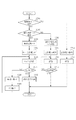
図7は、カメラ1がパケットを送信する際のカメラ1の動作を示すフローチャートである。
FIG. 7 is a flowchart showing the operation of the
図7において、カメラ1は、送信パケットが複数の相手装置に対して送るパケットかを判断する(ステップS701)。図6のように、カメラ1がブロードキャストパケットであるBEACON信号をネットワーク4に送信する場合は、複数の相手装置に対してパケットを送信すると判断し、MAC処理部106はパワー制御インタフェース108を介してRF処理部105を送信電力最大に設定する(ステップS714)。そして、BEACON信号を送信電力最大でブロードキャスト送信する(ステップS715)。なお、ブロードキャスパケットに対してはACKは返信されないので、そのまま送信処理は終了する。このように、ブロードキャストパケットのような複数の通信相手に送信するパケットを送信する場合には送信電力を最大で送信することにより、パケットに含まれる情報がネットワーク全体に情報が行き渡る。従って、パケットを受信できなかった通信装置が新たに別のネットワークを形成してしまうような不整合を防止することができる。
In FIG. 7, the
図11は、カメラ1がBEACON信号を送信する場合のシーケンス図である。カメラ1のMAC処理部101はBEACON信号の送信先を判断する(ステップS111)。BEACON信号はブロードキャストパケットなので、MAC処理部101はRF処理部105における送信電力を最大に設定する(ステップS112)。RF処理部105は、最大の送信電力でBEACON信号を送信する(ステップS113)。このBEACON信号は、ネットワーク4全体に届くことになり、プリンタ2、カメラ3で受信されることになる。
FIG. 11 is a sequence diagram when the
図7の説明に戻り、送信パケットが複数の相手装置に対して送るパケットでない場合は、カメラ1は、送信パケットの宛先が、通信対象宛てかを判断する(ステップS702)。送信パケットの宛先が、プリンタ2の場合は、カメラ機能部102から通知された送信電力制御すべき宛先のMACアドレスと一致するので、通信対象へのパケット送信と判断する。通信対象への送信の場合は、再送回数のカウンタをクリアし(ステップS703)、パケット送信をするときに利用する変数Pcを現在の送信電力値Pにする(ステップS704)。そして、送信パケットを送信電力Pcで送信する(ステップS705)。その後、送信パケットに対する応答信号であるACKが受信できたかを判断する(ステップS706)。ACKを受信した場合は、図8で示す送信電力計算のルーチンに移行する(ステップS707)。
Returning to the description of FIG. 7, when the transmission packet is not a packet to be sent to a plurality of counterpart devices, the
所定期間待ってもACKが受信できなければ、再送回数のカウンタをインクリメント(+1)し(ステップS708)、送信電力を示す変数Pcを所定量増加し(ステップS709)、もう一度、増加した送信電力Pcでパケットを送信する(ステップS705)。 If ACK cannot be received after waiting for a predetermined period, the counter of the number of retransmissions is incremented (+1) (step S708), the variable Pc indicating the transmission power is increased by a predetermined amount (step S709), and the increased transmission power Pc is once again increased. The packet is transmitted (step S705).
ここで、図8に示す送信電力計算のルーチンについて説明する。過去N回の送信時の再送回数の平均が、閾値1より小さい場合は(ステップS801)、送信電力Pを所定量減少させる(ステップS802)。また、過去N回の送信時の再送回数の平均が、閾値2(閾値2>閾値1)より大きい場合は(ステップS803)、送信電力Pを所定量増加させる(ステップS804)。また、過去N回の送信時の再送回数の平均が、閾値1以上、閾値2以下の場合は、現状の送信電力Pの値を維持する。
Here, the transmission power calculation routine shown in FIG. 8 will be described. If the average number of retransmissions in the past N transmissions is smaller than the threshold 1 (step S801), the transmission power P is decreased by a predetermined amount (step S802). If the average number of retransmissions in the past N transmissions is larger than threshold 2 (
図9は、カメラ1がプリンタ2にパケットを送信する際のシーケンス図である。まずカメラ1のMAC処理部101は、カメラ機能部102よりデータ送信の指示を受け(ステップS901)、送信するパケットの送信先を判断する(ステップS902)。送信先がプリンタ2の場合は、通信対象への送信処理なので、再送回数のカウンタをクリアし(ステップS903)、送信電力を決定する(ステップS904)。そして、決定した送信電力をRF処理部105に設定し、データパケットをプリンタ2に送信する(ステップS905)。プリンタ2はデータパケットを受信すると、ACKを送信するので、このACKをカメラ1が受信すると(ステップS906)、これ以降のパケット送信のために送信電力計算を実行する(ステップS907)。
FIG. 9 is a sequence diagram when the
ここで図4に示すように、図1のネットワーク4に新たなカメラ21が参加してきた状況を考える。カメラ21は、IPアドレスの確認のためのARP(Address Resolution Protocol)Requestパケットをネットワーク4にブロードキャストする。カメラ1は、このARP Requestパケットを受信すると、図5のように、カメラ21に対してARP Replyを返信する。このARP Replyの送信先であるカメラ21は、カメラ1にとっては予めMAC処理部106に記憶しているMACアドレスの機器ではない。よって、カメラ1は、ARP Replyの宛先が通信対象以外であると判断し(ステップS710)、送信電力を最大に設定する(ステップS711)。そして、最大の送信電力でARP Replyを送信する(ステップS712)。カメラ21がARP Replyを受信すると、ACKを返信するので、カメラ1はACKが受信できたかを判断する(ステップS713)。ACKを受信した場合は、処理を終了し、所定期間待ってもACKが受信できなければ、ARP Replyを再送する。
Here, as shown in FIG. 4, consider a situation where a
図10は、ネットワーク4に新規に参加してきたカメラ21とカメラ1とのシーケンス図である。
FIG. 10 is a sequence diagram of the
カメラ21は、ネットワーク4に参加する際に、ARP Rerquestパケットをブロードキャスト送信する(ステップS101)。カメラ1は、このARP Rerquestパケットを受信すると、ARP Replyパケットを送ることになるので、MAC処理部101は、このパケットの送信先を判断する(ステップS102)。パケットの宛先は、通信対象以外の宛先なので、MAC処理部101はRF処理部105における送信電力を最大に設定する(ステップS103)。RF処理部105は、最大の送信電力でARP Replyパケットをカメラ21に送信する(ステップS104)。よって、カメラ21にARP Replyが届く可能性が高くなり、同じIPアドレスをカメラ21に利用され、IPデータの混信が起こることを防止できる。なお、カメラ1はこのパケットに対して、ACKを受信するが(ステップS105)、カメラ21は予め決められた通信対象の通信装置ではないので、ACK受信後に送信電力計算は行わない。
When the
また、カメラ21がブロードキャストしたProbe Requestパケットをカメラ1が受信した場合は、カメラ1はProbe Responseパケットをカメラ21に送信する。この場合も、Probe Responseパケットの送信先は通信対象外なので(ステップS710)、カメラ1は送信電力を最大にし(ステップS711)、Probe Responseパケットを送信する(ステップS712)。そして、ACKの有無を判断し(ステップS713)、ACKが受信されれば処理を終了し、受信されなければProbe Responseパケットを再送する。
In addition, when the
以上のように上記説明によれば、パケットの宛先、または、送信するパケットに応じて、送信電力制御を行って送信、送信電力を最大にして送信するので、特定の基地局(アクセスポイント)を介さずに無線通信装置同士が直接通信を行うアドホックネットワークにおいて、送信電力制御を行いつつ、その副作用である、隠れ端末問題によるパケットの衝突、送信電力不足によるパケットの消失、送信電力不足によるIPアドレスの衝突を回避し、ネットワーク全体の通信品質を正常に保つことができる。 As described above, according to the destination of the packet or according to the packet to be transmitted, transmission power control is performed for transmission and transmission power is maximized, so that a specific base station (access point) is transmitted. In ad hoc networks where wireless communication devices communicate directly with each other without intervention, while performing transmission power control, its side effects are packet collision due to hidden terminal problem, packet loss due to insufficient transmission power, IP address due to insufficient transmission power Collisions can be avoided, and the communication quality of the entire network can be kept normal.
Claims (7)
データの宛先を判断する判断手段と、
前記判断手段による判断の結果、前記データの宛先が複数の通信装置であり、該データを同時に前記複数の通信装置に送信する場合は、所定の高い送信電力で該データを送信し、前記データの宛先が1台であり、送信電力制御すべき宛先として管理されている場合は、該宛先との通信状態に応じて送信電力を増減する送信電力制御を行う制御手段と、を有し、
前記制御手段は、前記データの宛先が1台であっても、アドレス確認のためのARP(Address Resolution Protocol)Requestパケットに対する応答であるARP ReplyパケットまたはProbe Requestパケットに対する応答であるProbe Responseパケットを送信する場合は、前記所定の高い送信電力で前記ARP Replyパケットまたは前記Probe Responseパケットを送信することを特徴とする通信装置。 A communication device,
A determination means for determining the destination of the data;
As a result of the determination by the determining means, when the destination of the data is a plurality of communication devices and the data is simultaneously transmitted to the plurality of communication devices, the data is transmitted with a predetermined high transmission power, and the data the destination is one that, if it is managed, possess control means for controlling the transmission power to increase or decrease the transmission power in accordance with the communication state between the destination, as a destination to be controlled transmission power,
The control means transmits a probe response packet that is a response to an ARP reply packet or a probe request packet that is a response to an address resolution protocol (ARP) request packet for address confirmation even if the data destination is one. If so, the communication apparatus transmits the ARP Reply packet or the Probe Response packet with the predetermined high transmission power .
前記判断手段は、データの宛先のアドレスが前記記憶手段に記憶されているか否かを判断することを特徴とする請求項1又は請求項2に記載の通信装置。 Having storage means for storing the address of the counterpart device;
The communication device according to claim 1, wherein the determination unit determines whether an address of a data destination is stored in the storage unit.
前記通信装置は、データの宛先を判断し、前記データの宛先が複数の通信装置であり、該データを同時に前記複数の通信装置に送信する場合は、所定の高い送信電力で該データを送信し、前記データの宛先が1台であり、送信電力制御すべき宛先として管理されている場合は、該宛先との通信状態に応じて送信電力を増減する送信電力制御を行い、前記送信電力制御は、前記データの宛先が1台であっても、アドレス確認のためのARP(Address Resolution Protocol)Requestパケットに対する応答であるARP ReplyパケットまたはProbe Requestパケットに対する応答であるProbe Responseパケットを送信する場合は、前記所定の高い送信電力で前記ARP Replyパケットまたは前記Probe Responseパケットを送信することを特徴とする通信装置の通信方法。 A communication method for a communication device, comprising:
The communication device determines a data destination, and when the data destination is a plurality of communication devices and transmits the data to the plurality of communication devices at the same time, the data is transmitted with a predetermined high transmission power. the is the destination of the data is one, if they are managed as a destination to be controlled transmission power, have line transmission power control to increase or decrease the transmission power in accordance with the communication state between the destination, the transmission power control When sending a probe response packet that is a response to an ARP reply packet or a probe request packet that is a response to an address resolution protocol (ARP) request packet for address confirmation, even if the destination of the data is one The ARP Reply at the predetermined high transmission power Communication method for a communication apparatus characterized by transmitting a packet or the Probe Response packet.
Priority Applications (3)
| Application Number | Priority Date | Filing Date | Title |
|---|---|---|---|
| JP2005057447A JP4700982B2 (en) | 2005-03-02 | 2005-03-02 | Communication apparatus and communication method |
| US11/358,205 US7555056B2 (en) | 2005-03-02 | 2006-02-22 | Communication apparatus and method |
| CN2006100581058A CN1829112B (en) | 2005-03-02 | 2006-03-02 | Communication apparatus and method |
Applications Claiming Priority (1)
| Application Number | Priority Date | Filing Date | Title |
|---|---|---|---|
| JP2005057447A JP4700982B2 (en) | 2005-03-02 | 2005-03-02 | Communication apparatus and communication method |
Publications (3)
| Publication Number | Publication Date |
|---|---|
| JP2006245897A JP2006245897A (en) | 2006-09-14 |
| JP2006245897A5 JP2006245897A5 (en) | 2008-04-17 |
| JP4700982B2 true JP4700982B2 (en) | 2011-06-15 |
Family
ID=36947276
Family Applications (1)
| Application Number | Title | Priority Date | Filing Date |
|---|---|---|---|
| JP2005057447A Expired - Fee Related JP4700982B2 (en) | 2005-03-02 | 2005-03-02 | Communication apparatus and communication method |
Country Status (3)
| Country | Link |
|---|---|
| US (1) | US7555056B2 (en) |
| JP (1) | JP4700982B2 (en) |
| CN (1) | CN1829112B (en) |
Families Citing this family (20)
| Publication number | Priority date | Publication date | Assignee | Title |
|---|---|---|---|---|
| JP4310253B2 (en) * | 2004-09-21 | 2009-08-05 | キヤノン株式会社 | Communication apparatus and communication method |
| JP4336636B2 (en) * | 2004-09-21 | 2009-09-30 | キヤノン株式会社 | Communication apparatus and communication method |
| US8527790B2 (en) * | 2004-09-21 | 2013-09-03 | Canon Kabushiki Kaisha | Communication apparatus and communication method |
| JP4549207B2 (en) * | 2005-03-15 | 2010-09-22 | キヤノン株式会社 | COMMUNICATION DEVICE AND ITS CONTROL METHOD |
| JP4777106B2 (en) * | 2006-03-22 | 2011-09-21 | キヤノン株式会社 | Communication apparatus and wireless communication control method |
| KR100781523B1 (en) * | 2006-04-25 | 2007-12-03 | 삼성전자주식회사 | Apparatus and method for structuring IP identification packet and allotting IP |
| JP4944564B2 (en) * | 2006-10-20 | 2012-06-06 | キヤノン株式会社 | COMMUNICATION PARAMETER SETTING METHOD, COMMUNICATION DEVICE, COMMUNICATION DEVICE CONTROL METHOD, AND PROGRAM |
| JP4789817B2 (en) * | 2007-01-29 | 2011-10-12 | キヤノン株式会社 | COMMUNICATION DEVICE, COMMUNICATION DEVICE COMMUNICATION METHOD, AND PROGRAM |
| JP4940037B2 (en) * | 2007-07-18 | 2012-05-30 | キヤノン株式会社 | COMMUNICATION DEVICE, COMMUNICATION DEVICE COMMUNICATION METHOD, PROGRAM, AND STORAGE MEDIUM |
| JP5270937B2 (en) | 2008-03-17 | 2013-08-21 | キヤノン株式会社 | COMMUNICATION DEVICE AND ITS CONTROL METHOD |
| WO2010034152A1 (en) * | 2008-09-25 | 2010-04-01 | 智格网信息科技(成都)有限公司 | Multi-channel wireless communication method and device with single antenna |
| TWI389582B (en) | 2008-09-25 | 2013-03-11 | Skyphy Networks Ltd | Wireless communication methods utilizing a single antenna with multiple channels and the devices thereof |
| JP5225033B2 (en) * | 2008-11-12 | 2013-07-03 | キヤノン株式会社 | COMMUNICATION DEVICE AND ITS CONTROL METHOD |
| WO2010068405A2 (en) | 2008-12-10 | 2010-06-17 | Marvell World Trade Ltd. | Efficient formats of beacon, announcement, and beamforming training frames |
| JP5852431B2 (en) | 2011-12-09 | 2016-02-03 | キヤノン株式会社 | Image processing apparatus, control method thereof, and program |
| US10371305B1 (en) * | 2012-02-22 | 2019-08-06 | SeeScan, Inc. | Dockable tripodal camera control unit |
| WO2014005054A2 (en) | 2012-06-29 | 2014-01-03 | Marvell World Trade Ltd. | Unified beacon format |
| JP6210753B2 (en) | 2013-06-24 | 2017-10-11 | キヤノン株式会社 | Information processing device |
| JP6727189B2 (en) * | 2015-03-11 | 2020-07-22 | シャープ株式会社 | Terminal device and communication method |
| JP2019036845A (en) * | 2017-08-15 | 2019-03-07 | 沖電気工業株式会社 | Radio communication equipment, radio communication program, and radio communication system |
Citations (3)
| Publication number | Priority date | Publication date | Assignee | Title |
|---|---|---|---|---|
| JPH07143047A (en) * | 1993-11-18 | 1995-06-02 | Japan Radio Co Ltd | Radio repeater in radio lan |
| JP2004215058A (en) * | 2003-01-07 | 2004-07-29 | Matsushita Electric Ind Co Ltd | Radio data communication equipment |
| JP2004297201A (en) * | 2003-03-25 | 2004-10-21 | Fujitsu Ltd | Mobile phone searching system and searching method |
Family Cites Families (9)
| Publication number | Priority date | Publication date | Assignee | Title |
|---|---|---|---|---|
| JP3013822B2 (en) * | 1997-11-20 | 2000-02-28 | 日本電気株式会社 | Spread spectrum communication system |
| KR100452502B1 (en) * | 2000-03-06 | 2004-10-08 | 엘지전자 주식회사 | A reverse power control method of packet data transmission for wll |
| JPWO2002037715A1 (en) * | 2000-10-31 | 2004-03-11 | 松下電器産業株式会社 | Mobile station apparatus and handover method |
| JP3575437B2 (en) * | 2001-05-10 | 2004-10-13 | 日本電気株式会社 | Directivity control device |
| CN1235354C (en) * | 2001-10-04 | 2006-01-04 | 株式会社Ntt都科摩 | Radio control apparatus, base station, mobile communication method, mobile communication program recording medium containing the same, and mobile communication system |
| JP4288093B2 (en) * | 2003-04-09 | 2009-07-01 | 株式会社エヌ・ティ・ティ・ドコモ | Wireless communication control system and wireless communication control method |
| WO2005001619A2 (en) * | 2003-06-06 | 2005-01-06 | Meshnetworks, Inc. | Mac protocol for accurately computing the position of wireless devices inside buildings |
| US7542452B2 (en) * | 2004-04-09 | 2009-06-02 | Sharp Laboratories Of America, Inc. | Systems and methods for implementing an enhanced multi-channel direct link protocol between stations in a wireless LAN environment |
| JP4549207B2 (en) * | 2005-03-15 | 2010-09-22 | キヤノン株式会社 | COMMUNICATION DEVICE AND ITS CONTROL METHOD |
-
2005
- 2005-03-02 JP JP2005057447A patent/JP4700982B2/en not_active Expired - Fee Related
-
2006
- 2006-02-22 US US11/358,205 patent/US7555056B2/en not_active Expired - Fee Related
- 2006-03-02 CN CN2006100581058A patent/CN1829112B/en not_active Expired - Fee Related
Patent Citations (3)
| Publication number | Priority date | Publication date | Assignee | Title |
|---|---|---|---|---|
| JPH07143047A (en) * | 1993-11-18 | 1995-06-02 | Japan Radio Co Ltd | Radio repeater in radio lan |
| JP2004215058A (en) * | 2003-01-07 | 2004-07-29 | Matsushita Electric Ind Co Ltd | Radio data communication equipment |
| JP2004297201A (en) * | 2003-03-25 | 2004-10-21 | Fujitsu Ltd | Mobile phone searching system and searching method |
Also Published As
| Publication number | Publication date |
|---|---|
| US20060203833A1 (en) | 2006-09-14 |
| CN1829112B (en) | 2011-07-06 |
| CN1829112A (en) | 2006-09-06 |
| US7555056B2 (en) | 2009-06-30 |
| JP2006245897A (en) | 2006-09-14 |
Similar Documents
| Publication | Publication Date | Title |
|---|---|---|
| JP4700982B2 (en) | Communication apparatus and communication method | |
| US8300626B2 (en) | Path shortening in a wireless mesh network | |
| RU2698155C2 (en) | Wireless communication device and wireless communication method | |
| JP3853326B2 (en) | System and method for reliably broadcasting in ad hoc network environment | |
| JP5031033B2 (en) | Automatic partner selection in collaborative MAC protocol | |
| JP5280756B2 (en) | Method for setting packet transmission route in ad hoc network and network device using the same | |
| US8837354B2 (en) | Apparatus and method for supporting wireless actuators and other devices in process control systems | |
| KR101243501B1 (en) | Apparatus and method for transmitting and receiving data in wireless local area network mesh communication system | |
| EP2498474A1 (en) | Communication terminal and communication method | |
| US10680899B1 (en) | Topology discovery through multicast transmission | |
| Yan et al. | Opportunistic network coding based cooperative retransmissions in D2D communications | |
| CN108353030B (en) | Method and apparatus for handling acknowledgements in a wireless radio ad hoc network | |
| JP6526852B2 (en) | Simultaneous transmit and receive operation in WLAN | |
| JP3599032B2 (en) | Wireless communication system, wireless communication method, and wireless station | |
| KR101013752B1 (en) | Method for transmitting a data in ad-hoc network | |
| Koutsoubelias et al. | Coordinated broadcast-based request-reply and group management for tightly-coupled wireless systems | |
| JP3950081B2 (en) | Wireless relay method and apparatus | |
| JP6265929B2 (en) | SEARCH WIRELESS COMMUNICATION DEVICE AND SEARCHED WIRELESS COMMUNICATION DEVICE | |
| JP5182625B2 (en) | Wireless communication network system, access point selection program, and storage medium storing access point selection program | |
| WO2011080554A1 (en) | Energy efficient integrated routing protocol | |
| US20230403637A1 (en) | Enhanced wireless transmission system | |
| JP2007288578A (en) | System and apparatus for wireless communication | |
| JP7034596B2 (en) | Communication equipment, communication methods, and programs | |
| CN116636297A (en) | Data packet transaction timing solution for wireless communication system | |
| US10687244B2 (en) | Methods, first transmit device and relay device for supporting wireless communication |
Legal Events
| Date | Code | Title | Description |
|---|---|---|---|
| A521 | Request for written amendment filed |
Free format text: JAPANESE INTERMEDIATE CODE: A523 Effective date: 20080229 |
|
| A621 | Written request for application examination |
Free format text: JAPANESE INTERMEDIATE CODE: A621 Effective date: 20080229 |
|
| RD04 | Notification of resignation of power of attorney |
Free format text: JAPANESE INTERMEDIATE CODE: A7424 Effective date: 20100201 |
|
| A977 | Report on retrieval |
Free format text: JAPANESE INTERMEDIATE CODE: A971007 Effective date: 20100208 |
|
| A131 | Notification of reasons for refusal |
Free format text: JAPANESE INTERMEDIATE CODE: A131 Effective date: 20100216 |
|
| A521 | Request for written amendment filed |
Free format text: JAPANESE INTERMEDIATE CODE: A523 Effective date: 20100412 |
|
| RD01 | Notification of change of attorney |
Free format text: JAPANESE INTERMEDIATE CODE: A7421 Effective date: 20100630 |
|
| A02 | Decision of refusal |
Free format text: JAPANESE INTERMEDIATE CODE: A02 Effective date: 20100831 |
|
| A521 | Request for written amendment filed |
Free format text: JAPANESE INTERMEDIATE CODE: A523 Effective date: 20101125 |
|
| A911 | Transfer to examiner for re-examination before appeal (zenchi) |
Free format text: JAPANESE INTERMEDIATE CODE: A911 Effective date: 20101203 |
|
| A01 | Written decision to grant a patent or to grant a registration (utility model) |
Free format text: JAPANESE INTERMEDIATE CODE: A01 Effective date: 20110301 |
|
| A61 | First payment of annual fees (during grant procedure) |
Free format text: JAPANESE INTERMEDIATE CODE: A61 Effective date: 20110307 |
|
| LAPS | Cancellation because of no payment of annual fees |