JP4698692B2 - MTF measuring method and MTF measuring apparatus - Google Patents
MTF measuring method and MTF measuring apparatus Download PDFInfo
- Publication number
- JP4698692B2 JP4698692B2 JP2008045631A JP2008045631A JP4698692B2 JP 4698692 B2 JP4698692 B2 JP 4698692B2 JP 2008045631 A JP2008045631 A JP 2008045631A JP 2008045631 A JP2008045631 A JP 2008045631A JP 4698692 B2 JP4698692 B2 JP 4698692B2
- Authority
- JP
- Japan
- Prior art keywords
- pixel
- edge
- mtf
- inclination angle
- pixel arrangement
- Prior art date
- Legal status (The legal status is an assumption and is not a legal conclusion. Google has not performed a legal analysis and makes no representation as to the accuracy of the status listed.)
- Expired - Fee Related
Links
Images


Description
本発明は、カメラなどの撮像装置において、レンズ及び撮像系の品質評価を行うためのパラメータとしてのMTF(Modulaion Transfer Function)を求めるMTF測定方法及びMTF測定装置に関する。 The present invention relates to an MTF measurement method and an MTF measurement apparatus for obtaining MTF (Modulation Transfer Function) as a parameter for performing quality evaluation of a lens and an imaging system in an imaging apparatus such as a camera.
従来、カメラなどの撮像装置に用いられる撮像レンズ(所謂、本発明における被検レンズである)の品質を評価する方法として、投影解像力による品質評価方法やMTFによる品質評価方法が知られている。 Conventionally, as a method for evaluating the quality of an imaging lens used in an imaging apparatus such as a camera (so-called test lens in the present invention), a quality evaluation method based on projection resolution and a quality evaluation method based on MTF are known.
投影解像力による品質評価方法は、撮像レンズを介して間隔が疎から密へと除々に変化する縞模様を投影し、その投影された縞模様をどの程度の間隔まで1本1本の縞模様として捉えることができるか否かを目視検査によって評価するものであって、検査員による評価バラツキが発生し易く、精度の高い評価データを得ることが困難であった。 In the quality evaluation method using the projection resolving power, a striped pattern in which the interval gradually changes from sparse to dense is projected through the imaging lens, and the projected striped pattern is converted into one striped pattern up to what interval. Whether or not it can be captured is evaluated by visual inspection, and it is easy for inspectors to vary in evaluation and it is difficult to obtain highly accurate evaluation data.
一方、MTFによる品質評価方法は、MTFが撮像レンズをシステムとしてみた場合の幾何学的な伝達係数であって周波数領域でみたコントラストの変調度を表し(所謂、撮像レンズの空間周波数特性を表す)、撮像レンズを介して出力した像質を表すためのパラメータとしてMTFを用いることができ、この際、検査員の目視検査による評価バラツキを低減できる。 On the other hand, the quality evaluation method using the MTF is a geometric transfer coefficient when the MTF is viewed as an imaging lens as a system, and represents the degree of contrast modulation in the frequency domain (so-called spatial frequency characteristics of the imaging lens). The MTF can be used as a parameter for representing the image quality output through the imaging lens, and in this case, the evaluation variation due to the visual inspection of the inspector can be reduced.
MTFの測定の際には、被検対象である撮像レンズと、エッジ画像を有するチャートと、複数の光電変換素子が並設されて前記エッジ画像を画素毎の電気信号に変換して出力する撮像素子(例えば、CCD:Charge Coupled Devices、CMOS:Complementary Metal Oxide Semiconductor等)とが用いられ、撮像素子から出力されたエッジ画像の画像信号を用いてMTFが算出される。 When measuring the MTF, an imaging lens that is an object to be examined, a chart having an edge image, and a plurality of photoelectric conversion elements are arranged in parallel, and the edge image is converted into an electrical signal for each pixel and output. An element (for example, CCD: Charge Coupled Devices, CMOS: Complementary Metal Oxide Semiconductor, etc.) is used, and an MTF is calculated using an image signal of an edge image output from the imaging element.
MTFは、画像のエッジ部分を含む画素範囲を、画素配置方向に走査してステップ応答として捉え、そのステップ応答した画像データを微分して像の強度分布を表すLSF(Line Speed Function)波形とし、そのLSF波形をフーリエ変換することによって、レンズ評価のための変調伝達関数として得られる。 The MTF scans the pixel range including the edge portion of the image in the pixel arrangement direction and regards it as a step response, differentiates the image data that has undergone the step response into an LSF (Line Speed Function) waveform that represents the intensity distribution of the image, The LSF waveform is Fourier transformed to obtain a modulation transfer function for lens evaluation.
また、一般に、MTFは、被検レンズ光学中心から径方向に向かう法線と、この法線に直交する接線との両方向に沿って測定され、法線方向に沿ってMTFを測定する際には、法線が画素配置方向に対して略直交するように被検レンズとエッジ模様との相対位置が設定され、一方、接線方向にMTFを測定する際には、接線が画素配置方向に対して略直交するように被検レンズとエッジ模様との相対位置が設定される(例えば、特許文献1、2、3参照)。
しかしながら、従来のMTF測定方法によれば、画素配置方向に対して傾斜する法線又は接線方向に沿ってMTFを測定する際には、法線及び接線が画素配置方向に一致するように撮像素子又は被検レンズを回動させる工程と、チャートのエッジ方向を画素配置方向に合わせる工程とが必要になるので、これらの工程を構成するための装置が複雑となり、MTFの測定が容易でなく、且つ、MTFの測定精度を損なう虞があった。 However, according to the conventional MTF measurement method, when the MTF is measured along the normal line or the tangential direction inclined with respect to the pixel arrangement direction, the image sensor is arranged so that the normal line and the tangent line coincide with the pixel arrangement direction. Alternatively, since a process of rotating the lens to be tested and a process of aligning the edge direction of the chart with the pixel arrangement direction are required, the apparatus for configuring these processes becomes complicated, and MTF measurement is not easy. In addition, there is a concern that the measurement accuracy of MTF may be impaired.
そこで、本発明は、被検レンズの光学中心から径方向に向かって任意の傾斜角を有する法線及び接線に沿ってMTFを測定する際に、撮像素子や被検レンズを回動させたりチャートのエッジ方向を調整したりすること無く、MTFを容易に且つ精度良く測定できるMTF測定方法及びMTF測定装置を提供することを目的とする。 In view of this, the present invention provides a chart or chart that rotates the image sensor and the test lens when measuring the MTF along the normal and tangent lines having an arbitrary inclination angle in the radial direction from the optical center of the test lens. It is an object of the present invention to provide an MTF measuring method and an MTF measuring apparatus capable of measuring MTF easily and accurately without adjusting the edge direction of the.
かかる目的を達成するためになされた請求項1に記載の発明は、光学像を撮像素子に導くための被検レンズと、エッジ模様が形成されたチャートと、マトリックス状に複数の光電変換素子が配置されて、前記被検レンズを介して導かれた前記チャート像を光電変換して画像信号を出力する前記撮像素子と、を用い、前記撮像素子から出力する前記画像信号に基づいて、前記エッジ模様を含む所定の画素範囲を走査し、前記被検レンズの性能を評価するための指標となるMTF(Modulation Transfer Function)を測定するMTF測定方法であって、前記被検レンズの光学中心から径方向に延出する所定の法線上に位置して前記撮像素子に結像された前記エッジ模様の、前記撮像素子の画素配置方向に対するエッジの傾斜角を検出するエッジ傾斜角検出ステップと、前記エッジ傾斜角検出ステップで検出された前記エッジの傾斜角に基づいて、前記エッジの傾斜角が前記画素配置方向に対して所定の角度になるように、前記エッジ模様を含む所定の画像範囲を傾斜させるエッジ模様傾斜ステップと、前記エッジ模様傾斜ステップで傾斜された前記エッジ模様を含む所定の画像範囲を前記撮像素子の傾斜前の画素配置に投影して、前記撮像素子の傾斜前の画素配置における画素毎の画素値を、該画素を囲む前記傾斜後の画素配置における画素値を用いて補間生成する補間生成ステップと、前記補間生成ステップによって補間生成された画素値を前記撮像素子の画素配置方向に走査して前記MTFを測定するMTF測定ステップと、を備え、前記被検レンズの光学中心から前記エッジ模様のエッジ延出方向に対して所定の角度だけ傾斜する法線及び該法線に直交する接線の少なくとも一方向に沿って、前記MTFを測定することを特徴とする。
The invention according to
請求項1に記載のMTF測定方法は、被検レンズの光学中心から径方向に延出する所定の法線上に位置して撮像素子に結像されたエッジ模様の、撮像素子の画素配置方向に対するエッジの傾斜角を検出するエッジ傾斜角検出ステップと、エッジ傾斜角検出ステップで検出されたエッジの傾斜角に基づいて、エッジの傾斜角が画素配置方向に対して所定の角度になるように、エッジ模様を含む所定の画像範囲を傾斜させるエッジ模様傾斜ステップと、エッジ模様傾斜ステップで傾斜されたエッジ模様を含む所定の画像範囲を撮像素子の傾斜前の画素配置に投影して、撮像素子の傾斜前の画素配置における画素毎の画素値を、該画素を囲む傾斜後の画素配置における画素値を用いて補間生成する補間生成ステップと、補間生成ステップによって補間生成された画素値を撮像素子の画素配置方向に走査してMTFを測定するMTF測定ステップと、を備えているので、撮像素子や披検レンズを回動させたりチャートのエッジ方向を調整したりすること無く、披検レンズの光学中心から径方向に向かって任意の傾斜角を有する法線及びこの法線に直交する接線に沿って、MTFを精度良く測定できる。
The MTF measurement method according to
次に、請求項2に記載の発明は、光学像を撮像素子に導くための被検レンズと、エッジ模様が形成されたチャートと、マトリックス状に複数の光電変換素子が配置されて、前記被検レンズを介して導かれた前記チャート像を光電変換して画像信号を出力する前記撮像素子と、を用い、前記撮像素子から出力する前記画像信号に基づいて、前記エッジ模様を含む所定の画素範囲を走査し、前記被検レンズの性能を評価するための指標となるMTF(Modulation Transfer Function)を測定するMTF測定方法であって、前記被検レンズの光学中心から径方向に延出する所定の法線上に位置して前記撮像素子に結像された前記エッジ模様の、前記撮像素子の画素配置方向に対するエッジの傾斜角を検出するエッジ傾斜角検出ステップと、前記エッジ傾斜角検出ステップで検出された前記エッジの傾斜角に基づいて、前記エッジの傾斜角が前記画素配置方向に対して所定の角度になるように、前記エッジ模様の位置を変えずに、前記所定の画素範囲における画素配置を傾斜させる画素配置傾斜ステップと、前記画素配置傾斜ステップで傾斜された前記所定の画素範囲における画素配置を前記撮像素子の傾斜前の画素配置に投影して、前記画素配置傾斜ステップで傾斜された画素配置における画素毎の画素値を、該画素を囲む傾斜前の画素配置の画素値を用いて補間生成する傾斜画素補間生成ステップと、前記傾斜画素補間生成ステップによって補間生成された画素値を前記法線又は該法線に直交する接線に沿って走査して前記MTFを測定するMTF測定ステップと、を備え、前記被検レンズの光学中心から前記エッジ模様のエッジ延出方向に対して所定の角度だけ傾斜する法線及び該法線に直交する接線の少なくとも一方向に沿って、前記MTFを測定することを特徴とする。
Next, according to the second aspect of the present invention, a test lens for guiding an optical image to an image sensor, a chart on which an edge pattern is formed, and a plurality of photoelectric conversion elements are arranged in a matrix, and the target A predetermined pixel including the edge pattern on the basis of the image signal output from the image pickup device using the image pickup device that photoelectrically converts the chart image guided through the lens and outputs an image signal. An MTF measurement method for scanning a range and measuring an MTF (Modulation Transfer Function) serving as an index for evaluating the performance of the test lens, wherein the predetermined extension extends in the radial direction from the optical center of the test lens An edge inclination that detects an inclination angle of the edge with respect to the pixel arrangement direction of the image sensor of the edge pattern imaged on the image sensor located on the normal line Based on the detection step and the inclination angle of the edge detected in the edge inclination angle detection step, the position of the edge pattern is adjusted so that the inclination angle of the edge becomes a predetermined angle with respect to the pixel arrangement direction. Without changing, a pixel arrangement inclination step for inclining a pixel arrangement in the predetermined pixel range, and a pixel arrangement in the predetermined pixel range inclined by the pixel arrangement inclination step are projected onto the pixel arrangement before the inclination of the image sensor. to the pixel value of each pixel in the inclined pixel arranged in the pixel arrangement inclined step, the inclined pixel interpolation generation step of generating interpolation using pixel values of a pixel arrangement of the front inclined surrounding the pixel, the inclined pixel An MTF measurement step for measuring the MTF by scanning the pixel value generated by the interpolation generation step along the normal line or a tangent line orthogonal to the normal line. And at least one direction of a normal line inclined by a predetermined angle with respect to the edge extending direction of the edge pattern from the optical center of the test lens and a tangent line orthogonal to the normal line, It is characterized by measuring MTF.
請求項2に記載のMTF測定方法は、被検レンズの光学中心から径方向に延出する所定の法線上に位置して撮像素子に結像されたエッジ模様の、撮像素子の画素配置方向に対するエッジの傾斜角を検出するエッジ傾斜角検出ステップと、エッジ傾斜角検出ステップで検出されたエッジの傾斜角に基づいて、エッジの傾斜角が画素配置方向に対して所定の角度になるように、エッジ模様の位置を変えずに、所定の画素範囲における画素配置を傾斜させる画素配置傾斜ステップと、画素配置傾斜ステップで傾斜された所定の画素範囲における画素配置を撮像素子の傾斜前の画素配置に投影して、画素配置傾斜ステップで傾斜された画素配置における画素毎の画素値を、該画素を囲む傾斜前の画素配置の画素値を用いて補間生成する傾斜画素補間生成ステップと、傾斜画素補間生成ステップによって補間生成された画素値を法線又は該法線に直交する接線に沿って走査してMTFを測定するMTF測定ステップと、を備えているので、撮像素子や被検レンズを回動させたりチャートのエッジ方向を調整したりすること無く、被検レンズの光学中心から径方向に向かって任意の傾斜角を有する法線及びこの法線に直交する接線に沿って、MTFを容易に且つ精度良く測定できる。
The MTF measurement method according to
また、請求項1又は請求項2に記載のMTF測定方法は、請求項3に記載の発明のように、前記MTF測定ステップで測定されたMTFを、空間周波数毎に、前記エッジ傾斜角検出ステップで検出された前記エッジの傾斜角に対応付けて補正するMTF補正ステップを備えていることにより、さらに一層、MTFの測定精度を向上できる。
The MTF measurement method according to
次に、請求項4に記載の発明は、光学像を撮像素子に導くための披検レンズと、エッジ模様が形成されたチャートと、マトリックス状に複数の光電変換素子が配置されて、前記被検レンズを介して導かれた前記チャート像を光電変換して画像信号を出力する前記撮像素子と、を備え、前記撮像素子から出力する前記画像信号に基づいて、前記エッジ模様を含む所定の画素範囲を走査し、前記被検レンズの性能を評価するための指標となるMTF(Modulation Transfer Function)を測定するMTF測定装置であって、前記被検レンズの光学中心から径方向に延出する所定の法線上に位置して前記撮像素子に結像された前記エッジ模様の、前記撮像素子の画素配置方向に対するエッジの傾斜角を検出するエッジ傾斜角検出手段と、前記エッジ傾斜角検出手段で検出された前記エッジの傾斜角に基づいて、前記エッジの傾斜角が前記画素配置方向に対して所定の角度になるように、前記エッジ模様を含む所定の画像範囲を傾斜させるエッジ模様傾斜手段と、前記エッジ模様傾斜手段で傾斜された前記エッジ模様を含む所定の画像範囲を前記撮像素子の傾斜前の画素配置に投影して、前記撮像素子の傾斜前の画素配置における画素毎の画素値を、該画素を囲む前記傾斜後の画素配置における画素値を用いて補間生成する補間生成手段と、前記補間生成手段によって補間生成された画素値を前記撮像素子の画素配置方向に走査して前記MTFを測定するMTF測定手段と、を備え、前記被検レンズの光学中心から前記エッジ模様のエッジ延出方向に対して所定の角度だけ傾斜する法線及び該法線に直交する接線の少なくとも一方向に沿って、前記MTFを測定するように構成されていることを特徴とする。
Next, the invention described in
請求項4に記載のMTF測定装置は、被検レンズの光学中心から径方向に延出する所定の法線上に位置して撮像素子に結像されたエッジ模様の、撮像素子の画素配置方向に対するエッジの傾斜角を検出するエッジ傾斜角検出手段と、エッジ傾斜角検出手段で検出されたエッジの傾斜角に基づいて、エッジの傾斜角が画素配置方向に対して所定の角度になるように、エッジ模様を含む所定の画像範囲を傾斜させるエッジ模様傾斜手段と、エッジ模様傾斜手段で傾斜されたエッジ模様を含む所定の画像範囲を撮像素子の傾斜前の画素配置に投影して、撮像素子の傾斜前の画素配置における画素毎の画素値を、該画素を囲む傾斜後の画素配置における画素値を用いて補間生成する補間生成手段と、補間生成手段によって補間生成された画素値を撮像素子の画素配置方向に走査してMTFを測定するMTF測定手段と、を備えているので、請求項1に記載の発明と同様に、撮像素子や被検レンズを回動させたりチャートのエッジ方向を調整したりすること無く、被検レンズの光学中心から径方向に向かって任意の傾斜角を有する法線及びこの法線に直交する接線に沿って、MTFを容易に且つ精度良く測定できる。
The MTF measuring apparatus according to
次に、請求項5に記載の発明は、光学像を撮像素子に導くための被検レンズと、エッジ模様が形成されたチャートと、マトリックス状に複数の光電変換素子が配置されて、前記被検レンズを介して導かれた前記チャート像を光電変換して画像信号を出力する前記撮像素子と、を備え、前記撮像素子から出力する前記画像信号に基づいて、前記エッジ模様を含む所定の画素範囲を走査し、前記被検レンズの性能を評価するための指標となるMTF(Modulation Transfer Function)を測定するMTF測定装置であって、前記被検レンズの光学中心から径方向に延出する所定の法線上に位置して前記撮像素子に結像された前記エッジ模様の、前記撮像素子の画素配置方向に対するエッジの傾斜角を検出するエッジ傾斜角検出手段と、前記エッジ傾斜角検出手段で検出された前記エッジの傾斜角に基づいて、前記エッジの傾斜角が前記画素配置方向に対して所定の角度になるように、前記エッジ模様の位置を変えずに、前記所定の画素範囲における画素配置を傾斜させる画素配置傾斜手段と、前記画素配置傾斜手段で傾斜された所定の画素範囲における画素配置を前記撮像素子の傾斜前の画素配置に投影して、前記画素配置傾斜手段で傾斜された画素配置における画素毎の画素値を、該画素を囲む傾斜前の画素配置の画素値を用いて補間生成する傾斜画素補間生成手段と、前記傾斜画素補間生成手段によって補間生成された画素値を前記法線又は該法線に直交する接線に沿って走査し、前記MTFを測定するMTF測定手段と、を備え、前記被検レンズの光学中心から前記エッジ模様のエッジ延出方向に対して所定の角度だけ傾斜する法線及び該法線に直交する接線の少なくとも一方向に沿って、前記MTFを測定するように構成されていることを特徴とする。
Next, the invention described in
請求項5に記載のMTF測定装置は、被検レンズの光学中心から径方向に延出する所定の法線上に位置して撮像素子に結像されたエッジ模様の、撮像素子の画素配置方向に対するエッジの傾斜角を検出するエッジ傾斜角検出手段と、エッジ傾斜角検出手段で検出されたエッジの傾斜角に基づいて、エッジの傾斜角が画素配置方向に対して所定の角度になるように、エッジ模様の位置を変えずに、所定の画素範囲における画素配置を傾斜させる画素配置傾斜手段と、画素配置傾斜手段で傾斜された所定の画素範囲における画素配置を撮像素子の傾斜前の画素配置に投影して、画素配置傾斜手段で傾斜された画素配置における画素毎の画素値を、該画素を囲む傾斜前の画素配置の画素値を用いて補間生成する傾斜画素補間生成手段と、傾斜画素補間生成手段によって補間生成された画素値を法線又は該法線に直交する接線に沿って走査してMTFを測定するMTF測定手段と、を備えているので、請求項2に記載の発明と同様に、撮像素子や被検レンズを回動させたりチャートのエッジ方向を調整したりすること無く、被検レンズの光学中心から径方向に向かって任意の傾斜角を有する法線及びこの法線に直交する接線に沿って、MTFを容易に且つ精度良く測定できる。
The MTF measuring apparatus according to
また、請求項4又は請求項5に記載のMTF測定装置は、請求項6に記載の発明のように、前記MTF測定手段で測定されたMTFを、空間周波数毎に、前記エッジ傾斜角検出手段で検出された前記エッジの傾斜角に対応付けて補正するMTF補正手段を備えていることにより、さらに一層、MTFの測定精度を向上できる。
Moreover , the MTF measuring apparatus according to
本発明の第1の態様におけるMTF測定方法及びMTF測定装置は、被検レンズの光学中心から径方向に延出する所定の法線上に位置して撮像素子に結像されたエッジ模様の、撮像素子の画素配置方向に対するエッジの傾斜角を検出し、次いで、検出されたエッジの傾斜角に基づいて、エッジの傾斜角が画素配置方向に対して所定の角度になるように、エッジ模様を含む所定の画像範囲を傾斜させ、次いで、傾斜されたエッジ模様を含む所定の画像範囲を撮像素子の傾斜前の画素配置に投影して、撮像素子の傾斜前の画素配置における画素毎の画素値を、該画素を囲む傾斜後の画素配置における画素値を用いて補間生成し、次いで、補間生成された画素値を撮像素子の画素配置方向に走査してMTFを測定することにより、撮像素子や被検レンズを回動させたりチャートのエッジ方向を調整したりすること無く、画素配列方向に傾斜して被検レンズの光学中心から径方向に向かって任意の傾斜角を有する法線及びこの法線に直交する接線に沿って、MTFを容易に且つ精度良く測定できる。
The MTF measuring method and the MTF measuring apparatus according to the first aspect of the present invention are for imaging an edge pattern imaged on an imaging element located on a predetermined normal extending in a radial direction from the optical center of a lens to be examined. The edge inclination angle with respect to the pixel arrangement direction of the element is detected, and then an edge pattern is included so that the inclination angle of the edge becomes a predetermined angle with respect to the pixel arrangement direction based on the detected inclination angle of the edge The predetermined image range is tilted, and then the predetermined image range including the tilted edge pattern is projected onto the pixel arrangement before tilting the image sensor, and the pixel value for each pixel in the pixel layout before tilting the image sensor is calculated. Then, interpolation generation is performed using the pixel values in the pixel arrangement after the inclination surrounding the pixel , and then the MTF is measured by scanning the pixel values generated by the interpolation in the pixel arrangement direction of the image pickup element, thereby Inspection Without rotating the lens or adjusting the edge direction of the chart, the normal line tilts in the pixel array direction and has an arbitrary tilt angle from the optical center of the lens to be tested in the radial direction, and the normal line. The MTF can be easily and accurately measured along the tangent line that is orthogonal.
また、本発明の第2の態様におけるMTF測定方法及びMTF測定装置は、被検レンズの光学中心から径方向に延出する所定の法線上に位置して撮像素子に結像されたエッジ模様の、撮像素子の画素配置方向に対するエッジの傾斜角を検出し、次いで、検出されたエッジの傾斜角に基づいて、エッジの傾斜角が画素配置方向に対して所定の角度になるように、エッジ模様の位置を変えずに、所定の画素範囲における画素配置を傾斜させ、次いで、傾斜された所定の画素範囲における画素配置を撮像素子の傾斜前の画素配置に投影して、画素配置傾斜ステップで傾斜された画素配置における画素毎の画素値を、該画素を囲む傾斜前の画素配置の画素値を用いて補間生成し、次いで、補間生成された画素値を法線又は該法線に直交する接線に沿って走査してMTFを測定することにより、撮像素子や被検レンズを回動させたりチャートのエッジ方向を調整したりすること無く、画素配列方向に対して傾斜して被検レンズの光学中心から径方向に向かって任意の傾斜角を有する法線及びこの法線に直交する接線に沿って、MTFを容易に且つ精度良く測定できる。
Further, the MTF measuring method and the MTF measuring apparatus according to the second aspect of the present invention have an edge pattern imaged on the imaging element located on a predetermined normal extending in the radial direction from the optical center of the lens to be examined. , Detecting the inclination angle of the edge with respect to the pixel arrangement direction of the image sensor, and then, based on the detected inclination angle of the edge, the edge pattern so that the inclination angle of the edge becomes a predetermined angle with respect to the pixel arrangement direction Without changing the position of the pixel, the pixel arrangement in the predetermined pixel range is inclined, and then the pixel arrangement in the inclined predetermined pixel range is projected onto the pixel arrangement before the inclination of the image sensor, and the pixel arrangement is inclined in the pixel arrangement inclination step. The pixel value for each pixel in the pixel arrangement is interpolated using the pixel value of the pixel arrangement before the inclination surrounding the pixel, and then the interpolated pixel value is a normal line or a tangent line orthogonal to the normal line Along By measuring the MTF by scanning, diameter imaging element and the sample lens without or adjusting the edge direction of the chart or rotated, tilted with respect to the pixel array direction from the optical center of the lens The MTF can be easily and accurately measured along a normal having an arbitrary inclination angle in the direction and a tangent perpendicular to the normal.
また、本発明の第1及び第2の態様におけるMTF測定方法及びMTF測定装置は、測定されたMTFを、空間周波数毎に、検出されたエッジの傾斜角に対応付けて補正したりすることにより、さらに一層、MTFの測定精度を向上できる。
In addition, the MTF measurement method and the MTF measurement apparatus according to the first and second aspects of the present invention correct the measured MTF in association with the detected tilt angle of each edge for each spatial frequency. Furthermore, the measurement accuracy of MTF can be improved.
(第1の実施形態)
次に、本発明のMTF測定方法及びMTF測定装置の第1の実施形態を図面にもとづいて説明する。
(First embodiment)
Next, a first embodiment of the MTF measuring method and MTF measuring apparatus of the present invention will be described with reference to the drawings.
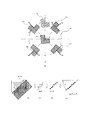
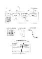
図1は、第1の実施形態のMTF測定装置の構成を表すブロック図、図2は、同実施形態における、チャートの配置及びエッジ傾斜角の検出動作を表す図である。 FIG. 1 is a block diagram showing the configuration of the MTF measurement apparatus of the first embodiment, and FIG. 2 is a diagram showing chart arrangement and edge inclination angle detection operation in the same embodiment.
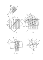
図3は、同実施形態における、画素配置方向に対して傾斜した法線及び接線方向に沿ってMTF測定範囲を設定する動作説明図であって、図3(a)が、画素配置方向に対して傾斜したエッジ模様を表した図、図3(b)が、画素配置方向に対してエッジ模様を含む所定の画像範囲を傾斜させる説明図、図3(c)が、MTFを測定する際の画素走査方向を表した図、図3(d)が傾斜させた画像範囲における画素値の補間生成方法を表した図である。 FIG. 3 is an operation explanatory diagram for setting an MTF measurement range along a normal line and a tangential direction inclined with respect to the pixel arrangement direction in the same embodiment. FIG. FIG. 3B is a diagram showing an inclined edge pattern, FIG. 3B is an explanatory diagram for tilting a predetermined image range including the edge pattern with respect to the pixel arrangement direction, and FIG. 3C is a diagram when MTF is measured. FIG. 4 is a diagram illustrating a pixel scanning direction, and FIG. 3D is a diagram illustrating an interpolation generation method of pixel values in an inclined image range.
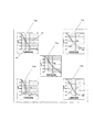
図4は、同実施形態におけるMTFの測定動作を表した図、図5は、同実施形態におけるMTFの補正方法を表した図、図6は、同実施形態のMTF測定装置で測定されたMTF曲線図である。 4 is a diagram showing an MTF measurement operation in the embodiment, FIG. 5 is a diagram showing an MTF correction method in the embodiment, and FIG. 6 is an MTF measured by the MTF measurement apparatus of the embodiment. FIG.
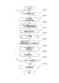
図7は、同実施形態におけるMTF測定方法の手順を表したフローチャート、図8が図7のフローチャートにおけるMTF演算の手順を表したフローチャートである。 7 is a flowchart showing the procedure of the MTF measurement method in the embodiment, and FIG. 8 is a flowchart showing the procedure of the MTF calculation in the flowchart of FIG.
図1に表したように、本実施形態のMTF測定装置1は、被検レンズLeの品質評価を行うものであって、被検レンズLeを介して導かれたチャートCH像を光電変換して複数の画素信号を出力する撮像素子(例えば、Charge Coupled Devicesである)2、撮像素子2から出力されるアナログ画像信号をデジタル画像信号に変換して出力するA/D変換器3、A/D変換器3から出力されたデジタル画像信号を画素のアドレスに対応付けて記憶するメモリ4、等を備えている。
As shown in FIG. 1, the
また、MTF測定装置1は、CPU14からの指令信号に応じて、撮像素子2及びA/D変換器3を所定の周期で制御するTG(Timing Generator)17、被検レンズLeの光軸方向のスライド駆動を行うレンズ駆動部18、センサ19aを介して被検レンズ2の光軸方向(図中のX方向)スライド量を検出するレンズ検出部19等を備えている。そして、チャートCH像が撮像素子2に合焦するように、被検レンズLeが、レンズ駆動部18を介して光軸方向に調整される。
Further, the
また、MTF測定装置1は、メモリ4からチャートCHのエッジ模様を含む所定の画像データを取得するエッジ画像取得部5、エッジ画像取得部5で取得した画像データに基づいてエッジ模様のエッジ傾斜角を検出するエッジ傾斜角検出部6、エッジ傾斜角検出部6で検出されたエッジ傾斜角に基づいてエッジ模様を含む所定の画像範囲を傾斜させるエッジ模様傾斜部7、エッジ模様傾斜部7で傾斜された所定の画像範囲の画素値を補間生成する画素値補間生成部8、画素値補間生成部8で生成された画素値を用いてMTFを測定するMTF測定手段9、CPU(Central Processing Unit)14、測定されたMTFを一時的に記憶するバッファ15、ROM(Read Only Memory)16等を備え、CPU14が、ROM16に格納された制御用プログラムに従って、当該MTF測定装置1の各処理を制御する。
Further, the
また、MTF測定手段9は、エッジ模様P0〜P4毎に、所定の画素範囲を走査してMTFを演算するMTF演算部10、MTF演算部10で演算されたMTFを補正するMTF補正部11、空間周波数に対応付けてMTF曲線を生成するMTF曲線生成部12、MTF補正部11でMTFを補正する際の補正係数を格納した補正係数記憶部13、等によって構成されている。
The MTF measuring unit 9 scans a predetermined pixel range for each of the edge patterns P0 to P4, calculates an MTF, an
図2(a)に表したように、チャートCHには、被検レンズLeの光学中心Cに対応する位置にエッジ模様P0が配置されていると共に、光学中心Cの同心円Ci状であって光学中心Cから径方向に延出する法線N1〜N4上に、複数のエッジ模様P1〜P4が配置されている。また、予め、法線N1〜N4に対して、エッジ模様P1〜P4のエッジが、所定の角度だけ傾斜して設定されている。 As shown in FIG. 2A, the chart CH has an edge pattern P0 arranged at a position corresponding to the optical center C of the lens Le to be measured, and is concentric with the optical center C and is optical. On the normal lines N1 to N4 extending in the radial direction from the center C, a plurality of edge patterns P1 to P4 are arranged. In addition, the edges of the edge patterns P1 to P4 are set in advance with a predetermined angle with respect to the normal lines N1 to N4.
また、MTF測定装置1は、後述するように、各エッジ模様に対応付けて、光学中心C近傍における画素配置方向にMTFを測定すると共に、法線N1〜N4方向及び接線T1〜T4方向にMTFを測定するように構成されている。
Further, as described later, the
エッジ画像取得部5は、エッジ模様P0〜P4毎に、エッジ模様を含む所定の画像範囲(例えば、図3(a)におけるAである)の画素データを取得する。以下、代表例として、エッジ模様P2を用い、その法線N2及び接線T2方向に沿ってMTFを測定する際の説明を行う。
The edge
次いで、エッジ傾斜角検出部6は、図2(b)〜(e)に表したように、撮像素子2の画素配置方向をxy方向として表した際に、取り込んだチャートCHのエッジ模様P2に対して、x方向にスキャンして画素値を微分してピークを求める。次いで、スキャン位置をy方向にずらして前述の工程を繰り返し、ピーク点の、yの値に対応するx方向の座標を求める。次いで、この複数のピ−ク点のxy座標に対して、最小二乗法などの直線方程式を用い、フィッテイングする直線の角度θを求める。
Next, as illustrated in FIGS. 2B to 2E, the edge inclination
次いで、エッジ模様傾斜部7は、図3(a)、(b)に表したように、エッジ傾斜角検出部6で検出されたエッジEの傾斜角θに基づいて、エッジEの傾斜角が撮像素子2の画素配置方向に対して所定の角度αになるように、エッジ模様P2及びエッジ模様P2を含む所定の画像範囲Aを傾斜させる。図3(b)において、Asが傾斜後の画像範囲を表し、P2sが傾斜後のエッジ模様を表している。
Next, as shown in FIGS. 3A and 3B, the edge
次いで、画素値補間生成部8は、図3(c)、(d)に表したように、エッジ模様傾斜部7で傾斜された画像範囲Asの傾斜前の画素配置における画素毎の画素値(D)を、該画素(D)を囲む傾斜後の画素配置における画素の画素値(A1〜A4)から補間生成する。詳しくは、エッジ模様傾斜部7で傾斜された及び所定の画像範囲As及びエッジ模様P2sを、撮像素子2の傾斜前の画素配置(画素配置R)に投影し、画素配置Rの画素座標に対応付けた画素値を生成する。
Next, as shown in FIGS. 3C and 3D, the pixel value
また、図3(d)に表したように、画素配置Rの画素座標における画素値Dを、この画素Dを囲む画素A1、画素A2、画素A3、画素A4の画素値を用い、D=k×((1/R1)×A1+(1/R2)×A2+(1/R3)×A3+(1/R4)×A4)、の演算式を用いて算出する。 Further, as shown in FIG. 3D, the pixel value D in the pixel coordinates of the pixel arrangement R is used as the pixel values of the pixels A1, A2, A3, and A4 surrounding the pixel D, and D = k It is calculated using an arithmetic expression of ((1/1 / R1) × A1 + (1 / R2) × A2 + (1 / R3) × A3 + (1 / R4) × A4)).
この演算式において、A1、A2、A3、A4、Dが、夫々、画素A1、画素A2、画素A3、画素A4、画素Dの輝度(所謂、本発明の画素値である。)を表し、R1、R2、R3、R4が、夫々、画素Dから画素A1の距離、画素Dから画素A2の距離、画素Dから画素A3の距離、画素Dから画素A4の距離を表し、kが、補正係数である。
In this arithmetic expression, A1, A2, A3, A4, and D represent the luminance of the pixel A1, the pixel A2, the pixel A3, the pixel A4, and the pixel D (so-called pixel values of the present invention) , respectively, and R1. , R2, R3, R4 respectively represent the distance from pixel D to pixel A1, the distance from pixel D to pixel A2, the distance from pixel D to pixel A3, the distance from pixel D to pixel A4, and k is a correction coefficient. is there.
つまり、画素値補間生成部8は、補間生成された画素値Dが傾斜前の画素配置を法線N2に直交するように配置変換した際の画素値であって、画素値Dを補間生成することによって、傾斜前のエッジ模様P2及びこのエッジ模様P2を含む所定の画像範囲の、法線N2方向に沿った画素座標に対応する画素値を生成する。
That is, the pixel value
次に、MTF測定手段9は、画素値補間生成部8で補間生成された画素値Dを用い、撮像素子2の画素配列方向xyに沿って画素値を走査することにより、被検レンズLeの法線N2方向及び接線T2方向のMTFを測定する。
Next, the MTF measuring means 9 uses the pixel value D interpolated and generated by the pixel value
まず、MTF演算部10は、図4(a)に表したように、チャートCHの撮像模様のエッジの傾斜角度に基づいてサンプリング数を算出し、次いで、算出されたサンプリング数を用いて、画像データを走査して画素値を取得することによりエッジのステップ応答を求め、次いで、ステップ応答を微分することによってエッジのインパルス応答を求め、次いで、インパルス応答をフーリエ変換してMTFを求める。
First, as shown in FIG. 4A, the
詳しくは、サンプリング数算出部10aでは、チャートCHにおけるエッジの傾斜角度を算出し画像の一方向の走査の基本単位となるサンプリング数P(図4(b)に表したP)を算出する。
Specifically, the sampling
図4(b)において、画像データのエッジを介して左側の輝度が暗く、右側の輝度が明るく発現している。また、図4(b)は、撮像して得られた画像データを表しており、四角い枠の1つ1つが画素を表し、画素内の△、□、●、○等が画素値を表している。
In FIG. 4B, the luminance on the left side is dark and the luminance on the right side is brightly expressed through the edge of the image data. FIG. 4B shows image data obtained by imaging, and each square frame represents a pixel, and Δ, □, ●, ○, etc. in the pixel represent pixel values. Yes.
図4(b)に表したように、チャートCHの撮像模様のエッジが垂直方向に対してわずかに傾斜している場合、主走査方向を垂直方向とし、エッジラインが垂直方向に1画素分だけ変位するようにサンプリング数Pを設定する。 As shown in FIG. 4B, when the edge of the imaging pattern of the chart CH is slightly inclined with respect to the vertical direction, the main scanning direction is the vertical direction, and the edge line is one pixel in the vertical direction. The sampling number P is set so as to be displaced.
そして、傾斜角度を求める際には、図4(e)に表したように、チャートCHのエッジに対して、y方向(垂直方向)にS個のウィンドウwを配置する。この際、1つのウィンドウは、x方向(水平方向)に複数の単位要素を有し、各単位要素のサイズは画素1個分とする。 When obtaining the tilt angle, as shown in FIG. 4E, S windows w are arranged in the y direction (vertical direction) with respect to the edge of the chart CH. In this case, one window has a plurality of unit elements in the x direction (horizontal direction), and the size of each unit element is one pixel.
次に、(式1)を用いて、各ウィンドウw内で2次微分を行う。
LW(x)=2*PW(x)−PW(x−1)−PW(x+1)・・・(式1)
Next, second order differentiation is performed in each window w using (Equation 1).
L W (x) = 2 * P W (x) −P W (x−1) −P W (x + 1) (Formula 1)
(式1)において、PW(x)がウィンドウw内の点(x,EyW)における画素値であり、LW(x)がその点における2次微分値である。また、点(x,EyW)は、1つの単位要素をx座標およびy座標の一目盛とした場合の位置であって、EyWが図3(e)中の1,2,3,・・・,Sに相当する。 In (Expression 1), P W (x) is a pixel value at a point (x, Ey W ) in the window w, and L W (x) is a secondary differential value at that point. A point (x, Ey W ) is a position when one unit element is a scale of x and y coordinates, and Ey W is 1, 2, 3,. .., corresponds to S.
次に、各ウィンドウw内において、2次微分値LW(x)の最大値LmaxWと最小値LminWを求め、それらの点のx座標XmaxW、XminWを求め、(式2)を用いて、ウィンドウw内でのエッジ点のx座標ExWを求める。
ExW=(XminW*|LmaxW|+XmaxW*|LminW|)/(|LmaxW|+|LminW|)・・・(式2)
Next, in each window w, the maximum value Lmax W and the minimum value Lmin W of the secondary differential value L W (x) are obtained, and the x-coordinates Xmax W and Xmin W of those points are obtained. used to determine the x-coordinate Ex W of edge points in the window w.
Ex W = (Xmin W * | Lmax W | + Xmax W * | Lmin W |) / (| Lmax W | + | Lmin W |) (Formula 2)
そして、(式2)より得られたエッジ点群からエッジラインの傾斜角度α1を求め、この際のcotα1を四捨五入して得られた整数値をサンプリング数Pとする。 Then, the inclination angle α1 of the edge line is obtained from the edge point group obtained from (Equation 2), and the integer value obtained by rounding off cot α1 at this time is set as the sampling number P.
次に、ステップ応答算出部10bは、図4(c)に表したように、まず、1列目の画素を垂直方向に沿ってサンプリング数Pの分だけスキャンし、1列目のスキャンが終了したら、水平方向にスキャン位置を移し、再び垂直方向に沿ってサンプリング数Pの分だけスキャンし、順次、画像データを垂直方向に沿ってサンプリング数Pずつスキャンする。
Next, as shown in FIG. 4C, the step
そして、図4(d)に表したように、各スキャン位置の画素値を取得して、各スキャン位置の画素値を一元的に並べ、エッジのステップ応答を得る。図4(d)は、縦軸に輝度値、横軸にスキャン位置を表している。 Then, as shown in FIG. 4D, the pixel values at the respective scan positions are acquired, the pixel values at the respective scan positions are arranged in a unified manner, and an edge step response is obtained. In FIG. 4D, the vertical axis represents the luminance value and the horizontal axis represents the scan position.
すなわち、ステップ応答算出部10bにおいて、エッジ付近の画素値を垂直方向にサンプリング数Pずつスキャンして、スキャンした順番に画素値を並べることにより、エッジのステップ応答を得ることができる。また、図4(d)において、エッジがより明確に捉えられているほど立ち上り又は立下りの勾配が急になって現れる。
That is, the step
また、インパルス応答算出部10cは、ステップ応答算出部10bで得られたステップ応答を微分することによって像の強度分布を表すインパルス応答に変換する。ここで行う微分は、例えば、ステップ応答の隣接する画素間の差分をとることによって行うことができる。
The impulse response calculation unit 10c converts the step response obtained by the step
また、MTF算出部10dは、インパルス応答算出部10cにより求められたインパルス応答をフーリエ変換することにより変調伝達関数であるMTFを求める。この際、フーリエ変換することより、周波数毎に実数部分と虚数部分が得られ、この実数部分と虚数部分をベクトル的に加算することによってMTFを取得する。また、MTFの算出方法については、これに限らず、例えば、ISO(International Organization for Standardization)12233に記載の解像度測定方法を用いてもよい。
Further, the
次に、MTF補正部11は、MTF演算部10で算出されたMTFを、補正係数記憶部13に格納された補正係数mを用いて補正する。
Next, the
補正係数mは、予め、図2(a)に表したように、エッジ模様P1〜P4及び法線N1〜N4を撮像素子2の画素配置xy直線上方向に配置(例えば、図中のPrの配置である)して測定したMTFを基準のMTF(図5(a)のA)とし、基準のMTFに対して、MTF演算部10で算出されたMTF(図5(a)のB)の差を補正するように設定されている。
As shown in FIG. 2A, the correction coefficient m is preliminarily arranged with the edge patterns P1 to P4 and the normal lines N1 to N4 in the pixel arrangement xy straight line direction of the image sensor 2 (for example, Pr of FIG. The MTF measured by the
また、補正係数mは、図5(b)に表したように、予め、傾斜角θ毎に空間周波数Fに対応付けて測定され、補正係数記憶部13に格納されている。
Further, as shown in FIG. 5B, the correction coefficient m is measured in advance in association with the spatial frequency F for each inclination angle θ and stored in the correction
次に、図6に表したように、MTF曲線生成部12は、MTF演算部10を介して算出されたMTFデータに基づいて、横軸に空間周波数、縦軸にコントラストの変調度を表した複数のMTF曲線12a、12b、12c、12d、12eを生成する。また、このMTF曲線中、破線で示すnLが法線方向に延出するエッジ方向のMTFを表し、実線で示すtLが接線方向に延出するエッジ方向のMTFを表している。
Next, as shown in FIG. 6, the MTF
また、MTF曲線12a〜12eは、複数のエッジ模様P0〜P4の夫々に対応付けられて生成され、画面中央に配置されたエッジ模様P0を読み取ったMTFがMTF曲線12aで表され、画面左上に配置されたエッジ模様P1を読み取ったMTFがMTF曲線12bで表され、画面右上に配置されたエッジ模様P4を読み取ったMTFがMTF曲線12cで表され、画面左下に配置されたエッジ模様P2を読み取ったMTFがMTF曲線12dで表され、画面右下に配置されたエッジ模様P3を読み取ったMTFがMTF曲線12eで表されている。
Further, the MTF curves 12a to 12e are generated in association with the plurality of edge patterns P0 to P4, and the MTF obtained by reading the edge pattern P0 arranged at the center of the screen is represented by the
そして、本実施例のMTF測定装置1では、MTF測定手段9によって測定されたMTF測定結果及びMTF曲線がバッファ15に記憶されると共に、MTF測定結果及びMTF曲線を表示する表示装置(図示せず)が備えられている。
In the
なお、本発明の請求項4におけるエッジ傾斜角検出手段がエッジ傾斜角検出部6によってその機能が発現され、本発明の請求項4におけるエッジ模様傾斜手段がエッジ模様傾斜部7によってその機能が発現され、本発明の請求項4における補間生成手段が画素値補間生成部8によってその機能が発現され、本発明の請求項6におけるMTF補正手段がMTF補正部11及び補正係数記憶部13等によってその機能が発現される。
Incidentally, the function definitive edge slope angle detecting means in
次に、図7、図8を用いて、第1の実施形態におけるMTF測定方法の手順を説明する。この、この手順は、CPU14がROM16に格納されたプログラムにもとづいて、各機能部に指令信号を与えて実行する。また、図7、図8におけるSはステップを表している。
Next, the procedure of the MTF measurement method in the first embodiment will be described with reference to FIGS. This procedure is executed by the
まず、この手順は、オペレータによってMTF測定装置1に起動信号が入力された際にスタートし、メモリ4やバッファに15に記憶されている以前の測定データを消去して初期化し、その後、S100に移る。
First, this procedure starts when an activation signal is input to the
次いで、S100において、エッジ画像取得部5を用い、チャートCHにおける複数のエッジ模様P0〜P4の内、測定対象となるエッジ模様を選択し、選択されたエッジ模様に対応付けてこのエッジ模様を含む画像データをメモリ4から取得し、その後、S200に移る。この際、複数のエッジ模様P0〜P4の選択順が、予めROM16に記憶されている。
Next, in S100, the edge
次いで、S200において、エッジ傾斜角検出部6を用い、エッジの傾斜角度θを算出し、その後、S300に移る。
Next, in S200, the edge inclination
次いで、S300において、エッジ模様傾斜部7を用い、エッジの傾斜角θが画素配置方向に対して所定の角度αになるように、エッジ模様を含む所定の画像範囲Aを傾斜させ(図3(a)、(b)参照)、その後、S400に移る。
Next, in S300, the edge pattern inclined
次いで、S400において、画素値補間生成部8を用い、S300で傾斜された所定の画像範囲における画素値を、傾斜前の元の画素値から補間生成し(図3(d)参照)、その後、S500に移る。
Next, in S400, the pixel value
次いで、S500において、図8に表した手順に基づいて、MTF演算部10を用い、MTFの演算を行う。
Next, in S500, the MTF is calculated using the
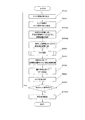
まず、図8のS510において、サンプリング数算出部10aを用い、S300で傾斜されたエッジの傾斜角度に基づいて、画像の一方向の走査の基本単位となるサンプリング数Pを算出する(図4(b)参照)。
First, in S510 of FIG. 8, the sampling
次いで、ステップ応答算出部10bを用い、S520において、主走査方向にサンプリング数Pを1ライン分の走査とするようにスキャン(図4(c)参照)してスキャン位置の画素値を取得し、その後、S530において、S520で得られた各スキャン位置の画素値を一元的に並べる(図4(d)参照)ことにより、エッジのステップ応答を得てS540に移る。
Next, using the step
次いで、S540において、インパルス応答算出部10cを用い、S530で得られたステップ応答を微分することによって像の強度分布を表すインパルス応答に変換し、S550に移る。 Next, in S540, the impulse response calculator 10c is used to differentiate the step response obtained in S530 into an impulse response representing the intensity distribution of the image, and the process proceeds to S550.
次いで、S550において、MTF算出部10dを用い、S540で得られたインパルス応答を離散フーリエ変換してMTFを算出し、その後、図7のS600に移る。
Next, in S550, the
次いで、S600において、S200で検出されたエッジの傾斜角度θに基づいて、空間周波数Fに対応付けて補正係数記憶部13に格納された補正係数m(図5(b)参照)を取得し、その後、S700に移る。
Next, in S600, based on the edge inclination angle θ detected in S200, the correction coefficient m (see FIG. 5B) stored in the correction
次いで、S700において、MTF補正部11を用い、S550で算出されたMTFに対してS600で取得した補正係数mに基づいて補正を加え、その後、S800に移る。
Next, in S700, the
次いで、S800において、MTF曲線生成部12を用い、横軸に空間周波数、縦軸にコントラストの変調度を表したMTF曲線の画像データを生成し(図6参照)、その後、S900に移る。
Next, in S800, the MTF
次いで、S900において、次のエッジ画像が有るか否か(つまり、エッジ模様P0〜P4の内で次に画像読み込みが設定されたエッジが有るか否か)を判定し、次のエッジ画像が無い(No)と判定された場合にはS1000に移り、一方、次のエッジ画像が有る(Yes)と判定された場合には、次のエッジ画像を選択して、S100からS900を繰り返す。 Next, in S900, it is determined whether there is a next edge image (that is, whether there is an edge for which image reading is set next in the edge patterns P0 to P4), and there is no next edge image. If it is determined (No), the process proceeds to S1000. On the other hand, if it is determined that there is a next edge image (Yes), the next edge image is selected, and S100 to S900 are repeated.
次いで、S1000において、S100〜S800において求められたエッジ模様毎のMT演算結果及びMTF曲線生成結果等をバッファ15に記憶し、MTF測定方法の本手順を終了する。これにより、複数のエッジ模様P0〜P4に対応する法線及び接線毎に、MTF演算が行われてMTF曲線が生成される。
Next, in S1000, the MT calculation result and the MTF curve generation result for each edge pattern obtained in S100 to S800 are stored in the
なお、本発明の請求項1におけるエッジ傾斜角検出ステップがS200によってその機能が発現され、本発明の請求項1におけるエッジ模様傾斜ステップがS300によってその機能が発現され、本発明の請求項1における補間生成ステップがS400よってその機能が発現され、本発明の請求項3におけるMTF補正ステップがS600及びS700等によってその機能が発現される。
The function of the edge inclination angle detecting step in
以上のように、第1の実施形態のMTF測定装置1及びMTF測定方法は、エッジ傾斜角検出部6を用いて、被検レンズLeの光学中心から径方向に延出する所定の法N1〜N4線上に位置して撮像素子2に結像されたエッジ模様P1〜P4の、撮像素子2の画素配置方向に対するエッジの傾斜角θを検出し、次いで、エッジ模様傾斜部7を用いて、エッジの傾斜角θに基づいて、エッジの傾斜角が画素配置方向に対して所定の角度αになるように、エッジ模様を含む所定の画像範囲Aを傾斜させ、次いで、画素値補間生成部8を用いて、傾斜されたエッジ模様を含む所定の画像範囲Asを撮像素子2の傾斜前の画素配置Rに投影して、撮像素子2の傾斜前の画素配置における画素毎の画素値(図3(d)中のDの画素値)を、該画素を囲む傾斜後の画素配置における画素値(図3(d)中のA1〜A4)を用いて補間生成し、次いで、補間生成された画素値を撮像素子2の画素配置方向(図3(a)中のx、y方向)に走査してMTFを測定することにより、撮像素子2や被検レンズLeを回動させたりチャートChのエッジ方向を調整したりすること無く、被検レンズLeの光学中心Cから任意の傾斜角を有する法線(N1〜N4)及びこの法線に直交する接線(T1〜T4)に沿って、MTFを容易に且つ精度良く測定できる。
As described above, the
また、本発明の第1の実施形態のMTF測定装置1及びMTF測定方法は、MTF補正部11を用いて、MTF演算部10で測定されたMTFを空間周波数Fに対応付けて補正したり、エッジ模様を含む所定の画素範囲を傾斜させる際の傾斜角θに対応付けて補正したりすることにより、MTFの測定精度を向上できる。
Further, the
(第2の実施形態)
次に、本発明のMTF測定方法及びMTF測定装置の第2の実施形態を、図面に基づいて説明する。
(Second Embodiment)
Next, a second embodiment of the MTF measuring method and MTF measuring apparatus of the present invention will be described based on the drawings.
本発明の第2の実施形態のMTF測定装置は、第1の実施形態で表したエッジ模様傾斜部7と画素値補間生成部8の動作が異なるものであって、基本的には第1の実施形態のMTF測定装置1と同じ構成であるので、共通となる構成部分については説明を省き、特徴となる部分について以下に説明する。また、第2の実施形態においては、エッジ模様傾斜部をエッジ模様傾斜部7bと称し、画素値補間生成部を画素値補間生成部8bと称して説明する。
The MTF measuring apparatus according to the second embodiment of the present invention is different in the operations of the edge pattern inclined
図9は、本発明の第2の実施形態における、画素配置方向に対して傾斜した法線及び接線方向に沿ってMTF測定範囲を設定する動作説明図であって、図9(a)が、撮像素子の画素配置方向に対して傾斜したエッジ模様を表した図、図9(b)が、撮像素子の画素配置方向に対して所定の画素範囲を傾斜させる説明図、図9(c)が、MTFを測定する際の画素走査方向を表した図、図9(d)が、傾斜させた画素範囲における画素値の補間生成方法を表した図である。また、図10は、同第2の実施形態における、MTF測定方法の手順を表したフローチャートである。 FIG. 9 is an operation explanatory diagram for setting the MTF measurement range along the normal line and the tangential direction inclined with respect to the pixel arrangement direction in the second embodiment of the present invention. FIG. 9B is a diagram showing an edge pattern inclined with respect to the pixel arrangement direction of the image sensor, and FIG. 9B is an explanatory diagram in which a predetermined pixel range is inclined with respect to the pixel arrangement direction of the image sensor. FIG. 9D is a diagram showing a pixel scanning direction when MTF is measured, and FIG. 9D is a diagram showing an interpolation generation method of pixel values in a tilted pixel range. FIG. 10 is a flowchart showing the procedure of the MTF measurement method in the second embodiment.
まず、図9(a)に表したように、エッジ画像取得部5が、メモリ4からチャートCHのエッジ模様を含む所定の画像データを取得する。以下、第1の実施形態と同様に、代表例として、エッジ模様P2を用い、その法線N2及び接線T2方向に沿ってMTFを測定する際の説明を行う。
First, as illustrated in FIG. 9A, the edge
次いで、図9(b)に表したように、エッジ模様傾斜部7bは、エッジ傾斜角検出部6で検出されたエッジEの画素配置方向に対する傾斜角θ(図9(a)に基づいて、エッジEの傾斜角が画素配置方向に対して所定の角度αになるように、エッジ模様P2の位置を変えずに、所定の画素範囲Aの画素配置を傾斜させる(Bの位置に傾斜させる)。
Next, as shown in FIG. 9B, the edge pattern inclined portion 7 b is based on the inclination angle θ of the edge E detected by the edge inclination
次いで、図9(c)、(d)に表したように、画素値補間生成部8bは、エッジ模様傾斜部7bで傾斜された画素配置Bにおける画素値を、傾斜前の画素配置Aの画素値から補間生成する。
Next, as illustrated in FIGS. 9C and 9D, the pixel value interpolation generation unit 8 b uses the pixel value in the pixel arrangement B inclined by the edge pattern inclination unit 7 b as the pixel of the pixel arrangement A before the inclination. Interpolate from the value.
つまり、図9(d)に表したように、エッジ模様傾斜部7bで傾斜された所定の画素範囲Bを、撮像素子2の画素配置方向に沿った画素配置Aに投影し、画素配置Bの画素座標に対応する画素Dの画素値Dを、この画素Dを囲む画素A1、画素A2、画素A3、画素A4の画素値を用い、D=k×((1/R1)×A1+(1/R2)×A2+(1/R3)×A3+(1/R4)×A4)、の演算式を用いて算出する。
That is, as shown in FIG. 9D, the predetermined pixel range B inclined by the edge pattern inclined portion 7 b is projected onto the pixel arrangement A along the pixel arrangement direction of the
この演算式において、A1、A2、A3、A4、Dが、夫々、画素A1、画素A2、画素A3、画素A4、画素Dの輝度を表し、R1、R2、R3、R4が、夫々、画素Dから画素A1の距離、画素Dから画素A2の距離、画素Dから画素A3の距離、画素Dから画素A4の距離を表し、kが補正係数である。 In this arithmetic expression, A1, A2, A3, A4, and D represent the luminance of the pixel A1, pixel A2, pixel A3, pixel A4, and pixel D, respectively, and R1, R2, R3, and R4 represent the pixel D, respectively. Represents the distance from pixel A1 to pixel A1, the distance from pixel D to pixel A2, the distance from pixel D to pixel A3, the distance from pixel D to pixel A4, and k is a correction coefficient.
なお、本発明の請求項5における画素配置傾斜手段がエッジ模様傾斜部7bによってその機能が発現され、本発明の請求項5における傾斜画素補間生成手段が画素値補間生成部8bによってその機能が発現される。
Incidentally, the function pixel arrangement inclination means definitive in
次に、第2の実施形態におけるMTF測定方法は、図10に表したように、第1の実施形態に対してS300AとS400Aが異なる。 Next, as shown in FIG. 10, the MTF measurement method in the second embodiment is different in S300A and S400A from the first embodiment.
つまり、S300Aにおいて、エッジ模様傾斜部7bを用い、S200で検出されたエッジEの画素配置方向に対する傾斜角θ(図9(a)に基づいて、画素配置方向に対して、撮像素子2に結像されたエッジ模様のエッジEの傾斜角が所定の角度αになるように、エッジ模様P2の位置を変えずに、所定の画素範囲における画素配置Aを、Bの位置に傾斜させ、(図9(a)、(b)参照)、その後、S400Aに移る。
That is, in S300A, the edge pattern inclined portion 7b is used, and the inclination angle θ of the edge E detected in S200 with respect to the pixel arrangement direction (based on FIG. 9A) is connected to the
次いで、S400Aにおいて、画素値補間生成部8bを用い、S300Aで傾斜された画素配置における画素毎の画素値を、この画素を囲む傾斜前の画素配置における画素の画素値から補間生成し(図9(c)、(d)参照)、その後、S500に移る。
Next, in S400A, the pixel value interpolation generation unit 8b is used to interpolate and generate pixel values for each pixel in the pixel arrangement inclined in S300A from the pixel values in the pixel arrangement before inclination surrounding the pixel (FIG. 9). (See (c) and (d)), and then the process proceeds to S500.
なお、本発明の請求項2における画素配置傾斜ステップがS300Aによってその機能が発現され、本発明の請求項2における傾斜画素補間生成ステップがS400Aよってその機能が発現される。
In addition, the function of the pixel arrangement inclination step in
以上のように、第2の実施形態のMTF測定装置1及びMTF測定方法は、エッジ模様傾斜部7bを用いて、エッジの傾斜角が画素配置方向に対して所定の角度αになるように、エッジ模様の位置を変えずに、所定の画素範囲における画素配置を傾斜させ、次いで、画素値補間生成部8を用いて、傾斜された所定の画素範囲における画素配置(図9(b)のB)を撮像素子の傾斜前の画素配置(図9(b)のA)に投影して、傾斜された画素配置における画素毎の画素値(図9(d)のD)を、該画素を囲む傾斜前の画素配置の画素値(A1〜A4)を用いて補間生成し、次いで、補間生成された画素値を法線又は該法線に直交する接線(図9(c)のT2)に沿って走査してMTFを測定することにより、撮像素子2や被検レンズLeを回動させたりチャートCHのエッジ方向を調整したりすること無く、画素配列方向に対して傾斜し被検レンズLeの光学中心から径方向に向かって任意の傾斜角を有する法線(N1〜N4)及びこの法線に直交する接線(T1〜T4)に沿って、MTFを容易に且つ精度良く測定できる。
As described above, the
また、本発明の第2の実施形態のMTF測定装置1及びMTF測定方法は、MTF補正部11を用いて、MTF演算部10で測定されたMTFを空間周波数Fに対応付けて補正したり、所定の画素範囲の画素配置を傾斜させる際の傾斜角θに対応付けて補正したりすることにより、MTFの測定精度を向上できる。
Moreover, the
以上、本発明の一実施例について説明したが、本発明は前記実施例に限定されるものでなく、種々態様を取ることができる。 As mentioned above, although one Example of this invention was described, this invention is not limited to the said Example, A various aspect can be taken.
1…MTF測定装置、2…撮像素子(例えば、Charge Coupled Devices)、3…A/D変換器、4…メモリ、5…エッジ画像取得部、6…エッジ傾斜角検出部、7…エッジ模様傾斜部、8…画素値補間生成部、9…MTF測定手段、10…MTF演算部、10a…サンプリング数算出部、10b…ステップ応答算出部、10c…インパルス応答算出部、10d…MTF算出部、11…MTF補正部、12…MTF曲線生成部、13…補正係数記憶部、14…CPU(Central Processing Unit)、15…バッファ、16…ROM(Read Only Memory)、17…TG(Timing Generator)、18…レンズ駆動部、19…検出部、19a…センサ、Le…被検レンズ、CH…チャート、P0〜P4…エッジ模様、Ci…同心円上、N1〜N4…法線、T1〜T4…接線。
DESCRIPTION OF
Claims (6)
エッジ模様が形成されたチャートと、
マトリックス状に複数の光電変換素子が配置されて、前記被検レンズを介して導かれた前記チャート像を光電変換して画像信号を出力する前記撮像素子と、を用い、
前記撮像素子から出力する前記画像信号に基づいて、前記エッジ模様を含む所定の画素範囲を走査し、前記被検レンズの性能を評価するための指標となるMTF(Modulation Transfer Function)を測定するMTF測定方法であって、
前記被検レンズの光学中心から径方向に延出する所定の法線上に位置して前記撮像素子に結像された前記エッジ模様の、前記撮像素子の画素配置方向に対するエッジの傾斜角を検出するエッジ傾斜角検出ステップと、
前記エッジ傾斜角検出ステップで検出された前記エッジの傾斜角に基づいて、前記エッジの傾斜角が前記画素配置方向に対して所定の角度になるように、前記エッジ模様を含む所定の画像範囲を傾斜させるエッジ模様傾斜ステップと、
前記エッジ模様傾斜ステップで傾斜された前記エッジ模様を含む所定の画像範囲を前記撮像素子の傾斜前の画素配置に投影して、前記撮像素子の傾斜前の画素配置における画素毎の画素値を、該画素を囲む前記傾斜後の画素配置における画素値を用いて補間生成する補間生成ステップと、
前記補間生成ステップによって補間生成された画素値を前記撮像素子の画素配置方向に走査して前記MTFを測定するMTF測定ステップと、
を備え、
前記被検レンズの光学中心から前記エッジ模様のエッジ延出方向に対して所定の角度だけ傾斜する法線及び該法線に直交する接線の少なくとも一方向に沿って、前記MTFを測定することを特徴とするMTF測定方法。 A test lens for guiding an optical image to the image sensor;
A chart on which an edge pattern is formed;
A plurality of photoelectric conversion elements are arranged in a matrix, and the imaging element that photoelectrically converts the chart image guided through the test lens and outputs an image signal, and
Based on the image signal output from the image sensor, a predetermined pixel range including the edge pattern is scanned, and an MTF (Modulation Transfer Function) serving as an index for evaluating the performance of the test lens is measured. A measuring method,
An edge inclination angle with respect to the pixel arrangement direction of the image sensor of the edge pattern formed on the image sensor located on a predetermined normal extending in the radial direction from the optical center of the test lens is detected. Edge inclination angle detection step;
Based on the edge inclination angle detected in the edge inclination angle detection step, a predetermined image range including the edge pattern is set such that the edge inclination angle is a predetermined angle with respect to the pixel arrangement direction. An edge pattern inclination step to be inclined;
Projecting a predetermined image range including the edge pattern tilted in the edge pattern tilting step onto a pixel arrangement before tilting the image sensor, and a pixel value for each pixel in the pixel layout before tilting the image sensor, An interpolation generation step of generating an interpolation using a pixel value in the pixel arrangement after the inclination surrounding the pixel ;
An MTF measurement step of measuring the MTF by scanning the pixel value interpolated and generated by the interpolation generation step in the pixel arrangement direction of the imaging element ;
With
Measuring the MTF along at least one direction of a normal line inclined by a predetermined angle with respect to the edge extending direction of the edge pattern from the optical center of the test lens and a tangent line orthogonal to the normal line. A characteristic MTF measurement method.
エッジ模様が形成されたチャートと、
マトリックス状に複数の光電変換素子が配置されて、前記被検レンズを介して導かれた前記チャート像を光電変換して画像信号を出力する前記撮像素子と、を用い、
前記撮像素子から出力する前記画像信号に基づいて、前記エッジ模様を含む所定の画素範囲を走査し、前記被検レンズの性能を評価するための指標となるMTF(Modulation Transfer Function)を測定するMTF測定方法であって、
前記被検レンズの光学中心から径方向に延出する所定の法線上に位置して前記撮像素子に結像された前記エッジ模様の、前記撮像素子の画素配置方向に対するエッジの傾斜角を検出するエッジ傾斜角検出ステップと、
前記エッジ傾斜角検出ステップで検出された前記エッジの傾斜角に基づいて、前記エッジの傾斜角が前記画素配置方向に対して所定の角度になるように、前記エッジ模様の位置を変えずに、前記所定の画素範囲における画素配置を傾斜させる画素配置傾斜ステップと、
前記画素配置傾斜ステップで傾斜された前記所定の画素範囲における画素配置を前記撮像素子の傾斜前の画素配置に投影して、前記画素配置傾斜ステップで傾斜された画素配置における画素毎の画素値を、該画素を囲む傾斜前の画素配置の画素値を用いて補間生成する傾斜画素補間生成ステップと、
前記傾斜画素補間生成ステップによって補間生成された画素値を前記法線又は該法線に直交する接線に沿って走査して前記MTFを測定するMTF測定ステップと、
を備え、
前記被検レンズの光学中心から前記エッジ模様のエッジ延出方向に対して所定の角度だけ傾斜する法線及び該法線に直交する接線の少なくとも一方向に沿って、前記MTFを測定することを特徴とするMTF測定方法。 A test lens for guiding an optical image to the image sensor;
A chart on which an edge pattern is formed;
A plurality of photoelectric conversion elements are arranged in a matrix, and the imaging element that photoelectrically converts the chart image guided through the test lens and outputs an image signal, and
Based on the image signal output from the image sensor, a predetermined pixel range including the edge pattern is scanned, and an MTF (Modulation Transfer Function) serving as an index for evaluating the performance of the test lens is measured. A measuring method,
An edge inclination angle with respect to the pixel arrangement direction of the image sensor of the edge pattern formed on the image sensor located on a predetermined normal extending in the radial direction from the optical center of the test lens is detected. Edge inclination angle detection step;
Based on the edge inclination angle detected in the edge inclination angle detection step, without changing the position of the edge pattern so that the edge inclination angle is a predetermined angle with respect to the pixel arrangement direction, A pixel placement tilting step for tilting the pixel placement in the predetermined pixel range;
The pixel arrangement in the predetermined pixel range inclined in the pixel arrangement inclination step is projected onto the pixel arrangement before inclination of the image sensor, and the pixel value for each pixel in the pixel arrangement inclined in the pixel arrangement inclination step is calculated. , An inclined pixel interpolation generation step for generating an interpolation using the pixel value of the pixel arrangement before the inclination surrounding the pixel;
An MTF measurement step of measuring the MTF by scanning the pixel value interpolated and generated by the inclined pixel interpolation generation step along the normal line or a tangent line orthogonal to the normal line ;
With
Measuring the MTF along at least one direction of a normal line inclined by a predetermined angle with respect to the edge extending direction of the edge pattern from the optical center of the test lens and a tangent line orthogonal to the normal line. A characteristic MTF measurement method.
ことを特徴とする請求項1又は請求項2に記載のMTF測定方法。 An MTF correction step of correcting the MTF measured in the MTF measurement step in association with the edge inclination angle detected in the edge inclination angle detection step for each spatial frequency;
The MTF measuring method according to claim 1 or claim 2, wherein
マトリックス状に複数の光電変換素子が配置されて、前記被検レンズを介して導かれた前記チャート像を光電変換して画像信号を出力する前記撮像素子と、を備え、
前記撮像素子から出力する前記画像信号に基づいて、前記エッジ模様を含む所定の画素範囲を走査し、前記被検レンズの性能を評価するための指標となるMTF(Modulation Transfer Function)を測定するMTF測定装置であって、
前記被検レンズの光学中心から径方向に延出する所定の法線上に位置して前記撮像素子に結像された前記エッジ模様の、前記撮像素子の画素配置方向に対するエッジの傾斜角を検出するエッジ傾斜角検出手段と、
前記エッジ傾斜角検出手段で検出された前記エッジの傾斜角に基づいて、前記エッジの傾斜角が前記画素配置方向に対して所定の角度になるように、前記エッジ模様を含む所定の画像範囲を傾斜させるエッジ模様傾斜手段と、
前記エッジ模様傾斜手段で傾斜された前記エッジ模様を含む所定の画像範囲を前記撮像素子の傾斜前の画素配置に投影して、前記撮像素子の傾斜前の画素配置における画素毎の画素値を、該画素を囲む前記傾斜後の画素配置における画素値を用いて補間生成する補間生成手段と、
前記補間生成手段によって補間生成された画素値を前記撮像素子の画素配置方向に走査して前記MTFを測定するMTF測定手段と、
を備え、
前記被検レンズの光学中心から前記エッジ模様のエッジ延出方向に対して所定の角度だけ傾斜する法線及び該法線に直交する接線の少なくとも一方向に沿って、前記MTFを測定するように構成されていることを特徴とするMTF測定装置。 A chart on which an edge pattern is formed;
A plurality of photoelectric conversion elements arranged in a matrix, and the imaging element that photoelectrically converts the chart image guided through the test lens and outputs an image signal, and
Based on the image signal output from the image sensor, a predetermined pixel range including the edge pattern is scanned, and an MTF (Modulation Transfer Function) serving as an index for evaluating the performance of the test lens is measured. A measuring device,
An edge inclination angle with respect to the pixel arrangement direction of the image sensor of the edge pattern formed on the image sensor located on a predetermined normal extending in the radial direction from the optical center of the test lens is detected. Edge inclination angle detection means;
Based on the inclination angle of the edge detected by the edge inclination angle detection means, a predetermined image range including the edge pattern is set so that the inclination angle of the edge becomes a predetermined angle with respect to the pixel arrangement direction. An edge pattern tilting means for tilting;
Projecting a predetermined image range including the edge pattern tilted by the edge pattern tilting unit onto the pixel arrangement before tilting the image sensor, and the pixel value for each pixel in the pixel layout before tilting the image sensor, Interpolation generating means for generating an interpolation using a pixel value in the pixel arrangement after the inclination surrounding the pixel ;
MTF measuring means for measuring the MTF by scanning the pixel value interpolated by the interpolation generating means in the pixel arrangement direction of the image sensor ;
With
The MTF is measured along at least one direction of a normal line inclined by a predetermined angle with respect to the edge extending direction of the edge pattern from the optical center of the test lens and a tangent line orthogonal to the normal line. An MTF measuring apparatus which is configured.
エッジ模様が形成されたチャートと、
マトリックス状に複数の光電変換素子が配置されて、前記被検レンズを介して導かれた前記チャート像を光電変換して画像信号を出力する前記撮像素子と、を備え、
前記撮像素子から出力する前記画像信号に基づいて、前記エッジ模様を含む所定の画素範囲を走査し、前記被検レンズの性能を評価するための指標となるMTF(Modulation Transfer Function)を測定するMTF測定装置であって、
前記被検レンズの光学中心から径方向に延出する所定の法線上に位置して前記撮像素子に結像された前記エッジ模様の、前記撮像素子の画素配置方向に対するエッジの傾斜角を検出するエッジ傾斜角検出手段と、
前記エッジ傾斜角検出手段で検出された前記エッジの傾斜角に基づいて、前記エッジの傾斜角が前記画素配置方向に対して所定の角度になるように、前記エッジ模様の位置を変えずに、前記所定の画素範囲における画素配置を傾斜させる画素配置傾斜手段と、
前記画素配置傾斜手段で傾斜された前記所定の画素範囲における画素配置を前記撮像素子の傾斜前の画素配置に投影して、前記画素配置傾斜手段で傾斜された画素配置における画素毎の画素値を、該画素を囲む傾斜前の画素配置の画素値を用いて補間生成する傾斜画素補間生成手段と、
前記傾斜画素補間生成手段によって補間生成された画素値を前記法線又は該法線に直交する接線に沿って走査して前記MTFを測定するMTF測定手段と、
を備え、
前記被検レンズの光学中心から前記エッジ模様のエッジ延出方向に対して所定の角度だけ傾斜する法線及び該法線に直交する接線の少なくとも一方向に沿って、前記MTFを測定するように構成されていることを特徴とするMTF測定装置。 A test lens for guiding an optical image to the image sensor;
A chart on which an edge pattern is formed;
A plurality of photoelectric conversion elements arranged in a matrix, and the imaging element that photoelectrically converts the chart image guided through the test lens and outputs an image signal, and
Based on the image signal output from the image sensor, a predetermined pixel range including the edge pattern is scanned, and an MTF (Modulation Transfer Function) serving as an index for evaluating the performance of the test lens is measured. A measuring device,
An edge inclination angle with respect to the pixel arrangement direction of the image sensor of the edge pattern formed on the image sensor located on a predetermined normal extending in the radial direction from the optical center of the test lens is detected. Edge inclination angle detection means;
Based on the inclination angle of the edge detected by the edge inclination angle detection means, without changing the position of the edge pattern so that the inclination angle of the edge becomes a predetermined angle with respect to the pixel arrangement direction, Pixel arrangement tilting means for tilting the pixel arrangement in the predetermined pixel range;
The pixel arrangement in the predetermined pixel range inclined by the pixel arrangement inclination means is projected onto the pixel arrangement before inclination of the image sensor, and the pixel value for each pixel in the pixel arrangement inclined by the pixel arrangement inclination means is obtained. Inclined pixel interpolation generation means for generating an interpolation using pixel values of a pixel arrangement before inclination surrounding the pixel;
MTF measuring means for measuring the MTF by scanning the pixel value interpolated and generated by the inclined pixel interpolation generating means along the normal line or a tangent line orthogonal to the normal line ;
With
Wherein along at least one direction of a tangent perpendicular to the normal line and the normal line to the inclined from the optical center of the lens at a predetermined angle with respect to the edge extending direction of the edge pattern, to measure the MTF An MTF measuring apparatus which is configured .
ことを特徴とする請求項4又は請求項5に記載のMTF測定装置。
MTF correction means for correcting the MTF measured by the MTF measurement means in correspondence with the inclination angle of the edge detected by the edge inclination angle detection means for each spatial frequency,
The MTF measuring apparatus according to claim 4 or 5, wherein
Priority Applications (1)
| Application Number | Priority Date | Filing Date | Title |
|---|---|---|---|
| JP2008045631A JP4698692B2 (en) | 2008-02-27 | 2008-02-27 | MTF measuring method and MTF measuring apparatus |
Applications Claiming Priority (1)
| Application Number | Priority Date | Filing Date | Title |
|---|---|---|---|
| JP2008045631A JP4698692B2 (en) | 2008-02-27 | 2008-02-27 | MTF measuring method and MTF measuring apparatus |
Publications (3)
| Publication Number | Publication Date |
|---|---|
| JP2009204382A JP2009204382A (en) | 2009-09-10 |
| JP2009204382A5 JP2009204382A5 (en) | 2010-09-30 |
| JP4698692B2 true JP4698692B2 (en) | 2011-06-08 |
Family
ID=41146824
Family Applications (1)
| Application Number | Title | Priority Date | Filing Date |
|---|---|---|---|
| JP2008045631A Expired - Fee Related JP4698692B2 (en) | 2008-02-27 | 2008-02-27 | MTF measuring method and MTF measuring apparatus |
Country Status (1)
| Country | Link |
|---|---|
| JP (1) | JP4698692B2 (en) |
Cited By (1)
| Publication number | Priority date | Publication date | Assignee | Title |
|---|---|---|---|---|
| CN106303502A (en) * | 2015-05-14 | 2017-01-04 | 宁波舜宇光电信息有限公司 | Find the method for seated position in motor |
Families Citing this family (4)
| Publication number | Priority date | Publication date | Assignee | Title |
|---|---|---|---|---|
| CN101793599A (en) * | 2010-03-29 | 2010-08-04 | 中国科学院对地观测与数字地球科学中心 | MTF (Modulation Transfer Function) parameter testing method under condition of nonideal target |
| CN105025290B (en) * | 2014-04-23 | 2017-07-04 | 宁波舜宇光电信息有限公司 | A kind of inclined method between adjust automatically camera module sensor and camera lens |
| CN106888344B (en) * | 2015-12-16 | 2020-04-03 | 宁波舜宇光电信息有限公司 | Camera module and image plane inclination acquisition method and adjustment method thereof |
| JP6806587B2 (en) * | 2017-02-22 | 2021-01-06 | 日本放送協会 | MTF measuring device and its program |
Citations (3)
| Publication number | Priority date | Publication date | Assignee | Title |
|---|---|---|---|---|
| JP2002350285A (en) * | 2001-05-22 | 2002-12-04 | Chinontec Kk | Device and method for measuring lens and chart paper |
| JP2008500529A (en) * | 2004-05-25 | 2008-01-10 | ノキア コーポレイション | Method for characterizing a digital imaging system |
| JP2008039586A (en) * | 2006-08-07 | 2008-02-21 | Acutelogic Corp | Mtf measuring system, mtf measuring method, mtf measuring unit, and mtf measuring program |
Family Cites Families (1)
| Publication number | Priority date | Publication date | Assignee | Title |
|---|---|---|---|---|
| JPH04157336A (en) * | 1990-10-19 | 1992-05-29 | Hitachi Ltd | Lens imaging characteristics inspecting instrument |
-
2008
- 2008-02-27 JP JP2008045631A patent/JP4698692B2/en not_active Expired - Fee Related
Patent Citations (3)
| Publication number | Priority date | Publication date | Assignee | Title |
|---|---|---|---|---|
| JP2002350285A (en) * | 2001-05-22 | 2002-12-04 | Chinontec Kk | Device and method for measuring lens and chart paper |
| JP2008500529A (en) * | 2004-05-25 | 2008-01-10 | ノキア コーポレイション | Method for characterizing a digital imaging system |
| JP2008039586A (en) * | 2006-08-07 | 2008-02-21 | Acutelogic Corp | Mtf measuring system, mtf measuring method, mtf measuring unit, and mtf measuring program |
Cited By (2)
| Publication number | Priority date | Publication date | Assignee | Title |
|---|---|---|---|---|
| CN106303502A (en) * | 2015-05-14 | 2017-01-04 | 宁波舜宇光电信息有限公司 | Find the method for seated position in motor |
| CN106303502B (en) * | 2015-05-14 | 2018-05-29 | 宁波舜宇光电信息有限公司 | The method for finding seated position in motor |
Also Published As
| Publication number | Publication date |
|---|---|
| JP2009204382A (en) | 2009-09-10 |
Similar Documents
| Publication | Publication Date | Title |
|---|---|---|
| JP4238891B2 (en) | 3D shape measurement system, 3D shape measurement method | |
| JP5193113B2 (en) | MTF measuring apparatus and MTF measuring program | |
| JP4698692B2 (en) | MTF measuring method and MTF measuring apparatus | |
| JP3411829B2 (en) | Method and apparatus for evaluating surface shape | |
| JP4998711B2 (en) | Apparatus and method for measuring surface distortion | |
| JP2009192332A (en) | Three-dimensional processor and method for controlling display of three-dimensional data in the three-dimensional processor | |
| JP2007322162A (en) | Three-dimensional shape measuring apparatus and three-dimensional shape measuring method | |
| JP5611022B2 (en) | Three-dimensional measuring apparatus and three-dimensional measuring method | |
| JP2004317495A (en) | Method and instrument for measuring noncontactly three-dimensional shape | |
| JP4680640B2 (en) | Image input apparatus and image input method | |
| JP5000895B2 (en) | Position correction method in infrared thermoelastic stress measurement | |
| JP4611342B2 (en) | MTF measuring method and MTF measuring apparatus in imaging system | |
| JPWO2009113528A1 (en) | Shape measuring device | |
| JP5586134B2 (en) | Shape measurement method | |
| JP2008281481A (en) | Apparatus and method for measuring resolution | |
| JPH0875542A (en) | Method for measuring quantity of light for display pixel, and method and apparatus for inspecting display screen | |
| TW200902964A (en) | System and method for height measurement | |
| JP4754587B2 (en) | MTF measuring method and MTF measuring apparatus | |
| JP2012013592A (en) | Calibration method for three-dimensional shape measuring machine, and three-dimensional shape measuring machine | |
| JPH10311705A (en) | Image input apparatus | |
| JP3350244B2 (en) | Method and apparatus for measuring transmission strain | |
| JP3647992B2 (en) | Image reading device | |
| JP2011064550A (en) | Surface profile measuring method | |
| JP3647981B2 (en) | Image reading device | |
| JPH0599623A (en) | Displacement measuring apparatus |
Legal Events
| Date | Code | Title | Description |
|---|---|---|---|
| A521 | Written amendment |
Free format text: JAPANESE INTERMEDIATE CODE: A523 Effective date: 20100813 |
|
| A621 | Written request for application examination |
Free format text: JAPANESE INTERMEDIATE CODE: A621 Effective date: 20100813 |
|
| A871 | Explanation of circumstances concerning accelerated examination |
Free format text: JAPANESE INTERMEDIATE CODE: A871 Effective date: 20100813 |
|
| A975 | Report on accelerated examination |
Free format text: JAPANESE INTERMEDIATE CODE: A971005 Effective date: 20100907 |
|
| A131 | Notification of reasons for refusal |
Free format text: JAPANESE INTERMEDIATE CODE: A131 Effective date: 20101130 |
|
| A521 | Written amendment |
Free format text: JAPANESE INTERMEDIATE CODE: A523 Effective date: 20101217 |
|
| A01 | Written decision to grant a patent or to grant a registration (utility model) |
Free format text: JAPANESE INTERMEDIATE CODE: A01 Effective date: 20110222 |
|
| A61 | First payment of annual fees (during grant procedure) |
Free format text: JAPANESE INTERMEDIATE CODE: A61 Effective date: 20110301 |
|
| R250 | Receipt of annual fees |
Free format text: JAPANESE INTERMEDIATE CODE: R250 |
|
| R250 | Receipt of annual fees |
Free format text: JAPANESE INTERMEDIATE CODE: R250 |
|
| R250 | Receipt of annual fees |
Free format text: JAPANESE INTERMEDIATE CODE: R250 |
|
| R250 | Receipt of annual fees |
Free format text: JAPANESE INTERMEDIATE CODE: R250 |
|
| LAPS | Cancellation because of no payment of annual fees |