JP4698564B2 - Electrical and electronic equipment storage cabinet - Google Patents
Electrical and electronic equipment storage cabinet Download PDFInfo
- Publication number
- JP4698564B2 JP4698564B2 JP2006328974A JP2006328974A JP4698564B2 JP 4698564 B2 JP4698564 B2 JP 4698564B2 JP 2006328974 A JP2006328974 A JP 2006328974A JP 2006328974 A JP2006328974 A JP 2006328974A JP 4698564 B2 JP4698564 B2 JP 4698564B2
- Authority
- JP
- Japan
- Prior art keywords
- cabinet
- rigid rail
- mounting
- cabinet body
- attached
- Prior art date
- Legal status (The legal status is an assumption and is not a legal conclusion. Google has not performed a legal analysis and makes no representation as to the accuracy of the status listed.)
- Expired - Fee Related
Links
Images

Landscapes
- Casings For Electric Apparatus (AREA)
Description
本発明は、内部に電気機器や電子機器等の機器を収納し、ポールや壁等へ取り付けられる電気機器機収納用キャビネットに関するものである。 The present invention relates to an electrical equipment storage cabinet that accommodates equipment such as electrical equipment and electronic equipment and is attached to a pole, a wall, or the like.
従来、ポールや壁等に取り付けられる電気電子機器収納用キャビネットは、特許文献1に示されるように、キャビネットの背面板を貫通して取り付けられたスタッドボルトを、ポールや壁等に取り付けられるキャビネット取付金具に設けられた穴に通して、ナットで締め付けてポールや壁等に取り付けていた。 2. Description of the Related Art Conventionally, as shown in Patent Document 1, a cabinet for storing electrical and electronic equipment attached to a pole, a wall, or the like has a stud bolt attached through the back plate of the cabinet, and is attached to the pole, the wall, etc. It was passed through a hole in the metal fitting and tightened with a nut to attach it to a pole or wall.
しかしながら、キャビネット内部に収納される機器の荷重を、キャビネットで支えることから、キャビネットのキャビネット取付金具が取り付けられている部分に、荷重が集中することから、屋外に設置された場合で想定以上の荷重や外力が加わった場合、この部分が変形する恐れがあった。 However, since the load of the equipment stored inside the cabinet is supported by the cabinet, the load concentrates on the part where the cabinet mounting bracket is attached, so the load is higher than expected when installed outdoors. When external force is applied, this part may be deformed.
そこで、キャビネット内部に収納される機器の荷重により、キャビネット取付金具の取付部分の変形や破損が生じない電気電子機器収納用キャビネット開発が要望されていた。
キャビネット内部に収納される機器の荷重により、キャビネット取付金具の取付部分の変形や破損が生じない電気電子機器収納用キャビネットを提供する。 Provided is a cabinet for storing electrical and electronic equipment in which the mounting portion of the cabinet mounting bracket is not deformed or damaged by the load of the equipment stored in the cabinet.
上記課題を解決するためになされた本発明は、内部に機器を収納し、キャビネット取付金具を介してポールや壁等に取り付けられる電気電子機器収納用キャビネットにおいて、
少なくともL字断面を有し、前記機器の荷重が作用する剛性レールを、長手方向を横にして、前記キャビネット本体の側板の内面に貼設し、
前記側板外面の前記剛性レールが貼設されている部分に沿わせてキャビネット取付金具を貼設し、
前記側板を、前記剛性レールの面と前記キャビネット取付金具の面とで挟んで、ボルトで共締めをし、
前記機器の荷重が、前記剛性レールから前記キャビネット取付金具に直接作用するように構成したことを特徴とする電気電子機器収納用キャビネット。
The present invention made to solve the above-mentioned problems is a storage cabinet for electrical and electronic equipment that houses equipment inside and is attached to a pole or wall via a cabinet mounting bracket.
A rigid rail that has at least an L-shaped cross section and on which the load of the device acts is placed on the inner surface of the side plate of the cabinet body, with the longitudinal direction being transverse .
Attaching the cabinet mounting bracket along the part where the rigid rail of the side plate outer surface is affixed,
The side plate is sandwiched between the surface of the rigid rail and the surface of the cabinet mounting bracket , and tightened together with bolts,
A cabinet for storing electrical and electronic equipment, wherein a load of the equipment acts directly on the cabinet mounting bracket from the rigid rail.
なお、キャビネット本体の内部に収納される機器を、剛性レールもしくは、剛性レールに取り付けられるマウントユニットに取り付け、前記機器の荷重が、前記剛性レールに直接作用するように構成することが好ましい。 In addition, it is preferable that the device accommodated in the cabinet main body is attached to a rigid rail or a mount unit attached to the rigid rail so that the load of the device acts directly on the rigid rail.
また、剛性レールの断面形状はL字部分を有し、この剛性レールをキャビネット本体の側板と天井面又は底面とが交差するそれぞれの角部の内部側に貼設して、前記角部に中空部を形成するとともに、これらの剛性レール間にマウントレールを架設し、キャビネット本体の内部に収納される機器を、前記マウントレールもしくは、前記マウントレールに取り付けられた棚板に取り付け、前記電子機器の荷重が前記剛性レールに直接作用するように構成することが好ましい。 Moreover, the cross-sectional shape of the rigid rail has an L-shaped portion, and the rigid rail is pasted on the inner side of each corner where the side plate of the cabinet body and the ceiling or bottom face intersect, and the corner is hollow. A mounting rail is installed between these rigid rails, and the equipment stored inside the cabinet body is attached to the mounting rail or a shelf plate attached to the mounting rail, It is preferable that the load is directly applied to the rigid rail.
内部に機器を収納し、キャビネット取付金具を介してポールや壁等に取り付けられる電気電子機器収納用キャビネットにおいて、キャビネット本体の側板を、キャビネット本体の内部側に配設され、前記機器の荷重が作用する剛性レールとキャビネット本体の外部側に配設されたキャビネット取付金具とで挟んで、ボルトで共締めをし、前記機器の荷重が、剛性レールからキャビネット取付金具に直接作用するように構成したので、キャビネット本体に前記電子機器の荷重が作用することがなく、キャビネット取付金具の取付部分の変形や破損が生じない電気電子機器収納用キャビネットを提供することが可能となる。 In an electrical and electronic equipment storage cabinet that houses equipment inside and is attached to a pole, wall, etc. via a cabinet mounting bracket, the cabinet body side plate is disposed inside the cabinet body, and the load of the equipment acts Between the rigid rail and the cabinet mounting bracket on the outside of the cabinet body, and tightened together with bolts, so that the load of the equipment acts directly on the cabinet mounting bracket from the rigid rail It is possible to provide a cabinet for storing electrical and electronic equipment in which the load of the electronic equipment does not act on the cabinet body, and the mounting portion of the cabinet mounting bracket is not deformed or damaged.
なお、キャビネット本体の内部に収納される機器を、剛性レールもしくは、剛性レールに取り付けられるマウントユニットに取り付け、前記機器の荷重が、前記剛性レールに直接作用するように構成すると、キャビネット本体に前記電子機器の荷重が作用することがなく、キャビネット取付金具の取付部分の変形や破損が生じない電気電子機器収納用キャビネットを提供することが可能となる。 In addition, when a device housed in the cabinet body is attached to a rigid rail or a mount unit attached to the rigid rail, and the load of the device is directly applied to the rigid rail, the electronic device is attached to the cabinet body. It is possible to provide a cabinet for storing electrical and electronic equipment in which no load is applied to the equipment, and deformation or breakage of the mounting portion of the cabinet mounting bracket does not occur.
また、剛性レールの断面形状はL字部分を有し、この剛性レールをキャビネット本体の側板と天井面又は底面とが交差するそれぞれの角部の内部側に貼設して、前記角部に中空部を形成したので、最も機器の応力がかかるキャビネットの前記角部自体を補強することとなり、キャビネット本体の変形を防止することが可能となる。また、前記の剛性レール間にマウントレールを架設し、キャビネット本体の内部に収納される機器を、前記マウントレールもしくは、前記マウントレールに取り付けられた棚板に取り付け、前記機器の荷重が前記剛性レールに直接作用するように構成すると、キャビネット本体に前記電子機器の荷重が作用することがないので、キャビネット取付金具の取付部分の変形や破損が生じない電気電子機器収納用キャビネットを提供することが可能となる。 Moreover, the cross-sectional shape of the rigid rail has an L-shaped portion, and the rigid rail is pasted on the inner side of each corner where the side plate of the cabinet body and the ceiling or bottom face intersect, and the corner is hollow. Since the portion is formed, the corner portion of the cabinet to which the stress of the apparatus is most applied is reinforced, and the cabinet main body can be prevented from being deformed. In addition, a mounting rail is installed between the rigid rails, and a device housed in the cabinet body is attached to the mounting rail or a shelf plate attached to the mounting rail, and the load of the device is the rigid rail. Since the load of the electronic device does not act on the cabinet body, it is possible to provide an electrical / electronic device storage cabinet that does not cause deformation or breakage of the mounting portion of the cabinet mounting bracket. It becomes.
以下に、図面を参照しつつ本発明の好ましい実施の形態(第1の実施形態)を示す。
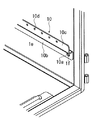
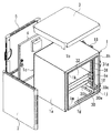
図1は本発明の電気電子機器収納用キャビネット50の第1の実施形態を示す斜視図である。1はキャビネット本体であり、前面1n及び後面1cが開口している箱形形状をしている。このキャビネット本体1の一方の側板1aや、天井面1bには、直射日光によるキャビネット本体1内部の温度上昇を抑制するための遮光板2、3が、それぞれの面を覆うように取り付けられている。
Hereinafter, a preferred embodiment (first embodiment) of the present invention will be described with reference to the drawings.
FIG. 1 is a perspective view showing a first embodiment of a
4はキャビネット本体1の開口している後面1cを覆着する扉であり、開閉自在にキャビネット本体1に取り付けられている。扉4を覆うように、遮光板5が扉4に取り付けられている。
Reference numeral 4 denotes a door that covers the rear surface 1c of the cabinet body 1 that is open, and is attached to the cabinet body 1 so as to be freely opened and closed. A
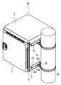
図3に示されるように、キャビネット本体1の開口している前面1nにも、この前面1nを覆着する扉6が、開閉自在にキャビネット本体1に取り付けられ、この扉6を覆うように、遮光板7が取り付けられている。
As shown in FIG. 3, a
図2に、本発明の要部の詳細図を示す。キャビネット本体1の他方の側板1eの内部側には、図2に示されるように、断面形状がクランク形状の剛性レール10が、長手方向を横にし、剛性レール10の一方の面10bと前記側板1eが接するようにして配設されている。なお、本実施形態では、2個の剛性レール10が、高さ方向に一定間隔をおいて、キャビネット本体の側板1eの内部側に配設されている。
FIG. 2 shows a detailed view of the main part of the present invention. On the inner side of the
図2に示されるように、剛性レール10のキャビネット本体1に配設されている面10bの両端よりもやや内側の位置には取付穴10aが形成され、また、キャビネット本体1の前記取付穴10aに対応する位置には、取付穴10aと同軸で殆ど同じ径の貫通穴1fが形成されている。
As shown in FIG. 2, mounting
図3に、電気電子機器収納用キャビネットの前面斜視図を示す。図3に示されるように、キャビネット本体1の側板1eの外部側の、剛性レール10が貼設されている部分には、キャビネット取付金具である断面形状が略L字形状の外部補強金具15が、一方の面15aを上にして配設されている。外部補強金具15の、キャビネット本体1に配設されている面の、前記取付穴10a及び貫通穴1fに対応する位置には、取付穴15bが形成され、これら取付穴10a、貫通穴1f、取付穴15bにより、キャビネット本体1の側板の内部と外部が連通している。
FIG. 3 is a front perspective view of the electrical / electronic equipment storage cabinet. As shown in FIG. 3, an
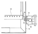
図4に、キャビネット取付金具の取付部分の断面図を示す。図4に示されるように、前記取付穴10a、貫通穴1f、取付穴15bにボルト16を通して、ナット17で締め付けて、剛性レール10や外部補強金具15をキャビネット本体1の側板1eに取り付けている。なお、前記取付穴10a、貫通穴1f、取付穴15bにボルト16を通す方向は、キャビネット本体1の内部側からであっても、外部側からであってもよい。
In FIG. 4, sectional drawing of the attachment part of a cabinet attachment metal fitting is shown. As shown in FIG. 4, the
なお、剛性レール10及び外部補強金具15の、キャビネット本体1の側板1eへの取付方法は、前記方法に限定されず、例えば、取付穴15bの代わりに、ネジ穴を外部補強金具15に形成し、ボルト16をキャビネット本体1の内部側から取付穴10a及び貫通穴1fに通して、外部補強部材15に形成されたネジ穴に締め付けるか、あるいは、取付穴10aを、ネジ穴として剛性レール10に形成し、ボルト16をキャビネット本体1の外部側から取付穴10a及び貫通穴1fに通して、剛性レール10に形成されたネジ穴に締め付けることとしてもよく、キャビネット本体1の側板1eを剛性レール10及び外部補強金具15で挟んで、ボルト16で共締めする構造であればよい。
Note that the method of attaching the
なお、剛性レール10や外部補強金具15を予め、キャビネット本体1に溶接することとしても差し支えない。
Note that no problem even welding the
なお、ボルト16がキャビネト本体1に貫通している部分から、雨水がキャビネット本体1の内部に侵入することを防止するために、ボルト16の座面及び、ナット17の座面にパッキン設けるか、ボルト16を締め付けた後で、キャビネット本体1の貫通部分をシーリング剤でシールすることが好ましい。
In order to prevent rainwater from entering the interior of the cabinet body 1 from the portion where the
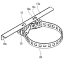
図5に、キャビネット取付金具の詳細図を示す。図3や図5に示されるように、キャビネット取付金具は、外部補強金具15とポール取付金具18とから構成されている。外部補強金具15の上面15aには、一定間隔をおいて、だるま形状の取付穴15cが2個形成されている。図5において、18はポール取付金具であり、このポール取付金具18の上面にはネジ穴18aが2個形成され、外部補強金具15の取付穴15cに、ボルト(図示せず)を通して、前記ネジ穴18aに締め付けて、ポール取付金具18を外部補強金具15に取り付けている。
FIG. 5 shows a detailed view of the cabinet mounting bracket. As shown in FIGS. 3 and 5, the cabinet mounting bracket is composed of an
ポール取付金具18には、ポールや電柱を抱持するポール取付バンド20が設けられて、本発明の電気電子機器収納用キャビネット50をポールや電柱に取り付けている。
The
一方で、電気電子機器収納用キャビネット50を壁に取り付ける場合には、ポール取付金具18の代わりに、キャビネットの取付金具である壁取付金具(図示せず)を用いて、電気電子機器収納用キャビネット50を壁に取り付ける。なお、壁取付金具は外部補強金具を介さずに、キャビネット本体の側板1eをキャビネット内部の剛性レールとで共締めするものとする。
On the other hand, when the electrical / electronic
以下、電気電子機器収納用キャビネット50をポールや壁等の対象物に取り付けるための、外部補強金具15及びポール取付金具18等の取付金具をキャビネット取付金具ということとする。
Hereinafter, the mounting brackets such as the
なお、外部補強金具15とポール取付金具18や壁取付金具等の取付金具を一体構造とした、キャビネット取付金具としても差し支えない。また、キャビネットの取付金具は外部補強金具15を有さず、ポール取付金具18のみからなるものとしてもよい。
It should be noted that the
図2に示されるように、剛性レール10の他方の面10cには、一定間隔をおいて複数の取付ネジ穴10d形成されている。
As shown in FIG. 2, a plurality of mounting screw holes 10 d are formed on the
図1に示されるように、コの字形状のマウントユニット19が、マウントユニット19を貫通するボルトを取付ネジ穴10dに締め込むことにより、剛性レール10に取り付けられている。前述したように、取付ネジ穴10dは、一定間隔をおいて剛性レール10に形成されているので、ボルトを締め付ける取付ネジ穴10dの位置を変えることにより、マウントユニット19を水平方向に自在に、取付位置を変えることができる。
As shown in FIG. 1, the
このマウントユニット19には、HUB等の電子機器が取り付けられる。マウントユニット19に取り付けられる電子機器等がHUBの場合には、このHUBは長手方向を縦にして、マウントユニット19に取り付けられる。なお、マウントユニット19を剛性レール10として構成し、電子機器を直接取り付けることとしても差し支えない。
An electronic device such as a HUB is attached to the
このように、キャビネット本体1の内部に収納される電子機器を、剛性レール10もしくは、剛性レール10に取り付けられるマウントユニット19に取り付けることとしたので、電子機器の荷重が、剛性レール10に作用する。前述したように、キャビネット本体1の側板1eを剛性レール10とキャビネット取付金具で挟んで、ボルト16で共締したので、電子機器の荷重が剛性レール10からキャビネット取付金具に作用し、電子機器の荷重を直接キャビネット取付金具で支えることとなり、前記電子機器の荷重がキャビネット本体1に作用することがないので、キャビネット本体1が変形することがない。
Thus, since the electronic device housed in the cabinet body 1 is attached to the
なお、本実施形態に用いられる、剛性レール10の形状は、クランク形状に限定されず、板状や、断面形状が略L字形状のアングル材や断面形状が略コの字形状のチャンネル材や、角管等であっても差し支えない。
The shape of the
次に第2の実施形態を説明する。この第2の実施形態では、図6に示されるように、L字形状の断面を有する剛性レール30を、キャビネット本体1の側板1eと天井面1b又は底面1gとが交差するそれぞれの角部1h、1jの内部側に溶接により貼設して、キャビネット本体1の角部1h、1jに中空部を形成している。なお、本実施形態では、剛性レール30には、フランジ部30a、30bが設けられ、フランジ部30aをキャビネット本体1の側板1eに、フランジ部30bをキャビネット本体1の底面1gに面をあわせて、溶接されている。また、L字形状の断面を有する剛性レール30は、キャビネット本体1の側板1aと天井面1b又は底面1gとが交差する角部1k、1mの内部側にも溶接により貼設してキャビネットの隅部に中空部を形成している。なお、側板1a側に設けられた剛性レール10は、キャビネットの側板と天井面又は底面との両方に溶接されている必要はなく、コ字形状の断面を有する剛性レールが底面又は天井面のみに溶接されていて、キャビネット本体の隅部に中空部を形成したものであってもよい。
Next, a second embodiment will be described. In the second embodiment, as shown in FIG. 6, a
剛性レール30のフランジ部分30aの両端よりもやや内側の位置には、取付穴30cが形成され、また、キャビネット本体1の前記取付穴30cに対応する位置には、取付穴30cと同軸で殆ど同じ径の貫通穴1fが形成され、これらの、取付穴30c及び貫通穴1fにより、キャビネット本体1の側板の内部と外部が連通している。
A mounting
これらの取付穴30c及び取付穴1fにボルトを通して、実施形態1と同じ方法で、キャビネット取付金具をキャビネット本体1に取り付け、電気電子機器収納用キャビネット50をポールや壁等に取り付けている。
Bolts are passed through the mounting
キャビネットの開口部には、左右一対のマウントレール31、31が上下の剛性レール30の間に設けられている。この、マウントレール31には、一定の間隔おいて、複数の取付ネジ穴31aが形成されている。なお、このマウントレール31の断面形状は、断面形状がコの字形状であっても、板状、断面形状が略L字形状のアングル材や角管であっても差し支えない。
A pair of left and right mounting rails 31 is provided between the upper and lower
キャビネット本体1の内部には、単数もしくは複数の棚板32が、棚板32を貫通するボルトを取付ネジ穴31aに締め込むことにより、左右一対のマウントレール31、31の間に取り付けられている。前述したように、取付ネジ穴31aは、一定間隔をおいてマウントレール31に形成されているので、ボルトを締め付ける取付ネジ穴31aの位置を変えることにより、棚板32を鉛直方向に自在に、取付位置を変えることができる。
Inside the cabinet body 1, one or a plurality of
この棚板32には、HUB等の電子機器が取り付けられる。なお、電子機器を、剛性部材マウントレール31に直接取りけることとしても差し支えない。
An electronic device such as a HUB is attached to the
このように、キャビネット本体1の内部に収納される電子機器を、マウントレール31もしくは、マウントレール31に取り付けられる棚板32に取り付けることとしたので、電子機器の荷重が、直接剛性レール30に作用する。前述したように、キャビネット本体1の側板1eを剛性レール30及びキャビネット取付金具とで挟んで、ボルト16で共締したので、電子機器の荷重が剛性レール30からキャビネット取付金具に作用し、電子機器の荷重を直接キャビネット取付金具で支えることとなり、前記電子機器の荷重がキャビネット本体1に作用することがないので、キャビネット本体1が変形することがない。さらに、断面形状がL字部分を有する剛性レール10をキャビネット本体の側板と天井面又は底面とが交差するそれぞれの角部の内部側に貼設して、キャビネット本体の隅部に中空部を形成したので、最も電子機器等の応力がかかるキャビネットのコーナ部自体を補強することとなり、キャビネット本体1の変形を防止することが可能となる。
As described above, since the electronic device housed in the cabinet body 1 is attached to the mounting
このように、第2の実施形態では、剛性レール30を、少なくともキャビネット本体1の側板1e天井面1b又は底面との、それぞれの角部の内部側に貼設して、チャンネル構造としたので、内部に収納される電子機器のメンテナンス性を向上させるために、キャビネット本体1の前面及び後面1cが開口した構造のキャビネット本体1であっても、剛性を高めることが可能となり、キャビネット本体1の変形を防止することが可能となる。
Thus, in 2nd Embodiment, since the
なお、いずれの実施形態においても、扉4はキャビネット本体1の前面のみに設けられていてもよく、この場合には、剛性レール10や剛性レール30を及びキャビネット取付金具、キャビネット本体1の後面1c側の側板に配設する構造であっても差し支えない。
In any embodiment, the door 4 may be provided only on the front surface of the cabinet body 1. In this case, the
また、キャビネット1本体の底面1gを、ポールや壁等に取付られている支持腕で支えることとしても差し支えない。この場合には、強風で電気電子機器収納用キャビネットが揺れることを防止することが可能となる。
Further, the
以上詳細に説明したように、その内部に電子機器を収納し、キャビネット取付金具を介してポールや壁等に取り付けられる電気電子機器収納用キャビネットにおいて、キャビネット本体1の側板1eを、キャビネット本体1の側板1eの内部側に配設され、前記電子機器の荷重が作用する剛性レール10(30)及びキャビネット本体1の外部側に配設されたキャビネット取付金具で挟んで、ボルト16で共締めをし、キャビネット本体1の内部に収納される電子機器の荷重が、剛性レール10(30)に作用するように構成したので、キャビネット本体1に前記電子機器の荷重が作用することがないので、キャビネット取付金具の取付部分の変形や破損が生じない電気電子機器収納用キャビネットを提供することが可能となった。
As described above in detail, in the electrical / electronic equipment storage cabinet that houses the electronic equipment therein and is attached to a pole, wall, etc. via the cabinet mounting bracket, the
以上、現時点において、もっとも、実践的であり、かつ好ましいと思われる実施形態に関連して本発明を説明したが、本発明は、本願明細書中に開示された実施形態に限定されるものではなく、請求の範囲および明細書全体から読み取れる発明の要旨あるいは思想に反しない範囲で適宜変更可能であり、そのような変更を伴う電気電子機器収納用キャビネットもまた技術的範囲に包含されるものとして理解されなければならない。 Although the present invention has been described above in connection with the most practical and preferred embodiments at the present time, the present invention is not limited to the embodiments disclosed herein. The scope of the invention can be appropriately changed without departing from the gist or concept of the invention that can be read from the claims and the entire specification, and the electrical and electronic equipment storage cabinet accompanying such a change is also included in the technical scope. Must be understood.
1 キャビネット本体
1a 一方の側板
1b 天井面
1c 後面
1e 他方の側板
1f 貫通穴
1g 底面
1h 角部
1j 角部
1k 角部
1m 角部
1n 前面
2 遮光板
3 遮光板
4 扉
5 遮光板
6 扉
7 遮光板
10 剛性レール(第1の実施形態)
10a 取付穴
10b 一方の面
10c 他方の面
10d 取付ネジ穴
15 外部補強金具
15a 一方の面(上面)
15b 取付穴
15c 取付穴
16 ボルト
17 ナット
18 ポール取付金具
18a ネジ穴
19 マウントユニット
20 ポールバンド
30 剛性レール(第2の実施形態)
30a フランジ部
30b フランジ部
30c 取付穴
31 マウントレール
31a 取付ネジ穴
32 棚板
50 電気電子機器収納用キャビネット
1
Claims (2)
少なくともL字断面を有し、前記機器の荷重が作用する剛性レールを、長手方向を横にして、前記キャビネット本体の側板の内面に貼設し、
前記側板外面の前記剛性レールが貼設されている部分に沿わせてキャビネット取付金具を貼設し、
前記側板を、前記剛性レールの面と前記キャビネット取付金具の面とで挟んで、ボルトで共締めをし、
前記機器の荷重が、前記剛性レールから前記キャビネット取付金具に直接作用するように構成したことを特徴とする電気電子機器収納用キャビネット。 In the cabinet for electrical and electronic equipment storage that stores equipment inside and is attached to poles, walls, etc. via cabinet mounting brackets,
A rigid rail that has at least an L-shaped cross section and on which the load of the device acts is placed on the inner surface of the side plate of the cabinet body, with the longitudinal direction being transverse .
Attaching the cabinet mounting bracket along the part where the rigid rail of the side plate outer surface is affixed,
The side plate is sandwiched between the surface of the rigid rail and the surface of the cabinet mounting bracket , and tightened together with bolts,
A cabinet for storing electrical and electronic equipment, wherein a load of the equipment acts directly on the cabinet mounting bracket from the rigid rail.
Priority Applications (1)
| Application Number | Priority Date | Filing Date | Title |
|---|---|---|---|
| JP2006328974A JP4698564B2 (en) | 2006-12-06 | 2006-12-06 | Electrical and electronic equipment storage cabinet |
Applications Claiming Priority (1)
| Application Number | Priority Date | Filing Date | Title |
|---|---|---|---|
| JP2006328974A JP4698564B2 (en) | 2006-12-06 | 2006-12-06 | Electrical and electronic equipment storage cabinet |
Publications (2)
| Publication Number | Publication Date |
|---|---|
| JP2008147210A JP2008147210A (en) | 2008-06-26 |
| JP4698564B2 true JP4698564B2 (en) | 2011-06-08 |
Family
ID=39607092
Family Applications (1)
| Application Number | Title | Priority Date | Filing Date |
|---|---|---|---|
| JP2006328974A Expired - Fee Related JP4698564B2 (en) | 2006-12-06 | 2006-12-06 | Electrical and electronic equipment storage cabinet |
Country Status (1)
| Country | Link |
|---|---|
| JP (1) | JP4698564B2 (en) |
Families Citing this family (4)
| Publication number | Priority date | Publication date | Assignee | Title |
|---|---|---|---|---|
| JP5371000B2 (en) * | 2009-05-29 | 2013-12-18 | 愛知時計電機株式会社 | Electronic equipment mounting structure and equipment mounting adapter |
| JP5416621B2 (en) * | 2010-03-08 | 2014-02-12 | 河村電器産業株式会社 | Box mounting member for prop |
| JP2014203939A (en) * | 2013-04-04 | 2014-10-27 | 日東工業株式会社 | Electronic and electric apparatus housing box with light shielding plate |
| CN114650691A (en) * | 2022-02-24 | 2022-06-21 | 安徽欣创装饰工程有限公司 | Power distribution cabinet |
Family Cites Families (6)
| Publication number | Priority date | Publication date | Assignee | Title |
|---|---|---|---|---|
| JPS5748770U (en) * | 1980-09-05 | 1982-03-18 | ||
| JP2686127B2 (en) * | 1989-01-30 | 1997-12-08 | コクヨ株式会社 | Mounting table |
| JP2999644B2 (en) * | 1993-01-05 | 2000-01-17 | 株式会社日立テレコムテクノロジー | Outdoor installation enclosure |
| JPH1041640A (en) * | 1996-07-24 | 1998-02-13 | Sony Corp | Electronics |
| JP3862343B2 (en) * | 1997-02-24 | 2006-12-27 | 日東工業株式会社 | Mounting method for electrical equipment storage box |
| JP2002084084A (en) * | 2000-09-06 | 2002-03-22 | Komatsu Denki Sangyo Kk | Container of electric apparatus |
-
2006
- 2006-12-06 JP JP2006328974A patent/JP4698564B2/en not_active Expired - Fee Related
Also Published As
| Publication number | Publication date |
|---|---|
| JP2008147210A (en) | 2008-06-26 |
Similar Documents
| Publication | Publication Date | Title |
|---|---|---|
| US9056631B2 (en) | Battery case | |
| JP2015230863A (en) | Power storage device housing | |
| JP5405268B2 (en) | Electrical equipment storage cabinet | |
| JP4698564B2 (en) | Electrical and electronic equipment storage cabinet | |
| CN101593937B (en) | Assembly of an electrical cabinet | |
| JP4949863B2 (en) | How to install the electrical equipment storage box on the wall | |
| JP4632256B2 (en) | Waterproof structure of bus duct and connecting part of bus duct | |
| JP2010267843A (en) | Frame cabinet | |
| JP6462242B2 (en) | Functional component housing, display device, and bathroom | |
| JP6949174B1 (en) | Battery case | |
| JP5946093B2 (en) | Support structure for solar cell module and method for fixing solar cell module using the support structure | |
| JPH0667061B2 (en) | Electric appliance storage board | |
| JP4404711B2 (en) | Electronic device storage box | |
| JP2005033849A (en) | Outdoor board | |
| JP7648323B2 (en) | Electrical equipment storage box and roof cover member | |
| JP2006062859A (en) | Electrical component cover of electric forklift | |
| JP2001177925A (en) | switchboard | |
| CN101299514A (en) | Electrical box and assembly method thereof | |
| JP2012235068A (en) | Auxiliary rail of rack for housing apparatus and rack for housing apparatus | |
| JP2007104763A (en) | Wiring harness wiring structure | |
| KR20080015296A (en) | Supporting device for display device | |
| JP3141276U (en) | Electrical equipment storage box | |
| JP6433171B2 (en) | Functional component mounting structure and bathroom | |
| JP4681330B2 (en) | Elevator hall three-way transportation device | |
| JP4424663B2 (en) | Wiring support member for electrical equipment storage box |
Legal Events
| Date | Code | Title | Description |
|---|---|---|---|
| A621 | Written request for application examination |
Free format text: JAPANESE INTERMEDIATE CODE: A621 Effective date: 20090813 |
|
| A977 | Report on retrieval |
Free format text: JAPANESE INTERMEDIATE CODE: A971007 Effective date: 20101208 |
|
| A131 | Notification of reasons for refusal |
Free format text: JAPANESE INTERMEDIATE CODE: A131 Effective date: 20101214 |
|
| A521 | Request for written amendment filed |
Free format text: JAPANESE INTERMEDIATE CODE: A523 Effective date: 20110210 |
|
| TRDD | Decision of grant or rejection written | ||
| A01 | Written decision to grant a patent or to grant a registration (utility model) |
Free format text: JAPANESE INTERMEDIATE CODE: A01 Effective date: 20110301 |
|
| A61 | First payment of annual fees (during grant procedure) |
Free format text: JAPANESE INTERMEDIATE CODE: A61 Effective date: 20110301 |
|
| R150 | Certificate of patent or registration of utility model |
Ref document number: 4698564 Country of ref document: JP Free format text: JAPANESE INTERMEDIATE CODE: R150 |
|
| LAPS | Cancellation because of no payment of annual fees |