JP4698552B2 - Parting lock device and mold device provided with the device - Google Patents
Parting lock device and mold device provided with the device Download PDFInfo
- Publication number
- JP4698552B2 JP4698552B2 JP2006306766A JP2006306766A JP4698552B2 JP 4698552 B2 JP4698552 B2 JP 4698552B2 JP 2006306766 A JP2006306766 A JP 2006306766A JP 2006306766 A JP2006306766 A JP 2006306766A JP 4698552 B2 JP4698552 B2 JP 4698552B2
- Authority
- JP
- Japan
- Prior art keywords
- mold
- lock
- parting
- air
- rod
- Prior art date
- Legal status (The legal status is an assumption and is not a legal conclusion. Google has not performed a legal analysis and makes no representation as to the accuracy of the status listed.)
- Active
Links
Images


Landscapes
- Moulds For Moulding Plastics Or The Like (AREA)
- Injection Moulding Of Plastics Or The Like (AREA)
Description
この発明は、3プレート金型や2段構造金型に採用可能なパーティングロック装置とパーティングロック装置を備えた金型装置に関するものである。 The present invention relates to a parting lock device that can be employed in a three-plate mold or a two-stage structure mold, and a mold device including the parting lock device.
一般に3プレート金型と称されてる金型は、金型のパーティングラインとは別のもう一つの平面にランナを配置した構造からなる。また2段構造金型はもう一つの平面もパーティングラインとして金型を配置した構造からなる。その何れの金型においても、型開は固定盤側のランナープレート又は金型(以下第一金型という)と中間位置の金型(以下第二金型という)の型開を先行し、次に第二金型と可動盤側の金型(以下第三金型という)の型開を行っている。 A mold generally called a three-plate mold has a structure in which a runner is arranged on another plane different from the parting line of the mold. The two-stage mold has a structure in which the mold is arranged on the other plane as a parting line. In any of these molds, the mold opening precedes the mold opening of the runner plate or mold on the fixed platen side (hereinafter referred to as the first mold) and the mold at the intermediate position (hereinafter referred to as the second mold). In addition, the second die and the movable platen die (hereinafter referred to as the third die) are opened.
第一金型と第二金型の型開(以下第一型開という)は、第二金型と第三金型とを型閉状態で移動して、第二金型がピンやリンクなどにより制限位置に停止する所まで行われ、第二金型と第三金型の型開(以下第二型開という)は、第三金型をさらに移動して行っている。この第二型開までの型閉の保持は、第二金型と第三金型により形成されたキャビティ内に射出充填された樹脂の型開抵抗をもって行っている。このため樹脂の充填状態によっては型開抵抗が不十分となって、第三金型が第二金型を停止位置まで引っ張切れずに、第一型開の途中で第二型開が始まって第二金型の置き去りが生ずることがある。このため第一型開が中途半端で終わって第一金型と第二金型とにより成形されたランナなどの成形品が金型間に残り、次の成形に支障を来すことがある。 The mold opening of the first mold and the second mold (hereinafter referred to as the first mold opening) is performed by moving the second mold and the third mold in a closed state, and the second mold is moved to a pin or a link. Thus, the second mold and the third mold are opened (hereinafter referred to as second mold opening) by further moving the third mold. The holding of the mold closed until the second mold is opened is performed by the mold opening resistance of the resin injected and filled in the cavity formed by the second mold and the third mold. For this reason, depending on the resin filling state, the mold opening resistance becomes insufficient, and the second mold opening is started in the middle of the first mold opening without the third mold pulling the second mold to the stop position. The second mold may be left behind. For this reason, the first mold opening ends halfway, and a molded product such as a runner molded by the first mold and the second mold remains between the molds, which may hinder the next molding.
このような型開順序を常に確実となす手段として、第二金型と第三金型のパーティングラインを機械的手段によりロックして型閉状態を保持し、第一金型と第二金型の型開完了時にロックを解除して、第一型開から第二型開への移行することが行われている。この機械的なロック手段としては、第二金型と第三金型の何れか一方の側面に取付けた係止部材と、他方の金型側面に取付けた一対の係止部片とを金型の型閉力をもって係合するものが知られている。 As a means for always ensuring such a mold opening order, the parting lines of the second mold and the third mold are locked by mechanical means to keep the mold closed, and the first mold and the second mold When the mold opening of the mold is completed, the lock is released to shift from the first mold opening to the second mold opening. As the mechanical locking means, a locking member attached to one side surface of the second mold or the third mold and a pair of locking part pieces attached to the other mold side surface are molded. The one that engages with the mold closing force is known.
また固定型の側面に突設したピンと係合する係止レバーを、可動型の側面に回動自在に設け、その係止レバーをエアシリンダにより回動して、レバー先端とピンとの係合により、または3プレート式金型ではさらにランナストリッパプレートのガイド溝との係合によりパーティングロックを行っている。また可動型と固定型の上部をエアシリンダにより上下するピンにより連結してパーティングロックを行っているものもある。
上記従来の係止部材と係止部片とを金型の型閉力をもって係止するロック手段を、金型間の異物を型閉抵抗から検出して型閉を停止する装置を備えた金型に採用すると、ロック時に生ずる型閉抵抗を異物による型閉抵抗として誤検出することから、型閉抵抗による異物検出装置を備えた型締装置には採用し難く、また型閉力による係止では、反復作動による係止部の摩耗が早いので、メンテナンス期間が短いなどの課題を有する。 A lock means for locking the conventional locking member and the locking piece with the mold closing force of the mold, and a mold having a device for detecting foreign matter between the molds from the mold closing resistance and stopping the mold closing. When used in a mold, the mold closing resistance generated at the time of locking is erroneously detected as a mold closing resistance due to foreign matter, so it is difficult to adopt it in a mold clamping device equipped with a foreign matter detection device based on mold closing resistance, and locking due to mold closing force Then, since the wear of the locking portion due to repetitive operation is fast, there are problems such as a short maintenance period.
またパーティングロックを型閉力によらずエアシリンダにより行うロック手段では、型閉抵抗による異物検出装置の障害となることはないが、エアシリンダにより可動型の側面に設けた係止レバーを回動して、固定型の側面に突設したピンに係合していることから、型閉途中でエアシリンダが誤作動すると、係止レバーが回動してピン前にレバー先端が位置し、3プレート式金型ではガイドピンがガイド溝からずれるなどして型閉が行えなくなり、加えて係止レバーの折損及び金型の損傷いう課題を有する。また可動型と固定型の上部をエアシリンダにより上下するピンにより連結してパーティングロックを行う場合も同様で、誤作動による型閉のピンの突出により該ピンの折損及び金型の損傷を来す虞があるので採用し難い課題を有する。 In addition, the locking means that performs the parting lock with the air cylinder regardless of the mold closing force does not obstruct the foreign object detection device due to the mold closing resistance, but the locking lever provided on the side surface of the movable mold is rotated by the air cylinder. Because it moves and engages with a pin protruding from the side of the fixed mold, if the air cylinder malfunctions in the middle of mold closing, the locking lever rotates and the lever tip is positioned in front of the pin. In the three-plate mold, the guide pin is displaced from the guide groove so that the mold cannot be closed. In addition, there is a problem that the locking lever is broken and the mold is damaged. Similarly, when the parting lock is performed by connecting the upper part of the movable mold and the fixed mold with a pin that moves up and down with an air cylinder, the protrusion of the mold closing pin due to malfunction causes damage to the pin and the mold. There is a problem that is difficult to adopt.
この発明は上記課題を解決するために考えられたものであって、その目的は、金型のパーティングロックにエアを採用し、そのエアを型閉状態でのみエアシリンダに供給できるように構成して、金型相互のパーティングロックをエア作動のロックロッドと該ロックロッドと直交位置するロックプレートの嵌合により行えるようにした新たなパーティングロック装置とその装置を備えた金型装置とを提供することにある。 The present invention has been conceived in order to solve the above-described problems, and an object of the present invention is to employ air in a mold parting lock so that the air can be supplied to an air cylinder only when the mold is closed. And a new parting lock device which can perform a parting lock between molds by fitting an air-operated lock rod and a lock plate orthogonal to the lock rod, and a mold device equipped with the device. Is to provide.
上記目的によるこの発明のパーティングロック装置は、リターンスプリングを備えるエアシリンダと、そのエアシリンダのピストンと一体のロックロッドと、本体側方からエアシリンダのピストン加圧側に穿設したエア供給路と、前記ロックロッドの先端が進出可能な収容溝とを有する四辺形の本体ブロックと、上記本体ブロックとの当接側面を有し、その当接側面から突出していると共に、前記エア供給路を穿設した前記本体ブロックの所定側面に前記当接側面を当接させると、前記収容溝に入り込み、上記ロックロッドと直交位置状態となって該ロックロッドの先端と係合可能なロックプレートと、当該当接時に上記エア供給路と連通するエア通路とを有する四辺形の当接ブロックとを具備するというものである。 The parting lock device of the present invention according to the above object includes an air cylinder having a return spring, a lock rod integrated with a piston of the air cylinder, an air supply path drilled from the side of the main body to the piston pressure side of the air cylinder, The lock rod has a quadrilateral main body block having a receiving groove into which the front end of the lock rod can be advanced, and a contact side surface of the main body block. The main body block protrudes from the contact side surface and pierces the air supply path. If the abut the abutment side in a predetermined side of the set and said main body block, enters the receiving groove, tip and engageable with the lock plate of the lock rod is perpendicular position state and the lock rod, the when contact is that includes a contact block quadrilateral having an air passage communicating with the air supply passage.
また上記エアシリンダは、上記リターンスプリングが位置するシリンダ内端にロッド孔を有し、そのロッド孔の近傍のシリンダに上記エア供給路とは異なる本体側方から穿設したエア吸排路を有するというものであり、また上記ロックロッドは、上記エアシリンダのピストンと一体で先端側面がテーパー面に形成され、そのロックロッドが臨む上記ロックプレートの上面をロッド先端と嵌合するテーパー凹部に形成してなる、というものである。 Further, the air cylinder has a rod hole at the inner end of the cylinder where the return spring is located, and a cylinder near the rod hole has an air intake / exhaust passage drilled from the side of the main body different from the air supply passage. Further, the lock rod is formed integrally with the piston of the air cylinder, the tip side surface is formed into a tapered surface, and the upper surface of the lock plate facing the lock rod is formed into a tapered recess that fits the rod tip. It will be.
また上記エア供給路は、本体側面の開口路端に先端が該側面から突出した開弁用ピンを有し、上記エア通路は開弁用ピンに押圧されて開弁するチェックバルブを当接側面の開口路端内に有する、というものである。 The air supply path has a valve-opening pin whose tip protrudes from the side of the opening on the side surface of the main body, and the air passage contacts a check valve that is opened by being pressed by the valve-opening pin. It is said that it has in the opening path end.
この発明の金型装置は、上記パーティングロック装置の本体ブロックと当接ブロックとを、一対の金型の型閉により上記ロックロッドの先端に上記ロックプレートが位置し、かつ金型の型閉に同時する両ブロックの当接後に、上記エア通路から供給されるエアにより上記ピストンと共にロックロッドが作動し、該ロックロッドとロックプレートとの係合によるパーティングロックが生ずるように、一対の金型のいずれか一方の金型と他方の金型に、それぞれパーティング面に沿って設置してなる、というものである。 The mold apparatus according to the present invention includes a body block and a contact block of the parting lock device, wherein the lock plate is positioned at the tip of the lock rod by closing a pair of molds, and the mold is closed. At the same time, the lock rod is operated together with the piston by the air supplied from the air passage so that a parting lock is generated by the engagement between the lock rod and the lock plate. Each of the molds is installed along the parting surface on one of the molds and the other mold.
また上記金型は、固定盤側の第一金型と中間部位の第二金型と可動盤側の第三金型とからなり、その第二金型と第三金型とに上記パーティングロック装置の上記本体ブロックと上記当接ブロックとを、それぞれパーティング面に沿って設置してなる、というものである。 The mold includes a first mold on the stationary platen side, a second mold on the intermediate portion, and a third mold on the movable platen side, and the parting is performed on the second mold and the third mold. The main body block and the abutment block of the locking device are each installed along the parting surface.
上記構成のパーティングロック装置では、本体ブロック内のエアシリンダへのエアの供給を、本体ブロックとは別体の当接ブロックから行えるようにしたので、常にパーティングロック作動が型閉後となり、型閉完了前の誤作動によるパーティングロック作動は生じないことから、型閉途中での作動によるロックロッドの折損や金型の損傷を防止することができ、またエア作動のロックロッドとそれに直交位置するロックプレートとの嵌合では、型閉抵抗に影響を与えることはないので、型閉抵抗による異物検出装置を備えた型締装置の金型に採用することができる。 In the parting lock device having the above configuration, since the air supply to the air cylinder in the main body block can be performed from the contact block separate from the main body block, the parting lock operation is always after the mold is closed, Since there is no parting lock operation due to malfunction before mold closing is completed, breakage of the lock rod and damage to the mold due to operation during mold closing can be prevented, and air operated lock rod and orthogonal to it Since the fitting with the lock plate positioned does not affect the mold closing resistance, it can be employed in a mold of a mold clamping device provided with a foreign matter detecting device based on the mold closing resistance.
また上記パーティングロック装置を、中間部位の第二金型と可動盤側の第三金型とにわたり備えた3プレート式金型では、型閉直後から型開開始直前までに当接ブロック側から本体ブロック内のエアシリンダにエアを供給するだけでパーティングロックができ、ロック解除もエアパージするだけでよいので操作が簡単に済む。また第二金型と第三金型をパーティングロックした状態で第一型開が行われるので、第一型開の途中で第二型開が生ずることがなく、第二金型が制限位置に停止する間際にエアシリンダのパージングを行うだけで型開が第一型開から第二型開にスムーズに移行するので、移行の際に第二金型が制限ピンのストッパー及びガイドピンのピンヘッドに衝突して金型が損傷するようなこともない。 In the case of a three-plate mold provided with the above parting lock device between the second mold at the intermediate portion and the third mold at the movable platen side, the contact block side is immediately after the mold is closed until the mold is opened. The parting lock can be performed simply by supplying air to the air cylinder in the main body block, and the operation can be easily performed because it is only necessary to perform air purge for unlocking. In addition, since the first mold is opened while the second mold and the third mold are parting-locked, the second mold is not opened in the middle of the first mold opening, and the second mold is in the restricted position. Since the mold opening smoothly transitions from the first mold opening to the second mold opening just by purging the air cylinder just before stopping, the second mold moves the stopper pin of the limit pin and the pin head of the guide pin during the transition The mold will not be damaged by collision.
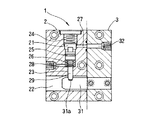
図中1はパーティングロック装置で、本体ブロック2と当接ブロック3とからなり、その両方は同一肉厚で互いに側面を接して1つの形態をなす四辺形のブロックからなる。
In the figure,
上記本体ブロック2は、側面と平行に穿設して形成したエアシリンダ21と、そのエアシリンダ21と壁部を隔てて直交位置するロックプレートの収容溝22とを内部に有し、その壁部にロッド孔23がシリンダ内端から収容溝22に穿設してある。
The
上記エアシリンダ21は穿穴の開口端を蓋部材24により密閉して形成され、内部にピストン25とリターンスプリング26とを有する。また本体側方からピストン加圧側に穿設したエア供給路27と、そのエア供給路27とは異なる本体側方からロッド孔23の近傍のシリンダに穿設したエア吸排路28とを有する。このエア吸排路28はロッド孔23を兼用として省略することができる。
The
上記ピストン25は、先端側面をテーパー面に形成したロックロッド29と一体で、ロックロッド29を上記ロッド孔23に挿入して摺動自在に設けてある。ロックロッド29は先端が上記収容溝22に突出しないようにリターンスプリング26により保持されている。
The
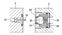
上記当接ブロック3は、上記本体ブロック2との当接側面から突出して上記ロックロッド29の先端部と直交位置するロックプレート31を、ブロック側面の上記収容溝22の対向位置に有し、本体ブロック2との当接時に上記エア供給路27と連通するエア通路32を、ブロック内にエア供給路27よりも大径に穿設して有する。
The
上記ロックプレート31は、プレート側面を当接ブロック3の側面内に嵌合してボルト止めしてあり、先端部の上面にはロックロッド29の先端が嵌合する凹所31aが形成してある。この凹所31aの前後面はロッド先端と適合するテーパー面に形成してある。
The
上記構成のパーティングロック装置1では、図1に示すように、本体ブロック2と当接ブロック3とが離れた状態にあると、エア供給路27とエア通路32とが離れてエアシリンダ21の加圧側は無圧状態で、ピストン25はロックロッド29と共にリターンスプリング26により上方に保持されて、ロッド先端がロッド孔内に収まっている。
In the
図2に示すように、本体ブロック2と当接ブロック3とが側面を互いに接した状態では、ロックプレート31がロックロッド29の先端直下に凹所31aが位置するところまで収容溝22に入り込み、またエア供給路27とエア通路32が互いの開口端を接して連通するようになる。かかる状態においてコンプレッサにより圧搾して高圧タンクに蓄えたエアをエア通路32からエア供給路27に供給すると、ピストン25が加圧されてリターンスプリング26を圧縮する。これによりロックロッド29は収容溝22に突き出て先端直下のロックプレート31の凹所31aと先端が嵌合し、ロックプレート31と共に本体ブロック2と当接ブロック3とを互いに拘束するようになる。
As shown in FIG. 2, in a state where the
したがって、本体ブロック2と当接ブロック3とをパーティング面に沿って側面に設置した一対の金型では、エアの圧力によりパーティングがロックされて型閉状態が保持され、その保持はブロック相互の間からエアがパージされてピストン25がリターンスプリング26により復帰するまで保持される。
Therefore, in the pair of molds in which the
図4は、上記エア通路32にバルブを設けた実施形態を示すもので、上記エア供給路27の本体ブロック2の当接側面に開口した路端に、当接側面から突出する長さの開弁用ピン33を設け、その開弁用ピン33により開弁するチェックバルブ34を上記エア通路32の路端内に設けたもので、そのチェックバルブ34はボール弁35を内側のバネ部材36により弁座37に弾圧して閉弁状態を維持する通常構造のものからなる。
FIG. 4 shows an embodiment in which a valve is provided in the
このチェックバルブ34により開口路端を常時閉鎖したたエア通路32では、通路内をエアにより常時加圧しておくことができる。これにより本体ブロック2と当接ブロック3との接近に伴うブロック相互の間隔の減少により、開弁用ピン33がボール弁35にタッチし、さらに型閉力によりボール弁35が押し込められてエアがブロック間の隙間に流出する。このエアの流出はブロック相互が当接するまでの僅かな時間で、当接と同時にエアはエア供給路27に流入してピストン25を加圧し、ロックロッド29をロックプレート31の上面に突き出す。したがって、ブロック相互の当接とロック作動とが同時に行えるようになる。
In the
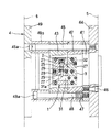
図5以下は、上記パーティングロック装置1を備えた3プレート金型4の1例を示すもので、41は第一金型、42は中間部位の第二金型、43は第三金型である。第一金型41は型取付板5に固定した制限ピン45を片側を挿通し、他側を可動ピン46により型取付板5に取付けて該型取付板の板面に接離自在に設けられている。
FIG. 5 and subsequent figures show an example of a three-plate mold 4 provided with the above-mentioned
上記第二金型42は両側を上記制限ピン45とピン周囲にバネ部材47を設けて第一金型41に固定したガイドピン48とに挿通支持して、制限ピン45の先端のストッパー45aとガイドピン48のピンヘッド48aに接するところまで移動自在に型開するように、第一金型41に重ねて設けられている。また上記第三金型43は型取付板49の板面に設けた台座49aに取付けて設けられており、この第三金型43と台座49aの両側には上記制限ピン45とガイドピン48の挿通孔が設けてある。
The
第二金型42と第三金型43の側面には上記パーティングロック装置1が、第二金型側に当接ブロック3を、第三金型側に本体ブロック2をボルトにより止着して取付けてある。本体ブロック2と当接ブロック3のそれぞれは、当接側面を金型のパーティング面と同一にして、上記エア供給路27とエア通路32とが型閉時の当接により連通し、また本体ブロック2の収容溝22にロックプレート31が収まるように高さ位置を同じくして対設してある。
On the side surfaces of the
上記金型装置は、第一金型41を型締装置(図は省略)の固定盤5に型取付板44をもって取付け、第三金型43を可動盤6に型取付板49をもって取付けている。またエア通路32とエア吸排路28には、図では省略しているが圧搾エアの供給パイプとエア吸排用のパイプが接続され、必要に応じて圧搾エアをエアタンクからエア通路32に供給できるようにしてある。
In the mold apparatus, the
可動盤6による金型の型閉動作は、通常のごとく先ず可動盤6の前進移動により第三金型43と中間位置に型開した第二金型42とが型閉する。この型閉に伴いパーティング面から突出している上記ロックプレート31が、上述のように本体ブロック2の収容溝22に内に入り込み、両金型がパーティング面を接して型閉したときに、プレート先端部の上面に形成した凹所31aが、上記ロックロッド29の先端直下に位置する。また両金型の側面の上記本体ブロック2と当接ブロック3とが互いに接して、エア供給路7とエア通路32が連通する。
As usual, the mold closing operation of the mold by the
したがって、型開状態ではエア供給路7とエア通路32の連通はないので、型閉途中でエアをエア通路に圧送しても、そのエアは本体ブロック2と当接ブロック3との隙間に流出して大気中に放出され、エア供給路27に流入することはないから、誤作動でエア供給が生じてもパーティングロックは行われない。
Accordingly, since the air supply path 7 and the
次に可動盤6の前進移動により第一金型41と型閉した第二金型42が、第一金型41を型取付板41に押圧して型閉し、全ての金型の型閉が終了する。この型閉の後に可動盤6による型締が行われて、溶融樹脂が第一金型41から第二金型42と第三金型43との間に形成されたキャビティ(図は省略)に射出充填され、樹脂の冷却後に型開となる。
Next, the
上記パーティングロック装置1による第二金型42と第三金型43のパーティングロックは、型閉直後から型開直前までの間(好ましくは型開1sec程前)に行われる。樹脂の射出充填が完了すると、図示しないエア回路がONして圧搾エアがエアタンクから供給され、エアはエア通路32からエア供給路27を通ってエアシリンダ21の加圧側に圧入され、ピストン25を加圧する。
The parting lock of the
図6に示すように、ピストン25はリターンスプリング26に抗してロックロッド29と共に前進移動し、ロッド先端がロッド孔23から突き出て凹所31aと嵌合し、ロックプレート31との連結により第二金型42と第三金型43のパーティングが第二金型42が受ける引張力により離れないようにロックする。このパーティングロックはエアによりピストン25が加圧されているあいだ保持される。
As shown in FIG. 6, the
可動盤6が後退移動すると、先ず第一金型41から第二金型42が離れて第一型開となる。この第一型開は第二金型42が制限ピン45のストッパー45aとガイドピン48のピンヘッド48aに接して停止するまで維持される。パーティングロックされていない場合には、キャビティの樹脂の充填圧力の不十分さや引張抵抗の変化等から第二金型42が停止位置に達するまでの間に第二型開がが生ずることがあるが、パーティングロックではそのような事態が防止され、常に第一型開が第二金型42の停止位置まで維持される。
When the
第二型開は第二金型42の停止により、可動盤6の後退による引張力が第三金型43に作用して生ずるものであるから、停止時にもパーティングロックされた状態にあると引張力が第二金型42にも作用して、第二金型42が上記ストッパ45a及びピンヘッド48aと衝突し、その衝撃により金型が損傷することがあるので、停止直前(例えば5〜6mm前)にエア供給を停止してエア回路をエアパージに切り換える。
The second mold opening is caused by the
このエアパージにより、第二金型42がストッパ45a及びピンヘッド48aに衝突する前に、ピストン25と共にロックロッド29がリターンスプリングにより復帰し、ロックロッド29とロックプレート31との嵌合による第二金型42と第三金型43の拘束が解除されて、停止した第二金型42から第三金型43が離れて第二型開が、図5に示す型開位置までスムーズに行われる。
By this air purge, before the
またエアパージが遅れたときには、ロックロッド29の先端と凹所31aがテーパー面に形成されていることから、第三金型43に掛かる引張力によりロッド先端にテーパー面に沿った押上力が生ずるようになる。この押上力によりピストン25が加圧側のエアを加圧する。圧搾されたエアは油圧と異なって加圧により圧縮できるので、その圧縮分だけロックロッド29が第三金型43とともに型開方向に横ずれする。これにより金型相互が接していたパーティング面に隙間が生じ、この隙間からエアシリンダ21のエアがリークして加圧側の圧力が除かれてゆき、ロックロッド29と第三金型43の横ずれが進行する。このようなことからエアパージが遅れても大きな衝撃を起こすことなく、第一型開から第二型開の移行がスムーズに行われるようになる。
When the air purge is delayed, the tip of the
1 パーティングロック装置
2 本体ブロック
21 エアシリンダ
22 ロックプレートの収容溝
23 ロッド孔
25 ピストン
26 リターンスプリング
27 エア供給路
28 エア吸排路
29 ロックロッド
3 当接ブロック
31 ロックプレート
31a 嵌合用の凹所
32 エア通路
33 開弁用ピン
34 チェックバルブ
4 3プレート金型
41 第一金型
42 第二金型
43 第三金型
45 制限ピン
45a ストッパー
48 ガイドピン
48a ピンヘッド
DESCRIPTION OF
Claims (6)
上記本体ブロックとの当接側面を有し、その当接側面から突出していると共に、前記エア供給路を穿設した前記本体ブロックの所定側面に前記当接側面を当接させると、前記収容溝に入り込み、上記ロックロッドと直交位置状態となって該ロックロッドの先端と係合可能なロックプレートと、当該当接時に上記エア供給路と連通するエア通路とを有する四辺形の当接ブロックとを具備することを特徴とするパーティングロック装置。 An air cylinder having a return spring, a lock rod integrated with the piston of the air cylinder, an air supply path drilled from the side of the body to the piston pressure side of the air cylinder, and a receiving groove in which the tip of the lock rod can be advanced a body block quadrilateral with bets,
The housing groove has a contact side surface with the main body block, protrudes from the contact side surface, and abuts the contact side surface with a predetermined side surface of the main body block having the air supply passage formed therein. to enter, tip and engageable with the lock plate of the lock rod is perpendicular position state and the lock rod, a contact block quadrilateral having an air passage for the air supply passage and communicating at the abutment A parting lock device comprising:
Priority Applications (1)
| Application Number | Priority Date | Filing Date | Title |
|---|---|---|---|
| JP2006306766A JP4698552B2 (en) | 2006-11-13 | 2006-11-13 | Parting lock device and mold device provided with the device |
Applications Claiming Priority (1)
| Application Number | Priority Date | Filing Date | Title |
|---|---|---|---|
| JP2006306766A JP4698552B2 (en) | 2006-11-13 | 2006-11-13 | Parting lock device and mold device provided with the device |
Publications (2)
| Publication Number | Publication Date |
|---|---|
| JP2008119953A JP2008119953A (en) | 2008-05-29 |
| JP4698552B2 true JP4698552B2 (en) | 2011-06-08 |
Family
ID=39505246
Family Applications (1)
| Application Number | Title | Priority Date | Filing Date |
|---|---|---|---|
| JP2006306766A Active JP4698552B2 (en) | 2006-11-13 | 2006-11-13 | Parting lock device and mold device provided with the device |
Country Status (1)
| Country | Link |
|---|---|
| JP (1) | JP4698552B2 (en) |
Families Citing this family (9)
| Publication number | Priority date | Publication date | Assignee | Title |
|---|---|---|---|---|
| US8061005B2 (en) * | 2009-03-13 | 2011-11-22 | Carefusion 303, Inc. | Method for employing quick change injection molding tooling |
| CN103737961B (en) * | 2013-12-10 | 2015-10-21 | 北京理工大学 | Shifting formwork locked mode integral type die cylinder structure |
| JP6390367B2 (en) | 2014-11-13 | 2018-09-19 | 株式会社デンソー | Mold and mold setup method |
| DE112015006871T5 (en) | 2015-09-02 | 2018-05-24 | Aiyuki Giken Co., Ltd. | CLOSING DEVICE AND THIS USE OF INJECTION MOLDING |
| JP6134776B1 (en) * | 2015-12-23 | 2017-05-24 | 美濃工業栃木株式会社 | Die casting mold |
| JP2018069704A (en) * | 2016-11-04 | 2018-05-10 | 大和化成工業株式会社 | apparatus |
| CN108214355B (en) * | 2018-01-20 | 2024-02-02 | 梵利特智能科技(苏州)有限公司 | Card positioning and placing mechanism |
| CN108621471B (en) * | 2018-07-13 | 2024-04-09 | 苏州劲翔电子科技有限公司 | Safety lock for push-open switch of product mould |
| CN112935220A (en) * | 2021-01-06 | 2021-06-11 | 安徽将煜电子科技有限公司 | Die-casting machine clamping mechanism |
Family Cites Families (5)
| Publication number | Priority date | Publication date | Assignee | Title |
|---|---|---|---|---|
| JPS5474758U (en) * | 1977-11-08 | 1979-05-28 | ||
| JPH03106548A (en) * | 1989-09-20 | 1991-05-07 | Eguchi Diecast Kk | Die casting apparatus and product |
| JP2871663B2 (en) * | 1997-01-17 | 1999-03-17 | 平道 馬渕 | Mold and mold opening and closing device |
| JPH1177762A (en) * | 1997-09-03 | 1999-03-23 | Sekisui Chem Co Ltd | Injection molding die and method of manufacturing injection molded product |
| JP3761690B2 (en) * | 1997-10-09 | 2006-03-29 | 勝利 西村 | Automatic mold opening and closing device |
-
2006
- 2006-11-13 JP JP2006306766A patent/JP4698552B2/en active Active
Also Published As
| Publication number | Publication date |
|---|---|
| JP2008119953A (en) | 2008-05-29 |
Similar Documents
| Publication | Publication Date | Title |
|---|---|---|
| JP4698552B2 (en) | Parting lock device and mold device provided with the device | |
| US6679698B2 (en) | Die clamping apparatus | |
| JP5143616B2 (en) | Mold for plastic injection molding and valve applied thereto | |
| WO2014099456A1 (en) | Molding tool for producing a component in a gas-assisted injection molding process | |
| JPS62151258A (en) | Venting device for die | |
| KR950009716B1 (en) | Nozzle device for injection molding | |
| KR20240022096A (en) | A ejecting device for die casting system | |
| US20040099401A1 (en) | Diecasting machine | |
| JP2014213372A (en) | Degassing device for die casting | |
| JP2005161669A (en) | Molding machine | |
| KR200418297Y1 (en) | Injection mold with air mill pin device | |
| JP2007296773A (en) | Slide core device for multicolor molding | |
| KR100541746B1 (en) | Manufacturing method of mold injection product having porous pinhole | |
| JP2006026698A (en) | Pressure measuring device in cavity of die casting mold | |
| JPH11291013A (en) | Gas venting device for die used in die casting | |
| JPH11129303A (en) | Tie bar locking method and device for compound direct pressure type mold clamping device | |
| JP2010052322A (en) | Injection molding machine | |
| JPH08336865A (en) | Injection molding gate sealing mechanism | |
| JPS606262A (en) | Gas venting device for die casting | |
| CN100423928C (en) | Injection molding machine clamping cylinder with hydraulic safety device | |
| JPH06262652A (en) | Injection molding method and injection molding die | |
| JP4702857B2 (en) | Angular pin drive slide type locking device | |
| JPH049077Y2 (en) | ||
| KR101902157B1 (en) | Power Locking Device for Die Clamping | |
| JPH05131498A (en) | Injection molding nozzle |
Legal Events
| Date | Code | Title | Description |
|---|---|---|---|
| A621 | Written request for application examination |
Free format text: JAPANESE INTERMEDIATE CODE: A621 Effective date: 20080428 |
|
| RD04 | Notification of resignation of power of attorney |
Free format text: JAPANESE INTERMEDIATE CODE: A7424 Effective date: 20100131 |
|
| A977 | Report on retrieval |
Free format text: JAPANESE INTERMEDIATE CODE: A971007 Effective date: 20101019 |
|
| A131 | Notification of reasons for refusal |
Free format text: JAPANESE INTERMEDIATE CODE: A131 Effective date: 20101102 |
|
| A521 | Request for written amendment filed |
Free format text: JAPANESE INTERMEDIATE CODE: A523 Effective date: 20101221 Free format text: JAPANESE INTERMEDIATE CODE: A821 Effective date: 20101221 |
|
| RD02 | Notification of acceptance of power of attorney |
Free format text: JAPANESE INTERMEDIATE CODE: A7422 Effective date: 20101221 |
|
| TRDD | Decision of grant or rejection written | ||
| A01 | Written decision to grant a patent or to grant a registration (utility model) |
Free format text: JAPANESE INTERMEDIATE CODE: A01 Effective date: 20110201 |
|
| A61 | First payment of annual fees (during grant procedure) |
Free format text: JAPANESE INTERMEDIATE CODE: A61 Effective date: 20110301 |
|
| R150 | Certificate of patent or registration of utility model |
Ref document number: 4698552 Country of ref document: JP Free format text: JAPANESE INTERMEDIATE CODE: R150 |
|
| R250 | Receipt of annual fees |
Free format text: JAPANESE INTERMEDIATE CODE: R250 |
|
| R250 | Receipt of annual fees |
Free format text: JAPANESE INTERMEDIATE CODE: R250 |
|
| R250 | Receipt of annual fees |
Free format text: JAPANESE INTERMEDIATE CODE: R250 |
|
| R250 | Receipt of annual fees |
Free format text: JAPANESE INTERMEDIATE CODE: R250 |
|
| R250 | Receipt of annual fees |
Free format text: JAPANESE INTERMEDIATE CODE: R250 |
|
| R250 | Receipt of annual fees |
Free format text: JAPANESE INTERMEDIATE CODE: R250 |