JP4697293B2 - Water treatment equipment - Google Patents
Water treatment equipment Download PDFInfo
- Publication number
- JP4697293B2 JP4697293B2 JP2008310952A JP2008310952A JP4697293B2 JP 4697293 B2 JP4697293 B2 JP 4697293B2 JP 2008310952 A JP2008310952 A JP 2008310952A JP 2008310952 A JP2008310952 A JP 2008310952A JP 4697293 B2 JP4697293 B2 JP 4697293B2
- Authority
- JP
- Japan
- Prior art keywords
- water
- flow rate
- channel
- water channel
- purified
- Prior art date
- Legal status (The legal status is an assumption and is not a legal conclusion. Google has not performed a legal analysis and makes no representation as to the accuracy of the status listed.)
- Expired - Fee Related
Links
Images
Classifications
-
- C—CHEMISTRY; METALLURGY
- C02—TREATMENT OF WATER, WASTE WATER, SEWAGE, OR SLUDGE
- C02F—TREATMENT OF WATER, WASTE WATER, SEWAGE, OR SLUDGE
- C02F1/00—Treatment of water, waste water, or sewage
- C02F1/46—Treatment of water, waste water, or sewage by electrochemical methods
- C02F1/461—Treatment of water, waste water, or sewage by electrochemical methods by electrolysis
- C02F1/46104—Devices therefor; Their operating or servicing
-
- C—CHEMISTRY; METALLURGY
- C02—TREATMENT OF WATER, WASTE WATER, SEWAGE, OR SLUDGE
- C02F—TREATMENT OF WATER, WASTE WATER, SEWAGE, OR SLUDGE
- C02F2201/00—Apparatus for treatment of water, waste water or sewage
- C02F2201/002—Construction details of the apparatus
- C02F2201/006—Cartridges
-
- C—CHEMISTRY; METALLURGY
- C02—TREATMENT OF WATER, WASTE WATER, SEWAGE, OR SLUDGE
- C02F—TREATMENT OF WATER, WASTE WATER, SEWAGE, OR SLUDGE
- C02F2201/00—Apparatus for treatment of water, waste water or sewage
- C02F2201/46—Apparatus for electrochemical processes
- C02F2201/461—Electrolysis apparatus
- C02F2201/46105—Details relating to the electrolytic devices
- C02F2201/4612—Controlling or monitoring
- C02F2201/46145—Fluid flow
Landscapes
- Chemical & Material Sciences (AREA)
- Chemical Kinetics & Catalysis (AREA)
- Electrochemistry (AREA)
- General Chemical & Material Sciences (AREA)
- Life Sciences & Earth Sciences (AREA)
- Hydrology & Water Resources (AREA)
- Engineering & Computer Science (AREA)
- Environmental & Geological Engineering (AREA)
- Water Supply & Treatment (AREA)
- Organic Chemistry (AREA)
- Water Treatment By Electricity Or Magnetism (AREA)
- Water Treatment By Sorption (AREA)
- Domestic Plumbing Installations (AREA)
- Separation Using Semi-Permeable Membranes (AREA)
Description
本発明は、水道水等の原水を浄化処理や電解処理して、生成された処理水を供給する水処理装置に関する。 The present invention relates to a water treatment apparatus that purifies or electrolyzes raw water such as tap water and supplies the generated treated water.
従来、家庭用の水処理装置として、浄水器やアルカリイオン整水器等を台所や厨房等の流し台に設けられた水栓に付設し、電解水やミネラル水、または浄水等の所定の処理水を生成するものが知られている(例えば、特許文献1参照)。 Conventionally, as a water treatment device for home use, a water purifier, an alkali ion water conditioner, etc. are attached to a faucet provided in a sink such as a kitchen or a kitchen, and predetermined treated water such as electrolytic water, mineral water, or purified water. Is known (see, for example, Patent Document 1).
この特許文献1に記載の水処理装置は、電解水モードと浄水モードとの切り替えが可能となっており、原水が供給される吸水路をカートリッジに接続するとともに、当該吸水路の途中に内部にオリフィス等の抵抗体を有する定流量弁を取り付けることで、浄水カートリッジ以降の水路内の水圧が過剰に高まってしまうのを抑制している。
しかしながら上記従来の水処理装置においては、電解水モードと浄水モードとで水路内を流れる水の流量がほぼ同一になっているため、浄水の吐出流量を大きくすると、電解槽のサイズを大きくして電解水生成機能を高める必要がある。また、電解槽のサイズを小さくすると浄水の吐出流量を少なく設定せざるを得ず、装置の使い勝手が悪化してしまう。 However, in the conventional water treatment device, the flow rate of water flowing in the water channel is almost the same in the electrolyzed water mode and the purified water mode, so increasing the discharge flow rate of purified water increases the size of the electrolyzer. It is necessary to enhance the electrolyzed water generation function. Moreover, if the size of the electrolytic cell is made small, the discharge flow rate of purified water must be set small, and the usability of the apparatus will be deteriorated.
そこで、本発明は、浄水流量の低下を抑制しつつ小型化を図ることのできる水処理装置を得ることを目的とする。 Then, an object of this invention is to obtain the water treatment apparatus which can achieve size reduction, suppressing the fall of a purified water flow rate.
請求項1の発明にあっては、原水を浄化する浄水カートリッジと原水または浄水を電気分解する電解槽とを有する装置本体と、浄水を吐出する際に水が流れる浄水水路と電解水を吐出する際に水が流れる電解水水路とを有する水路と、を備える水処理装置において、前記水路に、前記浄水水路と電解水水路のいずれかを選択する水路切替手段を設けるとともに、前記電解水水路に、当該電解水水路内を流れる水の流量を調節する流量調節手段を設け、前記水路切替手段を前記装置本体内に設け、前記浄水カートリッジを前記電解槽の上流側に配置し、前記浄水水路と電解水水路とを前記装置本体内の前記浄水カートリッジよりも上流側で合流させたことを特徴とする。 In invention of Claim 1, the apparatus main body which has the water purification cartridge which purifies raw | natural water, and the electrolysis tank which electrolyzes raw | natural water or purified water, the purified water channel and water which discharge water when discharging purified water are discharged In the water treatment device comprising a water channel having an electrolyzed water channel through which water flows, the water channel is provided with water channel switching means for selecting either the purified water channel or the electrolyzed water channel, and the electrolyzed water channel A flow rate adjusting means for adjusting the flow rate of water flowing in the electrolyzed water channel, the water channel switching unit is provided in the apparatus main body, the water purification cartridge is disposed on the upstream side of the electrolyzer, and the water purification channel and The electrolyzed water channel is merged upstream of the water purification cartridge in the apparatus main body .
請求項2の発明にあっては、請求項1に記載の水処理装置において、前記装置本体に、前記水処理装置の動作状態を制御する制御部を設けるとともに、当該制御部に接続させて前記水路切替手段の位置を検知する検知手段を設けたことを特徴とする。
In invention of
請求項1の発明によれば、電解水モード選択時に、電解槽に流入する水の流量を、当該電解槽による電解水の生成能力に応じた流量となるように制限することができるため、電解槽の小型化を図ることが可能となり、水処理装置の小型化を図ることが可能となる。 According to the first aspect of the present invention, when the electrolyzed water mode is selected, the flow rate of water flowing into the electrolyzer can be limited to a flow rate according to the electrolyzed water generation capability of the electrolyzer. The tank can be downsized, and the water treatment apparatus can be downsized.
また、部品点数の増加を抑えるとともに構成の簡素化を図ることができ、製造コストの削減を図ることができる。 In addition, the increase in the number of parts can be suppressed, the configuration can be simplified, and the manufacturing cost can be reduced.
請求項2の発明によれば、水処理装置の浄水モードと電解水モードいずれかの選択を自動で制御することが可能となる。
According to the invention of
以下、本発明の好適な実施形態について図面を参照しながら説明する。 Preferred embodiments of the present invention will be described below with reference to the drawings.
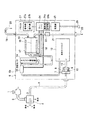
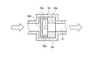
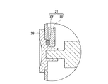
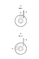
図1は、本実施形態にかかる水処理装置としてのアルカリイオン整水器の全体構成を説明する構成図である。図2は、流量切替弁を示す拡大断面図、図3は、流路切替弁の位置を検知する検知手段を模式的に示す断面図、図4は、検知手段をレバーの裏側から見た図であって、(a)は、アルカリ水モードが選択された状態を示す図、(b)は、浄水モードが選択された状態を示す図である。 FIG. 1 is a configuration diagram illustrating an overall configuration of an alkaline ionized water device as a water treatment apparatus according to the present embodiment. 2 is an enlarged cross-sectional view showing the flow rate switching valve, FIG. 3 is a cross-sectional view schematically showing detection means for detecting the position of the flow path switching valve, and FIG. 4 is a view of the detection means seen from the back side of the lever. (A) is a diagram showing a state in which the alkaline water mode is selected, and (b) is a diagram showing a state in which the water purification mode is selected.
本実施形態にかかるアルカリイオン整水器(水処理装置)6は、原水からアルカリイオン水や酸性イオン水を生成したり、原水を浄水したりする電解水生成装置として利用されるものであって、水道水等の原水を処理するアルカリイオン整水器6を台所や厨房等の流し台に設けられた水栓1に付設することで、アルカリイオン整水器6で処理された処理水を吐水口20から吐水できるようになっている。なお、このアルカリイオン整水器6は、流し台上に設置してもよいし、流し台の内部に設置する、いわゆるビルトインタイプとしてもよい。
The alkali ion water conditioner (water treatment device) 6 according to the present embodiment is used as an electrolyzed water generating device that generates alkaline ion water or acidic ion water from raw water or purifies raw water. By attaching an alkali
アルカリイオン整水器6は、図1に示すように、水道水等の原水を供給する水栓1に、給水管(水路)5を介して接続されている。水栓1には、原水管2を介して、水切替ユニット3が取り付けられており、この水切替ユニット3に設けられている水切替レバー4を図1に示すように上下方向に回動させることで、原水をそのまま使用する「原水」側の位置と、原水をアルカリイオン整水器6へ供給して浄水として使用する「浄水」側の位置とを切り替えている。
As shown in FIG. 1, the alkali
本実施形態では、水切替レバー4を上方に回動させると、水切替レバー4が「浄水」側の位置となり、原水がアルカリイオン整水器6へ供給されるようになる。
In the present embodiment, when the water switching lever 4 is rotated upward, the water switching lever 4 is positioned on the “purified water” side, and raw water is supplied to the alkali
具体的には、水切替レバー4が「浄水」側の位置のとき、原水は、本体部(装置本体)6a内の浄水カートリッジ12に接続されている給水管5を介してアルカリイオン整水器6の本体部6aへ供給され、浄水カートリッジ12内に供給されて浄水が行われる。
Specifically, when the water switching lever 4 is on the “purified” side, the raw water is supplied with an alkali ion water conditioner via a
ここで、本実施形態では、給水管5は、本体部6a内の浄水カートリッジ12の上流側で2つの水路に分岐した浄水水路8と電解水水路9とを備えており、当該2つの水路を選択的に塞ぐ水路切替弁を有する水質切替レバー7を操作することにより、浄水水路8と電解水水路9のうちの一方の側の水路が塞がれるとともに、他方の水路が連通されるようにしている。本実施形態では、本体部6aへ供給された水は、アルカリイオン整水器6を浄水モードで使用する場合には、浄水水路8を通過して浄水カートリッジ12内に供給され、電解水モードで使用する場合には、電解水水路9を通過して浄水カートリッジ12内に供給されるようになっている。
Here, in this embodiment, the
すなわち、水質切替レバー7は、アルカリイオン整水器から取り出す水を浄水またはアルカリイオン水のどちらにするかを選択するためのレバーである。
That is, the water
さらに、電解水水路9には、定流量弁10が設けられている。本実施形態では、定流量弁10は、樹脂等の硬質な材料で形成された有底円筒状のカップ部10aと、ゴム等の弾性材料で形成され、中心部に連通路が設けられた略円筒状の弁10bとを備えており、電解水水路9を拡径させた拡径部9aにカップ部10aを下流側に開口するように配置するとともに、弁10bを拡径部9aのカップ部10aの開口側(下流側)に配置している。
Further, a
そして、カップ部10aに、スリット10cを設け、水圧の変化によって電解水水路9の開口面積を変化させるようにすることで、浄水カートリッジ12に流入する水の流量が一定となるようにしている。
And the
具体的には、定流量弁10に流入する原水の流量が上昇し、カップ部10aの受圧面10dにかかる水圧が高まると、弁10bに当接しているカップ部10aのスリット10cが弁10bに押し付けられ、電解水水路9の開口面積が小さくなるようにしている。このように、受圧面10dにかかる水圧が高まった場合に、電解水水路9の開口面積を小さくすることで、電解水水路9を通過して浄水カートリッジ12に流入する原水の流量が一定となるように調節している。
Specifically, when the flow rate of the raw water flowing into the
このような定流量弁10を電解水水路9にのみ設けることで、水質切替レバー7を操作して浄水モードを選択した場合には、原水がそのまま浄水カートリッジ12に流入されるようにし、電解水モードを選択した場合には、原水が流量調節手段としての定流量弁10を介して浄水カートリッジ12に流入させ、後述する電解槽15に流入する水の流量を、当該電解槽15によるアリカリイオン水等の電解水の生成能力に応じた流量となるように制限している。
By providing such a
なお、カップ部10aに、水圧の変化によっても開口面積が変化しないスリットを設け、水栓1から所定流量の原水を供給した際に、電解水水路9を通過して浄水カートリッジ12に供給される流量の方が、浄水水路8を通過して浄水カートリッジ12に供給される流量よりも少なくなるようにするだけでもよい。
In addition, when the slit which does not change an opening area according to the change of water pressure is provided in the
さらに、本実施形態では、電解槽15よりも上流側かつ浄水カートリッジ12よりも上流側で浄水水路8および電解水水路9の2つの水路を合流させ、本体部6a内に供給された水が、浄水モード、電解水モードいずれの場合においても、合流水路11を介して浄水カートリッジ12に供給されるようにすることで、1つの浄水カートリッジ12を用いることができるようにしている。
Further, in the present embodiment, the two water channels of the purified
この浄水カートリッジ12は、原水中の残留塩素やトリハロメタン、カビ臭などを吸着する活性炭及び一般細菌や固形不純物を除去する中空糸膜などを備え、原水を浄化して浄水を生成する浄水部である。
This
そして、浄水カートリッジ12の下流には、流量センサ13が設けられており、この流量センサ13により浄水の流量が計測される。また、流量センサ13の下流には、グリセロリン酸カルシウムや乳酸カルシウムからカルシウムイオンを浄水に添加して導電率を高めるカルシウム供給部14が設けられている。流量センサ13で流量が計測された浄水の一部は、カルシウム供給部14を通過した後に、残部はそのままで、電解槽15へ流入する。
A
電解槽15は、電解槽15を二分して2つの電極室を形成する隔膜16と、各電極室に配置された電極板17,18を備えている。電解槽15は、通常運転時には、後述するコントローラ24から電極板17に負の直流電圧が供給され、電極板18に正の直流電圧が供給され、水の電気分解を行う電解部である。この結果、陰極側の電極室内にアルカリイオン水、陽極側の電極室内に酸性イオン水が生成されることになる。
The
電解槽15には、電極板17側の水(電極板17が陰極の場合、アルカリイオン水)を吐水口20から吐出する吐出管19と、電極板18側の水(電極板18が陽極の場合、酸性イオン水)と電解槽15内の滞留水や電極板洗浄時のカルシウム、マグネシウムなどからなるスケールが溶出した洗浄水を排水口23から排出するための排水管21が接続されている。そして、排水管21には、水質切替レバー7の操作と連動して開閉する切替弁22が設けられている。本実施形態では、切替弁22は、水質切替レバー7を操作して浄水モードを選択したときに閉じて、電解水モードを選択したときに開くように水質切替レバー7に連動させている。
The
コントローラ24は、アルカリオン整水器全体を制御すると共に、電極板17,18へ印加する直流の極性及び電圧電流を制御して、電解槽15による電気分解を制御する。またコントローラ24は、流量センサ13が検出した流量信号に基づいて、通水の有無、及び通水時の流量を検知する。
The
さらにコントローラ24は、演算部24aと、記憶部24bとを備えている。演算部24aは、アルカリイオン整水器6の動作状態である流量センサ13が検出した流量値、及び電極板17,18へ供給する電流値の積算値である積算電流値に基づいて、浄水カートリッジ12の寿命情報、及び電解槽15の寿命情報を演算する。記憶部24bは、演算部24aが演算した寿命情報を記憶する。記憶部24bは、EEPROMやフラッシュメモリ等を用いた記憶部であり、電源部25からの電源供給が停止しても記憶内容が消えない不揮発性の記憶部である。
Further, the
本実施形態において、記憶部24bが記憶する具体的な寿命情報としては、浄水カートリッジ12の寿命情報と、電解槽15の寿命情報とがある。さらにアルカリイオン整水器6に寿命管理が必要な部品があれば、その部品の寿命情報も記憶部24bに記憶することが可能である。
In the present embodiment, specific life information stored by the
浄水カートリッジ12の寿命情報としては、浄水カートリッジ12に通水した積算流量値や浄水カートリッジ12の交換後又は使用開始からの経過時間等が考えられる。したがって、表示部27aにカートリッジ交換ランプを設け、積算流量値が所定の通水限度流量値(例えば、12000リットル)、または、経過時間が所定の限界値(例えば、1年)に達したときに、当該カートリッジ交換ランプを点灯させることで、浄水カートリッジ12の寿命が尽きたことをを知らせるようにすることが可能である。また、電解槽15の寿命情報としては、電解槽15の通電時間の積算値である積算通電時間値を用いることが考えられるため、電解槽15の積算通電時間が850時間に達した際に、コントローラ24に電解槽15の寿命が尽きたと判断させて表示部27aの図示せぬ水質表示ランプを点灯させ、使用者に販売店または工事店に連絡するように促す表示を行うようにすることができる。
The life information of the
電源部25は、電源プラグ26から供給される商用交流電源のAC100Vから、コントローラ24が動作するための直流電圧、及びコントローラ24から電極板17,18へ供給するための直流電圧に変換して、コントローラ24へ供給する。
The
パネル部27は、表示部27aと、操作部27bとを備えている。表示部27aは、コントローラ24に接続され、アルカリイオン整水器6の動作状態、及び記憶部24bに記憶された寿命情報を表示することが可能である。操作部27bは、コントローラ24に接続され、アルカリイオン整水器6に対する動作設定が入力可能である。また、操作部27bは、コントローラ24の交換時に、記憶部24bに記憶された寿命情報を読み出す操作指示、或いは、使用開始日に関連する日付情報、或いは保守作業日の日付情報を入力することが可能である。
The panel unit 27 includes a
このパネル部27の表示部27aには、例えば、アルカリイオン整水器6が生成する水質を表示するために、浄水ランプと、弱酸性ランプと、弱アルカリランプと、強アルカリランプが設けられている。さらに、パネル部27の表示部には、アルカリイオン整水器6の状態として、弱酸性水またはアルカリイオン水を生成中であることを示す生成中ランプや、電解槽15の洗浄中であることを示す洗浄中ランプや、電解槽15の洗浄が必要なことを示す洗浄お知らせランプや、浄水カートリッジ12の交換が必要なことを示すカートリッジ交換ランプが設けられている。各ランプは、特に限定されないが、電力消費が小さく長寿命である発光ダイオードで構成するのが好適である。
In the
またパネル部27の操作部27bには、アルカリイオン整水器6に対する動作設定を入力するスイッチが設けられている。例えば、アルカリイオン整水器6で生成する水質を指示するために、弱酸性イオン水の生成を指示する弱酸性ボタンと、弱アルカリイオン水または強アルカリイオン水の生成を指示するアルカリボタンとを備えるようにすることが可能である。
The
さらにパネル部27の操作部27bに、浄水カートリッジ12の交換後にカートリッジ交換ランプを消灯させるとともに、コントローラ24に対して、カートリッジ交換を認識させ、浄水カートリッジ12の寿命情報をリセットさせるリセットボタンを設けてもよい。各ボタンは、特に限定されないが、防水性に優れたメンブレンスイッチで構成するのが好適である。
Further, a reset button is provided on the
また、本体部6aの外郭には、水路切替弁の位置を検知する検知手段31が設けられている。
Moreover, the detection means 31 which detects the position of a waterway switching valve is provided in the outline of the main-
本実施形態では、例えば、マグネット29が固定されたレバー28を水質切替レバー7に取り付け、レバー28を回動させることで、水質切替レバー7の水路切替弁を回動させて浄水水路8と電解水水路9の一方の水路を選択的に塞ぐようにしている。
In the present embodiment, for example, the
そして、図4(a)に示すように、浄水水路8が水路切替弁によって塞がれている時に、マグネット29が近づくとともに、図4(b)に示すように、電解水水路9が水路切替弁によって塞がれている時に、マグネット29が遠ざかる位置に、マグネット29が発生する磁力を検出する磁気センサ基板30を設けている。この磁気センサ基板30は、コントローラ24に接続されており、コントローラ24は、磁気センサ基板30が検出した磁気信号に基づいて、浄水モード、電解水モードのいずれが選択されたかを検知する。このように、マグネット29と磁気センサ基板30とが水路切替弁の位置を検知する検知手段31として機能している。
Then, as shown in FIG. 4 (a), when the purified
次に、本実施形態における浄水動作及び電解動作について説明する。 Next, the water purification operation and the electrolysis operation in this embodiment will be described.
まず使用者は、パネル部27の弱酸性ボタンとアルカリボタンとを使用して所望の水質を生成するモードを選択し、レバー28を回動させて本体部6aの水質切替レバー7を所望の水質に応じて浄水側又はアルカリ側に切り替え、水切替レバー4を浄水側へ切り替えて、水栓1を開く。
First, the user selects a mode for generating a desired water quality using the weakly acidic button and the alkali button on the panel unit 27, and rotates the
これにより、水栓1から供給された原水は、原水管2、水切替ユニット3、給水管5を経て、本体部6aに供給される。このとき、水質切替レバー7がアルカリ側である場合には定流量弁10を通過して一定の流量に制限された原水が浄水カートリッジ12へ供給され、水質切替レバー7が浄水側である場合には定流量弁10をバイパスして流量制限されない原水が浄水カートリッジ12へ供給される。浄水カートリッジ12で浄化された浄水は、流量センサ13で流量が検出され、カルシウム供給部14でカルシウム分が添加された浄水は、電解槽15へ流入する。
Thereby, the raw water supplied from the faucet 1 is supplied to the
コントローラ24は、流量センサ13が検出した流量値が所定値を超えると通水開始を認識して、流量センサ13が一定の通過水量毎に発生するパルス信号のカウントを開始することにより積算流量値の演算を開始する。またコントローラ24は、通水開始を認識すると、パネル部27および選択されるとともに検知手段31で検知したモード(或いは水質)に応じて、電解槽15への電圧印加を開始するとともに、通電開始から通電停止までの今回の通電時間の計測を始める。但し、浄水モードであれば、コントローラ24は電解槽15の電極板17、18には電圧を印加せず、通電時間の計測もしない。そして、浄水モードでは、水質切替レバー7の浄水側への切替に応じて切替弁22は閉じられて排水管21による排水は停止し、電気分解されない浄水が電解槽15から吐出管19を介して吐出され、利用可能となる。
When the flow rate value detected by the
パネル部27で選択されたモードが、強アリカリモードまたは弱アルカリモードであれば、コントローラ24は、電極板17に負電圧、電極板18に正電圧を印加して電解槽15に電気分解を行わせる。強アリカリモードでは、弱アルカリモードよりも電極板17,18に通電する電流値が大きく、水の単位流量当たりの通電電荷量が大きくなり、この結果、生成されるアルカリイオン水のpH値が相対的に高くなる。この電気分解により生成された強アルカリイオン水または弱アルカリイオン水は、陰極となった電極板17を備えた電極室から吐出管19を介して吐出され、利用可能となる。このとき同時に、陽極となった電極板18を備えた電極室からは、酸性水が切替弁22及び排水管21を介して排出される。
If the mode selected by the panel unit 27 is the strong antagonism mode or the weak alkali mode, the
逆にパネル部27で選択されたモードが弱酸性モードであれば、コントローラ24は、電極板17に正電圧、電極板18に負電圧を印加して電解槽15に電気分解を行わせる。この電気分解により生成された弱酸性イオン水は、陽極となった電極板17を備えた電極室から吐出管19を介して吐出され、利用可能となる。このとき同時に、陰極となった電極板18を備えた電極室からは、アルカリイオン水が切替弁22及び排水管21を介して排出される。
Conversely, if the mode selected by the panel unit 27 is a weak acid mode, the
所望の水質の水の利用が終わると、使用者は水栓1を閉じて、原水の供給を止める。原水の供給が止まると、流量センサ13が検出する流量値が所定値未満となり、コントローラ24は、止水を認識する。コントローラ24は、止水を認識すると、電解槽15への通電を停止する。またコントローラ24の演算部24aは、記憶部24bに記憶した積算流量値を読み出して、読み出した値に、今回の通水開始から通水停止までの積算流量値を加算して、記憶部24bへ上書きすることにより、記憶部24bに記憶した積算流量値を更新する。
When the use of the desired water quality is finished, the user closes the faucet 1 and stops the supply of raw water. When the supply of raw water stops, the flow rate value detected by the
またコントローラ24の演算部24aは、記憶部24bに記憶した電解槽15の積算通電時間値を読み出して、読み出した値に今回の電解槽15への通電時間値を加算して、記憶部24bへ上書きすることにより、記憶部24bに記憶した電解槽15の積算通電時間値を更新する。
In addition, the
コントローラ24は、電解動作または浄水動作の終了後、記憶部24bの更新後の積算流量値と予め設定された浄水カートリッジ12の通水限度流量値とを比較し、積算流量値が通水限度流量値を超えていれば、カートリッジ交換ランプ(図示せず)を点灯させる。さらに、コントローラ24は、電解動作または浄水動作の終了後、記憶部24bに記憶された浄水カートリッジ12の使用開始日或いは前回交換日と、現在の日付とを比較し、1年以上経過していれば、表示部27aに設けたカートリッジ交換ランプを点灯させる。
After the electrolysis operation or the water purification operation is completed, the
以上、説明したように、本実施形態では、給水管(水路)5に、浄水水路8と電解水水路9のいずれかを選択する水質切替レバー(水路切替手段)7を設けるとともに、電解水水路9に、当該電解水水路9内を流れる水の流量を調節する定流量弁(流量調節手段)10を設けた。よって、電解水モード選択時に、電解槽15に流入する水の流量を、当該電解槽15によるアリカリイオン水等の電解水の生成能力に応じた流量となるように制限することができるため、電解槽15の小型化を図ることが可能となり、アルカリイオン整水器(水処理装置)6の小型化を図ることが可能となる。さらに、電解水モード選択時にのみ電解槽15に流入する水の流量を制限させているため、浄水モードを選択した際に浄水の吐出流量が制限されることがなくなり、アルカリイオン整水器(水処理装置)6の使い勝手を良好にすることができる。
As described above, in the present embodiment, the water supply pipe (water channel) 5 is provided with the water quality switching lever (water channel switching means) 7 for selecting either the purified
このように、本実施形態によれば、浄水流量の低下を抑制しつつ小型化を図ることのできるアルカリイオン整水器(水処理装置)6を得ることができる。 Thus, according to this embodiment, it is possible to obtain an alkali ion water conditioner (water treatment device) 6 that can be downsized while suppressing a decrease in the purified water flow rate.
また、本体部6a内の電解槽15よりも上流側かつ浄水カートリッジ12よりも上流側で浄水水路8と電解水水路9とを合流させているため、部品点数の増加を抑えるとともに構成の簡素化を図ることができ、アルカリイオン整水器(水処理装置)6の製造コストを削減することができる。
Moreover, since the purified
また、本体部6aの外郭に水質切替レバー(水路切替手段)7の水路切替弁の位置を検知する検知手段31を設けたため、アルカリイオン整水器(水処理装置)6の浄水モードと電解水モードいずれかの選択を自動で制御することが可能となる。
Moreover, since the detection means 31 which detects the position of the water path switching valve of the water quality switching lever (water path switching means) 7 is provided in the outer part of the
以上、本発明の好適な実施形態について説明したが、本発明は上記実施形態には限定されず、種々の変形が可能である。 The preferred embodiments of the present invention have been described above. However, the present invention is not limited to the above embodiments, and various modifications can be made.
例えば、上記実施形態では、浄水モードの際にも水が電解槽を通過する構成としたが、電解槽を迂回する水路を設け、浄水モードの際には水が電解槽を通過しない構成とすることも可能である。 For example, in the above embodiment, water is configured to pass through the electrolytic cell even in the water purification mode. However, a water channel that bypasses the electrolytic cell is provided, and water is not configured to pass through the electrolytic cell in the water purification mode. It is also possible.
5 給水管(水路)
6 アルカリイオン整水器(水処理装置)
6a 本体部(装置本体)
7 水質切替レバー(水路切替手段)
8 浄水水路
9 電解水水路
10 定流量弁(流量調節手段)
12 浄水カートリッジ
15 電解槽
24 コントローラ(制御部)
31 検知手段
5 water supply pipe (waterway)
6 Alkaline ion water conditioner (water treatment device)
6a Body (device body)
7 Water quality switching lever (water channel switching means)
8 Clean water channel 9
12
31 Detection means
Claims (2)
前記水路に、前記浄水水路と電解水水路のいずれかを選択する水路切替手段を設けるとともに、前記電解水水路に、当該電解水水路内を流れる水の流量を調節する流量調節手段を設け、
前記水路切替手段を前記装置本体内に設け、
前記浄水カートリッジを前記電解槽の上流側に配置し、
前記浄水水路と電解水水路とを前記装置本体内の前記浄水カートリッジよりも上流側で合流させたことを特徴とする水処理装置。 An apparatus main body having a water purification cartridge for purifying raw water and an electrolytic tank for electrolyzing the raw water or purified water, a purified water channel through which water flows when discharging purified water, and an electrolytic water channel through which water flows when discharging electrolytic water A water treatment device comprising:
The water channel is provided with water channel switching means for selecting either the purified water channel or the electrolyzed water channel, and the electrolyzed water channel is provided with flow rate adjusting means for adjusting the flow rate of water flowing in the electrolyzed water channel ,
The water channel switching means is provided in the apparatus body,
The water purification cartridge is disposed on the upstream side of the electrolytic cell,
A water treatment apparatus, wherein the purified water channel and the electrolyzed water channel are merged upstream of the purified water cartridge in the apparatus main body .
Priority Applications (5)
| Application Number | Priority Date | Filing Date | Title |
|---|---|---|---|
| JP2008310952A JP4697293B2 (en) | 2008-12-05 | 2008-12-05 | Water treatment equipment |
| TW098141016A TWI388369B (en) | 2008-12-05 | 2009-12-01 | Water treatment unit |
| KR1020090118029A KR101151498B1 (en) | 2008-12-05 | 2009-12-01 | Water treatment apparatus |
| CN2009102531466A CN101746853B (en) | 2008-12-05 | 2009-12-04 | Water treatment apparatus |
| HK10111759.6A HK1145314B (en) | 2008-12-05 | 2010-12-16 | Water treatment apparatus |
Applications Claiming Priority (1)
| Application Number | Priority Date | Filing Date | Title |
|---|---|---|---|
| JP2008310952A JP4697293B2 (en) | 2008-12-05 | 2008-12-05 | Water treatment equipment |
Publications (2)
| Publication Number | Publication Date |
|---|---|
| JP2010131545A JP2010131545A (en) | 2010-06-17 |
| JP4697293B2 true JP4697293B2 (en) | 2011-06-08 |
Family
ID=42343423
Family Applications (1)
| Application Number | Title | Priority Date | Filing Date |
|---|---|---|---|
| JP2008310952A Expired - Fee Related JP4697293B2 (en) | 2008-12-05 | 2008-12-05 | Water treatment equipment |
Country Status (4)
| Country | Link |
|---|---|
| JP (1) | JP4697293B2 (en) |
| KR (1) | KR101151498B1 (en) |
| CN (1) | CN101746853B (en) |
| TW (1) | TWI388369B (en) |
Families Citing this family (6)
| Publication number | Priority date | Publication date | Assignee | Title |
|---|---|---|---|---|
| JP5417301B2 (en) * | 2010-11-10 | 2014-02-12 | パナソニック株式会社 | Water treatment equipment |
| JP2014046233A (en) * | 2012-08-30 | 2014-03-17 | Panasonic Corp | Electrolytic water producing device |
| JP2014046232A (en) * | 2012-08-30 | 2014-03-17 | Panasonic Corp | Electrolytic water producing device |
| CN108706688A (en) * | 2018-05-28 | 2018-10-26 | 佛山市顺德区悍高五金制品有限公司 | A kind of electrolysis unit applied to sink |
| CN109809529B (en) * | 2018-09-10 | 2022-03-29 | 悍高集团股份有限公司 | Electrolysis device capable of being automatically cleaned and automatic cleaning method thereof |
| KR102585707B1 (en) * | 2022-02-18 | 2023-10-06 | 대림통상 주식회사 | Bath cleaning apparatus with electrolyzed water supply function |
Family Cites Families (7)
| Publication number | Priority date | Publication date | Assignee | Title |
|---|---|---|---|---|
| JPH0691267A (en) * | 1992-09-10 | 1994-04-05 | Jiyanitsukusu Kk | Control apparatus for continuous electrolytic water generator |
| JPH0716570A (en) * | 1993-06-30 | 1995-01-20 | Sanyo Electric Co Ltd | Ionic water preparation instrument |
| JPH08243563A (en) * | 1995-03-15 | 1996-09-24 | Tec Corp | Electrolytic ionic water generator |
| JP2002361251A (en) * | 2001-06-07 | 2002-12-17 | Toto Ltd | Electrolytic water generator |
| KR200330824Y1 (en) | 2003-07-30 | 2003-10-22 | 이수테크 주식회사 | Apparatus for manufacturing ionic water |
| CN100465831C (en) * | 2007-03-21 | 2009-03-04 | 王广生 | Intelligent water trcatment device |
| KR20090043787A (en) * | 2007-10-30 | 2009-05-07 | 웅진코웨이주식회사 | Water Ionizer with Water Purification |
-
2008
- 2008-12-05 JP JP2008310952A patent/JP4697293B2/en not_active Expired - Fee Related
-
2009
- 2009-12-01 TW TW098141016A patent/TWI388369B/en not_active IP Right Cessation
- 2009-12-01 KR KR1020090118029A patent/KR101151498B1/en not_active Expired - Fee Related
- 2009-12-04 CN CN2009102531466A patent/CN101746853B/en not_active Expired - Fee Related
Also Published As
| Publication number | Publication date |
|---|---|
| CN101746853A (en) | 2010-06-23 |
| TW201028202A (en) | 2010-08-01 |
| KR101151498B1 (en) | 2012-05-30 |
| HK1145314A1 (en) | 2011-04-15 |
| CN101746853B (en) | 2012-10-03 |
| JP2010131545A (en) | 2010-06-17 |
| KR20100065105A (en) | 2010-06-15 |
| TWI388369B (en) | 2013-03-11 |
Similar Documents
| Publication | Publication Date | Title |
|---|---|---|
| JP4697293B2 (en) | Water treatment equipment | |
| TWI721195B (en) | Electrolyzed water generating device | |
| JP2006187714A (en) | Ionized water generator | |
| JP2000317451A (en) | Alkaline ion water purifier | |
| JPH01203097A (en) | Apparatus for producing electrolytic ionic water | |
| JP4556569B2 (en) | Generator and water discharge control device | |
| JP2000202449A (en) | Alkaline ion water purifier | |
| HK1145314B (en) | Water treatment apparatus | |
| JP3882509B2 (en) | Electrolyzed water generator | |
| JPH08173964A (en) | Electrolytic water-producing apparatus | |
| JP3484762B2 (en) | Electrolyzed water generator | |
| JP3991994B2 (en) | Electrolyzed water generator | |
| JP3991995B2 (en) | Electrolyzed water generator | |
| JP4474889B2 (en) | Ion water conditioner | |
| JP2007000740A (en) | Sterilization washing device | |
| JP3906518B2 (en) | Built-in alkaline water conditioner | |
| JP3835177B2 (en) | Electrolyzed water generator | |
| JP4936423B2 (en) | Electrolyzed water generating device and sink equipped with the same | |
| JP2010051880A (en) | Water treatment device | |
| JPH1043760A (en) | Alkaline ion water purifier | |
| JP2006167503A (en) | Alkaline ion water conditioner | |
| JP3760676B2 (en) | Alkaline ion water conditioner | |
| JP2006075700A (en) | Alkaline ion water conditioner | |
| KR20050081015A (en) | Water ionizer | |
| JP2006167504A (en) | Alkaline ion water conditioner |
Legal Events
| Date | Code | Title | Description |
|---|---|---|---|
| A621 | Written request for application examination |
Free format text: JAPANESE INTERMEDIATE CODE: A621 Effective date: 20100709 |
|
| A977 | Report on retrieval |
Free format text: JAPANESE INTERMEDIATE CODE: A971007 Effective date: 20101129 |
|
| A131 | Notification of reasons for refusal |
Free format text: JAPANESE INTERMEDIATE CODE: A131 Effective date: 20101207 |
|
| A521 | Request for written amendment filed |
Free format text: JAPANESE INTERMEDIATE CODE: A523 Effective date: 20110112 |
|
| A01 | Written decision to grant a patent or to grant a registration (utility model) |
Free format text: JAPANESE INTERMEDIATE CODE: A01 Effective date: 20110201 |
|
| A61 | First payment of annual fees (during grant procedure) |
Free format text: JAPANESE INTERMEDIATE CODE: A61 Effective date: 20110214 |
|
| LAPS | Cancellation because of no payment of annual fees |