JP4697151B2 - Massage machine - Google Patents

Massage machine Download PDF

Info

Publication number
JP4697151B2
JP4697151B2 JP2007016100A JP2007016100A JP4697151B2 JP 4697151 B2 JP4697151 B2 JP 4697151B2 JP 2007016100 A JP2007016100 A JP 2007016100A JP 2007016100 A JP2007016100 A JP 2007016100A JP 4697151 B2 JP4697151 B2 JP 4697151B2
Authority
JP
Japan
Prior art keywords
procedure
treatment element
unit
massage
user
Prior art date
Legal status (The legal status is an assumption and is not a legal conclusion. Google has not performed a legal analysis and makes no representation as to the accuracy of the status listed.)
Expired - Fee Related
Application number
JP2007016100A
Other languages
Japanese (ja)
Other versions
JP2008178633A (en
Inventor
孝欣 谷澤
聡 梶山
裕一 西堀
文宏 西尾
大輔 塚田
佳子 辻
Current Assignee (The listed assignees may be inaccurate. Google has not performed a legal analysis and makes no representation or warranty as to the accuracy of the list.)
Panasonic Corp
Panasonic Electric Works Co Ltd
Original Assignee
Panasonic Corp
Matsushita Electric Works Ltd
Priority date (The priority date is an assumption and is not a legal conclusion. Google has not performed a legal analysis and makes no representation as to the accuracy of the date listed.)
Filing date
Publication date
Application filed by Panasonic Corp, Matsushita Electric Works Ltd filed Critical Panasonic Corp
Priority to JP2007016100A priority Critical patent/JP4697151B2/en
Publication of JP2008178633A publication Critical patent/JP2008178633A/en
Application granted granted Critical
Publication of JP4697151B2 publication Critical patent/JP4697151B2/en
Expired - Fee Related legal-status Critical Current
Anticipated expiration legal-status Critical

Links

Images

Description

本発明は、マッサージ機に関するものである。   The present invention relates to a massage machine.

近年、マッサージ機は、多機能化傾向にあり、機能の中でも人間がマッサージを行っているような感覚を使用者に与えることが求められている。それを実現するために、手技数を増やすことで、人間がマッサージされているような感覚を使用者に与える試みがなされている。実際、900を超える手技数を有するマッサージ機も知られており、使用者はこれら多数の手技から好みの手技を選択し、マッサージ機にマッサージを実行させる。   In recent years, massage machines have a tendency to become multifunctional, and it is required to give a user a sense that a person is performing massage among functions. In order to achieve this, an attempt has been made to give the user a sense that a human is being massaged by increasing the number of procedures. In fact, massage machines having a number of procedures exceeding 900 are also known, and the user selects a favorite technique from these many techniques and causes the massage machine to perform massage.

また、特許文献1には、使用者が望むツボの位置にマッサージを行うことを目的として、マッサージを施す位置としてツボを選択するツボ入力部と、選択されたツボに対応する身体の箇所へマッサージを施すための位置制御を行う制御部とを備えるマッサージ機が開示されている。
特開2001−161767号公報
Patent Document 1 discloses a massage input to select acupuncture points as massage positions for the purpose of performing massage at the position of the pressure points desired by the user, and massage to a body location corresponding to the selected pressure points. A massage machine is disclosed that includes a control unit that performs position control for applying the massage.
JP 2001-161767 A

しかしながら、手技数を増加させ揉みほぐす筋肉やツボが増加すると、マッサージの知識の豊富な使用者にとっては自由度が増えるが、マッサージの知識の乏しい使用者は充分にマッサージ効果を得ることができないという問題があった。すなわち、手技に応じて好ましいマッサージ位置が存在するが、選択した手技において、好ましいマッサージ位置を知らない使用者は、好ましいマッサージ位置に施療子を移動させることができず充分なマッサージ効果を得ることができないという問題があった。   However, increasing the number of procedures and the number of muscles and acupoints to massage will increase the degree of freedom for massage-rich users, but users with poor massage knowledge will not be able to obtain a sufficient massage effect. was there. That is, there is a preferred massage position depending on the procedure, but a user who does not know the preferred massage position in the selected procedure cannot move the treatment element to the preferred massage position and can obtain a sufficient massage effect. There was a problem that I could not.

本発明の目的は、マッサージ効果の高い位置を使用者に認識させることができるマッサージ機を提供することである。   The objective of this invention is providing the massage machine which can make a user recognize the position with a high massage effect.

本発明によるマッサージ機は、背もたれ部に配設された施療子が、3次元的に移動することで所定の手技を前記背もたれ部の任意の位置で行うマッサージ機であって、使用者の操作指令に従って手技を設定する手技設定手段と、使用者の操作指令に従って、前記施療子の位置を調節すると共に、前記手技設定手段により設定された手技に対して予め定められた動作パターンに従って前記施療子を駆動する駆動手段と、前記手技設定手段により設定された手技に対して予め定められたマッサージ効果の高い位置を使用者に報知する報知手段とを備えることを特徴とする。   A massage machine according to the present invention is a massage machine that performs a predetermined procedure at an arbitrary position of the backrest portion by three-dimensionally moving a treatment element disposed on the backrest portion, and is provided with a user operation command. Adjusting the position of the treatment element according to a user's operation command and adjusting the position of the treatment element according to a predetermined operation pattern for the technique set by the technique setting means. It is characterized by comprising driving means for driving and notifying means for notifying the user of a position having a high massage effect predetermined for the procedure set by the procedure setting means.

この構成によれば、手技設定手段により設定された手技に対して予め定められたマッサージ効果の高い体型上の位置が使用者に報知されるため、マッサージ効果の高い位置を使用者に認識させることができる。そのため、使用者は、施療子の位置をマッサージ効果の高い位置に移動して、選択した手技によるマッサージを実行することで、高いマッサージ効果を得ることができる。   According to this configuration, since the position on the body shape having a high massage effect predetermined for the procedure set by the procedure setting means is notified to the user, the user is made to recognize the position having a high massage effect. Can do. Therefore, the user can obtain a high massage effect by moving the position of the treatment element to a position having a high massage effect and performing a massage by the selected procedure.

また、前記駆動手段により駆動されている施療子の現在位置を検出する位置検出手段を更に備え、前記報知手段は、マッサージ効果の高い位置に加えて、前記位置検出手段により検出された施療子の現在位置を報知することが好ましい。   Further, the apparatus further comprises position detecting means for detecting a current position of the treatment element driven by the driving means, and the notification means includes a position of the treatment element detected by the position detection means in addition to a position having a high massage effect. It is preferable to notify the current position.

この構成によれば、施療子の現在位置がリアルタイムに報知されるため、マッサージ効果の高い位置と実際に施療子が駆動している位置とのずれを認識することができる。   According to this configuration, since the current position of the treatment element is notified in real time, it is possible to recognize a deviation between a position having a high massage effect and a position where the treatment element is actually driven.

また、前記報知手段は、前記手技設定手段により設定された手技により動作する施療子の動作の特徴を良く表すことのできる方向から人間を見たときの体型画像上に、マッサージ効果の高い位置を示すと共に、施療子の現在位置とを示す画像を表示部に表示することが好ましい。   Further, the notifying means provides a position having a high massage effect on the body shape image when a person is seen from a direction that can well represent the characteristics of the operation of the treatment element operated by the procedure set by the procedure setting unit. It is preferable to display an image indicating the current position of the treatment element on the display unit.

この構成によれば、手技に応じて施療子の現在位置が見やすくなるような方向から人間をみたときの体型画像上に施療子の現在位置とマッサージ効果の高い位置とが表示されるため、施療子の現在位置の視認性を向上させることができる。   According to this configuration, the current position of the treatment element and the position having a high massage effect are displayed on the body image when the person is viewed from a direction that makes it easier to see the current position of the treatment element according to the procedure. The visibility of the current position of the child can be improved.

前記報知手段は、前記手技設定手段により設定された手技に関連するツボの位置と、前記手技による効能とを報知することが好ましい。   It is preferable that the notification means notifies the position of the acupoint related to the procedure set by the procedure setting unit and the effectiveness of the procedure.

この構成によれば、設定されている手技に関連するツボの位置と効能とが報知されるため、使用者は設定されている手技に対する知識を増すことができる。   According to this configuration, since the position and efficacy of the acupoint related to the set procedure are notified, the user can increase knowledge of the set procedure.

本発明によれば、マッサージ効果の高い位置を使用者に認識させることができる。そのため、使用者は、施療子の位置をマッサージ効果の高い位置に移動して、選択した手技によるマッサージを実行することで、高いマッサージ効果を得ることができる。   According to the present invention, a user can recognize a position having a high massage effect. Therefore, the user can obtain a high massage effect by moving the position of the treatment element to a position having a high massage effect and performing a massage by the selected procedure.

以下、本発明の実施の形態によるマッサージ機について説明する。なお、各図において同一の符号を付した構成は同一の構成を表すものとして説明を省略する。図1は、マッサージ機の外観構成図を示している。図1に示すように、マッサージ機は、各種のマッサージ動作を行うリクライニング可能な椅子1から構成され、背もたれ部2と、背もたれ部2の下側に配設された座部3と、座部3の左右両側に設けられた肘掛け部の一方側に配設された操作部4と、座部3の下側に配設された脚載せ台5とを備えている。なお、図1において、前後方向は、背もたれ部2において使用者の背中が当接する背もたれ面に直交する方向を示し、使用者に近づく方向を前方向とし、使用者から離れる前方向とは反対側の方向を後方向とする。上下方向は、背もたれ面の上端から下端に向かう下方向と下端から上端に向かう上方向とを総称した方向を示す。また、左右方向は、背もたれ面において上下方向と直交する方向を示し、背もたれ面の右端から左端に向かう方向を左方向とし、背もたれ面の左端から右端に向かう方向を右方向とする。   Hereinafter, a massage machine according to an embodiment of the present invention will be described. In addition, the structure which attached | subjected the same code | symbol in each figure represents the same structure, and abbreviate | omits description. FIG. 1 shows an external configuration diagram of a massage machine. As shown in FIG. 1, the massage machine includes a reclining chair 1 that performs various massage operations, a backrest 2, a seat 3 disposed below the backrest 2, and a seat 3. The operation part 4 arrange | positioned at the one side of the armrest part provided in the both right and left sides, and the leg stand 5 arrange | positioned under the seat part 3 are provided. In FIG. 1, the front-rear direction indicates a direction perpendicular to the backrest surface with which the user's back abuts in the backrest portion 2, the direction approaching the user is the front direction, and the opposite side from the front direction away from the user Is the rear direction. The vertical direction indicates a direction in which a downward direction from the upper end to the lower end of the backrest surface and an upward direction from the lower end to the upper end are collectively referred to. The left-right direction indicates a direction orthogonal to the up-down direction on the backrest surface, the direction from the right end to the left end of the backrest surface is the left direction, and the direction from the left end to the right end of the backrest surface is the right direction.

操作部4は、椅子1とケーブルCAを介して接続され、ユーザが各種操作指令を入力する際に用いられる。背もたれ部2は椅子1に腰掛けた使用者の背中が当接し、内部に一対の施療子(もみ玉)を含むマッサージ部21が配設されている。座部3は、椅子1に腰掛けたユーザの臀部と太ももとが載置される。脚載せ台5は、使用者のふくらはぎ及び足裏が載置される。   The operation unit 4 is connected to the chair 1 via the cable CA and is used when the user inputs various operation commands. The backrest 2 is in contact with the back of the user sitting on the chair 1, and a massage part 21 including a pair of treatment elements (rice balls) is disposed inside. The seat 3 is placed with the user's buttocks and thighs sitting on the chair 1. The user's calf and sole are placed on the leg platform 5.

図2は、操作部4の外観構成図を示している。操作部4は、電源をオン・オフする「切/入」ボタン41と、予めプログラムによって手技、施療位置、施療回数等が決められた全身自動コースを選択するための全自動コースボタン42と、使用者がその日の体調や気分によって、全身のどの部位をどの程度施療するかを選択することにより、手技、施療位置、施療回数等を自動的に計算し、マッサージ内容を作成する問診コースを選択するための「問診コース」ボタン43と、全身自動コース及び問診コースとは異なり、使用者が選んだ手技を、使用者が解除するまで、使用者の好みの位置で行うことができるお好み動作を選択するための「お好み動作」ボタン44と、問診コースでは人体の各部位のお疲れ度を入力際に使用され、お好み動作では使用者が選択する部位と手技とを選択するために使用される部位選択ボタン45と、施療子22を前後方向に移動させ、マッサージの強弱を調整するための強弱ボタン49と、施療子22の上下方向及び左右方向の位置を調整するための位置調整ボタン46と、施療子22の移動速度を調節する速度調節ボタン50と、施療内容、施療位置、施療の強さ等の種々の情報を表示するための表示部47と、施療を直ちに停止させるための「急停止」ボタン48等を備えている。   FIG. 2 is an external configuration diagram of the operation unit 4. The operation unit 4 includes an “OFF / ON” button 41 for turning on / off the power, a fully automatic course button 42 for selecting a whole body automatic course in which a procedure, a treatment position, a number of treatments, and the like are determined in advance by a program, Select the interview course to create massage contents by automatically calculating the procedure, treatment position, number of treatments, etc. by selecting how much of the whole body to treat according to the physical condition and mood of the day “Interview course” button 43 for the user, and unlike the whole body automatic course and the interview course, the user's favorite operation can be performed at the user's preferred position until the user releases the procedure selected by the user "Favorite action" button 44 for selecting the user, and in the inquiry course, it is used when inputting the fatigue level of each part of the human body. In the favorite action, the user selects a part and a technique to be selected. A region selection button 45 used for moving the treatment element 22 in the front-rear direction, a strength button 49 for adjusting the strength of the massage, and a position for adjusting the vertical and horizontal positions of the treatment element 22 Position adjustment button 46, speed adjustment button 50 for adjusting the moving speed of treatment element 22, display section 47 for displaying various information such as treatment content, treatment position, treatment intensity, and treatment are immediately stopped. A “sudden stop” button 48 or the like is provided.

図3は、マッサージ部21の外観構成図を示している。図3に示すようにマッサージ部21は、左右対称に配設された一対の施療子22を含む施療子部と、施療子を前後方向に移動させる強弱駆動部と、施療子22を左右方向に移動させる幅駆動部と、施療子22を上下方向に移動させる上下駆動部とを備えている。   FIG. 3 shows an external configuration diagram of the massage unit 21. As shown in FIG. 3, the massage unit 21 includes a treatment element unit including a pair of treatment elements 22 disposed symmetrically, a strength and weakness drive unit that moves the treatment element in the front-rear direction, and the treatment element 22 in the left-right direction. A width driving unit to be moved and a vertical driving unit to move the treatment element 22 in the vertical direction are provided.

施療子部は、左右一対の施療子22と、各施療子22を支持する一対の施療子アーム221とを備えている。強弱駆動部は、各施療子アーム221の外側に配設された一対の前後駆動用歯車211と、施療子22を前後方向に移動させる際の駆動源となる前後モータ212と、両端に一対の伝達用歯車214が配設され、前後モータ212からの動力を伝達用歯車214を介して前後駆動用歯車211に伝達するための前後駆動軸213と、施療子22の前後方向の位置を検出する強弱センサ215とを備えている。すなわち、前後モータ212が正回転、又は逆回転すると、その動力が図略の歯車を介して、前後駆動軸213へと伝達され、前後駆動軸213が回転し、前後駆動軸213の動力が伝達用歯車214を介して、前後駆動用歯車211へと伝達され、施療子アーム221が前後駆動用歯車211の中心を軸芯として回転し、施療子22が回転する。これにより、施療子22が使用者に近づいたり離れたりして前後方向に移動する。強弱センサ215は、前後駆動用歯車211の回転軸上に設けられたロータリーエンコーダから構成され、施療子22の回転角度から施療子22の前後方向における位置を検出する。   The treatment element unit includes a pair of left and right treatment elements 22 and a pair of treatment element arms 221 that support the treatment elements 22. The strength and weakness drive unit includes a pair of front and rear drive gears 211 disposed on the outside of each treatment element arm 221, a front and rear motor 212 serving as a drive source for moving the treatment element 22 in the front and rear direction, and a pair of both ends. A transmission gear 214 is provided to detect the front-rear drive shaft 213 for transmitting the power from the front-rear motor 212 to the front-rear drive gear 211 via the transmission gear 214 and the position of the treatment element 22 in the front-rear direction. And a strength sensor 215. That is, when the front / rear motor 212 rotates forward or backward, the power is transmitted to the front / rear drive shaft 213 via a gear (not shown), the front / rear drive shaft 213 rotates, and the power of the front / rear drive shaft 213 is transmitted. This is transmitted to the front / rear drive gear 211 via the gear 214, and the treatment element arm 221 rotates about the center of the front / rear drive gear 211 as an axis, and the treatment element 22 rotates. Thereby, the treatment element 22 moves to the front-back direction, approaching or leaving the user. The strength sensor 215 is composed of a rotary encoder provided on the rotation shaft of the front / rear drive gear 211, and detects the position of the treatment element 22 in the front-rear direction from the rotation angle of the treatment element 22.

幅駆動部は、駆動源となる左右モータ222と、左右モータ222からの動力を左右駆動軸223に伝達するためのプーリ227、ベルト225、及びプーリ226と、左右方向を長手方向とし、左右モータ222により回転される左右駆動軸223と、左右駆動軸223と噛み合い、施療子アーム221の各々を左右方向に移動させる一対の雄ネジ224と、施療子22の左右方向の位置を検出する幅センサ(図略)とを備えている。ここで、ベルト225は、プーリ227とプーリ226との間で架け渡された無端ベルトである。また、雄ネジ224は、左右駆動軸223の中心から左右対称となる位置に配設され、一方の雄ネジ224が他方の雄ネジ224に対して逆ネジの方向となるように、左右駆動軸223と噛み合っている。従って、左右モータ222が正方向、又は逆方向に回転すると、その動力がプーリ227、ベルト225、及びプーリ226を介し左右駆動軸223に伝達され、左右駆動軸223が回転し、一対の施療子アーム221が互いに近づいたり離れたりして左右対称に移動する。   The width drive unit includes a left and right motor 222 serving as a drive source, a pulley 227, a belt 225, and a pulley 226 for transmitting power from the left and right motor 222 to the left and right drive shafts 223. A left and right drive shaft 223 rotated by 222, a pair of male screws 224 that mesh with the left and right drive shaft 223 and move each of the treatment element arms 221 in the left and right direction, and a width sensor that detects the position of the treatment element 22 in the left and right direction (Not shown). Here, the belt 225 is an endless belt stretched between the pulley 227 and the pulley 226. Further, the male screw 224 is disposed at a position that is symmetrical with respect to the center of the left and right drive shaft 223, and the left and right drive shafts so that one male screw 224 is in the direction of the reverse screw with respect to the other male screw 224. 223 is engaged. Accordingly, when the left / right motor 222 rotates in the forward direction or the reverse direction, the power is transmitted to the left / right drive shaft 223 via the pulley 227, the belt 225, and the pulley 226, and the left / right drive shaft 223 rotates, and a pair of treatment elements The arms 221 move symmetrically as they approach or separate from each other.

上下駆動部は、駆動源としての上下モータ231と、上下モータ231からの動力を伝達し、左右方向を長手方向とする図略の駆動軸と、この駆動軸の両端に配設された一対のローラ232及びピニオン233と、上下方向を長手方向とし、マッサージ部21の上下方向の移動を案内するための一対のレール(図略)と、各レールに設けられたラック(図略)と、施療子22の上下方向の位置を検出するための上下センサ234とを備えている。ピニオン233はラックと噛み合い、ローラ232はレールに嵌め込まれている。そのため、上下モータ231が正方向、又は逆方向に回転すると、図略の回転軸が回転し、ピニオン233が回転し、ローラ232がレールに沿って移動し、マッサージ部21が上下方向に移動する。このように、施療子22は、上下方向、左右方向、及び前後方向に移動されて後3次元的に移動し、マッサージ動作を行う。   The vertical drive unit transmits a power from the vertical motor 231 as a drive source, power from the vertical motor 231, and a pair of drive shafts (not shown) whose longitudinal direction is the horizontal direction, and a pair of both ends of the drive shaft. The roller 232 and the pinion 233, a pair of rails (not shown) for guiding the movement of the massage unit 21 in the up-down direction with the vertical direction as the longitudinal direction, racks (not shown) provided on each rail, and treatment And a vertical sensor 234 for detecting the position of the child 22 in the vertical direction. The pinion 233 meshes with the rack, and the roller 232 is fitted in the rail. Therefore, when the vertical motor 231 rotates in the forward direction or the reverse direction, the rotation shaft (not shown) rotates, the pinion 233 rotates, the roller 232 moves along the rail, and the massage unit 21 moves up and down. . Thus, the treatment element 22 is moved in the up-down direction, the left-right direction, and the front-rear direction, and then moved three-dimensionally to perform a massage operation.

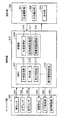
図4は、本マッサージ機の電気的な構成を示すブロック図である。マッサージ機は、マッサージ部300、制御部310、及び操作部320を備えている。マッサージ部300は、図3に示すマッサージ部21から構成され、幅センサ301、上下センサ302、強弱センサ303、幅駆動部304、上下駆動部305、及び強弱駆動部306を備えている。幅センサ301は、図3で説明した幅センサから構成され、施療子22の左右方向の位置を検出する。上下センサ302は、図3に示す上下センサ234から構成され、施療子22の上下方向の位置を検出する。強弱センサ303は図3に示す強弱センサ215から構成され、施療子22の前後方向の位置を検出する。   FIG. 4 is a block diagram showing an electrical configuration of the massage machine. The massage machine includes a massage unit 300, a control unit 310, and an operation unit 320. The massage unit 300 includes the massage unit 21 illustrated in FIG. 3, and includes a width sensor 301, a vertical sensor 302, a strength sensor 303, a width driving unit 304, a vertical driving unit 305, and a strength driving unit 306. The width sensor 301 includes the width sensor described with reference to FIG. 3 and detects the position of the treatment element 22 in the left-right direction. The vertical sensor 302 is composed of the vertical sensor 234 shown in FIG. 3 and detects the vertical position of the treatment element 22. The strength sensor 303 includes a strength sensor 215 shown in FIG. 3 and detects the position of the treatment element 22 in the front-rear direction.

幅駆動部304は、図3に示す幅駆動部から構成され、施療子22を左右方向に移動させる。上下駆動部305は、図3に示す上下駆動部から構成され、施療子22を上下方向に移動させる。強弱駆動部306は、図3に示す強弱駆動部から構成され、施療子22を前後方向に移動させる。   The width drive unit 304 includes the width drive unit shown in FIG. 3 and moves the treatment element 22 in the left-right direction. The vertical drive part 305 is comprised from the vertical drive part shown in FIG. 3, and moves the treatment element 22 to an up-down direction. The strength driving unit 306 includes the strength driving unit shown in FIG. 3 and moves the treatment element 22 in the front-rear direction.

制御部310は、MPU(microprocessor)311、動作駆動制御部312(駆動手段)、及び記憶部319を備えている。MPU311は、本マッサージ機の全体制御を司り、手技設定部313(手技設定手段)、特定部314、及び表示制御部315(報知手段)を備えている。   The control unit 310 includes an MPU (microprocessor) 311, an operation drive control unit 312 (drive means), and a storage unit 319. The MPU 311 governs overall control of the massage machine, and includes a procedure setting unit 313 (procedure setting unit), a specifying unit 314, and a display control unit 315 (notification unit).

手技設定部313は、使用者が操作部320を操作することで入力した操作指令に従って手技を設定する。   The procedure setting unit 313 sets a procedure according to an operation command input by the user operating the operation unit 320.

特定部314は、手技設定部313により設定された手技に応じてマッサージ効果の高い位置(目標マッサージ位置)を特定する。ここで、特定部314は、マッサージ対象となる使用者をセンシングして、使用者の体型情報を取得し、手技設定部313により設定された手技に対して標準体型上において予め定められた目標マッサージ位置を位置記憶部316から特定し、特定した目標マッサージ位置と、センシングにより取得した体型情報とから、マッサージ対象となる使用者の目標マッサージ位置を特定する。   The specifying unit 314 specifies a position having a high massage effect (target massage position) according to the procedure set by the procedure setting unit 313. Here, the specifying unit 314 senses the user to be massaged, acquires the user's body shape information, and the target massage predetermined on the standard body shape for the procedure set by the procedure setting unit 313 The position is specified from the position storage unit 316, and the target massage position of the user to be massaged is specified from the specified target massage position and the body shape information acquired by sensing.

なお、特定部314は、マッサージ部300を駆動して施療子22を上下方向の下端位置U1から上端位置U2まで上下方向に移動させ、幅センサ301、上下センサ302、及び強弱センサ303による施療子22の位置の検出結果を取得し、取得した検出結果から使用者の体型情報を取得する。体型情報としては、使用者の肩の位置を示す情報等が含まれる。また、標準体型は、例えば数千人から数万人の人間の体型情報の平均値をとることで算出されたものであり、標準的な人体の体型を示す。また、目標マッサージ位置は、ある手技を行うにあたり高いマッサージ効果を得ることができる体型上の位置を示し、手技毎に予め定められている。   The specifying unit 314 drives the massage unit 300 to move the treatment element 22 in the vertical direction from the lower end position U1 in the vertical direction to the upper end position U2, and the treatment element by the width sensor 301, the vertical sensor 302, and the strength sensor 303. The detection result of 22 positions is acquired, and a user's body type information is acquired from the acquired detection result. The body type information includes information indicating the position of the user's shoulder. The standard figure is calculated by taking the average value of the figure information of, for example, thousands to tens of thousands of people, and indicates the standard figure of the human body. The target massage position indicates a position on the body shape where a high massage effect can be obtained in performing a certain procedure, and is determined in advance for each procedure.

表示制御部315は、特定部314により特定された、マッサージ対象となる使用者の目標マッサージ位置を使用者に報知するための報知画像を表示部323に表示する。ここで、表示制御部315は、手技設定部313により設定された手技と関連づけられた体型画像を体型画像記憶部317から特定し、特定した体型画像上に目標マッサージ位置を示す目印を付した画像を報知画像として表示部323に表示する。   The display control unit 315 displays a notification image for notifying the user of the target massage position of the user to be massaged specified by the specifying unit 314 on the display unit 323. Here, the display control unit 315 identifies a body type image associated with the procedure set by the procedure setting unit 313 from the body type image storage unit 317, and adds an image indicating a target massage position on the identified body type image. Is displayed on the display unit 323 as a notification image.

図5は、表示制御部315が表示部323に表示する報知画像を示した図であり、(a)はある手技Aが設定された場合の報知画像を示し、(b)は手技Aとは異なる手技Bが設定された場合の報知画像を示している。   FIG. 5 is a diagram illustrating a notification image displayed on the display unit 323 by the display control unit 315. FIG. 5A illustrates a notification image when a certain procedure A is set, and FIG. 5B illustrates a procedure A. The notification image when a different procedure B is set is shown.

図5(a)、(b)に示すように報知画像には、人間の背中の形状を主に表現した体型画像G1と、目標マッサージ位置を報知するために体型画像G1上に付された目印M1とが含まれている。また、体型画像G1上には、マッサージ動作を行っている施療子22の位置を表示するための目印M2が表示されている。目印M2は、現在設定されている手技の動作の開始点を示す目印M21と、現在設定されている手技において使用者に最大の圧力が加わるポイント(凝りポイント)を示す目印M22と、施療子22の現在位置を示す目印M23とが含まれている。なお、図5(a)、(b)において目印M23は複数個表示されているが、実際には施療子22の現在位置を示す1つの目印M23のみが表示される。すなわち、目印M23は施療子22の軌跡を点で追跡するように施療子22の現在位置を表示し、施療子22の現在位置をリアルタイムで表示する。また、図5(a)、(b)において、目印M1を三角マーク、目印M21を四角マーク、目印M22を星マーク、目印M23を丸マークで表したがこれは一例にすぎず、他の形状を用いてもよい。また、これらのマークを色分けして表示し、視認性を高めてもよい。   As shown in FIGS. 5 (a) and 5 (b), the notification image includes a body image G1 mainly representing the shape of the human back, and a mark attached on the body image G1 to notify the target massage position. M1 is included. In addition, a mark M2 for displaying the position of the treatment element 22 performing the massage operation is displayed on the body shape image G1. The mark M2 includes a mark M21 indicating a start point of the operation of the currently set procedure, a mark M22 indicating a point (stiffness point) at which the maximum pressure is applied to the user in the currently set procedure, and the treatment element 22. And a mark M23 indicating the current position of the current position. Although a plurality of marks M23 are displayed in FIGS. 5A and 5B, only one mark M23 indicating the current position of the treatment element 22 is actually displayed. That is, the mark M23 displays the current position of the treatment element 22 so that the locus of the treatment element 22 is traced with a point, and displays the current position of the treatment element 22 in real time. 5 (a) and 5 (b), the mark M1 is represented by a triangular mark, the mark M21 is represented by a square mark, the mark M22 is represented by a star mark, and the mark M23 is represented by a round mark. May be used. Further, these marks may be displayed in different colors to improve visibility.

手技Aにおいては、人間の背中を正面から見た場合に施療子22の動作の特徴がよく現れるため、体型画像記憶部317は、ある手技Aと人間の背中を正面から見た場合の体型画像とを関連付けて記憶している。従って、表示制御部315は、手技Aが設定されている場合は、図5(a)で示すような人間を背中の正面から見たときの体型画像G1を報知画像に含ませる。   In the procedure A, when the human back is viewed from the front, the characteristics of the operation of the treatment element 22 often appear. Therefore, the body image storage unit 317 displays the body image when the procedure A and the human back are viewed from the front. Are stored in association with each other. Therefore, when the procedure A is set, the display control unit 315 includes the body image G1 when the person is viewed from the front of the back as shown in FIG. 5A in the notification image.

一方、手技Bにおいては、人間の背中を側面(肩側)から見た場合に施療子22の動作の特徴がよく現れるため、体型画像記憶部317は、手技Bと人間の背中を肩側から見た場合の体型画像G1とを関連付けて記憶している。従って、表示制御部315は、手技Bが設定されている場合は、図5(b)で示すような人間を背中の肩側から見たときの体型画像G1を報知画像に含ませる。   On the other hand, in the procedure B, since the characteristics of the operation of the treatment element 22 often appear when the human back is viewed from the side (shoulder side), the body image storage unit 317 displays the procedure B and the human back from the shoulder side. The body shape image G1 when viewed is stored in association with each other. Therefore, when the procedure B is set, the display control unit 315 includes the body image G1 when the person is seen from the back shoulder side as shown in FIG. 5B in the notification image.

また、表示制御部315は、現在設定されている手技に関連するツボの位置と、当該手技による効能とを報知するための関連情報画像を報知画像と併せて表示部323に表示する。図6(a)、(b)は関連情報画像を示した図である。例えば「首のさすり」の手技においては、肩の僧帽筋の広いところから胸鎖乳突筋に向かう筋肉に沿ってマッサージすると高いマッサージ効果が得られる。そのため、関連情報記憶部318は「首のさすり」の手技と、図6(a)に示す画像とを関連づけて記憶し、表示制御部315は、「首のさすり」が設定された場合は、図6(a)に示すような胸鎖乳突筋、及び僧帽筋を示す画像を関連情報画像として表示部323に表示することで、当該手技によってこれらの筋肉がほぐれるという効能を使用者に報知する。また、肩の指圧では肩外愈を肩上からじっくり押し込むと効果が高い。そのため、関連情報記憶部318は、肩を指圧する手技と、図6(b)に示す画像とを関連づけて記憶し、表示制御部315は、肩を指圧する手技が設定された場合は図6(b)に示すような、当該手技によって指圧される肩に存在するツボを表示する画像を関連情報画像として表示部323に表示することで当該手技によって指圧されるツボを使用者に報知する。ここで、図6(b)においては、人間の右肩付近を主に示す体型画像上に指圧されるツボである肩中愈T1、肩外愈T2、曲垣T3、秉風T4、天宗T5、臑愈T6の各位置が記された画像が表示されている。   In addition, the display control unit 315 displays a related information image for notifying the position of the acupoint associated with the currently set procedure and the effectiveness of the procedure together with the notification image on the display unit 323. 6A and 6B are diagrams showing related information images. For example, in the “neck scrubbing” procedure, a high massage effect can be obtained by massaging along the muscle from the wide part of the shoulder trapezius to the sternocleidomastoid muscle. For this reason, the related information storage unit 318 stores the procedure of “neck brushing” and the image shown in FIG. 6A in association with each other, and the display control unit 315 stores “neck brushing”. An image showing the sternocleidomastoid muscle and trapezius muscle as shown in FIG. 6A is displayed on the display unit 323 as a related information image, thereby informing the user that the muscles are loosened by the procedure. To do. In the case of shoulder acupressure, it is highly effective to push the shoulder arm from the shoulder. For this reason, the related information storage unit 318 stores a technique for acupressure on the shoulder and the image shown in FIG. 6B in association with each other, and the display control unit 315 stores the technique for acupressure on the shoulder in FIG. As shown in (b), an image displaying acupoints present on the shoulder that is acupressure by the procedure is displayed on the display unit 323 as a related information image, thereby informing the user of the acupoints that are acupressure by the procedure. Here, in FIG. 6 (b), the middle shoulder T1, shoulder outer collar T2, curved wall T3, folding screen T4, Tenmune, which are acupressure points on the body image mainly showing the vicinity of the right shoulder of a human. An image showing each position of T5 and 臑 愈 T6 is displayed.

なお、効能を報知するにあたって表示される図6(a)の関連情報画像は一例にすぎず、表示制御部315は、設定された手技に対する効能として、例えば「肩がほぐれる」や「眼精疲労が回復する」といった効能を文章で示したものを関連情報画像として表示部323に表示してもよい。   Note that the related information image shown in FIG. 6A displayed when informing the effect is merely an example, and the display control unit 315 may, for example, “shoulder is loosened” or “eye strain” as an effect on the set procedure. The effect of “recovered” may be displayed on the display unit 323 as a related information image.

記憶部319は、ROM等の不揮発性の記憶装置から構成され、位置記憶部316、体型画像記憶部317、及び関連情報記憶部318を備えている。位置記憶部316は、標準体型上における手技毎の目標マッサージ位置を記憶する。   The storage unit 319 includes a non-volatile storage device such as a ROM, and includes a position storage unit 316, a body image storage unit 317, and a related information storage unit 318. The position storage unit 316 stores a target massage position for each procedure on the standard figure.

体型画像記憶部317は、人体の背中を複数方向から見た場合における背中の形状を示す複数の体型画像を記憶している。ここで、体型画像記憶部317は、ある手技で施療子22を駆動した場合に施療子22の動作の特徴が良く表れるような方向から人体の背中を見た場合の体型画像と、手技とを関連付けて記憶している。   The body image storage unit 317 stores a plurality of body images indicating the shape of the back when the back of the human body is viewed from a plurality of directions. Here, the body image storage unit 317 displays the body image and the technique when the back of the human body is viewed from the direction in which the characteristics of the operation of the treatment element 22 appear well when the treatment element 22 is driven by a certain technique. It is associated and remembered.

動作駆動制御部312は、MPU311の制御の下、幅駆動部304、上下駆動部305、及び強弱駆動部306に施療子22を左右方向、上下方向、及び前後方向に移動させる。   Under the control of the MPU 311, the operation drive control unit 312 causes the width drive unit 304, the vertical drive unit 305, and the strength drive unit 306 to move the treatment element 22 in the left-right direction, the vertical direction, and the front-rear direction.

操作部320は、図1に示す操作部4から構成され、使用者からの種々の操作指令を受け付け、位置調整部321、手技選択部322、及び表示部323を備えている。位置調整部321は、図2に示す位置調整ボタン46及び強弱ボタン49から構成され、施療子22の位置を調整するためになされる使用者の操作指令を受け付け、受け付けた操作指令を制御部310に通知し、動作駆動制御部312に施療子22を移動させる。具体的には、位置調整部321は、上方向ボタン461が押されてから開放されるまで、動作駆動制御部312に施療子22を上方向に移動させ、下方向ボタン462が押されてから開放されるまで、動作駆動制御部312に施療子22を下方向に移動させ、左方向ボタン463が押されてから開放されるまで、動作駆動制御部312に施療子22を左方向に移動させ、右方向ボタン464が押されてから開放されるまで、動作駆動制御部312に施療子22を右方向に移動させ、強弱ボタン49が「+」側に押されてから開放されるまで、動作駆動制御部312に施療子22を前方向に移動させ、強弱ボタン49が「−」側に押されてから開放されるまで、動作駆動制御部312に施療子22を後方向に移動させる。   The operation unit 320 includes the operation unit 4 illustrated in FIG. 1, receives various operation commands from a user, and includes a position adjustment unit 321, a technique selection unit 322, and a display unit 323. The position adjustment unit 321 includes the position adjustment button 46 and the strength button 49 shown in FIG. 2, receives a user operation command made to adjust the position of the treatment element 22, and receives the received operation command as a control unit 310. And the treatment drive 22 is moved to the operation drive control unit 312. Specifically, the position adjustment unit 321 moves the treatment element 22 upward from the operation drive control unit 312 until the release button 462 is pressed after the up button 461 is pressed and then released. The treatment drive 22 is moved downward by the operation drive control unit 312 until it is released, and the treatment drive 22 is moved left by the operation drive control unit 312 until it is released after the left button 463 is pressed. The operation drive control unit 312 moves the treatment element 22 to the right until the right button 464 is pressed and released, and the operation is performed until the strength button 49 is pressed to the “+” side and then released. The treatment controller 22 is moved forward by the drive controller 312, and the treatment driver 22 is moved backward by the operation drive controller 312 until the strength button 49 is pushed to the “−” side and then released.

手技選択部322は、図2に示す部位選択ボタン45及び位置調整ボタン46等から構成され、手技を選択するためになされる使用者の操作指令を受け付け、受け付けた操作指令を制御部310に通知し、手技設定部313に使用者により選択された手技を設定させる。本マッサージ機では、部位に応じて選択することができる手技が予め定められている。具体的には、使用者により「お好み動作」ボタン44が押され、「首」、「肩」、「背」、「腰」のいずれかの部位選択ボタン45が押されると、制御部310は表示部323に部位毎に選択することができる1又は複数の手技の一覧画像を表示する。そして、使用者は位置調整ボタン46を操作して一覧画像上に表示されたカーソルを移動させて所望する手技にカーソルを合わすといった操作を行うことで手技を選択する。   The procedure selection unit 322 includes a part selection button 45 and a position adjustment button 46 shown in FIG. 2, receives a user operation command for selecting a procedure, and notifies the control unit 310 of the received operation command. Then, the procedure setting unit 313 is made to set the procedure selected by the user. In this massage machine, a procedure that can be selected according to a part is predetermined. Specifically, when the “preferred action” button 44 is pressed by the user and any one of the “neck”, “shoulder”, “back”, and “waist” region selection buttons 45 is pressed, the control unit 310 is pressed. Displays a list image of one or more procedures that can be selected for each part on the display unit 323. Then, the user selects a technique by operating the position adjustment button 46 to move the cursor displayed on the list image and align the cursor with a desired technique.

表示部323は、図2に示す表示部47から構成され、表示制御部315の制御の下、種々の画像を表示する。なお、表示部323は、液晶表示パネル、発光ダイオードパネル、有機ELパネル等の表示装置から構成される。   The display unit 323 includes the display unit 47 shown in FIG. 2 and displays various images under the control of the display control unit 315. The display unit 323 includes a display device such as a liquid crystal display panel, a light emitting diode panel, or an organic EL panel.

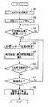
次に、お好み動作が選択された場合における本マッサージ機の動作について説明する。図7は、お好み動作が選択された場合における本マッサージ機の動作を示すフローチャートである。まず、ステップS1において、使用者により「お好み動作」ボタン44が押されると、手技設定部313は、お好み動作が選択されたと判定し、マッサージを施す部位を選択するための操作画像及び手技を選択するための操作画像を表示部323に表示させ、使用者により入力された操作指令に従って、マッサージを施す部位を設定すると共に、マッサージを行う手技を設定する。   Next, the operation of the massage machine when the favorite operation is selected will be described. FIG. 7 is a flowchart showing the operation of the massage machine when the favorite operation is selected. First, in step S1, when the “preferred action” button 44 is pressed by the user, the technique setting unit 313 determines that a favorite action has been selected, and an operation image and technique for selecting a part to be massaged. An operation image for selecting is displayed on the display unit 323, a part to be massaged is set according to an operation command input by the user, and a technique for performing massage is set.

次に、ステップS2において、特定部314は、マッサージ部300を駆動して施療子22を上下方向の下端位置U1から上端位置U2まで上下方向に移動させ、幅センサ301、上下センサ302、及び強弱センサ303による施療子22の位置の検出結果を取得し、取得した検出結果から使用者の体型情報を取得する。   Next, in step S2, the specifying unit 314 drives the massage unit 300 to move the treatment element 22 in the vertical direction from the lower end position U1 in the vertical direction to the upper end position U2, and the width sensor 301, the vertical sensor 302, and the strength The detection result of the position of the treatment element 22 by the sensor 303 is acquired, and the user's body shape information is acquired from the acquired detection result.

次に、ステップS3において、特定部314は、動作駆動制御部312を制御して、ステップS1で設定された部位及び手技に対して予め定められた手技開始位置に施療子22の移動を開始させ、施療子22が手技開始位置に到着ていない場合は(ステップS3でNO)、処理をステップS3に戻し、到着した場合は(ステップS3でYES)、動作駆動制御部312を制御して、ステップS1で設定された手技に対して予め定められた動作パターンに従って施療子22を駆動させる。ここで、特定部314は、目標マッサージ位置が定められた標準体型をステップS2で取得した体型情報から得られる使用者の体型にマッピングすることで、使用者における手技開始位置を求め、求めた手技開始位置に、施療子22を移動させる。   Next, in step S3, the specifying unit 314 controls the motion drive control unit 312 to start the movement of the treatment element 22 to the predetermined procedure start position for the part and procedure set in step S1. If the treatment element 22 has not arrived at the procedure start position (NO in step S3), the process returns to step S3. If it has arrived (YES in step S3), the operation drive control unit 312 is controlled to perform step The treatment element 22 is driven according to a predetermined operation pattern for the procedure set in S1. Here, the specifying unit 314 obtains a procedure start position in the user by mapping the standard figure with the target massage position determined to the figure of the user obtained from the figure information acquired in step S2, and obtains the procedure. The treatment element 22 is moved to the start position.

次に、ステップS4において、特定部314は、ステップS1で設定された手技に対して標準体型上において予め定められた目標マッサージ位置を位置記憶部316から特定し、センシングにより取得した体型情報から得られる使用者の体型に標準体型をマッピングすることで、マッサージ対象となる使用者の目標マッサージ位置を特定する。   Next, in step S4, the specifying unit 314 specifies a target massage position predetermined on the standard figure from the position storage unit 316 for the procedure set in step S1, and obtains it from the figure information acquired by sensing. The target body massage position of the user to be massaged is specified by mapping the standard body shape to the body shape of the user.

次に、表示制御部315は、ステップS1で設定された手技に対する体型画像G1を特定し、特定した体型画像G1にステップS4で特定した目標マッサージ位置を示す目印M1を付すと共に、マッサージ動作を行っている施療子22の位置を表示するための目印M2を付した画像を報知画像として表示部323に表示する(ステップS5)。また、このとき、表示制御部315は、ステップS1で設定された手技に対する関連情報画像を関連情報記憶部318から特定し、特定した関連情報画像を報知画像と併せて表示部323に表示する。   Next, the display control unit 315 identifies the body image G1 for the procedure set in step S1, attaches the mark M1 indicating the target massage position identified in step S4 to the identified body image G1, and performs a massage operation. An image with a mark M2 for displaying the position of the treatment element 22 is displayed on the display unit 323 as a notification image (step S5). At this time, the display control unit 315 specifies a related information image for the procedure set in step S1 from the related information storage unit 318, and displays the specified related information image together with the notification image on the display unit 323.

次に、ステップS6において、手技選択部322が現在設定されている手技とは別の手技を選択するための操作指令を受け付けた場合(ステップS6でYES)、手技設定部313は、選択された手技をマッサージを行う手技として設定し、処理をステップS4に戻す。   Next, in step S6, when the operation selection unit 322 receives an operation command for selecting a procedure different from the currently set procedure (YES in step S6), the procedure setting unit 313 is selected. The technique is set as a massage technique, and the process returns to step S4.

このとき、動作駆動制御部312は、新たに選択された手技に対する目標マッサージ位置に施療子22を移動させることなく、新たに選択された手技を実行するため、施療子22が新たに選択された手技の目標マッサージ位置をマッサージしない虞がある。しかしながら、本マッサージ機においては、表示制御部315は、図5(a)、(b)に示すような報知画像を表示部323に表示するため、使用者は、選択している手技の目標マッサージ位置を施療子22がマッサージしていないことを認識することが可能となる。また、この報知画像には、目標マッサージ位置を報知するための目印M1と、現在設定されている手技において使用者に最大の圧力が加わるポイント(凝りポイント)を示す目印M22と、施療子22の現在位置を示す目印M23とが含まれている。そのため、使用者は、位置調整部321を操作して、目印M1上に目印M22がくるように、施療子22の位置を調整し、高いマッサージ効果を得ることが可能となる。   At this time, since the operation drive control unit 312 performs the newly selected procedure without moving the therapy device 22 to the target massage position for the newly selected procedure, the therapy device 22 is newly selected. There is a possibility that the target massage position of the procedure is not massaged. However, in this massage machine, the display control unit 315 displays a notification image as shown in FIGS. 5A and 5B on the display unit 323, so that the user can perform target massage of the selected procedure. It becomes possible to recognize that the treatment element 22 is not massaging the position. Further, the notification image includes a mark M1 for notifying the target massage position, a mark M22 indicating a point (stiffness point) at which the maximum pressure is applied to the user in the currently set procedure, and the treatment element 22 A mark M23 indicating the current position is included. Therefore, the user can operate the position adjusting unit 321 to adjust the position of the treatment element 22 so that the mark M22 is positioned on the mark M1, thereby obtaining a high massage effect.

次に、ステップS6でNOと判定され、使用者により「急停止」ボタン48が押される等して、操作部320がマッサージを停止させるための操作指令を受け付けると(ステップS7でYES)、動作駆動制御部312は、施療子22の動作を停止させ、表示制御部315は、施療子22の現在位置を示す目印M2の表示を停止する(ステップS8)。一方、ステップS7でNOと判定された場合、処理はステップS4に戻され、マッサージが継続される。   Next, when it is determined NO in step S6 and the operation unit 320 receives an operation command for stopping the massage, for example, by pressing the “sudden stop” button 48 by the user (YES in step S7), the operation is performed. The drive control unit 312 stops the operation of the treatment element 22, and the display control unit 315 stops displaying the mark M2 indicating the current position of the treatment element 22 (step S8). On the other hand, when it determines with NO by step S7, a process is returned to step S4 and a massage is continued.

以上説明したように本マッサージ機によれば、使用者が選択した手技に対してマッサージ効果の高い位置である目標マッサージ位置が使用者に報知されるため、マッサージ効果の高い位置を使用者に認識させることができる。そのため、使用者は、施療子22を目標マッサージ位置に移動して選択した手技によるマッサージを実行することで、高いマッサージ効果を得ることができる。   As described above, according to the present massage machine, the user is notified of the target massage position, which is the position where the massage effect is high for the procedure selected by the user, so the user can recognize the position where the massage effect is high. Can be made. Therefore, the user can obtain a high massage effect by moving the treatment element 22 to the target massage position and performing massage by the selected procedure.

マッサージ機の外観構成図を示している。The external appearance block diagram of the massage machine is shown. 操作部の外観構成図を示している。The external appearance block diagram of the operation part is shown. マッサージ部の外観構成図を示している。The external appearance block diagram of the massage part is shown. 本マッサージ機の電気的な構成を示すブロック図である。It is a block diagram which shows the electrical structure of this massage machine. 表示制御部が表示部に表示する報知画像を示した図であり、(a)はある手技Aが設定された場合の報知画像を示し、(b)は手技Aとは異なる手技Bが設定された場合の報知画像を示している。It is the figure which showed the alerting | reporting image which a display control part displays on a display part, (a) shows the alerting | reporting image when a certain procedure A is set, (b) shows the procedure B different from the procedure A is set. In this case, a notification image is shown. (a)、(b)は関連情報画像を示した図である。(A), (b) is the figure which showed the related information image. お好み動作が選択された場合における本マッサージ機の動作を示すフローチャートである。It is a flowchart which shows operation | movement of this massage machine in case favorite action is selected.

符号の説明Explanation of symbols

300 マッサージ部
301 幅センサ
302 上下センサ
303 強弱センサ
304 幅駆動部
305 上下駆動部
306 強弱駆動部
310 制御部
312 動作駆動制御部
313 手技設定部
314 特定部
315 表示制御部
316 位置記憶部
317 体型画像記憶部
318 関連情報記憶部
319 記憶部
320 操作部
321 位置調整部
322 手技選択部
323 表示部
300 Massage unit 301 Width sensor 302 Vertical sensor 303 Strength sensor 304 Width drive unit 305 Vertical drive unit 306 Strength drive unit 310 Control unit 312 Operation drive control unit 313 Procedure setting unit 314 Identification unit 315 Display control unit 316 Position storage unit 317 Body image Storage unit 318 Related information storage unit 319 Storage unit 320 Operation unit 321 Position adjustment unit 322 Procedure selection unit 323 Display unit

Claims (4)

背もたれ部に配設された施療子が、3次元的に移動することで所定の手技を前記背もたれ部の任意の位置で行うマッサージ機であって、
使用者の操作指令に従って手技を設定する手技設定手段と、
使用者の操作指令に従って、前記施療子の位置を調節すると共に、前記手技設定手段により設定された手技に対して予め定められた動作パターンに従って前記施療子を駆動する駆動手段と、
前記手技設定手段により設定された手技に対して予め定められたマッサージ効果の高い位置を使用者に報知する報知手段とを備えることを特徴とするマッサージ機。
The treatment element disposed in the backrest part is a massage machine that performs a predetermined procedure at an arbitrary position of the backrest part by moving three-dimensionally,
A procedure setting means for setting a procedure according to a user's operation command;
A drive unit that adjusts the position of the treatment element according to a user's operation command and drives the treatment element according to a predetermined operation pattern for the procedure set by the procedure setting unit;
A massage machine comprising: an informing means for notifying a user of a position having a high massage effect predetermined for the technique set by the technique setting means.
前記駆動手段により駆動されている施療子の現在位置を検出する位置検出手段を更に備え、
前記報知手段は、マッサージ効果の高い位置に加えて、前記位置検出手段により検出された施療子の現在位置を報知することを特徴とする請求項1記載のマッサージ機。
Further comprising position detecting means for detecting the current position of the treatment element driven by the driving means;
2. The massage machine according to claim 1, wherein the notifying unit notifies a current position of the treatment element detected by the position detecting unit in addition to a position having a high massage effect.
前記報知手段は、複数の方向から人間の体型を表す体型画像の中から、前記手技設定手段により設定された手技により動作する施療子の動作の特徴を良く表すことのできる方向から人間を見たときの体型画像上に、マッサージ効果の高い位置を示すと共に、施療子の現在位置とを示す画像を表示部に表示することを特徴とする請求項2記載のマッサージ機。   The informing means sees a person from a direction that can well represent the characteristics of the operation of the treatment element operated by the technique set by the technique setting means, from among the body shape images representing the human figure from a plurality of directions. The massage machine according to claim 2, wherein an image showing a position having a high massage effect and a current position of the treatment element is displayed on the display on the body shape image. 前記報知手段は、前記手技設定手段により設定された手技に関連するツボの位置と、前記手技による効能とを報知することを特徴とする請求項1〜3のいずれか1項に記載のマッサージ機。   The massage machine according to any one of claims 1 to 3, wherein the notifying unit notifies the position of the acupuncture point related to the procedure set by the procedure setting unit and the efficacy of the procedure. .
JP2007016100A 2007-01-26 2007-01-26 Massage machine Expired - Fee Related JP4697151B2 (en)

Priority Applications (1)

Application Number Priority Date Filing Date Title
JP2007016100A JP4697151B2 (en) 2007-01-26 2007-01-26 Massage machine

Applications Claiming Priority (1)

Application Number Priority Date Filing Date Title
JP2007016100A JP4697151B2 (en) 2007-01-26 2007-01-26 Massage machine

Publications (2)

Publication Number Publication Date
JP2008178633A JP2008178633A (en) 2008-08-07
JP4697151B2 true JP4697151B2 (en) 2011-06-08

Family

ID=39722973

Family Applications (1)

Application Number Title Priority Date Filing Date
JP2007016100A Expired - Fee Related JP4697151B2 (en) 2007-01-26 2007-01-26 Massage machine

Country Status (1)

Country Link
JP (1) JP4697151B2 (en)

Families Citing this family (3)

* Cited by examiner, † Cited by third party
Publication number Priority date Publication date Assignee Title
KR200471611Y1 (en) 2011-12-07 2014-03-05 주식회사 휴테크산업 A Massager
JP2014094022A (en) * 2012-11-07 2014-05-22 Panasonic Corp Image display program, electronic device, massage device, and massage system
JP6795171B2 (en) * 2016-06-22 2020-12-02 ファミリーイナダ株式会社 Massage machine

Citations (4)

* Cited by examiner, † Cited by third party
Publication number Priority date Publication date Assignee Title
JP2001161767A (en) * 1999-12-03 2001-06-19 Family Kk Massage machine, and operating device for massage machine
JP2002369860A (en) * 2001-06-14 2002-12-24 Matsushita Electric Works Ltd Operation unit for massage machine
JP2005342340A (en) * 2004-06-04 2005-12-15 Matsushita Electric Works Ltd Massage machine
JP2007007207A (en) * 2005-06-30 2007-01-18 Fuji Iryoki:Kk Massage machine

Family Cites Families (1)

* Cited by examiner, † Cited by third party
Publication number Priority date Publication date Assignee Title
JP3059578B2 (en) * 1992-06-18 2000-07-04 松下電工株式会社 Massage machine

Patent Citations (4)

* Cited by examiner, † Cited by third party
Publication number Priority date Publication date Assignee Title
JP2001161767A (en) * 1999-12-03 2001-06-19 Family Kk Massage machine, and operating device for massage machine
JP2002369860A (en) * 2001-06-14 2002-12-24 Matsushita Electric Works Ltd Operation unit for massage machine
JP2005342340A (en) * 2004-06-04 2005-12-15 Matsushita Electric Works Ltd Massage machine
JP2007007207A (en) * 2005-06-30 2007-01-18 Fuji Iryoki:Kk Massage machine

Also Published As

Publication number Publication date
JP2008178633A (en) 2008-08-07

Similar Documents

Publication Publication Date Title
TWI682774B (en) Seat massage chair
JP4651556B2 (en) Massage machine
JP2017051427A (en) Walking training device
JP2008049088A (en) Massaging machine
JP4697151B2 (en) Massage machine
TWI731938B (en) Massage machine and control method of massage machine
JP4509987B2 (en) Chair type massage device
JP2002369846A (en) Massage machine
JP2005006735A (en) Massage machine
JP4791052B2 (en) Massage machine
JP4851157B2 (en) Massage machine
JP4938183B2 (en) Massage machine
JP3400754B2 (en) Chair type massage machine
JPH11178877A (en) Massager
JP4481221B2 (en) Remote control device for chair type massage machine and chair type massage machine provided with the same
JP2019092898A (en) Massage machine
JP5268560B2 (en) Chair massage machine
JP4752776B2 (en) Massage machine
JP4723120B2 (en) Massage machine
JP2021078603A (en) Massage system
JP4598560B2 (en) Massage machine
JP7351605B2 (en) Massage machine
JP5806522B2 (en) Massage machine
JP4805650B2 (en) Massage machine
JP6238941B2 (en) Massage machine

Legal Events

Date Code Title Description
A621 Written request for application examination

Free format text: JAPANESE INTERMEDIATE CODE: A621

Effective date: 20090515

A977 Report on retrieval

Free format text: JAPANESE INTERMEDIATE CODE: A971007

Effective date: 20110113

TRDD Decision of grant or rejection written
A01 Written decision to grant a patent or to grant a registration (utility model)

Free format text: JAPANESE INTERMEDIATE CODE: A01

Effective date: 20110201

A61 First payment of annual fees (during grant procedure)

Free format text: JAPANESE INTERMEDIATE CODE: A61

Effective date: 20110214

R150 Certificate of patent or registration of utility model

Ref document number: 4697151

Country of ref document: JP

Free format text: JAPANESE INTERMEDIATE CODE: R150

LAPS Cancellation because of no payment of annual fees