JP4696147B2 - Turbo machine - Google Patents
Turbo machine Download PDFInfo
- Publication number
- JP4696147B2 JP4696147B2 JP2008169773A JP2008169773A JP4696147B2 JP 4696147 B2 JP4696147 B2 JP 4696147B2 JP 2008169773 A JP2008169773 A JP 2008169773A JP 2008169773 A JP2008169773 A JP 2008169773A JP 4696147 B2 JP4696147 B2 JP 4696147B2
- Authority
- JP
- Japan
- Prior art keywords
- rotor
- segments
- labyrinth seal
- turbomachine
- comb
- Prior art date
- Legal status (The legal status is an assumption and is not a legal conclusion. Google has not performed a legal analysis and makes no representation as to the accuracy of the status listed.)
- Expired - Fee Related
Links
Images
Classifications
-
- F—MECHANICAL ENGINEERING; LIGHTING; HEATING; WEAPONS; BLASTING
- F04—POSITIVE - DISPLACEMENT MACHINES FOR LIQUIDS; PUMPS FOR LIQUIDS OR ELASTIC FLUIDS
- F04D—NON-POSITIVE-DISPLACEMENT PUMPS
- F04D29/00—Details, component parts, or accessories
- F04D29/08—Sealings
- F04D29/10—Shaft sealings
- F04D29/102—Shaft sealings especially adapted for elastic fluid pumps
-
- F—MECHANICAL ENGINEERING; LIGHTING; HEATING; WEAPONS; BLASTING
- F01—MACHINES OR ENGINES IN GENERAL; ENGINE PLANTS IN GENERAL; STEAM ENGINES
- F01D—NON-POSITIVE DISPLACEMENT MACHINES OR ENGINES, e.g. STEAM TURBINES
- F01D11/00—Preventing or minimising internal leakage of working-fluid, e.g. between stages
- F01D11/001—Preventing or minimising internal leakage of working-fluid, e.g. between stages for sealing space between stator blade and rotor
-
- F—MECHANICAL ENGINEERING; LIGHTING; HEATING; WEAPONS; BLASTING
- F01—MACHINES OR ENGINES IN GENERAL; ENGINE PLANTS IN GENERAL; STEAM ENGINES
- F01D—NON-POSITIVE DISPLACEMENT MACHINES OR ENGINES, e.g. STEAM TURBINES
- F01D11/00—Preventing or minimising internal leakage of working-fluid, e.g. between stages
- F01D11/02—Preventing or minimising internal leakage of working-fluid, e.g. between stages by non-contact sealings, e.g. of labyrinth type
-
- F—MECHANICAL ENGINEERING; LIGHTING; HEATING; WEAPONS; BLASTING
- F01—MACHINES OR ENGINES IN GENERAL; ENGINE PLANTS IN GENERAL; STEAM ENGINES
- F01D—NON-POSITIVE DISPLACEMENT MACHINES OR ENGINES, e.g. STEAM TURBINES
- F01D11/00—Preventing or minimising internal leakage of working-fluid, e.g. between stages
- F01D11/08—Preventing or minimising internal leakage of working-fluid, e.g. between stages for sealing space between rotor blade tips and stator
-
- F—MECHANICAL ENGINEERING; LIGHTING; HEATING; WEAPONS; BLASTING
- F16—ENGINEERING ELEMENTS AND UNITS; GENERAL MEASURES FOR PRODUCING AND MAINTAINING EFFECTIVE FUNCTIONING OF MACHINES OR INSTALLATIONS; THERMAL INSULATION IN GENERAL
- F16J—PISTONS; CYLINDERS; SEALINGS
- F16J15/00—Sealings
- F16J15/44—Free-space packings
- F16J15/441—Free-space packings with floating ring
-
- F—MECHANICAL ENGINEERING; LIGHTING; HEATING; WEAPONS; BLASTING
- F16—ENGINEERING ELEMENTS AND UNITS; GENERAL MEASURES FOR PRODUCING AND MAINTAINING EFFECTIVE FUNCTIONING OF MACHINES OR INSTALLATIONS; THERMAL INSULATION IN GENERAL
- F16J—PISTONS; CYLINDERS; SEALINGS
- F16J15/00—Sealings
- F16J15/44—Free-space packings
- F16J15/447—Labyrinth packings
- F16J15/4472—Labyrinth packings with axial path
-
- F—MECHANICAL ENGINEERING; LIGHTING; HEATING; WEAPONS; BLASTING
- F05—INDEXING SCHEMES RELATING TO ENGINES OR PUMPS IN VARIOUS SUBCLASSES OF CLASSES F01-F04
- F05D—INDEXING SCHEME FOR ASPECTS RELATING TO NON-POSITIVE-DISPLACEMENT MACHINES OR ENGINES, GAS-TURBINES OR JET-PROPULSION PLANTS
- F05D2250/00—Geometry
- F05D2250/10—Two-dimensional
- F05D2250/18—Two-dimensional patterned
- F05D2250/182—Two-dimensional patterned crenellated, notched
-
- Y—GENERAL TAGGING OF NEW TECHNOLOGICAL DEVELOPMENTS; GENERAL TAGGING OF CROSS-SECTIONAL TECHNOLOGIES SPANNING OVER SEVERAL SECTIONS OF THE IPC; TECHNICAL SUBJECTS COVERED BY FORMER USPC CROSS-REFERENCE ART COLLECTIONS [XRACs] AND DIGESTS
- Y10—TECHNICAL SUBJECTS COVERED BY FORMER USPC
- Y10T—TECHNICAL SUBJECTS COVERED BY FORMER US CLASSIFICATION
- Y10T29/00—Metal working
- Y10T29/49—Method of mechanical manufacture
- Y10T29/49229—Prime mover or fluid pump making
- Y10T29/49297—Seal or packing making
-
- Y—GENERAL TAGGING OF NEW TECHNOLOGICAL DEVELOPMENTS; GENERAL TAGGING OF CROSS-SECTIONAL TECHNOLOGIES SPANNING OVER SEVERAL SECTIONS OF THE IPC; TECHNICAL SUBJECTS COVERED BY FORMER USPC CROSS-REFERENCE ART COLLECTIONS [XRACs] AND DIGESTS
- Y10—TECHNICAL SUBJECTS COVERED BY FORMER USPC
- Y10T—TECHNICAL SUBJECTS COVERED BY FORMER US CLASSIFICATION
- Y10T29/00—Metal working
- Y10T29/49—Method of mechanical manufacture
- Y10T29/49316—Impeller making
- Y10T29/4932—Turbomachine making
Landscapes
- Engineering & Computer Science (AREA)
- General Engineering & Computer Science (AREA)
- Mechanical Engineering (AREA)
- Turbine Rotor Nozzle Sealing (AREA)
- Sealing Using Fluids, Sealing Without Contact, And Removal Of Oil (AREA)
Description
本発明はターボ機械に係り、特に高速回転時におけるロータの不安定振動の防止に好適なターボ機械に関する。 The present invention relates to a turbomachine, and more particularly to a turbomachine suitable for preventing unstable vibration of a rotor during high-speed rotation.
ターボ機械は主に、回転羽根車を有するロータと、ロータを保持し、流路を形成するステータで構成されている。ステータとロータ間には間隙があり、この間隙からの流体漏洩を低減するために櫛歯構造のラビリンスシールが使用されることが多い。 A turbomachine is mainly composed of a rotor having a rotating impeller and a stator that holds the rotor and forms a flow path. There is a gap between the stator and the rotor, and a labyrinth seal having a comb-tooth structure is often used to reduce fluid leakage from the gap.
ロータを高速回転させると、ラビリンスシールの櫛歯間に形成される溝部に流体の旋回流れが発生するため、ロータに不安定振動が発生することがある。不安定振動を防止するためには、上記溝部における流体の旋回流速を低減することが有効である。例えば特開平10−61407号公報の図1に開示されているように、ラビリンスシールの流体入口側に案内羽根を設置し、流体の旋回流速を低減する構造が考案されている。 When the rotor is rotated at a high speed, a fluid swirl flow is generated in the groove formed between the comb teeth of the labyrinth seal, so that unstable vibration may occur in the rotor. In order to prevent unstable vibration, it is effective to reduce the swirling flow velocity of the fluid in the groove. For example, as disclosed in FIG. 1 of JP-A-10-61407, a structure has been devised in which guide vanes are installed on the fluid inlet side of the labyrinth seal to reduce the swirling flow velocity of the fluid.
一方、上記の不安定振動と類似の現象として、すべり軸受における潤滑油の旋回流れに起因するオイルホイップという現象がある。オイルホイップは真円軸受において発生しやすく、楕円軸受や多円弧軸受を採用することにより不安定振動が発生しにくくなることが知られている。 On the other hand, as a phenomenon similar to the above-described unstable vibration, there is a phenomenon called oil whip caused by a swirling flow of lubricating oil in a sliding bearing. Oil whip is easily generated in a perfect circle bearing, and it is known that unstable vibration is less likely to occur by using an elliptical bearing or a multi-arc bearing.
例えば特許文献1の図1に開示されたラビリンスシールにおいて、流体の旋回流速を低減する案内羽根の構造は複雑であるため、製作に手間がかかり、製造コストが高くなるという問題がある。 For example, in the labyrinth seal disclosed in FIG. 1 of Patent Document 1, the structure of the guide vane for reducing the swirling flow velocity of the fluid is complicated, so that there is a problem that it takes time to manufacture and the manufacturing cost increases.
本発明の目的は、製作が容易で、ロータの不安定振動を防止できるラビリンスシールを有するターボ機械を提供することにある。 An object of the present invention is to provide a turbo machine having a labyrinth seal that is easy to manufacture and can prevent unstable vibration of a rotor.
上記の目的を達成するために、本発明に係るターボ機械は、回転羽根車を有するロータ
と、ロータを保持し、流路を形成するステータと、該ステータとロータ間における流体漏
洩を低減する櫛歯構造のラビリンスシールを有するターボ機械において、円周方向にセグ
メント分割し、櫛歯高さの異なるセグメントを組み合わせて溝部底部に段差を形成したラビリンスシールを有することを特徴とするものである。
In order to achieve the above object, a turbomachine according to the present invention includes a rotor having a rotating impeller, a stator that holds the rotor and forms a flow path, and a comb that reduces fluid leakage between the stator and the rotor. A turbo machine having a labyrinth seal having a tooth structure has a labyrinth seal in which a segment is divided in the circumferential direction and a step is formed at the bottom of a groove by combining segments having different comb tooth heights.
そして、好ましくは、櫛歯高さの異なる2種類のセグメントを有し、回転軸直角断面上のある基準方向とその反対方向に櫛歯高さの高いセグメントを配置し、前記基準方向に直角な方向とその反対方向に櫛歯高さの低いセグメントを配置したラビリンスシールを有することを特徴とするものである。 Preferably, it has two types of segments having different comb tooth heights, and a segment having a high comb tooth height is disposed in a direction opposite to the reference direction on the cross section perpendicular to the rotation axis and the opposite direction, and is perpendicular to the reference direction. It has a labyrinth seal in which segments having a low comb tooth height are arranged in the opposite direction.
本発明によれば、製作が容易で、ラビリンスシールにおける流体の旋回流速を低減でき、ロータの不安定振動を防止できる。
According to the present invention, manufacturing is easy, the swirling flow velocity of the fluid in the labyrinth seal can be reduced, and unstable vibration of the rotor can be prevented.
以下に、本発明を実施するための最良の形態を、図面を用いて説明する。 The best mode for carrying out the present invention will be described below with reference to the drawings.
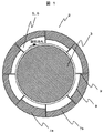
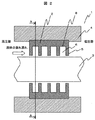
図1に本発明のターボ機械1の一実施例におけるラビリンスシール2の軸直角断面図を、図2に本実施例のターボ機械1の要部断面図を示す。
FIG. 1 shows a cross-sectional view perpendicular to the axis of a
図2に示すように、本実施例のターボ機械1は、図示しない回転羽根車を有し、高速回転するロータ3と、ロータ3を保持し、図示しない流路を形成するステータ4を有している。ターボ機械1には一般的に高圧部と低圧部が存在するので、ステータ4とロータ3間の間隙には、高圧部から低圧部への流体の漏れ流れが発生する。この漏れ流れを低減するために櫛歯5構造のラビリンスシール2を有している。
As shown in FIG. 2, the turbomachine 1 of this embodiment has a rotating impeller (not shown), a
図1は図2のA−A断面図である。ラビリンスシール2入口の旋回流れや、ロータ3の回転に伴うつれまわりにより、ラビリンスシール2の櫛歯5間に形成された溝部6内には旋回流れが発生する。
1 is a cross-sectional view taken along line AA of FIG. A swirling flow is generated in the
本実施例におけるラビリンスシール2は、円周方向に、8個のセグメント7に分割されており、櫛歯5高さの高いセグメント7aと櫛歯5高さの低いセグメント7bを交互に並んで配置している。旋回流れが溝部6底部8の段差9を通過するため、流路抵抗が増加し、旋回流速が小さくなる。また、櫛歯5の高さの異なる2種類のラビリンスシール2をリング状に製作し、このリングを分割して組み合わせることにより製作できるので、案内羽根などを製作する場合と比較して、製作が容易である。
The
なお、ラビリンスシール2の円周方向分割数は複数であれば何個でもよい。櫛歯5高さの高いセグメント7aと櫛歯5高さの低いセグメント7bの配置は交互でなくてもよい。櫛歯5の高さが異なるセグメント7の並びを複数有するのがよい。
The number of circumferential divisions of the
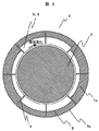
図3に本発明のターボ機械の他の実施例におけるラビリンスシール2の軸直角断面図を示す。本実施例のラビリンスシール2は、円周方向に、8個のセグメント7に分割されている。上下それぞれ2個のセグメント7の櫛歯5高さが高く、左右それぞれ2個のセグメント7の櫛歯5高さが低くなっている。すなわち、上方向を基準方向とすると、基準方向である上方向とその反対方向である下方向に櫛歯5高さの高いセグメント7aを配置し、基準方向に直角な右方向とその反対の左方向に櫛歯5高さの低いセグメント7bを配置している。上下方向を櫛歯5高さの高い長軸,左右方向を櫛歯5高さの低い短軸と考えると、溝部6底部8を楕円形状としたことと類似の効果が得られることがわかる。このため、楕円軸受採用によるオイルホイップ防止効果と同様の効果で、ロータ3の不安定振動を防止できる。
FIG. 3 is a cross-sectional view perpendicular to the axis of the
以上の記載によれば、本実施例におけるターボ機械は、櫛歯高さの異なるセグメントを組み合わせたラビリンスシールを有することにより、ラビリンスシールの溝部の外周面に段差ができるため、ラビリンスシールにおける流体の旋回流速を低減でき、ロータの不安定振動を防止できる。また、櫛歯の高さの異なる複数種類のラビリンスシールをリング状に製作し、このリングを分割して組み合わせることによりラビリンスシールを製作できるので、製作が容易である。 According to the above description, since the turbo machine in the present embodiment has a labyrinth seal in which segments having different comb tooth heights are combined, a step can be formed on the outer peripheral surface of the groove portion of the labyrinth seal. The turning flow velocity can be reduced, and unstable vibration of the rotor can be prevented. Moreover, since the labyrinth seal can be manufactured by manufacturing a plurality of types of labyrinth seals having different comb tooth heights in a ring shape and combining the rings, the manufacturing is easy.
また、櫛歯高さの異なる2種類のセグメントを有し、回転軸直角断面上のある基準方向とその反対方向に櫛歯高さの高いセグメントを配置し、前記基準方向に直角な方向とその反対方向に櫛歯高さの低いセグメントを配置することにより、ラビリンスシール溝部外周面の回転軸直角断面形状に櫛歯高さの高い長軸と櫛歯高さの低い短軸が形成されるため、楕円軸受採用によるオイルホイップ防止効果と同様の効果で、ロータの不安定振動を防止できる。 In addition, there are two types of segments having different comb tooth heights, a segment having a high comb tooth height is arranged in a direction opposite to the reference direction on the cross section perpendicular to the rotation axis, and a direction perpendicular to the reference direction. By arranging a segment with a low comb tooth height in the opposite direction, a long axis with a high comb tooth height and a short axis with a low comb tooth height are formed in the cross-sectional shape perpendicular to the rotation axis of the labyrinth seal groove outer peripheral surface. With the same effect as the oil whip prevention effect by adopting the elliptical bearing, the unstable vibration of the rotor can be prevented.
1 ターボ機械
2 ラビリンスシール
3 ロータ
4 ステータ
5 櫛歯
6 溝部
7 セグメント
7a 櫛歯高さの高いセグメント
7b 櫛歯高さの低いセグメント
8 溝部底部
9 溝部底部の段差
DESCRIPTION OF SYMBOLS 1
Claims (3)
ータと前記ロータ間における流体漏洩を低減する櫛歯構造のラビリンスシールと、を有す
るターボ機械において、前記ラビリンスシールは、円周方向にセグメントに分かれていて
、櫛歯高さの異なるセグメントを組み合わせて溝部底部に段差を形成したことを特徴とするターボ機械。 In the turbomachine having a rotor having a rotating impeller, a stator holding the rotor and forming a flow path, and a labyrinth seal having a comb-tooth structure for reducing fluid leakage between the stator and the rotor, the labyrinth seal Is a turbomachine characterized in that a step is formed at the bottom of the groove by combining segments with different comb tooth heights, which are divided into segments in the circumferential direction.
ータと前記ロータ間における流体漏洩を低減する櫛歯構造のラビリンスシールと、を有す
るターボ機械において、前記ラビリンスシールは、円周方向にセグメントに分かれていて
、櫛歯高さの異なる2種類の前記セグメントを有し、前記ロータの直角断面上のある基準方向及びその反対方向に櫛歯高さの高いセグメントを配置し、前記基準方向に直角な方向とその反対方向に櫛歯高さの低いセグメントを配置したラビリンスシールを有するターボ機械。 A rotor having a rotating impeller, a stator that holds the rotor and forms a flow path, and the stator
And a labyrinth seal with a comb-tooth structure that reduces fluid leakage between the rotor and the rotor.
In the turbo machine, the labyrinth seal is divided into segments in the circumferential direction.
Has two said segments having different comb tooth heights, the higher segments of comb tooth height to the reference direction and the opposite direction is on the normal plane of the rotor are arranged, and the direction perpendicular to the reference direction A turbomachine having a labyrinth seal in which segments having low comb teeth are arranged in the opposite direction.
が並んで配置しているターボ機械。 The turbomachine according to claim 1, wherein the segments are arranged such that segments having different comb tooth heights are arranged side by side.
Priority Applications (3)
| Application Number | Priority Date | Filing Date | Title |
|---|---|---|---|
| JP2008169773A JP4696147B2 (en) | 2008-06-30 | 2008-06-30 | Turbo machine |
| US12/491,391 US8388311B2 (en) | 2008-06-30 | 2009-06-25 | Turbomachinery |
| EP09164093A EP2141363B1 (en) | 2008-06-30 | 2009-06-30 | Seal for turbomachine |
Applications Claiming Priority (1)
| Application Number | Priority Date | Filing Date | Title |
|---|---|---|---|
| JP2008169773A JP4696147B2 (en) | 2008-06-30 | 2008-06-30 | Turbo machine |
Publications (2)
| Publication Number | Publication Date |
|---|---|
| JP2010007611A JP2010007611A (en) | 2010-01-14 |
| JP4696147B2 true JP4696147B2 (en) | 2011-06-08 |
Family
ID=40873232
Family Applications (1)
| Application Number | Title | Priority Date | Filing Date |
|---|---|---|---|
| JP2008169773A Expired - Fee Related JP4696147B2 (en) | 2008-06-30 | 2008-06-30 | Turbo machine |
Country Status (3)
| Country | Link |
|---|---|
| US (1) | US8388311B2 (en) |
| EP (1) | EP2141363B1 (en) |
| JP (1) | JP4696147B2 (en) |
Families Citing this family (16)
| Publication number | Priority date | Publication date | Assignee | Title |
|---|---|---|---|---|
| JP5147885B2 (en) | 2010-03-26 | 2013-02-20 | 株式会社日立製作所 | Rotor vibration preventing structure and steam turbine using the same |
| GB2480680B (en) * | 2010-05-28 | 2012-10-03 | Alstom Technology Ltd | Labyrinth seal |
| JP2012102831A (en) * | 2010-11-12 | 2012-05-31 | Hitachi Ltd | Labyrinth seal device and turbo machine using the same |
| JP2014020509A (en) * | 2012-07-20 | 2014-02-03 | Toshiba Corp | Seal device, axial flow turbine, and power-generating plant |
| JP6049385B2 (en) * | 2012-10-04 | 2016-12-21 | 株式会社日立製作所 | Centrifugal compressor |
| JP5931708B2 (en) * | 2012-12-04 | 2016-06-08 | 三菱重工業株式会社 | Sealing device and rotating machine |
| CN103090012A (en) * | 2013-01-18 | 2013-05-08 | 沈阳航空航天大学 | Novel high stability dislocation four gas wedge seal structure |
| US9574453B2 (en) * | 2014-01-02 | 2017-02-21 | General Electric Company | Steam turbine and methods of assembling the same |
| US9359908B2 (en) | 2014-07-08 | 2016-06-07 | General Electric Company | Film riding seal assembly for turbomachinery |
| US10161259B2 (en) | 2014-10-28 | 2018-12-25 | General Electric Company | Flexible film-riding seal |
| GB201715169D0 (en) | 2017-09-20 | 2017-11-01 | Rolls Royce Plc | Seal for a gas turbine |
| US20190195072A1 (en) * | 2017-12-22 | 2019-06-27 | Rolls-Royce North American Technologies Inc. | Turbine rotor disc having multiple rims |
| CN108331783A (en) * | 2018-02-24 | 2018-07-27 | 西安交通大学 | A kind of orthotropy rotary seal structure |
| JP6846374B2 (en) * | 2018-03-08 | 2021-03-24 | 三菱重工業株式会社 | Moving wing side sealing device, stationary wing side sealing device and rotating machine |
| CN110439631B (en) * | 2019-08-21 | 2024-05-28 | 沈阳航空航天大学 | Labyrinth sealing structure capable of controlling active clearance |
| CN115021459A (en) * | 2022-05-30 | 2022-09-06 | 江苏中工高端装备研究院有限公司 | High-reliability dustproof sealing structure for annular permanent magnet synchronous motor |
Family Cites Families (11)
| Publication number | Priority date | Publication date | Assignee | Title |
|---|---|---|---|---|
| FR852718A (en) * | 1938-10-21 | 1940-03-01 | Automobiles Soc Nouv | Improvements to heavy oil or other fuel engines |
| JPS56148152U (en) * | 1980-04-07 | 1981-11-07 | ||
| IT1152732B (en) | 1982-10-19 | 1987-01-07 | Nuovo Pignone Spa | PERFECTED LABYRINTH SEAL |
| JPS633570U (en) * | 1986-06-26 | 1988-01-11 | ||
| JPS63293365A (en) * | 1987-05-27 | 1988-11-30 | Hitachi Plant Eng & Constr Co Ltd | Labyrinth packing equipment |
| JPH05195707A (en) * | 1992-01-17 | 1993-08-03 | Mitsubishi Heavy Ind Ltd | Shaft sealing device of turbine rotor |
| JP3492101B2 (en) | 1996-08-16 | 2004-02-03 | 三菱重工業株式会社 | Swirl prevention device for fluid machinery |
| US7004475B2 (en) * | 2003-09-26 | 2006-02-28 | Siemens Westinghouse Power Corporation | Flow dam design for labyrinth seals to promote rotor stability |
| JP2005214144A (en) * | 2004-01-30 | 2005-08-11 | Toshiba Corp | Swirl flow prevention device for fluid machinery |
| FR2893357B1 (en) | 2005-11-15 | 2011-05-06 | Snecma | ANNULAR LETTER FOR SEALING LABYRINTH AND METHOD OF MANUFACTURING THE SAME |
| FR2930593B1 (en) * | 2008-04-23 | 2013-05-31 | Snecma | THERMOMECHANICAL ROOM FOR REVOLUTION AROUND A LONGITUDINAL AXIS, COMPRISING AT LEAST ONE ABRADABLE CROWN FOR A SEALING LABYRINTH |
-
2008
- 2008-06-30 JP JP2008169773A patent/JP4696147B2/en not_active Expired - Fee Related
-
2009
- 2009-06-25 US US12/491,391 patent/US8388311B2/en not_active Expired - Fee Related
- 2009-06-30 EP EP09164093A patent/EP2141363B1/en not_active Not-in-force
Also Published As
| Publication number | Publication date |
|---|---|
| EP2141363B1 (en) | 2012-08-01 |
| EP2141363A3 (en) | 2010-11-03 |
| US8388311B2 (en) | 2013-03-05 |
| US20100166544A1 (en) | 2010-07-01 |
| EP2141363A2 (en) | 2010-01-06 |
| JP2010007611A (en) | 2010-01-14 |
Similar Documents
| Publication | Publication Date | Title |
|---|---|---|
| JP4696147B2 (en) | Turbo machine | |
| JP6198200B2 (en) | Rotating machine | |
| US10281046B2 (en) | Fluid machine having a labyrinth seal | |
| JP5524427B2 (en) | Thrust bearing device for turbocharger | |
| JP5922796B2 (en) | Sealing device and rotating machine | |
| JP2012087929A (en) | Labyrinth seal system | |
| JP5993032B2 (en) | Rotating fluid machine | |
| KR102020138B1 (en) | Labyrinth Seal | |
| JP5972374B2 (en) | Axial fluid machine | |
| WO2015115558A1 (en) | Seal structure and rotating machine | |
| JP5643245B2 (en) | Turbo machine | |
| JP2016089768A (en) | Sealing device and turbomachine | |
| CN108368745B (en) | Seal structure and turbine | |
| RU2011112993A (en) | ROTOR AND SEALING DEVICE FOR ROTARY MACHINE | |
| JPWO2016030952A1 (en) | Sealing mechanism, rotating machine | |
| JP2019157662A (en) | Rotor blade side seal device, stator blade side seal device and rotary machine | |
| JP2006138259A (en) | Axial flow turbine | |
| EP3056667A2 (en) | Turbine bucket for control of wheelspace purge air | |
| JP2017227259A (en) | Labyrinth seal | |
| JP6204757B2 (en) | Fluid machinery | |
| JP2017155625A5 (en) | ||
| JP2011163421A (en) | Labyrinth seal device for turbomachine | |
| CN105318011B (en) | Low-leakage-rate F type staggered tooth labyrinth seal capable of adapting to vibration of rotor | |
| CN205207690U (en) | Crisscross tooth labyrinth seals of low leakage F type that can adapt to rotor oscillation | |
| JP5694128B2 (en) | Steam turbine |
Legal Events
| Date | Code | Title | Description |
|---|---|---|---|
| A621 | Written request for application examination |
Free format text: JAPANESE INTERMEDIATE CODE: A621 Effective date: 20100311 |
|
| A977 | Report on retrieval |
Free format text: JAPANESE INTERMEDIATE CODE: A971007 Effective date: 20100609 |
|
| A131 | Notification of reasons for refusal |
Free format text: JAPANESE INTERMEDIATE CODE: A131 Effective date: 20100615 |
|
| A521 | Request for written amendment filed |
Free format text: JAPANESE INTERMEDIATE CODE: A523 Effective date: 20100809 |
|
| TRDD | Decision of grant or rejection written | ||
| A01 | Written decision to grant a patent or to grant a registration (utility model) |
Free format text: JAPANESE INTERMEDIATE CODE: A01 Effective date: 20110201 |
|
| A01 | Written decision to grant a patent or to grant a registration (utility model) |
Free format text: JAPANESE INTERMEDIATE CODE: A01 |
|
| A61 | First payment of annual fees (during grant procedure) |
Free format text: JAPANESE INTERMEDIATE CODE: A61 Effective date: 20110228 |
|
| FPAY | Renewal fee payment (event date is renewal date of database) |
Free format text: PAYMENT UNTIL: 20140304 Year of fee payment: 3 |
|
| R250 | Receipt of annual fees |
Free format text: JAPANESE INTERMEDIATE CODE: R250 |
|
| S111 | Request for change of ownership or part of ownership |
Free format text: JAPANESE INTERMEDIATE CODE: R313111 |
|
| R350 | Written notification of registration of transfer |
Free format text: JAPANESE INTERMEDIATE CODE: R350 |
|
| R250 | Receipt of annual fees |
Free format text: JAPANESE INTERMEDIATE CODE: R250 |
|
| R250 | Receipt of annual fees |
Free format text: JAPANESE INTERMEDIATE CODE: R250 |
|
| R250 | Receipt of annual fees |
Free format text: JAPANESE INTERMEDIATE CODE: R250 |
|
| LAPS | Cancellation because of no payment of annual fees |