JP4691237B2 - Vibration type compressor - Google Patents
Vibration type compressor Download PDFInfo
- Publication number
- JP4691237B2 JP4691237B2 JP2000325224A JP2000325224A JP4691237B2 JP 4691237 B2 JP4691237 B2 JP 4691237B2 JP 2000325224 A JP2000325224 A JP 2000325224A JP 2000325224 A JP2000325224 A JP 2000325224A JP 4691237 B2 JP4691237 B2 JP 4691237B2
- Authority
- JP
- Japan
- Prior art keywords
- magnet
- electromagnetic coil
- cylindrical
- core pole
- piston
- Prior art date
- Legal status (The legal status is an assumption and is not a legal conclusion. Google has not performed a legal analysis and makes no representation as to the accuracy of the status listed.)
- Expired - Lifetime
Links
Images


Classifications
-
- H—ELECTRICITY
- H02—GENERATION; CONVERSION OR DISTRIBUTION OF ELECTRIC POWER
- H02K—DYNAMO-ELECTRIC MACHINES
- H02K33/00—Motors with reciprocating, oscillating or vibrating magnet, armature or coil system
- H02K33/18—Motors with reciprocating, oscillating or vibrating magnet, armature or coil system with coil systems moving upon intermittent or reversed energisation thereof by interaction with a fixed field system, e.g. permanent magnets
-
- F—MECHANICAL ENGINEERING; LIGHTING; HEATING; WEAPONS; BLASTING
- F04—POSITIVE - DISPLACEMENT MACHINES FOR LIQUIDS; PUMPS FOR LIQUIDS OR ELASTIC FLUIDS
- F04B—POSITIVE-DISPLACEMENT MACHINES FOR LIQUIDS; PUMPS
- F04B35/00—Piston pumps specially adapted for elastic fluids and characterised by the driving means to their working members, or by combination with, or adaptation to, specific driving engines or motors, not otherwise provided for
- F04B35/04—Piston pumps specially adapted for elastic fluids and characterised by the driving means to their working members, or by combination with, or adaptation to, specific driving engines or motors, not otherwise provided for the means being electric
- F04B35/045—Piston pumps specially adapted for elastic fluids and characterised by the driving means to their working members, or by combination with, or adaptation to, specific driving engines or motors, not otherwise provided for the means being electric using solenoids
-
- H—ELECTRICITY
- H02—GENERATION; CONVERSION OR DISTRIBUTION OF ELECTRIC POWER
- H02K—DYNAMO-ELECTRIC MACHINES
- H02K1/00—Details of the magnetic circuit
- H02K1/06—Details of the magnetic circuit characterised by the shape, form or construction
- H02K1/34—Reciprocating, oscillating or vibrating parts of the magnetic circuit
Landscapes
- Engineering & Computer Science (AREA)
- Power Engineering (AREA)
- Mechanical Engineering (AREA)
- General Engineering & Computer Science (AREA)
- Compressors, Vaccum Pumps And Other Relevant Systems (AREA)
- Compressor (AREA)
- Reciprocating, Oscillating Or Vibrating Motors (AREA)
Description
【0001】
【発明の属する技術分野】
本発明は、振動型圧縮機、特に密閉容器内に内蔵の有底円筒状の外部鉄心、外部鉄心と共に磁路を構成する内部鉄心(コアポール)、その磁路の内部鉄心に複数個に分割された形態で配設された永久磁石、及び永久磁石と外部鉄心とで形成される環状の間隙に配置され機械的振動系に振動可能に支えられた電磁コイル、電磁コイルに連結されたピストン、およびピストンを収納するシリンダ・ブロックを備え、電磁コイルに交番電流を供給して上記電磁コイルに連結されたピストンを振動させ、密閉容器内に低圧の冷媒を流入し圧縮された高圧の冷媒を吐出する振動型圧縮機に関するものである。
【0002】
【従来の技術】
従来、密閉容器内に低圧の冷媒を流入し圧縮された高圧の冷媒を吐出する振動型圧縮機は、本願出願人の提案に係る特公昭63−8315号公報などによって既に知られている。
【0003】
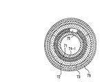
すなわち、図21に示す如く、いわば可動線輪型のスピーカと同様な原理に基づいて構成され、可動線輪(本願においては電磁コイルと呼ぶ)を支える共振バネ(後に説明する図23に示されている)と共振する交番電流を供給するようにした振動型圧縮機が公知となっている。なお、図21における71は電磁コイル、72はフェライト磁石、73は外部鉄心、74は内部鉄心、74−1は磁極、75は環状磁気間隙を表している。
【0004】
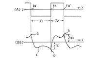
例えば、2個のスイッチング・トランジスタが交互にオンオフを繰り返すことによって生成される図22(A)図示の如き矩形波交流電圧が、図21に示された電磁コイル71に印加されて、当該電磁コイル71が図21図示の矢印aの状態とbの状態との間を上下に駆動される。但し、上記状態aは圧縮完了、状態bは吸入完了に対応する上記電磁コイル71を示している。そして、当該電磁コイル71の駆動電流iは2個の上記スイッチング・トランジスタのオンされたコレクタ電流(Ic)であって図22(B)に図示されている。
【0005】
この様な原理に基づき、機械的振動系(図23で説明する)を駆動する電磁コイル71に、当該機械的振動系の固有振動周期に同期する周波数の上記矩形波交流電圧を印加することにより、機械的振動系のピストンを効率良く駆動せしめ、当該ピストンの駆動で密閉容器内に流入された低圧の冷媒を圧縮し、高圧の冷媒として吐出することが可能な振動型圧縮機となる。
【0006】
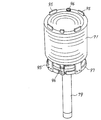
図23は従来の振動型圧縮機の断面図、図24は図23図示X−Xにおける断面図である。
【0007】
図23,図24において、符号71ないし75は図21に対応しており、76,77は共振バネ、78はコイル支持体、79はピストン、80は吸気弁、81は圧縮シリンダ、82は排気弁、83はシリンダ・ブロック、84はディスタンス・ケース、85はスクリュ、86は吸入口、86−1は内部吸入パイプ、87は吐出口、87−1,87−2は吐出パイプ、88はリード端子、88−1はリード線、89はハウジングをそれぞれ表している。
【0008】
フェライト磁石72は弧状に形成されて壺状の外部鉄心73の内周面に沿って配置されている。そして、上記フェライト磁石72は厚み方向、すなわち図24において放射方向に着磁されている。従って、外部鉄心73と共に磁気路を形成する内部鉄心74に、上記フェライト磁石72の内周面に対向するよう形成されている磁極74−1と上記フェライト磁石72との対向する空間に磁気空間、すなわち環状磁気間隙75が形成されている。
【0009】
当該環状磁気間隙75には、相対する一対の共振バネ76,77にコイル支持体78を介して振動可能に支持された電磁コイル71が配置されている。さらに、ピストン79は上記コイル支持体78を介して実質的に上記電磁コイル71と一体に構成されており、当該電磁コイル71によって駆動される。また、上記ピストン79に嵌合する圧縮シリンダ81を備えているシリンダ・ブロック83は、ディスタンス・ケース84を介してシリンダ固定用のスクリュ85によって外部鉄心73に固定されている。
【0010】
この様に構成された振動型圧縮機において、リード端子88、リード線88−1を介して上記電磁コイル71に交番電流が供給されると、当該電磁コイル71は供給される交番電流の周波数に対応して振動し上記ピストン79が駆動される。当該ピストン79の往復運動によって、吸入口86から流入する冷媒、例えばフレオン・ガスはハウジング89内を図示矢印(点線)方向に誘導され、更に内部吸入パイプ86−1内を通過して図示矢印(点線)に示す如く圧縮シリンダ81内に導入される。
【0011】
そして、上記ピストン79によって圧縮された高圧の冷媒は図示矢印(実線)方向に吐出され、吐出パイプ87−1,87−2、吐出口87を介して例えば、冷却システムの凝縮器に噴出される。なお、上記圧縮シリンダ81における冷媒の吸気・排気は、吸気弁80と排気弁82とが、上記ピストン79の往復運動に対応して交互に開閉することによって行われることは言うまでもない。
【0012】
ところで、上記電磁コイル71の巻線は、従来次の様にして製造されていた。図23に図示された電磁コイル71の巻線構成を改良した従来の電磁コイル71の巻線構成を示す図25を参照しながら説明すると、所定の径を有する巻き治具に電磁コイル71の一部を内側用として巻き、当該内側用の電磁コイル71の一部を巻き終えた時点で巻線作業を停止させ、この内側に巻かれた一部の電磁コイル71に、当該電磁コイル71で発生した力をピストン79に伝えるための4本のコイルヨークプレート95と2本のリードプレート96とを手作業で位置決めした上で、再び外側用として電磁コイル71の残りの巻線作業を行い、4本のコイルヨークプレート95と2本のリードプレート96とを中にしたサンドイッチ構造で所定の巻き数の電磁コイル71を巻き、2本のリードプレート96に電磁コイル71の巻き始め端と巻き終わり端をそれぞれ巻付け、電気的接続をしていた。
【0013】
その後、巻き治具から当該電磁コイル71を外した後ワニス処理で固形化し、電磁コイル71のコイルヨークプレート95の各片端にピストン79の一端を溶接したフランジ部97をスポット溶接し、ピストン79と電磁コイル71とを実質上一体化するようにしていた。
【0014】
上記図23で説明の外部鉄心73とシリンダ・ブロック83との従来の固定方法は、
〔1〕 外部鉄心73全体の径を増やしてねじ止めする
〔2〕 図23図示の如く、外部鉄心73の下端部に膨らみを持たせ、つまり外部鉄心73の一部分の径を増やしてねじ止めする
〔3〕 図27(当該図27は図23のものに改良を加えたもので、基本的には同様の機能を備えている)や図28図示の如く、外部鉄心73内にねじ取付け幅を確保する別ピースを挿入し、ねじ止めする
のねじ止めが用いられていた。
【0015】
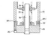
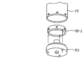
なお、図27,図28において、図23と同じものは同じ符号が付されており、図27では外部鉄心73の内部にねじ孔の切られた環状ピース98−1をねじ99で固定してねじ取付け幅を確保しておき、当該環状ピース98−1に切られたねじ孔にスクリュ85でシリンダ・ブロック83を固定する構造のものであり、図28では外部鉄心73とシリンダ・ブロック83との間にねじ取付け幅を確保する固定用ピース98−2を介して外部鉄心73とシリンダ・ブロック83とをねじで固定する構造のものである。
【0016】
【発明が解決しようとする課題】
従来の振動型圧縮機に用いられている永久磁石72(図23のフェライト磁石72に該当)はフェライト系磁石に代表される高保持力磁石が用いられていると共に、当該永久磁石72は外部鉄心73の内周面に固着されており、当該永久磁石72と内部鉄心74との間の環状磁気間隙75に電磁コイル71を配置する構造を採用しているため、振動型圧縮機の小型化が阻害されていた。
【0017】
この振動型圧縮機の小型化と共に、更にその高効率化が求められており、フェライト系磁石より高性能のネオジム磁石若しくは希土類磁石を用いるに当たっても、本願の振動型圧縮機では永久磁石72は、電磁コイル71が配置される場所での空隙、すなわち上記環状磁気間隙75において、その円周全体に放射方向(半径方向)に着磁する必要がある。
【0018】
ここでの永久磁石72の最も好ましい形状は、円筒形(環状も含まれる)であるが、ここで使用するネオジム磁石若しくは希土類磁石は高性能であり、高残留磁束密度Brであるため、磁石を製造するに当たって次のような難点がある。
【0019】
(1) 全体の結晶粒の配向性を放射方向にするための磁界をかけながら成形する際、磁石内径の断面積が小さいため結晶粒の配向を十分にできず、磁石材料の持っている本来の特性より落ちるものとなる。
【0020】
(2) 放射方向の磁界をかけるため、成形は1ケ取りしかできない。
【0021】
(3) 成形焼結後、寸法を出すための研磨をするが、この形状、すなわち円筒形では内径側研磨での寸法が出難く、コスト高となる。
【0022】
一方、従来の振動型圧縮機に用いられている外部鉄心73とシリンダ・ブロック83とのねじ止めを用いた従来の固定方法では、
(4) 外部鉄心本来の機能は磁束を通すことであるが、上記〔1〕,〔2〕の様に径を増やすと必要以上に外部鉄心73が太くなり、重量および直材費がアップする。
【0023】
(5) 外部鉄心73とシリンダ・ブロック83とに孔やねじ孔を開けることにより加工費がアップする。
【0024】
(6) 上記〔3〕の様に外部鉄心73の径を最適にしても、別ピースを用いる分その加工費および直材費がアップする。
【0025】
(7) シリンダ・ブロック83を外部鉄心73にねじ止めする場合、3,4本のねじで均等に締め付けなければならない。それができていない場合、シリンダ・ブロック83と共振ばね76,77が偏当たりし、性能不良となる恐れがあり、組み付けに際しては十分に注意しなければならない。
【0026】
など、要するに、直材費と加工費とが高くなり、重量が増え、そして組み立て難くなる。
【0027】
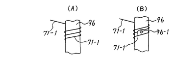
また図25に示された従来のリードプレート96は、ストレートな形状であるため、図26(A)図示の如く、リードプレート96に電磁コイル71の端末71−1を絡めてスポット溶接を行うと、図26(B)図示の如く溶接箇所96−1から電磁コイル71の端末71−1が逃げてしまい、溶接が困難であった。
【0028】
本発明は、上記の点に鑑みなされたものであり、永久磁石の選択に当たって、当該永久磁石のコストおよびその性能面から、磁気回路としての効率のよい磁石の最適の分割数に選択の上分割して使用すると共に、当該永久磁石を内部鉄心側に固着する構造にし、直材費と加工費とをアップすることなく、また、重量を重くすることなしに、そして大量生産に適した構成部品構造とすると共に、組み立てをも容易にした振動型圧縮機を提供することを目的としている。
【0029】
【課題を解決するための手段】
上記の目的を解決するために、本発明の振動型圧縮機は給電端子及び低圧の冷媒が流入する吸入管と圧縮された高圧の冷媒が流出する吐出管とを備えた密閉容器の内部に圧縮機本体が収納され、当該圧縮機本体は、円筒状のヨーク、当該ヨークの一端を閉塞すると共に内部に同軸状に突出した円柱状のコアポールで形成された磁路部材、その磁気路に配置された円筒状の永久磁石、当該磁路部材間の空隙内に機械的振動系に振動可能に支えられて配置されると共に、リードプレートに巻回されその端末が接続処理される構造の電磁コイル、電磁コイルを支持する支持部材、支持部材を介して電磁コイルに連結されたピストン、及び上記円筒状のヨークの他端を閉塞すると共に内部に吸入管に連通した低圧室と吐出管に連通した高圧室と上記ピストンを収納するシリンダ部とが形成されたシリンダ・ブロックを備え、上記電磁コイルに交番電流を供給することによって上記電磁コイルに連結されたピストンを振動させ、圧縮された高圧の冷媒を吐出管から排出する構造の振動型圧縮機において、上記円筒状の永久磁石はネオジム磁石若しくは希土類磁石でなり、かつ、上記円筒状の永久磁石はその軸方向に4分割もしくは5分割され、この分割された磁石は上記円柱状のコアポール側に接着固定されてなることを特徴としている。
【0030】
そして上記永久磁石がその軸方向に4分割された場合には、その4分割された磁石は、当該4分割された各磁石の弧状両端の軸中心に対する内径角度が88°以上89.8°以下に形成され、各磁石の弧状両端が各間隙を持って上記円柱状のコアポール側に接着固定されていることを特徴としている。
【0031】
また、上記コアポールは、4分割もしくは5分割された磁石が接着される磁石装着溝が形成されると共に、当該磁石がコアポールの所定位置に寸法通り貼り付けられるべく、磁石装着溝の端部に当該磁石装着溝の外径より小さい径の位置決め用の逃げ溝が設けられ、かつコアポールが円筒状のヨークと嵌合する当該コアポールの嵌合部の円周部分に小リブが設けられていることを特徴としている。
【0032】
また,上記円筒状の永久磁石はネオジム磁石若しくは希土類磁石でなり、かつ、上記円筒状の永久磁石はその軸方向に4分割もしくは5分割され、この分割された各磁石の表面はメッキレスで上記円柱状のコアポール側に接着固定されてなることを特徴としている。
【0033】
永久磁石をコアポール側に固着する構造を用い、永久磁石をコストとその磁気特性との関係から、永久磁石を4分割もしくは5分割する構造としたので、残留磁束密度Brの高いネオジム磁石若しくは希土類磁石を効果的に用いることができ、振動型圧縮機の効率を向上させることができる。
【0034】
上記永久磁石がその軸方向に4分割された場合には、その4分割された磁石は、当該4分割された各磁石の弧状両端の軸中心に対する内径角度が88°以上89.8°以下で形成され、各磁石の弧状両端が各間隙を持って上記円柱状のコアポール側に接着固定されているので,各磁石が割れることはない。
【0035】
【発明の実施の形態】
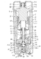
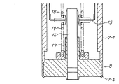
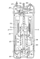
図1は本発明に係る振動型圧縮機の一実施例断面図を示している。
【0036】
同図において、振動型圧縮機1は、円筒2−1および当該円筒2−1の両開口端を閉塞する蓋2−2,2−3により構成される円筒状の密閉容器2内に圧縮機本体3がバネ4,5などにより弾性的に支持されて構成されている。
【0037】
圧縮機本体3のケーシング6は、磁路部材7すなわち、外部鉄心たる円筒状のヨーク7−1、ヨーク7−1の一端、すなわち上端を閉塞すると共に内部に同軸状の円柱体が突出したフランジ付の内部鉄心たるコアポール7−2の集合体、および上記磁路部材7の他端、すなわち下端にシリンダ・ブロック8を固定して構成されている。
【0038】
上記コアポール7−2の上部は、上記ヨーク7−1の内周面に対して垂直に交差する段差部7−3と、当該ヨーク7−1の内周面に嵌合する嵌合部7−4とが形成されている。そして図1に示されている様に、上記嵌合部7−4を上記ヨーク7−1の内周面に嵌合せしめるようにして、上記コアポール7−2とヨーク7−1とをねじ止めや溶接で固定することによって、上記磁路部材7が構成される。
【0039】
また、上記シリンダ・ブロック8は、基本的に厚肉の円盤状に形成されており、磁路部材7の下端に嵌合されている。そして、上記磁路部材7の下端、すなわちヨーク7−1の先端部分にカシメ部7−5が形成されており、当該カシメ部7−5でヨーク7−1の内径部に嵌め込まれたシリンダ・ブロック8の下端面の全周又は複数箇所がカシメられ、シリンダ・ブロック8が磁路部材7の下端に固定される構造が用いられている。
【0040】
コアポール7−2の一端は段付小径部となって磁石装着溝11が形成されており、この環状側部外面、すなわち磁石装着溝11の外周面に沿って永久磁石12が固着されている。当該円筒状の永久磁石12と上記円筒状のヨーク7−1との間には、環状磁気間隙13が形成されている。上記永久磁石12にはネオジム磁石若しくは希土類磁石が用いられており、その磁気特性と振動型圧縮機1の外径寸法を小さくするために弧状に形成され、厚み方向すなわち放射方向(半径方向)に着磁される。
【0041】
当該ネオジム磁石若しくは希土類磁石は高性能磁石であり、高残留磁束密度Brであるため、電磁コイル14が配置される場所での空隙、すなわち環状磁気間隙13の高効率化がはかられ、振動型圧縮機1の高効率が得られる。そして当該永久磁石12は、後に詳しく説明する様に、4分割された形状のものが用いられている。
【0042】
上記環状磁気間隙13には、電磁コイル14がケーシング6の軸線方向、すなわち上下方向に往復自在に配置されている。この電磁コイル14は支持部材15に巻回されており、当該支持部材15はケーシング6の軸線と同心の円筒状ピストン16に固着されている。
【0043】
従って、電磁コイル14とピストン16とは実質的に一体化されている。このピストン16は、ケーシング6内に突入するようにして、シリンダ・ブロック8に一体的に設けられたシリンダ部17に摺合されている。またコアポール7−2と支持部材15との間には図1に示された如く、共振バネ18が介装され、支持部材15とシリンダ・ブロック8との間にも共振バネ19が介装されている。従って、ピストン16は上下一対の共振ばね18,19によって支持されることになる。更に、ピストン16の下端には吸入弁20が装備されている。
【0044】
シリンダ・ブロック8の下部には、図示省略したスクリュによって帽状蓋21が固着されている。この帽状蓋21とシリンダ・ブロック8との間には、シリンダ部17内でピストン16の下方に位置するシリンダ室22の更に下方に吐出弁室23が設けられると共に、シリンダ・ブロック8に設けられた孔を帽状蓋21で塞ぐことにより高圧室24および低圧室25が形成されている。
【0045】
帽状蓋21には、吐出弁室23と高圧室24との間を連通する連通路26が穿設されている。また、上記高圧室24に連通する吐出管27が設けられ、当該吐出管27は蓋2−3を貫通して外部に引き出され、例えば図示省略した冷蔵庫のコンデンサに接続される。つまり、圧縮機本体3で圧縮された高圧冷媒が当該コンデンサに吐出される。当該圧縮された高圧冷媒はコンデンサその他の機器を経て低圧冷媒となる。この低圧冷媒は、上記蓋2−3を貫通して設けられている吸入管28、帽状蓋21を貫通して低圧室25に連通するチューブ28−1、および低圧室25とケーシング6の内部とを連通するチューブ28−2を介してケーシング6、すなわち圧縮機本体3の内部に導入される。
【0046】
吐出弁室23には、シリンダ室22の下端においてシリンダ・ブロック8に設けられた弁座29に着座し得る吐出弁30と、吐出弁30を弁座29に着座する方向に付勢する抑圧バネ31とが収納されている。
【0047】
また、蓋2−3には給電端子32が取り付けられ、当該給電端子32はケーシング6内に導入され、図1では明示されていないが、電磁コイル14の一端に接続されている。電磁コイル14の他端は図示省略のリード線等によって密閉容器2に接続されている。従って、上記給電端子32と密閉容器2との間に交番電圧を印加することによって、上記電磁コイル14に交番電流を供給することが可能となっている。
【0048】
更に、コアポール7−2及び帽状蓋21には、突起部7−6および21−1に対応する位置に、例えばゴム等の弾性体によってリング状に形成された緩衝部材33および34が設けられている。従って圧縮機本体3の非所望な揺動を当該緩衝部材33,34によって最小限度の範囲に抑制できるようになっている。
【0049】
いま、電磁コイル14に交番電流が流れると、当該交番電流の極性に応じて、ピストン16が上記電磁コイル14と共に上下に振動し、ピストン16の上下振動は一対の共振バネ18,19によって増幅される。増幅された当該ピストン16の上下振動により、吸入弁20および吐出弁30がポンプ作用を行い、当該ポンプ作用により密閉容器2内に導入された冷媒などの流体は、吸入管28,チューブ28−1、低圧室25、チューブ28−2を介してケーシング6の内部に流入し、ピストン16、吸入弁20、シリンダ室22および吐出弁30を経て吐出弁室23に流入し、更に連通路26、高圧室24および吐出管27を介して冷蔵庫のコンデンサなどに吐出される。
【0050】
ところで、図1のものと従来の図23のものとでは、図2ないし図6で説明するコアポール7−2の形状や当該コアポール7−2の外周面に設けられた磁石装着溝11に固着されている永久磁石12(図1では図23との相違が表れていない)、図10で説明するヨーク7−1とシリンダ・ブロック8との固定方法、図11ないし図15で説明する電磁コイル14の端末14−1をリードプレート36に電気的接続する当該リードプレート36の形状の部分(図1では図23との相違が表れていない)、そして図16ないし図20で説明する電磁コイル14を支持する支持部材15の構造が異なっている。
【0051】
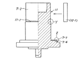
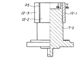
図1に示されている円筒状の永久磁石12は、その軸方向に4分割に分割されており、4分割された永久磁石12−1ないし12−4が図6に示されている如く、円筒状に復元された形態でコアポール7−2の外周面に設けられた磁石装着溝11にそれぞれ固着されている。
【0052】
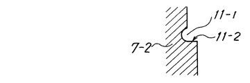
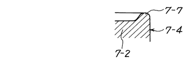
上記コアポール7−2には、図2に示されているように、4分割された永久磁石12−1などが接着される磁石装着溝11が形成されている。そして当該永久磁石12−1がコアポール7−2の所定位置に寸法通り貼り付けられるべく、磁石装着溝11の端部に当該磁石装着溝11の外径より少し小さい径で凹状の位置決め用の逃げ溝11−1が、図3図示の如く設けられており、またコアポール7−2の嵌合部7−4の円周部分は、図4図示の如く小リブ7−7が設けられている。
【0053】
上記4分割された永久磁石12−1ないし12−4はコアポール7−2の磁石装着溝11にそれぞれ固定されるが、この固定に当たって、図5図示のような上下方向の姿勢で、コアポール7−2と永久磁石12−1ないし12−4との間に接着剤を流し込み、或いはコアポール7−2の磁石装着溝11に接着剤を塗布した後に永久磁石12−1ないし12−4を貼り付け、加熱して硬化させ、永久磁石12−1ないし12−4をコアポール7−2に接着固定する。
【0054】
このとき接着剤全体が行き渡り、特に逃げ溝11−1に接着剤の量が部分的に多くなるため、永久磁石12−1ないし12−4の端面部の接着力を増大させる。接着剤の量は、部品の寸法バラツキを考慮して決定されるが、磁石装着溝11に流し込まれた接着剤或いは塗布された接着剤が、逃げ溝11−1から溢れて直ぐ下のコアポール7−2の外径面を伝わって下りてきても、上記コアポール7−2の嵌合部7−4の円周部分に設けられた小リブ7−7によって、嵌合部7−4にまで流れることが防止される。従って、接着剤量の厳格な管理が不要となる。
【0055】
振動型圧縮機1の性能をバラツキなく生産するには、当該永久磁石12−1ないし12−4をコアポール7−2の所定位置に寸法通り固定することが必要であるが、磁石装着溝11の外径より少し小さい凹状の位置決め用の逃げ溝11−1が設けられているので、永久磁石12−1ないし12−4の端面部がこの逃げ溝11−1の突き当て部11−2に完全に当接することにより、永久磁石12−1などのコアポール7−2の軸方向に対する接着位置のバラツキを無くすことができる。従って振動型圧縮機1の性能を100%発揮できる。
【0056】
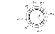
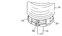
軸方向に4分割された永久磁石12−1ないし12−4は図5図示の如く、円筒状に復元された形態でコアポール7−2に設けられた磁石装着溝11にそれぞれ接着固定されるが、この4分割された永久磁石12−1ないし12−4は、当該4分割された各永久磁石12−1ないし12−4の弧状両端の軸中心に対する内径角度θが88°以上89.8°以下で形成され、各永久磁石12−1ないし12−4の弧状両端が各間隙35を持って円筒状に固定される。
【0057】
この各永久磁石12−1ないし12−4の弧状両端に間隙35を持たすのは、上述したように、永久磁石12−1ないし12−4をコアポール7−2の所定の位置に接着剤を用いて固定する際、加熱して硬化させ永久磁石12−1ないし12−4とコアポール7−2とを接着させる。つまり接着剤を硬化させるため、常温から硬化温度の、例えば150°C位まで一旦加熱し、その後常温まで冷却する。
【0058】
ネオジム磁石は一般の金属と異なり、その熱膨脹率は負の値を持つが故、磁性材のコアポール7−2の熱膨脹率と永久磁石12−1ないし12−4の熱膨脹率とは相反し、永久磁石12−1ないし12−4の相互間に、図6図示の如く間隙35を設けないと、上記常温から硬化温度や硬化温度から常温への温度変化によって、熱膨脹差が生じ当該永久磁石12−1ないし12−4に圧力がかかって割れが生じる。
【0059】
これを避けるため永久磁石12−1ないし12−4の相互間に間隙35を設けるのであるが、次のような問題が生じる。すなわち振動型圧縮機1では、ラジアル着磁、つまり円筒の内部と外部でN極S極となるので、一般的な回転形のモータの界磁のように、円筒の内部が N極S極のように繰り返さない特殊な構造のため、磁石を分割した場合には、反ぱつとともに、境界では起磁力の減衰が生じる。この起磁力の減衰、つまり性能の劣化をできるだけ小さくしつつ、磁石の割れを防止することが望ましい。
【0060】
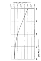
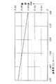
図7はネオジム磁石の内径角度とフラックスとの特性の一実施例測定曲線図、図8は温度差と膨脹差との特性の一実施例測定曲線図を示している。
【0061】
図7から磁石の内径角度が小さくなる程その磁性特性が悪くなること、そして図8の温度差が大きくなる程膨脹差が大きくなることに鑑み、ネオジム磁石を4分割するときには、図6で表された4分割された各永久磁石12−1ないし12−4の弧状両端の軸中心に対する内径角度が88°以上89.8°以下のとき、もっとも良好な結果が得られることを実験によって得た。
【0062】
このように永久磁石12−1ないし12−4の相互間に間隙35を設けることにより、永久磁石12−1ないし12−4の割れが生じなくなり、例えばエポキシ系やそれ以外の熱硬化性の接着剤の選択の範囲を拡大させることができる。
【0063】
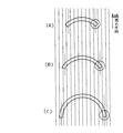
図9は永久磁石を4分割、3分割、2分割したときの特性比較説明図を示しており、図9(A)は4分割のもの、同図(B)は3分割のもの、同図(C)は2分割のものを示している。
【0064】
円筒状の永久磁石が分割され、分割された各分割永久磁石がコアポール7−2の外周面に固着されるときの、当該3分割、2分割の場合では、成形するとき磁界を図9図示の矢印の方向に平行にかけて着磁するため、端部での円で囲われた部分の結晶粒の配向が、放射方向でなくなってしまう。
【0065】
これに対し、その4分割の場合には、3分割、2分割のものに比べ、その端部での円で囲われた部分の結晶粒の配向は格段に良好となることが分かる。一方、分割数を増やした場合、磁石と磁石との合わせ目では反発しあい、磁力が無くなってしまう。またコアポール7−2への固着に当たって、その手間が増えることとなる。これらの磁気特性と手間とを総合的に考慮すると4分割が最良の選択と思慮され、5分割が次に続く選択となる。
【0066】
ここでの4分割された永久磁石12は、ネオジム磁石若しくは希土類磁石が用いられる。当該ネオジム磁石若しくは希土類磁石は高性能磁石であり、高残留磁束密度Brであるため、環状磁気間隙13に電磁コイル14が配置されるので永久磁石12の動作点としてBHmax近辺での設計が可能となり、電磁コイル14に流す交番電流が少なくても動作可能のため高効率化がはかられ、振動型圧縮機の高効率が得られる。
【0067】
なお、ネオジム磁石は、防錆のためメッキ等の表面処理がなされるが、振動型圧縮機1においては、当該ネオジム磁石の4分割された各永久磁石12−1ないし12−4が置かれる環境は密閉容器2内の酸素が無い環境であり、しかも冷媒(例えばHFC−134a)とこの冷媒にマッチした専用潤滑油のみであるから、防錆の意味でのメッキ処理はなされない。このメッキレスとしたことは、上記接着剤の選択範囲を広げると共に、コストダウンにも寄与する。
【0068】
図10は本発明に係るヨークとシリンダ・ブロックとの一実施例固定説明図を示している。
【0069】
同図において、図1のものと同じものは同じ符号が付されている。本発明のヨーク7−1の先端部分、すなわち下端部の内側内径はシリンダ・ブロック8が嵌め込まれる形状に切削されると共に、当該ヨーク7−1の先端部分にカシメ部7−5が形成され、当該カシメ部7−5でヨーク7−1に嵌め込まれるシリンダ・ブロック8の端面がカシメられて固定される。このヨーク7−1の先端部分に形成されるカシメ部7−5は少なくとも複数個形成され、シリンダ・ブロック8を部分的にカシメ、或いは当該ヨーク7−1の先端部分全周にカシメ部7−5を形成し、シリンダ・ブロック8の全周がカシメられる構造とされている。
【0070】
このようにヨーク7−1の先端部分でシリンダ・ブロック8を部分的に或いは全周をカシメるようにしたので、別ピースを用いることなしに最適のヨーク7−1の径を設定できる。またねじを用いないので、ねじの締め付けやねじ切りの加工時間が不要であり、注意が必要だった組み付けも、カシメる方法でシリンダ・ブロック8を均等に容易に固定できる。
【0071】
また、永久磁石12、すなわち4分割された永久磁石12−1ないし12−4が磁石装着溝11を介してコアポール7−2側に設けられ、かつヨーク7−1の先端部分に形成されたカシメ部7−5でシリンダ・ブロック8をカシメる構造としたので、ケーシング6の外径を小さくでき、従って振動型圧縮機1の小型化がはかれる。
【0072】
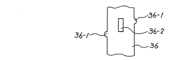
図11は本発明に係るリードプレートが用いられている電磁コイルの部分斜視図を示している。
【0073】
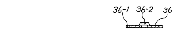
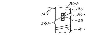
同図において、図1と同じものは同じ符号が付されている。リードプレート36の両端には、図12のリードプレートの一実施例部分拡大図に示されている様に、位置をずらして突起部36−1がそれぞれ設けられている。また当該リードプレート36の幅の中央位置で、かつ2つの突起部36−1の中間位置に、図13図示の如く凸部36−2が形成されている。なお、図11において、35はコイルヨークプレート、37はフランジ部である。
【0074】
リードプレート36が上述の様な形状を有するので、電磁コイル14の端末14−1を2つの突起部36−1を用いて、図14図示の如く絡ませると、電磁コイル14の端末14−1は、凸部36−2の位置を通過した形態でリードプレート36に絡ませられる。このとき2つの突起部36−1で電磁コイル14の端末14−1の逃げを防ぐことができ、凸部36−2の位置で溶接することにより、リードプレート36と電磁コイル14の端末14−1とが溶接箇所38(図14参照)で確実に溶接できる。
【0075】
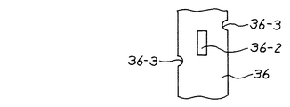
図15はリードプレートの他の実施例部分拡大図を示している。
【0076】
図15の場合は図12の突起部36−1に替え、切欠き36−3が形成された形状のものである。当該2つの切欠き36−3によって図12の突起部36−1の場合と同様の働きをなすことができる。
【0077】
図16ないし図18はピストンとコイルとの支持部材の部分の従来の構成を説明する図である。
【0078】
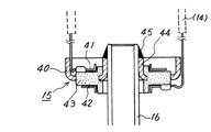
図中の符号15は支持部材、16はピストン、40はフランジ、41,42は夫々ターミナル(電磁コイルの)、43は絶縁体であって樹脂モールドで形成されるもの、44はカラー、45は溶接部を夫々表している。
【0079】
従来の場合、図16に示す如く、フランジ40は,絶縁体43を支える役割をはたすもので、図17に示す如く、フランジ40とカラー44とは金属体で構成される皿状体の一体物であり、当該皿状体の底面に存在する孔を介して絶縁体43(樹脂)が当該皿状体と機械的に固定されるように一体にモールドされて形成される。そして、図17に示す絶縁体43の水平状の面の上面と下面とに、電磁コイルに通電するためのターミナル41,42が例えばネジ止めされる。
【0080】
図17に示すようにモールドされた状態で、カラー44が図16に示すようにピストン16と溶接部45において溶接される。また上述のように電磁コイルがターミナル41,42と電気的に接続される。即ち,ピストン16は電磁コイル全体をピストンの動きと共に一緒に上下動させる。
【0081】
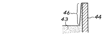
従来の場合、図16と図17とを用いて説明したように構成されているが、次の問題が生じていた。即ち、図18に示す如く、環状のカラー44の内法(うちのり)側に、絶縁体43をモールドした際のバリ46が非所望に形成されることが多い。このために、当該バリ46を手作業で削り取ることが行なわれて、煩雑であった。
【0082】
さらに言えば,フランジ(とカラー)の製作工程とモールド工程は、製造機械が全く異なるため、時間的に流通経路が長く、フランジ(とカラー)に錆が発生しやすい。このため、フランジ(とカラー)加工は金属部分を加工してから防錆油を塗布しておく。そして、樹脂モールド工程では、前処理として、防錆油を洗浄し、その後モールドする。この際に上述の如く樹脂モールド時に、フランジ(とカラー)の板厚のバラツキから樹脂ダレが生じることがあるため、ダレによるバリ取りの工程が不可欠となる。これは生産工程の増加とコストアップにつながる。
【0083】
また、カラーとピストンを溶接する際には、樹脂部分が焼ける虞もある。このためにモールドを行なわずかつ、錆が発生しづらく、バリ除去工程も不要となる手法を講じることが望まれる。また,工程順序の変更で樹脂の焼けも無いようにすることが望まれる。次に説明する支持部材はこれらの短所を改善した構造のものである。
【0084】
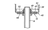
図19は本発明に用いられる電磁コイルの支持部材の他の実施例取付け説明図、図20は支持部材の分解説明図を示している。
【0085】
図19,図20において、支持部材15は、フランジ40と、互いに同一形状を有する絶縁材でなる2つのベース材47,48とで構成されている。フランジ40はその中心部にピストン16が嵌入される孔を有する内径ボス部49と、電磁コイル14を支持する電磁コイル支持筒50に嵌入される外径リブ部51とを備え、この内径ボス部49と外径リブ部51とで形成される円板部52に、上記2つのベース材47,48で円板部52を挟持固定するための孔53が複数個穿設されている。
【0086】
同一形状を有する2つのベース材47,48は、円板状の絶縁材で形成されており、その中心部にフランジ40に設けられた内径ボス部49が嵌入される径を有する内径リブ部54と、この内径リブ部54が形成された反対側の面に、フランジ40の円板部52に穿設された孔53に対応した位置に係止用凸部が設けられた係合部材55と、当該係合部材55の係止用凸部と係合する係止用凹部が設けられた係合部材56と、当該係合部材55,56が設けられた面の端縁部に少なくとも1つの平らな面を有する突起部57とがそれぞれ形成されている。
【0087】
図19に示された様にピストン16に支持部材15を組立てるには、ピストン16の所定位置にフランジ40を溶接して取付け、同一形状の2つのベース材47,48を図20図示の如く向け、ベース材47,48にそれぞれ設けられている係合部材55,56をフランジ40に穿設されている孔53に通し、相互に押圧してフランジ40の円板部52を2つのベース材47,48でサンドイッチ状にして固定する。
【0088】
この様に図19,図20で示される構成の支持部材15では、モールド成形を行わないため、錆が発生しづらく,バリ除去工程も不要となる。また工程順序の変更、すなわち最初にフランジ40をピストン16に溶接して固定するので、ベース材47,48の樹脂の焼けが発生することがない。
【0089】
以上の説明から明らかな様に大量生産に適した支持部材となっていることが理解されよう。
【0090】
なお、図19図20では図示されていないが、2つのベース材47,48には電磁コイル14からのリード線が接続されるターミナルが設けられるようになっている。
【0091】
【発明の効果】
以上説明した如く、本発明によれば、ネオジム磁石もしくは希土類磁石から構成した永久磁石を円柱状コアポール側に配置したので、電磁コイルが配置される磁気間隙の高磁束密度化によって電磁コイルに流れる交番電流が少なくなり効率の高い振動型圧縮機を提供することができる。そして永久磁石をコストとその磁気特性との関係から軸方向に4分割もしくは5分割したので,残留磁束密度Brの高いネオジム磁石若しくは希土類磁石を効果的に用いることができ、振動型圧縮機の効率を向上させることができる。そして,4分割もしくは5分割された永久磁石間に間隙も設けているので温度変化によっても永久磁石が割れることがない。
【図面の簡単な説明】
【図1】 本発明に係る振動型圧縮機の一実施例断面図である。
【図2】 コアーポールの一実施例部分断面図である。
【図3】 図2のY部分拡大図である。
【図4】 図2のZ部分拡大図である。
【図5】 4分割された永久磁石が固定されたコアーポールの一実施例部分断面図である。
【図6】 4分割された永久磁石の位置での横断面図である。
【図7】 ネオジム磁石の内径角度とフラックスとの特性の一実施例測定曲線図である。
【図8】 温度差と膨脹差との特性の一実施例測定曲線図である。
【図9】 永久磁石を4分割、3分割、2分割したときの特性比較説明図である。
【図10】 本発明に係るヨークとシリンダ・ブロックとの一実施例固定説明図である。
【図11】 本発明に係るリードプレートが用いられている電磁コイルの部分斜視図である。
【図12】 リードプレートの一実施例部分拡大図である。
【図13】 図12の正面図である。
【図14】 リードプレート部分での電磁コイルの端末の接続処理説明図である。
【図15】 リードプレートの他の実施例部分拡大図である。
【図16】 ピストンとコイルとの支持部材の部分の従来の構成を説明する図である。
【図17】 ピストンとコイルとの支持部材の部分の従来の構成を説明する図である。
【図18】 ピストンとコイルとの支持部材の部分の従来の構成を説明する図である。
【図19】 本発明に用いられる電磁コイルの支持部材の他の実施例取付け説明図である。
【図20】 支持部材の分解説明図である。
【図21】 従来の振動型圧縮機の原理を説明する部分断面図である。
【図22】 振動型圧縮機に供給される電圧波形及び電流波形図である。
【図23】 従来の振動型圧縮機の断面図である。
【図24】 図23図示X−Xにおける断面図である。
【図25】 従来のピストンが連結された電磁コイルの斜視図である。
【図26】 従来のリードプレート部分での電磁コイルの端末の接続処理説明図である。
【図27】 従来の内部鉄心とシリンダ・ブロックとの固定説明図である。
【図28】 従来の内部鉄心とシリンダ・ブロックとの固定分解説明図である。
【符号の説明】
1 振動型圧縮機
2 密閉容器
3 圧縮機本体
7 磁路部材
7−1 ヨーク(外部鉄心)
7−2 コアポール(内部鉄心)
8 シリンダ・ブロック
12 永久磁石
12−1,12−2,12−3,12−4永久磁石
13 環状磁気間隙
14 電磁コイル
16 ピストン
18,19 共振バネ
24 高圧室
25 低圧室
27 吐出管
28 吸入管
32 給電端子[0001]
BACKGROUND OF THE INVENTION
The present invention is divided into a vibration type compressor, in particular, a bottomed cylindrical outer core built in a hermetically sealed container, an inner core (core pole) constituting a magnetic path together with the outer core, and an inner core of the magnetic path. A permanent magnet disposed in an annular form, an electromagnetic coil disposed in an annular gap formed by the permanent magnet and an external iron core, and supported by a mechanical vibration system so as to vibrate, a piston coupled to the electromagnetic coil, and A cylinder block that houses the piston is provided, an alternating current is supplied to the electromagnetic coil to vibrate the piston connected to the electromagnetic coil, a low-pressure refrigerant flows into the sealed container, and a compressed high-pressure refrigerant is discharged. The present invention relates to a vibration type compressor.
[0002]
[Prior art]
Conventionally, a vibration type compressor that discharges a compressed high-pressure refrigerant by flowing a low-pressure refrigerant into a hermetic container is already known from Japanese Patent Publication No. 63-8315 related to the applicant's proposal.
[0003]
That is, as shown in FIG. 21, a so-called resonance spring (which will be described later in FIG. 23) is configured based on the same principle as a movable wire ring type speaker and supports a movable wire ring (referred to as an electromagnetic coil in this application). There is known a vibration type compressor that supplies an alternating current that resonates. In FIG. 21, 71 is an electromagnetic coil, 72 is a ferrite magnet, 73 is an external iron core, 74 is an internal iron core, 74-1 is a magnetic pole, and 75 is an annular magnetic gap.
[0004]
For example, a rectangular wave AC voltage as shown in FIG. 22A generated by alternately turning on and off two switching transistors is applied to the
[0005]
Based on such a principle, by applying the rectangular AC voltage having a frequency synchronized with the natural vibration period of the mechanical vibration system to the
[0006]
FIG. 23 is a sectional view of a conventional vibration type compressor, and FIG. 24 is a sectional view taken along line XX in FIG.
[0007]
23 and 24,
[0008]
The
[0009]
In the annular
[0010]
In the vibration type compressor configured as described above, when an alternating current is supplied to the
[0011]
The high-pressure refrigerant compressed by the
[0012]
Incidentally, the winding of the
[0013]
Thereafter, the
[0014]
The conventional fixing method of the
[1] Increase the overall diameter of the
[2] As shown in FIG. 23, the lower end portion of the
[3] As shown in FIG. 27 (FIG. 27 is an improved version of FIG. 23 and basically has the same function) and FIG. Insert another piece to secure and screw
Screwing was used.
[0015]
27 and 28, the same components as those in FIG. 23 are denoted by the same reference numerals. In FIG. 27, an annular piece 98-1 having a threaded hole is fixed inside the
[0016]
[Problems to be solved by the invention]
A permanent magnet 72 (corresponding to the
[0017]
Along with the miniaturization of the vibration type compressor, higher efficiency is demanded. Even when using a neodymium magnet or a rare earth magnet having higher performance than a ferrite magnet, the
[0018]
The most preferable shape of the
[0019]
(1) When molding while applying a magnetic field to make the orientation of the entire crystal grains radial, the orientation of the crystal grains cannot be sufficiently achieved due to the small cross-sectional area of the inner diameter of the magnet. It will fall from the characteristics of.
[0020]
(2) Since a radial magnetic field is applied, only one piece can be formed.
[0021]
(3) After forming and sintering, polishing is performed to obtain dimensions. However, in this shape, that is, a cylindrical shape, it is difficult to obtain the dimensions in the inner diameter side polishing, and the cost increases.
[0022]
On the other hand, in the conventional fixing method using the screwing of the
(4) The original function of the external iron core is to pass magnetic flux, but if the diameter is increased as in [1] and [2] above, the
[0023]
(5) By forming holes and screw holes in the
[0024]
(6)the aboveEven if the diameter of the
[0025]
(7) When the
[0026]
In short, the cost of direct materials and processing increases, the weight increases, and the assembly becomes difficult.
[0027]
Since the
[0028]
The present invention has been made in view of the above points. In selecting a permanent magnet, from the viewpoint of the cost and performance of the permanent magnet, it is selected and divided into an optimal number of divided magnets that are efficient as a magnetic circuit. In addition, the permanent magnet is fixed to the inner iron core, and the components are suitable for mass production without increasing the cost of direct materials and processing, and without increasing the weight. An object of the present invention is to provide a vibration type compressor having a structure and easy assembly.
[0029]
[Means for Solving the Problems]
In order to solve the above-mentioned object, the vibration type compressor of the present invention compresses the inside of an airtight container having a power supply terminal and a suction pipe into which a low-pressure refrigerant flows and a discharge pipe from which a compressed high-pressure refrigerant flows out. The compressor main body is housed, and the compressor main body is disposed on a magnetic path member formed of a cylindrical yoke, a cylindrical core pole that closes one end of the yoke and protrudes coaxially inside, and the magnetic path. A cylindrical permanent magnet, an electromagnetic coil having a structure in which the terminal is connected to the end of the lead plate by being wound and supported by a mechanical vibration system in a gap between the magnetic path members, A supporting member for supporting the electromagnetic coil, a piston connected to the electromagnetic coil via the supporting member, and a high pressure that closes the other end of the cylindrical yoke and communicates with the suction pipe and the discharge pipe inside. Room and above A cylinder block formed with a cylinder portion for storing the ton, and by supplying an alternating current to the electromagnetic coil, the piston connected to the electromagnetic coil is vibrated, and the compressed high-pressure refrigerant is discharged from the discharge pipe. In the vibratory compressor having a discharge structure, the cylindrical permanent magnet is a neodymium magnet or a rare earth magnet, and the cylindrical permanent magnet is disposed in the axial direction thereof.4 or 5 divisionsThe divided magnets are bonded and fixed to the cylindrical core pole side.
[0030]
And aboveWhen the permanent magnet is divided into four in its axial direction,The four-divided magnets are formed such that the inner diameter angle of each of the four-divided magnets with respect to the axial center of each arc-shaped end is 88 ° or more and 89.8 ° or less, and each arc-shaped end of each magnet has a gap between the circles. It is characterized by being bonded and fixed to the columnar core pole side.
[0031]
The core pole is divided into four parts.Or 5 divisionsA magnet mounting groove to which the magnet is bonded is formed, and the magnet is positioned at the end of the magnet mounting groove with a diameter smaller than the outer diameter of the magnet mounting groove so that the magnet can be attached to a predetermined position of the core pole. And a small rib is provided in the circumferential portion of the fitting portion of the core pole where the core pole is fitted with a cylindrical yoke..
[0032]
MaThe cylindrical permanent magnet is a neodymium magnet or a rare earth magnet, and the cylindrical permanent magnet is in the axial direction thereof.4 or 5 divisionsThe surface of each divided magnet is bonded and fixed to the cylindrical core pole side without plating..
[0033]
Using a structure in which the permanent magnet is fixed to the core pole side, the permanent magnet is fixed based on the relationship between cost and magnetic properties.4 or 5 divisionsThus, a neodymium magnet or a rare earth magnet having a high residual magnetic flux density Br can be used effectively, and the efficiency of the vibration type compressor can be improved.
[0034]
When the permanent magnet is divided into four in the axial direction,The four-divided magnets are formed so that the inner diameter angle with respect to the axial center of each arc-shaped end of each of the four-divided magnets is 88 ° or more and 89.8 ° or less, and the arc-shaped ends of each magnet have the respective gaps and the columnar shape. Since the core pole is bonded and fixed, each magnet does not break.
[0035]
DETAILED DESCRIPTION OF THE INVENTION
FIG. 1 shows a cross-sectional view of an embodiment of a vibration type compressor according to the present invention.
[0036]
In the figure, a vibration type compressor 1 includes a cylinder 2-1 and a cylindrical sealed
[0037]
The
[0038]
The upper portion of the core pole 7-2 includes a stepped portion 7-3 that intersects perpendicularly to the inner peripheral surface of the yoke 7-1 and a fitting portion 7- that fits to the inner peripheral surface of the yoke 7-1. 4 are formed. As shown in FIG. 1, the core pole 7-2 and the yoke 7-1 are screwed so that the fitting portion 7-4 is fitted to the inner peripheral surface of the yoke 7-1. The
[0039]
The
[0040]
One end of the core pole 7-2 has a stepped small diameter portion to form a
[0041]
Since the neodymium magnet or rare earth magnet is a high-performance magnet and has a high residual magnetic flux density Br, it is possible to improve the efficiency of the air gap at the place where the
[0042]
An
[0043]
Therefore, the
[0044]
A cap-shaped
[0045]
The cap-shaped
[0046]
The
[0047]
Further, a
[0048]
Further, the core pole 7-2 and the cap-shaped
[0049]
Now, when an alternating current flows through the
[0050]
By the way, the thing of FIG. 1 and the conventional thing of FIG. 23 are fixed to the magnet installation groove |
[0051]
The cylindrical
[0052]
As shown in FIG. 2, the core pole 7-2 is provided with a
[0053]
The four divided permanent magnets 12-1 to 12-4 are respectively fixed to the
[0054]
At this time, the entire adhesive spreads, and in particular, the amount of the adhesive partially increases in the escape groove 11-1, so that the adhesive force of the end face portions of the permanent magnets 12-1 to 12-4 is increased. The amount of the adhesive is determined in consideration of the dimensional variation of the parts. The
[0055]
In order to produce the performance of the vibration type compressor 1 without variation, it is necessary to fix the permanent magnets 12-1 to 12-4 to predetermined positions of the core pole 7-2 according to the dimensions. Since the concave positioning relief groove 11-1 that is slightly smaller than the outer diameter is provided, the end faces of the permanent magnets 12-1 to 12-4 are completely in the abutting portion 11-2 of the relief groove 11-1. , The variation in the bonding position of the core pole 7-2 such as the permanent magnet 12-1 with respect to the axial direction can be eliminated. Therefore, the performance of the vibration type compressor 1 can be exhibited 100%.
[0056]
As shown in FIG. 5, the permanent magnets 12-1 to 12-4 divided into four in the axial direction are bonded and fixed to the
[0057]
The
[0058]
Since neodymium magnets have a negative thermal expansion coefficient unlike ordinary metals, the thermal expansion coefficient of the core pole 7-2 of the magnetic material and the thermal expansion coefficient of the permanent magnets 12-1 to 12-4 are contradictory and permanent. If the
[0059]
In order to avoid this, the
[0060]
FIG. 7 shows an example measurement curve of the characteristics of the inner diameter angle of the neodymium magnet and the flux, and FIG. 8 shows an example measurement curve of the characteristics of the temperature difference and the expansion difference.
[0061]
In view of the fact that the smaller the inner diameter angle of the magnet, the worse the magnetic properties, and the larger the temperature difference in FIG. 8, the larger the difference in expansion. FIG. Experiments have shown that the best results can be obtained when the inner diameter angle of each of the four divided permanent magnets 12-1 to 12-4 with respect to the axial center of the arc-shaped ends is 88 ° or more and 89.8 ° or less. .
[0062]
Thus, by providing the
[0063]
FIG. 9 shows characteristic comparison diagrams when the permanent magnet is divided into four, three, and two parts. FIG. 9 (A) shows a four-part split, FIG. 9 (B) shows a three-part split, (C) shows the one divided into two.
[0064]
When the cylindrical permanent magnet is divided and each divided permanent magnet is fixed to the outer peripheral surface of the core pole 7-2, in the case of the three divisions and two divisions, the magnetic field is shown in FIG. Since magnetization is performed parallel to the direction of the arrow, the orientation of the crystal grains in the portion surrounded by the circle at the end is not in the radial direction.
[0065]
On the other hand, in the case of the 4-division, it can be seen that the orientation of the crystal grains in the portion surrounded by a circle at the end is markedly better than that in the case of 3-division and 2-division. On the other hand, when the number of divisions is increased, repulsion occurs at the joint between the magnets and the magnetic force is lost. In addition, the trouble is increased in fixing to the core pole 7-2. Taking these magnetic characteristics and labor into consideration, 4 division is considered the best choice, and 5 division is the next choice.
[0066]
The
[0067]
The neodymium magnet is subjected to surface treatment such as plating for rust prevention, but in the vibration type compressor 1, an environment in which each of the permanent magnets 12-1 to 12-4 divided into four parts of the neodymium magnet is placed. Is an environment in which there is no oxygen in the
[0068]
FIG. 10 shows a fixed explanatory view of an embodiment of a yoke and a cylinder block according to the present invention.
[0069]
In the figure, the same components as those in FIG. The front end portion of the yoke 7-1 of the present invention, that is, the inner inner diameter of the lower end portion is cut into a shape into which the
[0070]
Since the
[0071]
Further, the
[0072]
FIG. 11 shows a partial perspective view of an electromagnetic coil in which the lead plate according to the present invention is used.
[0073]
In the figure, the same components as those in FIG. At both ends of the
[0074]
Since the
[0075]
FIG. 15 shows a partially enlarged view of another embodiment of the lead plate.
[0076]
In the case of FIG. 15, it replaces the projection part 36-1 of FIG. 12, and is the shape in which the notch 36-3 was formed. The two notches 36-3 can perform the same function as that of the protrusion 36-1 in FIG.
[0077]
FIGS. 16 to 18 are views for explaining a conventional configuration of a support member portion of a piston and a coil.
[0078]
[0079]
In the conventional case, as shown in FIG. 16, the
[0080]
17, the
[0081]
In the conventional case, the configuration is as described with reference to FIGS. 16 and 17, but the following problem has occurred. That is, as shown in FIG. 18, the
[0082]
Furthermore, since the manufacturing process of the flange (and collar) is completely different from that of the molding process, the distribution path is long in time, and the flange (and collar) tends to rust. For this reason, in the flange (and collar) processing, the rust preventive oil is applied after the metal portion is processed. In the resin molding step, as a pretreatment, the rust preventive oil is washed and then molded. At this time, as described above, during resin molding, resin sagging may occur due to variations in the thickness of the flange (and collar), and therefore a deburring process using sagging becomes indispensable. This leads to an increase in production process and cost.
[0083]
Further, when the collar and the piston are welded, the resin portion may be burned. For this reason, it is desired to adopt a technique that does not perform molding, does not easily generate rust, and does not require a burr removal step. It is also desirable to prevent the resin from burning by changing the process sequence. The support member described below has a structure in which these disadvantages are improved.
[0084]
FIG. 19 is a view for explaining another embodiment of the support member for the electromagnetic coil used in the present invention, and FIG. 20 is an exploded view for explaining the support member.
[0085]
19 and 20, the
[0086]
The two
[0087]
To assemble the
[0088]
In this manner, the
[0089]
It will be understood from the above description that the support member is suitable for mass production.
[0090]
Although not shown in FIG. 19 and FIG. 20, the two
[0091]
【The invention's effect】
As described above, according to the present invention, since the permanent magnet composed of a neodymium magnet or a rare earth magnet is disposed on the cylindrical core pole side, the alternating current flowing through the electromagnetic coil by increasing the magnetic flux density of the magnetic gap in which the electromagnetic coil is disposed. It is possible to provide a vibration type compressor that has low current and high efficiency. And whether permanent magnets are related to cost and their magnetic properties?4 or 5 in the axial directionTherefore, a neodymium magnet or a rare earth magnet having a high residual magnetic flux density Br can be used effectively, and the efficiency of the vibration type compressor can be improved. And 4
[Brief description of the drawings]
FIG. 1 is a cross-sectional view of an embodiment of a vibration type compressor according to the present invention.
FIG. 2 is a partial cross-sectional view of one embodiment of a core pole.
FIG. 3 is an enlarged view of a portion Y in FIG. 2;
4 is an enlarged view of a portion Z in FIG. 2. FIG.
FIG. 5 is a partial cross-sectional view of an embodiment of a core pole to which a permanent magnet divided into four is fixed.
FIG. 6 is a cross-sectional view at a position of a permanent magnet divided into four parts.
FIG. 7 is a measurement curve diagram of an example of the characteristics of the inner diameter angle and flux of a neodymium magnet.
FIG. 8 is a measurement curve diagram of an example of characteristics of temperature difference and expansion difference.
FIG. 9 is a characteristic comparison diagram when the permanent magnet is divided into four parts, three parts, and two parts.
FIG. 10 is an explanatory diagram for fixing one embodiment of a yoke and a cylinder block according to the present invention.
FIG. 11 is a partial perspective view of an electromagnetic coil in which the lead plate according to the present invention is used.
FIG. 12 is a partially enlarged view of an embodiment of a lead plate.
FIG. 13 is a front view of FIG.
FIG. 14 is an explanatory diagram of connection processing of the terminal of the electromagnetic coil at the lead plate portion.
FIG. 15 is a partially enlarged view of another embodiment of the lead plate.
FIG. 16 is a diagram illustrating a conventional configuration of a support member portion of a piston and a coil.
FIG. 17 is a diagram illustrating a conventional configuration of a support member portion of a piston and a coil.
FIG. 18 is a diagram illustrating a conventional configuration of a support member portion of a piston and a coil.
FIG. 19 is an explanatory view of attachment of another embodiment of a support member for an electromagnetic coil used in the present invention.
FIG. 20 is an exploded view of the support member.
FIG. 21 is a partial cross-sectional view illustrating the principle of a conventional vibration type compressor.
FIG. 22 is a voltage waveform diagram and a current waveform diagram supplied to the vibration type compressor.
FIG. 23 is a cross-sectional view of a conventional vibration type compressor.
24 is a cross-sectional view taken along XX in FIG.
FIG. 25 is a perspective view of an electromagnetic coil to which a conventional piston is connected.
FIG. 26 is an explanatory diagram of connection processing of a terminal of an electromagnetic coil in a conventional lead plate portion.
FIG. 27 is a view for explaining fixing between a conventional internal iron core and a cylinder block.
FIG. 28 is a fixed exploded explanatory view of a conventional internal iron core and a cylinder block.
[Explanation of symbols]
1 Vibrating compressor
2 Airtight container
3 Compressor body
7 Magnetic path members
7-1 York (external iron core)
7-2 Core pole (inner iron core)
8 Cylinder block
12 Permanent magnet
12-1, 12-2, 12-3, 12-4 permanent magnet
13 Annular magnetic gap
14 Electromagnetic coil
16 piston
18, 19 Resonant spring
24 High pressure chamber
25 Low pressure chamber
27 Discharge pipe
28 Suction pipe
32 Feeding terminal
Claims (4)
上記円筒状の永久磁石はネオジム磁石若しくは希土類磁石でなり、
かつ、上記円筒状の永久磁石はその軸方向に4分割もしくは5分割され、この分割された磁石は上記円柱状のコアポール側に接着固定されてなること
を特徴とする振動型圧縮機。The compressor main body is housed in a sealed container including a power supply terminal and a suction pipe into which low-pressure refrigerant flows and a discharge pipe from which compressed high-pressure refrigerant flows out. The compressor body includes a cylindrical yoke, A magnetic path member formed by a cylindrical core pole that closes one end of the yoke and protrudes coaxially inside, a cylindrical permanent magnet disposed in the magnetic path, and a machine in the gap between the magnetic path members The electromagnetic coil is configured to be supported by a vibration system so as to vibrate, and is wound around a lead plate and connected to the end thereof, a support member that supports the electromagnetic coil, and is connected to the electromagnetic coil through the support member. A cylinder formed with a closed piston, a low pressure chamber communicating with the suction pipe, a high pressure chamber communicating with the discharge pipe, and a cylinder portion for housing the piston; A lock, in the by supplying an alternating current to the electromagnetic coil to vibrate the piston connected to the electromagnetic coil, the vibrating compressor of the structure for discharging the compressed high-pressure refrigerant from the discharge pipe,
The cylindrical permanent magnet is a neodymium magnet or a rare earth magnet,
The vibration-type compressor is characterized in that the cylindrical permanent magnet is divided into four or five in the axial direction, and the divided magnets are bonded and fixed to the cylindrical core pole side.
上記円筒状の永久磁石はネオジム磁石若しくは希土類磁石でなり、
かつ、上記円筒状の永久磁石はその軸方向に4分割もしくは5分割され、この分割された各磁石の表面はメッキレスで上記円柱状のコアポール側に接着固定されてなること
を特徴とする振動型圧縮機。The compressor main body is housed in a sealed container including a power supply terminal and a suction pipe into which low-pressure refrigerant flows and a discharge pipe from which compressed high-pressure refrigerant flows out. The compressor body includes a cylindrical yoke, A magnetic path member formed by a cylindrical core pole that closes one end of the yoke and protrudes coaxially inside, a cylindrical permanent magnet disposed in the magnetic path, and a machine in the gap between the magnetic path members The electromagnetic coil is configured to be supported by a vibration system so as to vibrate, and is wound around a lead plate and connected to the end thereof, a support member that supports the electromagnetic coil, and is connected to the electromagnetic coil through the support member. A cylinder formed with a closed piston, a low pressure chamber communicating with the suction pipe, a high pressure chamber communicating with the discharge pipe, and a cylinder portion for housing the piston; A lock, in the by supplying an alternating current to the electromagnetic coil to vibrate the piston connected to the electromagnetic coil, the vibrating compressor of the structure for discharging the compressed high-pressure refrigerant from the discharge pipe,
The cylindrical permanent magnet is a neodymium magnet or a rare earth magnet,
The cylindrical permanent magnet is divided into four or five in the axial direction, and the surface of each of the divided magnets is bonded and fixed to the cylindrical core pole side without plating. Compressor.
Priority Applications (6)
| Application Number | Priority Date | Filing Date | Title |
|---|---|---|---|
| JP2000325224A JP4691237B2 (en) | 2000-10-25 | 2000-10-25 | Vibration type compressor |
| US10/415,030 US6994530B2 (en) | 2000-10-25 | 2001-10-23 | Vibrating type compressor |
| AU2001295996A AU2001295996B2 (en) | 2000-10-25 | 2001-10-23 | Vibrating compressor |
| PCT/JP2001/009274 WO2002035095A1 (en) | 2000-10-25 | 2001-10-23 | Vibrating compressor |
| EP01976811A EP1335132A4 (en) | 2000-10-25 | 2001-10-23 | VIBRANT COMPRESSOR |
| AU9599601A AU9599601A (en) | 2000-10-25 | 2001-10-23 | Vibrating compressor |
Applications Claiming Priority (1)
| Application Number | Priority Date | Filing Date | Title |
|---|---|---|---|
| JP2000325224A JP4691237B2 (en) | 2000-10-25 | 2000-10-25 | Vibration type compressor |
Publications (2)
| Publication Number | Publication Date |
|---|---|
| JP2002130123A JP2002130123A (en) | 2002-05-09 |
| JP4691237B2 true JP4691237B2 (en) | 2011-06-01 |
Family
ID=18802619
Family Applications (1)
| Application Number | Title | Priority Date | Filing Date |
|---|---|---|---|
| JP2000325224A Expired - Lifetime JP4691237B2 (en) | 2000-10-25 | 2000-10-25 | Vibration type compressor |
Country Status (5)
| Country | Link |
|---|---|
| US (1) | US6994530B2 (en) |
| EP (1) | EP1335132A4 (en) |
| JP (1) | JP4691237B2 (en) |
| AU (2) | AU2001295996B2 (en) |
| WO (1) | WO2002035095A1 (en) |
Families Citing this family (14)
| Publication number | Priority date | Publication date | Assignee | Title |
|---|---|---|---|---|
| KR101681588B1 (en) * | 2010-07-09 | 2016-12-01 | 엘지전자 주식회사 | Linear compressor |
| BRPI1103355A2 (en) * | 2011-07-04 | 2013-07-23 | Whirlpool Sa | adapter device for linear compressor, and compressor provided with said device |
| CN104251192B (en) | 2013-06-28 | 2016-10-05 | Lg电子株式会社 | Linearkompressor |
| CN104251191B (en) * | 2013-06-28 | 2017-05-03 | Lg电子株式会社 | Linear compressor |
| CN104251195A (en) | 2013-06-28 | 2014-12-31 | Lg电子株式会社 | Linear compressor |
| CN104251193A (en) | 2013-06-28 | 2014-12-31 | Lg电子株式会社 | Linear compressor |
| CN104251197B (en) | 2013-06-28 | 2017-04-12 | Lg电子株式会社 | Linear compressor |
| CN104251196B (en) | 2013-06-28 | 2016-10-05 | Lg电子株式会社 | Linearkompressor |
| US9322401B2 (en) * | 2014-02-10 | 2016-04-26 | General Electric Company | Linear compressor |
| CN116389867A (en) * | 2014-12-17 | 2023-07-04 | Lg伊诺特有限公司 | Lens driving module, camera module and optical device |
| US20180049537A1 (en) * | 2016-08-16 | 2018-02-22 | Joy Walton Walton Kawasaki | Carrying Bag |
| KR101891480B1 (en) * | 2017-10-12 | 2018-09-28 | 한국기초과학지원연구원 | Bobbin and Coil Assembly and Electromagnet Equipment including thereof |
| WO2023074145A1 (en) * | 2021-10-26 | 2023-05-04 | 日立Astemo株式会社 | Actuator device |
| CN116604697B (en) * | 2023-06-20 | 2024-05-03 | 江苏江扬建材机械有限公司 | Vibrating device for mandrel vibrating pipe making machine |
Family Cites Families (17)
| Publication number | Priority date | Publication date | Assignee | Title |
|---|---|---|---|---|
| NL6704284A (en) * | 1967-03-23 | 1968-09-24 | ||
| US3814550A (en) * | 1972-12-07 | 1974-06-04 | Gen Electric | Motor arrangement and lubrication system for oscillatory compressor |
| JPS5641470A (en) * | 1979-09-11 | 1981-04-18 | Sawafuji Electric Co Ltd | Vibration-type compressor |
| US4427906A (en) * | 1980-03-13 | 1984-01-24 | Sawafuji Electric Co., Ltd. | Vibrating compressor |
| JPS6338384Y2 (en) * | 1980-03-13 | 1988-10-11 | ||
| JPS56129780A (en) | 1980-03-13 | 1981-10-12 | Sawafuji Electric Co Ltd | Oscillatory type compressor |
| JPS56129080A (en) | 1980-03-14 | 1981-10-08 | Takiron Co Ltd | Evaporator |
| JPS61126385A (en) * | 1984-11-22 | 1986-06-13 | Sawafuji Electric Co Ltd | Vibration type compressor |
| JPS638315A (en) | 1986-06-28 | 1988-01-14 | Sansho Seiyaku Kk | Drug for external use |
| JP2596751B2 (en) * | 1987-07-06 | 1997-04-02 | いすゞ特装開発株式会社 | Foldable box-type carrier |
| JPH086685B2 (en) * | 1990-09-10 | 1996-01-29 | ダイキン工業株式会社 | Linear motor compressor for Stirling refrigerator |
| AU681825B2 (en) * | 1995-05-31 | 1997-09-04 | Sawafuji Electric Co., Ltd. | Vibrating compressor |
| JP2790102B2 (en) * | 1995-12-01 | 1998-08-27 | ダイキン工業株式会社 | Linear motor type compressor |
| JP3734889B2 (en) * | 1996-06-27 | 2006-01-11 | アイチエレック株式会社 | Brushless DC motor |
| JP3747107B2 (en) * | 1996-12-18 | 2006-02-22 | アイチエレック株式会社 | Electric motor |
| US6848892B1 (en) * | 1997-10-15 | 2005-02-01 | Matsushita Refrigeration Company | Oscillation-type compressor |
| JP2000205123A (en) * | 1999-01-08 | 2000-07-25 | Sawafuji Electric Co Ltd | Vibration compressor |
-
2000
- 2000-10-25 JP JP2000325224A patent/JP4691237B2/en not_active Expired - Lifetime
-
2001
- 2001-10-23 WO PCT/JP2001/009274 patent/WO2002035095A1/en not_active Ceased
- 2001-10-23 AU AU2001295996A patent/AU2001295996B2/en not_active Ceased
- 2001-10-23 EP EP01976811A patent/EP1335132A4/en not_active Withdrawn
- 2001-10-23 US US10/415,030 patent/US6994530B2/en not_active Expired - Lifetime
- 2001-10-23 AU AU9599601A patent/AU9599601A/en active Pending
Also Published As
| Publication number | Publication date |
|---|---|
| WO2002035095A1 (en) | 2002-05-02 |
| EP1335132A1 (en) | 2003-08-13 |
| US20040001768A1 (en) | 2004-01-01 |
| US6994530B2 (en) | 2006-02-07 |
| AU2001295996B2 (en) | 2005-06-02 |
| EP1335132A4 (en) | 2009-08-05 |
| AU9599601A (en) | 2002-05-06 |
| JP2002130123A (en) | 2002-05-09 |
Similar Documents
| Publication | Publication Date | Title |
|---|---|---|
| JP4691237B2 (en) | Vibration type compressor | |
| US7075199B2 (en) | Reciprocating motor and reciprocating compressor having the same | |
| US4632645A (en) | Vibrating compressor | |
| US10797540B2 (en) | Stator, motor, compressor, and refrigeration air conditioner | |
| CN101682218B (en) | Small motor of polygonal external shape | |
| WO2000062406A1 (en) | Linear motor | |
| US20040239192A1 (en) | Linear motor and linear compressor including said motor | |
| WO2018138866A1 (en) | Stator, electric motor, compressor, and refrigerating/air conditioning device | |
| JP2001182651A (en) | Vibrating compressor | |
| US11916438B2 (en) | Magnetization ring, magnetization method, magnetization apparatus, rotor, motor, compressor, and air conditioner | |
| CN104022590A (en) | Motor for compressor and reciprocating compressor having same | |
| JP7426893B2 (en) | Motor system and rotary compressor | |
| US7061145B2 (en) | Apparatus for fixing stator of reciprocating compressor | |
| KR102466986B1 (en) | Linear motor and a linear compressor using the same | |
| KR200175868Y1 (en) | Linear compressor | |
| JP2002174177A (en) | Assembled lead wire assembly of vibration type compressor | |
| JPS6338384Y2 (en) | ||
| KR200297308Y1 (en) | Linear compressor | |
| JP2000205123A (en) | Vibration compressor | |
| JP2004339939A (en) | Compressor | |
| JPH0112950B2 (en) | ||
| JP2008138591A (en) | Compressor | |
| JP2785779B2 (en) | Stirling refrigerator and method of manufacturing the same | |
| JPH0763162A (en) | Linear compressor | |
| JPH0311426Y2 (en) |
Legal Events
| Date | Code | Title | Description |
|---|---|---|---|
| A621 | Written request for application examination |
Free format text: JAPANESE INTERMEDIATE CODE: A621 Effective date: 20071023 |
|
| A131 | Notification of reasons for refusal |
Free format text: JAPANESE INTERMEDIATE CODE: A131 Effective date: 20101109 |
|
| RD03 | Notification of appointment of power of attorney |
Free format text: JAPANESE INTERMEDIATE CODE: A7423 Effective date: 20101111 |
|
| A521 | Request for written amendment filed |
Free format text: JAPANESE INTERMEDIATE CODE: A523 Effective date: 20110111 |
|
| TRDD | Decision of grant or rejection written | ||
| A01 | Written decision to grant a patent or to grant a registration (utility model) |
Free format text: JAPANESE INTERMEDIATE CODE: A01 Effective date: 20110201 |
|
| A01 | Written decision to grant a patent or to grant a registration (utility model) |
Free format text: JAPANESE INTERMEDIATE CODE: A01 |
|
| A61 | First payment of annual fees (during grant procedure) |
Free format text: JAPANESE INTERMEDIATE CODE: A61 Effective date: 20110221 |
|
| R150 | Certificate of patent or registration of utility model |
Ref document number: 4691237 Country of ref document: JP Free format text: JAPANESE INTERMEDIATE CODE: R150 Free format text: JAPANESE INTERMEDIATE CODE: R150 |
|
| FPAY | Renewal fee payment (event date is renewal date of database) |
Free format text: PAYMENT UNTIL: 20140225 Year of fee payment: 3 |
|
| R250 | Receipt of annual fees |
Free format text: JAPANESE INTERMEDIATE CODE: R250 |
|
| R250 | Receipt of annual fees |
Free format text: JAPANESE INTERMEDIATE CODE: R250 |
|
| R250 | Receipt of annual fees |
Free format text: JAPANESE INTERMEDIATE CODE: R250 |
|
| R250 | Receipt of annual fees |
Free format text: JAPANESE INTERMEDIATE CODE: R250 |
|
| R250 | Receipt of annual fees |
Free format text: JAPANESE INTERMEDIATE CODE: R250 |
|
| R250 | Receipt of annual fees |
Free format text: JAPANESE INTERMEDIATE CODE: R250 |
|
| R250 | Receipt of annual fees |
Free format text: JAPANESE INTERMEDIATE CODE: R250 |
|
| EXPY | Cancellation because of completion of term |