JP4689769B1 - Liquid crystal display - Google Patents
Liquid crystal display Download PDFInfo
- Publication number
- JP4689769B1 JP4689769B1 JP2010549966A JP2010549966A JP4689769B1 JP 4689769 B1 JP4689769 B1 JP 4689769B1 JP 2010549966 A JP2010549966 A JP 2010549966A JP 2010549966 A JP2010549966 A JP 2010549966A JP 4689769 B1 JP4689769 B1 JP 4689769B1
- Authority
- JP
- Japan
- Prior art keywords
- liquid crystal
- polarizing element
- crystal display
- display device
- polarizing
- Prior art date
- Legal status (The legal status is an assumption and is not a legal conclusion. Google has not performed a legal analysis and makes no representation as to the accuracy of the status listed.)
- Active
Links
Images


Classifications
-
- G—PHYSICS
- G02—OPTICS
- G02B—OPTICAL ELEMENTS, SYSTEMS OR APPARATUS
- G02B5/00—Optical elements other than lenses
- G02B5/30—Polarising elements
-
- G—PHYSICS
- G02—OPTICS
- G02F—OPTICAL DEVICES OR ARRANGEMENTS FOR THE CONTROL OF LIGHT BY MODIFICATION OF THE OPTICAL PROPERTIES OF THE MEDIA OF THE ELEMENTS INVOLVED THEREIN; NON-LINEAR OPTICS; FREQUENCY-CHANGING OF LIGHT; OPTICAL LOGIC ELEMENTS; OPTICAL ANALOGUE/DIGITAL CONVERTERS
- G02F1/00—Devices or arrangements for the control of the intensity, colour, phase, polarisation or direction of light arriving from an independent light source, e.g. switching, gating or modulating; Non-linear optics
- G02F1/01—Devices or arrangements for the control of the intensity, colour, phase, polarisation or direction of light arriving from an independent light source, e.g. switching, gating or modulating; Non-linear optics for the control of the intensity, phase, polarisation or colour
- G02F1/13—Devices or arrangements for the control of the intensity, colour, phase, polarisation or direction of light arriving from an independent light source, e.g. switching, gating or modulating; Non-linear optics for the control of the intensity, phase, polarisation or colour based on liquid crystals, e.g. single liquid crystal display cells
- G02F1/133—Constructional arrangements; Operation of liquid crystal cells; Circuit arrangements
- G02F1/1333—Constructional arrangements; Manufacturing methods
- G02F1/1335—Structural association of cells with optical devices, e.g. polarisers or reflectors
- G02F1/133528—Polarisers
-
- G—PHYSICS
- G02—OPTICS
- G02F—OPTICAL DEVICES OR ARRANGEMENTS FOR THE CONTROL OF LIGHT BY MODIFICATION OF THE OPTICAL PROPERTIES OF THE MEDIA OF THE ELEMENTS INVOLVED THEREIN; NON-LINEAR OPTICS; FREQUENCY-CHANGING OF LIGHT; OPTICAL LOGIC ELEMENTS; OPTICAL ANALOGUE/DIGITAL CONVERTERS
- G02F1/00—Devices or arrangements for the control of the intensity, colour, phase, polarisation or direction of light arriving from an independent light source, e.g. switching, gating or modulating; Non-linear optics
- G02F1/01—Devices or arrangements for the control of the intensity, colour, phase, polarisation or direction of light arriving from an independent light source, e.g. switching, gating or modulating; Non-linear optics for the control of the intensity, phase, polarisation or colour
- G02F1/13—Devices or arrangements for the control of the intensity, colour, phase, polarisation or direction of light arriving from an independent light source, e.g. switching, gating or modulating; Non-linear optics for the control of the intensity, phase, polarisation or colour based on liquid crystals, e.g. single liquid crystal display cells
- G02F1/133—Constructional arrangements; Operation of liquid crystal cells; Circuit arrangements
- G02F1/1333—Constructional arrangements; Manufacturing methods
- G02F1/1335—Structural association of cells with optical devices, e.g. polarisers or reflectors
- G02F1/13363—Birefringent elements, e.g. for optical compensation
-
- G—PHYSICS
- G02—OPTICS
- G02B—OPTICAL ELEMENTS, SYSTEMS OR APPARATUS
- G02B1/00—Optical elements characterised by the material of which they are made; Optical coatings for optical elements
- G02B1/10—Optical coatings produced by application to, or surface treatment of, optical elements
- G02B1/11—Anti-reflection coatings
- G02B1/118—Anti-reflection coatings having sub-optical wavelength surface structures designed to provide an enhanced transmittance, e.g. moth-eye structures
-
- G—PHYSICS
- G02—OPTICS
- G02F—OPTICAL DEVICES OR ARRANGEMENTS FOR THE CONTROL OF LIGHT BY MODIFICATION OF THE OPTICAL PROPERTIES OF THE MEDIA OF THE ELEMENTS INVOLVED THEREIN; NON-LINEAR OPTICS; FREQUENCY-CHANGING OF LIGHT; OPTICAL LOGIC ELEMENTS; OPTICAL ANALOGUE/DIGITAL CONVERTERS
- G02F1/00—Devices or arrangements for the control of the intensity, colour, phase, polarisation or direction of light arriving from an independent light source, e.g. switching, gating or modulating; Non-linear optics
- G02F1/01—Devices or arrangements for the control of the intensity, colour, phase, polarisation or direction of light arriving from an independent light source, e.g. switching, gating or modulating; Non-linear optics for the control of the intensity, phase, polarisation or colour
- G02F1/13—Devices or arrangements for the control of the intensity, colour, phase, polarisation or direction of light arriving from an independent light source, e.g. switching, gating or modulating; Non-linear optics for the control of the intensity, phase, polarisation or colour based on liquid crystals, e.g. single liquid crystal display cells
- G02F1/133—Constructional arrangements; Operation of liquid crystal cells; Circuit arrangements
- G02F1/1333—Constructional arrangements; Manufacturing methods
- G02F1/1335—Structural association of cells with optical devices, e.g. polarisers or reflectors
- G02F1/133528—Polarisers
- G02F1/133531—Polarisers characterised by the arrangement of polariser or analyser axes
-
- G—PHYSICS
- G02—OPTICS
- G02F—OPTICAL DEVICES OR ARRANGEMENTS FOR THE CONTROL OF LIGHT BY MODIFICATION OF THE OPTICAL PROPERTIES OF THE MEDIA OF THE ELEMENTS INVOLVED THEREIN; NON-LINEAR OPTICS; FREQUENCY-CHANGING OF LIGHT; OPTICAL LOGIC ELEMENTS; OPTICAL ANALOGUE/DIGITAL CONVERTERS
- G02F1/00—Devices or arrangements for the control of the intensity, colour, phase, polarisation or direction of light arriving from an independent light source, e.g. switching, gating or modulating; Non-linear optics
- G02F1/01—Devices or arrangements for the control of the intensity, colour, phase, polarisation or direction of light arriving from an independent light source, e.g. switching, gating or modulating; Non-linear optics for the control of the intensity, phase, polarisation or colour
- G02F1/13—Devices or arrangements for the control of the intensity, colour, phase, polarisation or direction of light arriving from an independent light source, e.g. switching, gating or modulating; Non-linear optics for the control of the intensity, phase, polarisation or colour based on liquid crystals, e.g. single liquid crystal display cells
- G02F1/133—Constructional arrangements; Operation of liquid crystal cells; Circuit arrangements
- G02F1/1333—Constructional arrangements; Manufacturing methods
- G02F1/1335—Structural association of cells with optical devices, e.g. polarisers or reflectors
- G02F1/13363—Birefringent elements, e.g. for optical compensation
- G02F1/133638—Waveplates, i.e. plates with a retardation value of lambda/n
Abstract
本発明は、偏光サングラス等の偏光作用を持つ光学部材を通して画面を視認した場合でも、画面の向きにかかわらず視認性の確保と色付きの低減とが可能である液晶表示装置を提供する。本発明は、液晶セルと、前記液晶セルの観察面側に設けられた第一の偏光素子とを備える液晶表示装置であって、前記液晶表示装置は、前記第一の偏光素子の観察面側に設けられた第二の偏光素子を更に備える液晶表示装置である。好適には、前記液晶表示装置は、前記第一の偏光素子及び前記第二の偏光素子の間に設けられた保護板を更に備える。
【選択図】図1The present invention provides a liquid crystal display device capable of ensuring visibility and reducing coloring regardless of the orientation of the screen even when the screen is viewed through an optical member having a polarizing action such as polarized sunglasses. The present invention is a liquid crystal display device comprising a liquid crystal cell and a first polarizing element provided on the observation surface side of the liquid crystal cell, wherein the liquid crystal display device is on the observation surface side of the first polarizing element. It is a liquid crystal display device further provided with the 2nd polarizing element provided in. Preferably, the liquid crystal display device further includes a protective plate provided between the first polarizing element and the second polarizing element.
[Selection] Figure 1
Description
本発明は、液晶表示装置に関する。より詳しくは、偏光サングラスを装着した状態で視認される用途に好適な液晶表示装置に関するものである。The present invention relates to a liquid crystal display device. More specifically, the present invention relates to a liquid crystal display device suitable for an application that is visually recognized with polarized sunglasses.
近年、液晶表示装置は大画面化が進み、大型テレビなど様々な用途で用いられるようになってきた。中でも、デジタルサイネージといった、外環境で用いられる表示装置としての用途が特に注目されている。In recent years, liquid crystal display devices have become larger and have been used for various purposes such as large televisions. Among them, the use as a display device used in an external environment such as digital signage is particularly attracting attention.
このような、外環境で用いられる液晶表示装置は、視聴者が外光のまぶしさを解消するために偏光サングラスを掛けた状態で視認される場合がある。液晶表示装置は、通常、表面側に設けられた偏光素子を使用して表示を行っており、表面側の偏光素子を透過した光が視聴者側に出射されることから、その出射光は直線偏光となる。そのため、偏光サングラスを掛けた状態で液晶表示装置を視認した場合、偏光サングラスの偏光軸(吸収軸)の方向と、液晶表示装置の表面側の偏光素子の偏光軸(吸収軸)とのなす角によって、その視認性が変化することがある。すなわち、両者のなす角が略平行である場合は、視認性に問題は生じない。しかしながら、両者のなす角が略垂直である場合には、液晶表示装置から出射された直線偏光が偏光サングラスによって吸収されるため、画面が暗くなり視認できない。通常、大型の液晶表示装置の場合は、このような不具合が生じないように、表面側の偏光素子の偏光軸(吸収軸)が画面の長辺方向になるように設定されている。Such a liquid crystal display device used in an external environment may be viewed by a viewer wearing polarized sunglasses in order to eliminate glare from outside light. The liquid crystal display device normally performs display using a polarizing element provided on the front surface side, and light transmitted through the polarizing element on the front surface side is emitted to the viewer side. It becomes polarized light. Therefore, when the liquid crystal display device is viewed with the polarized sunglasses on, the angle formed between the direction of the polarization axis (absorption axis) of the polarized sunglasses and the polarization axis (absorption axis) of the polarization element on the surface side of the liquid crystal display device. Depending on the situation, the visibility may change. That is, when the angle between the two is substantially parallel, there is no problem in visibility. However, when the angle between the two is substantially vertical, the linearly polarized light emitted from the liquid crystal display device is absorbed by the polarized sunglasses, so the screen becomes dark and cannot be visually recognized. Usually, in the case of a large-sized liquid crystal display device, the polarization axis (absorption axis) of the polarizing element on the surface side is set to be in the long side direction of the screen so that such a problem does not occur.
しかし、用途としてデジタルサイネージを考えた場合、液晶表示装置は、必ずしも表示画面が横長となる向き(ランドスケープモードともいう)で設置されるとは限らず、設置者が、表示画面が縦長(ポートレートモードともいう)で設置を考える場合もある。このとき、表面側の偏光素子の偏光軸(吸収軸)が画面の長辺方向に設定された液晶表示装置をそのままポートレートモードで設置してしまうと、上述のように画面が暗くなり視認できなくなってしまう。また、ランドスケープモード用の偏光板と、ポートレートモード用の偏光板とを2種類用意し、それぞれの設置方法に合わせて貼り分けることも考えられるが、この方法では高コストになってしまう。However, when considering digital signage as an application, liquid crystal display devices are not always installed in a landscape orientation (also referred to as landscape mode). Sometimes referred to as a mode). At this time, if a liquid crystal display device in which the polarization axis (absorption axis) of the polarizing element on the surface side is set in the long side direction of the screen is installed in the portrait mode as it is, the screen becomes dark as described above and can be visually recognized. It will disappear. In addition, it is conceivable to prepare two types of polarizing plates for landscape mode and polarizing plates for portrait mode, and attach them in accordance with the respective installation methods. However, this method is expensive.
これに対して、表面側の偏光素子の更に表面側に1/4波長板を設置して、出射光を円偏光又は楕円偏光にする技術が開示されている(例えば、特許文献1参照。)。On the other hand, a technique is disclosed in which a quarter-wave plate is further provided on the surface side of the polarizing element on the surface side so that the emitted light is circularly polarized or elliptically polarized (see, for example, Patent Document 1). .
また、表面側の偏光素子の更に表面側に機能層を設置して、出射光を円偏光又は楕円偏光にする技術が開示されている(例えば、特許文献2参照。)。In addition, a technique is disclosed in which a functional layer is further provided on the surface side of the polarizing element on the surface side so that the outgoing light is circularly polarized light or elliptically polarized light (see, for example, Patent Document 2).
更に、表面側の偏光素子の更に表面側に1/2波長板を設置する技術が開示されている(例えば、特許文献3参照。)。Furthermore, a technique is disclosed in which a half-wave plate is further provided on the surface side of the surface-side polarizing element (see, for example, Patent Document 3).
そして、液晶表示装置の表面側に高位相差値の光学部材層を配置する技術が開示されている(例えば、特許文献4参照。)。And the technique which arrange | positions the optical member layer of a high phase difference value on the surface side of a liquid crystal display device is disclosed (for example, refer patent document 4).
しかしながら、特許文献1〜3に記載の方法では、1/4波長板等の位相差板の波長分散によって色付きが生じることがある。その解決のためには、波長が長くなるのに比例して屈折率が大きくなる、いわゆる逆波長分散の位相差板を用いることが考えられる。しかしながら、理想的な逆波長分散を示す位相差板材料は未だ開発されておらず、着色を充分に抑制することは困難である。However, in the methods described in Patent Documents 1 to 3, coloring may occur due to wavelength dispersion of a retardation plate such as a quarter-wave plate. In order to solve this problem, it is conceivable to use a so-called reverse wavelength dispersion retardation plate in which the refractive index increases in proportion to the longer wavelength. However, a retardation film material exhibiting ideal reverse wavelength dispersion has not been developed yet, and it is difficult to sufficiently suppress coloring.
また、特許文献4に記載の方法においても、高位相差の光学部材層を液晶表示装置の偏光素子と偏光サングラスの偏光素子との間に配置した場合、虹色のムラが発生することがある。Also in the method described in Patent Document 4, when an optical member layer having a high phase difference is disposed between a polarizing element of a liquid crystal display device and a polarizing element of polarizing sunglasses, iridescent unevenness may occur.
本発明は、上記現状に鑑みてなされたものであり、偏光サングラス等の偏光作用を持つ光学部材を通して画面を視認した場合でも、画面の向きにかかわらず視認性の確保と色付きの低減とが可能である液晶表示装置を提供することを目的とするものである。The present invention has been made in view of the above situation, and even when the screen is viewed through an optical member having a polarizing action such as polarized sunglasses, it is possible to ensure visibility and reduce coloring regardless of the orientation of the screen. An object of the present invention is to provide a liquid crystal display device.
本発明者らは、偏光サングラス等の偏光作用を持つ光学部材を通して画面を視認した場合でも、画面の向きにかかわらず視認性の確保と色付きの低減とが可能である液晶表示装置について種々検討したところ、液晶表示装置から出射される偏光の向きに着目した。そして、液晶セルの観察面側に第一の偏光素子を設けるとともに、第一の偏光素子の観察面側に更に第二の偏光素子を設けることにより、液晶表示装置から出射される偏光の向き(振動方向)を画面の辺に対して斜め方向に変更することができるため、ランドスケープモード及びポートレートモードのいずれの場合でもこの出射光の少なくとも一部を偏光サングラスを透過させることができ、また、偏光素子の波長分散は、通常、位相差板よりも小さいことから色付きの発生を抑制できることを見いだし、上記課題をみごとに解決することができることに想到し、本発明に到達したものである。The present inventors have studied various liquid crystal display devices that can ensure visibility and reduce coloring regardless of the orientation of the screen even when the screen is viewed through an optical member having a polarizing action such as polarized sunglasses. However, attention was paid to the direction of polarized light emitted from the liquid crystal display device. Then, by providing the first polarizing element on the observation surface side of the liquid crystal cell and further providing the second polarizing element on the observation surface side of the first polarizing element, the direction of polarized light emitted from the liquid crystal display device ( (Vibration direction) can be changed in an oblique direction with respect to the side of the screen, so that at least a part of the emitted light can be transmitted through the polarized sunglasses in both the landscape mode and the portrait mode. Since the wavelength dispersion of the polarizing element is usually smaller than that of the phase difference plate, it has been found that the occurrence of coloring can be suppressed, and the inventors have arrived at the present invention by conceiving that the above problems can be solved brilliantly.
すなわち、本発明は、液晶セルと、前記液晶セルの観察面側に設けられた第一の偏光素子とを備える液晶表示装置であって、前記液晶表示装置は、前記第一の偏光素子の観察面側に設けられた第二の偏光素子を更に備える液晶表示装置である。That is, the present invention is a liquid crystal display device comprising a liquid crystal cell and a first polarizing element provided on the observation surface side of the liquid crystal cell, wherein the liquid crystal display device observes the first polarizing element. The liquid crystal display device further includes a second polarizing element provided on the surface side.
本発明の液晶表示装置の構成としては、このような構成要素を必須として形成されるものである限り、その他の構成要素により特に限定されるものではない。
本発明の液晶表示装置における好ましい形態について以下に詳しく説明する。以下に示す各種形態は、適宜組み合わされてもよい。The configuration of the liquid crystal display device of the present invention is not particularly limited by other components as long as such components are essential.
A preferred embodiment of the liquid crystal display device of the present invention will be described in detail below. Various forms shown below may be combined as appropriate.
前記第一の偏光素子の吸収軸と、前記第二の偏光素子の吸収軸とのなす角は、20〜70°であることが好ましい。この範囲を外れると、ランドスケープモード又はポートレートモードのいずれかの場合で、偏光サングラスを掛けた状態での視認性を充分に確保できないことがある。The angle formed by the absorption axis of the first polarizing element and the absorption axis of the second polarizing element is preferably 20 to 70 °. Outside this range, in either landscape mode or portrait mode, sufficient visibility may not be ensured with polarized sunglasses.
前記液晶表示装置は、前記第一の偏光素子及び前記第二の偏光素子の間に設けられた保護板を更に備えることが好ましい。本発明の液晶表示装置の好適な用途としては、デジタルサイネージが挙げられるが、パネルがむき出しであると、この用途では家庭向け用途に比べて破損してしまう可能性が高くなる。そこで、保護板を設けてパネルを保護することが好ましい。また、保護板を液晶表示装置の最表面に設けると、保護板界面で反射が発生し、表示品位が低下してしまう。そこで、第一の偏光素子及び第二の偏光素子の間に保護板を設ける。これにより、第二の偏光素子に適当な光学異方層を組み合わせることができ、その結果、保護板界面での反射を防止することができる。The liquid crystal display device preferably further includes a protective plate provided between the first polarizing element and the second polarizing element. A suitable use of the liquid crystal display device of the present invention is digital signage. However, if the panel is exposed, there is a high possibility that the panel will be damaged in comparison with a home use. Therefore, it is preferable to protect the panel by providing a protective plate. Further, when the protective plate is provided on the outermost surface of the liquid crystal display device, reflection occurs at the protective plate interface, and the display quality is deteriorated. Therefore, a protective plate is provided between the first polarizing element and the second polarizing element. Accordingly, an appropriate optical anisotropic layer can be combined with the second polarizing element, and as a result, reflection at the protective plate interface can be prevented.
前記液晶表示装置は、前記第二の偏光素子及び前記保護板の間に設けられた光学異方層を更に備えることが好ましい。これにより、上述のように保護板界面での反射を確実に防止することができる。Preferably, the liquid crystal display device further includes an optical anisotropic layer provided between the second polarizing element and the protective plate. Thereby, reflection at the protective plate interface can be reliably prevented as described above.
前記光学異方層は、1/4波長板であることが好ましい。これにより、前記第一の偏光素子及び前記光学異方層によって円偏光板を構成することができるので、保護板界面での反射を効果的に抑制することができる。The optical anisotropic layer is preferably a quarter wavelength plate. Thereby, since a circularly-polarizing plate can be comprised with said 1st polarizing element and said optically anisotropic layer, the reflection in a protective plate interface can be suppressed effectively.
前記光学異方層の遅相軸と前記第二の偏光素子の吸収軸とのなす角は、40〜50°であることが好ましく、前記1/4波長板の遅相軸と前記第二の偏光素子の吸収軸とのなす角は、40〜50°であることがより好ましい。これらにより、保護板界面での反射をより効果的に抑制することができる。The angle formed by the slow axis of the optically anisotropic layer and the absorption axis of the second polarizing element is preferably 40 to 50 °, and the slow axis of the quarter-wave plate and the second axis The angle formed by the absorption axis of the polarizing element is more preferably 40 to 50 °. By these, reflection at the protective plate interface can be more effectively suppressed.
前記光学異方層の遅相軸と前記第一の偏光素子の吸収軸とは略平行に配置されることが好ましい。これにより、第一の偏光素子から出射された光(表示光)に対して光学異方層の影響が不必要に及ばないようにすることができる。It is preferable that the slow axis of the optically anisotropic layer and the absorption axis of the first polarizing element are arranged substantially in parallel. Thereby, it is possible to prevent the optically anisotropic layer from unnecessarily affecting the light (display light) emitted from the first polarizing element.
なおここで、略平行とは、厳密に平行な配置関係から±5°以内であることが好ましく、±1°以内であることがより好ましい。Here, “substantially parallel” is preferably within ± 5 °, more preferably within ± 1 °, from a strictly parallel arrangement relationship.
前記液晶表示装置は、前記第二の偏光素子の観察面側に設けられた低反射処理層を更に備えることが好ましい。これにより、第二の偏光素子の表面での反射を抑制することができる。したがって、外光が入射するような環境において使用されるデジタルサイネージに好適な本発明の液晶表示装置にとって、この形態は好ましい。It is preferable that the liquid crystal display device further includes a low reflection treatment layer provided on the observation surface side of the second polarizing element. Thereby, reflection on the surface of the second polarizing element can be suppressed. Therefore, this mode is preferable for the liquid crystal display device of the present invention suitable for digital signage used in an environment where external light is incident.
前記低反射処理層は、モスアイ構造を有することが好ましい。これにより、第二の偏光素子の表面での反射を顕著に抑制することができる。したがって、デジタルサイネージに好適な本発明の液晶表示装置にとって、この形態は特に好ましい。The low reflection treatment layer preferably has a moth-eye structure. Thereby, reflection on the surface of the second polarizing element can be remarkably suppressed. Therefore, this mode is particularly preferable for the liquid crystal display device of the present invention suitable for digital signage.
前記液晶表示装置は、前記液晶セルの背面側に設けられた第三の偏光素子を更に備えることが好ましい。これにより、透過型の液晶表示装置を実現することができる。本発明の液晶表示装置は、反射型であってもよいが、この場合、光が第二の偏光素子を二度透過することになるため画面が暗くなる。一方、透過型の場合は、光は第二の偏光素子を一度透過するだけなので画面を明るくすることができる。It is preferable that the liquid crystal display device further includes a third polarizing element provided on the back side of the liquid crystal cell. Thereby, a transmissive liquid crystal display device can be realized. The liquid crystal display device of the present invention may be of a reflective type, but in this case, since the light is transmitted twice through the second polarizing element, the screen becomes dark. On the other hand, in the case of the transmission type, the light can be brightened because the light is only transmitted once through the second polarizing element.
前記液晶表示装置は、略方形の画面を有し、前記第一の偏光素子の吸収軸は、前記画面の辺に対して略垂直又は略平行な方向に配置されることが好ましい。これにより、本発明の液晶表示装置として、表示品位に優れた液晶モード、例えば、垂直配向(Vertical Alignment(VA))モード、面内スイッチング(In Plane Switching(IPS))モード、フィールドフリンジスイッチング(Field Fringe Switching(FFS))モード等を利用することができる。The liquid crystal display device preferably has a substantially rectangular screen, and the absorption axis of the first polarizing element is preferably arranged in a direction substantially perpendicular to or substantially parallel to the side of the screen. Thereby, as the liquid crystal display device of the present invention, a liquid crystal mode excellent in display quality, for example, a vertical alignment (VA) mode, an in-plane switching (IPS) mode, a field fringe switching (Field fringe switching). (Fringe Switching (FFS)) mode or the like can be used.
なおここで、略垂直とは、画面の辺に対して厳密に垂直な方向から±20°以内であることが好ましく、±10°以内であることがより好ましい。またここで、略平行とは、画面の辺に対して厳密に平行な方向から±20°以内であることが好ましく、±10°以内であることがより好ましい。Here, “substantially perpendicular” is preferably within ± 20 ° from a direction strictly perpendicular to the side of the screen, and more preferably within ± 10 °. Here, “substantially parallel” is preferably within ± 20 ° from a direction strictly parallel to the side of the screen, and more preferably within ± 10 °.
本発明の液晶表示装置によれば、偏光サングラス等の偏光作用を持つ光学部材を通して画面を視認した場合でも、画面の向きにかかわらず視認性の確保と色付きの低減とが可能である。According to the liquid crystal display device of the present invention, even when the screen is viewed through an optical member having a polarizing action such as polarized sunglasses, it is possible to ensure visibility and reduce coloring regardless of the orientation of the screen.
本明細書において、直線偏光素子は、自然光を直線偏光に変える機能を有するものであり、特に断りのない限り、本明細書中で「偏光素子」というときは保護フィルムを含まず、偏光機能を有する素子だけを指す。In this specification, a linearly polarizing element has a function of changing natural light into linearly polarized light. Unless otherwise specified, the term “polarizing element” in this specification does not include a protective film, and has a polarizing function. It refers only to the elements that have it.
面内位相差Reは、Re=|nx−ny|×dで定義される面内位相差(単位:nm)である。これに対して、厚み方向位相差Rthは、Rth=(nz−(nx+ny)/2)×dで定義される面外(厚み方向)位相差(単位:nm)である。本明細書中で位相差の測定波長は、特に断りのない限り550nmとする。The in-plane retardation Re is an in-plane retardation (unit: nm) defined by Re = | nx−ny | × d. On the other hand, the thickness direction retardation Rth is an out-of-plane (thickness direction) phase difference (unit: nm) defined by Rth = (nz− (nx + ny) / 2) × d. In this specification, the measurement wavelength of the phase difference is 550 nm unless otherwise specified.
なお、nxは光学異方層(液晶セル及び1/4波長板を含む)の面内の屈折率が最大となる方向(すなわち、遅相軸方向)の屈折率であり、nyは面内で遅相軸(nx)と直交する方向の屈折率であり、nzは厚み方向の屈折率であり、dは光学異方層の厚みと定義する。Note that nx is the refractive index in the direction in which the in-plane refractive index of the optical anisotropic layer (including the liquid crystal cell and the quarter-wave plate) is maximum (that is, the slow axis direction), and ny is in-plane. It is the refractive index in the direction orthogonal to the slow axis (nx), nz is the refractive index in the thickness direction, and d is defined as the thickness of the optical anisotropic layer.
本明細書において、光学異方層とは、光学的異方性を有する層のことである。光学異方層は、本発明の作用効果を充分に奏する観点から、面内位相差Reと、厚み方向位相差Rthの絶対値とのいずれか一方が10nm以上の値を有するものを意味し、好ましくは、30nm以上の値を有するものを意味する。In the present specification, the optically anisotropic layer is a layer having optical anisotropy. The optically anisotropic layer means that one of the in-plane retardation Re and the absolute value of the thickness direction retardation Rth has a value of 10 nm or more from the viewpoint of sufficiently achieving the effects of the present invention. Preferably, it means one having a value of 30 nm or more.
本明細書において、リタデーション及び軸方向は、Axometrics社製の偏光・位相差解析/測定システム(AxoScan)を用いて測定可能である。この装置では、2枚のパラレルニコルに配置された偏光子の間に2枚の回転する位相子が配置されている。すなわち、偏光子及び位相子がそれぞれ一組ずつセットになって上下に分かれて配置されている。そして、その2枚の位相子の間に測定サンプルを配置し、測定サンプルから出射した偏光を検光し、測定サンプルに入射した偏光からの変化の解析を行うことでリタデーション及び軸方向を測定する。In this specification, the retardation and the axial direction can be measured using a polarization / phase difference analysis / measurement system (AxoScan) manufactured by Axometrics. In this apparatus, two rotating phase shifters are arranged between two parallel Nicols polarizers. That is, a set of polarizers and phase shifters are arranged separately from each other in a set. Then, the measurement sample is arranged between the two phase shifters, the polarized light emitted from the measurement sample is analyzed, and the retardation and the axial direction are measured by analyzing the change from the polarized light incident on the measurement sample. .
また、本明細書において、特に断りのない限り、偏光状態、リタデーション等の光学特性はいずれも、画面を正面方向、すなわち、画面の法線方向から観察した場合の、波長550nmでの偏光状態、リタデーション等の光学特性を表す。Further, in this specification, unless otherwise specified, the optical properties such as the polarization state and retardation are both the polarization state at a wavelength of 550 nm when the screen is observed from the front direction, that is, the normal direction of the screen, Represents optical properties such as retardation.
以下に実施形態を掲げ、本発明を図面を参照して更に詳細に説明するが、本発明はこれらの実施形態のみに限定されるものではない。Embodiments will be described below, and the present invention will be described in more detail with reference to the drawings. However, the present invention is not limited only to these embodiments.
[実施形態1]
(液晶表示装置)
本実施形態の液晶表示装置1は、図1に示すように、透過型の液晶表示装置であり、バックライトユニット30と、バックライトユニット30の発光面側に設けられた液晶表示パネル10と、液晶表示パネル10の観察面側に設けられた前面板20とを備える。[Embodiment 1]
(Liquid crystal display device)
As shown in FIG. 1, the liquid crystal display device 1 of the present embodiment is a transmissive liquid crystal display device, and includes a
液晶表示パネル10は、液晶セル12と、液晶セル12の観察面上にアクリル系粘着材により貼付された偏光素子11(上記第一の偏光素子に相当する。)と、液晶セル12の背面上にアクリル系粘着材により貼付された偏光素子13(上記第三の偏光素子に相当する。)とを有する。The liquid
前面板20は、保護板21と、保護板21の前面上にアクリル系粘着材により貼付された光学異方層23と、光学異方層23の前面上に設けられた偏光素子22(上記第二の偏光素子に相当する。)とを有する。The
このように、本実施形態の液晶表示装置1では、バックライトユニット30\偏光素子13\粘着層(図示せず)\液晶セル12\粘着層(図示せず)\偏光素子11\保護板21\粘着層(図示せず)\光学異方層23\偏光素子22がこの順に積層されている。Thus, in the liquid crystal display device 1 of the present embodiment, the
なお、偏光素子11、13、22はいずれも、直線偏光素子である。The
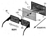
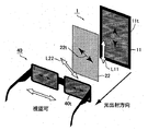
図2に示すように、一般の液晶表示装置101には偏光素子22が設けられておらず、偏光素子11から出射された直線偏光L11を観察者は見ることとなる。偏光サングラス40をかけた状態で観察すると、直線偏光L11の振動方向、すなわち、偏光素子11の透過軸11tと、偏光サングラス40の透過軸40tとが、略平行(ランドスケープモード)である場合は、直線偏光L11は偏光サングラス40を透過するため観察者は液晶表示装置101からの画像を視認することができる。一方、図3に示すように、偏光素子11の透過軸11tと、偏光サングラス40の透過軸40tとが、略垂直(ポートレートモード)である場合は、直線偏光L11は偏光サングラス40に吸収されるため、表示が暗くなり、観察者は液晶表示装置101からの画像を視認できなくなる。As shown in FIG. 2, the general liquid
それに対して、液晶表示装置1では、偏光素子11の観察面側に更に偏光素子22が設けられている。したがって、偏光素子11から出射された直線偏光の振動方向を偏光素子22によって適宜変更することができる。具体的には、表示画面(略方形の画面)の辺に対して斜め方向(例えば、略45°方向)に変更することができる。On the other hand, in the liquid crystal display device 1, a
ここで、二枚の偏光素子の透過率は、二枚の偏光素子の吸収軸のなす角がΘのときの透過率をT(Θ)で表す場合、下記式(1)で表される。
T(Θ)=1/2{(Tp1・Tp2+Tc1・Tc2)cos2Θ+(Tp1・Tc2+Tc2・Tp2)sin2Θ} (1)
式(1)において、Tp1は、一枚目の偏光素子の透過軸方向に平行な直線偏光を入射させた場合の透過率を、Tc1は、一枚目の偏光素子の吸収軸方向に平行な直線偏光を入射させた場合の透過率を、Tp2は、二枚目の偏光素子の透過軸方向に平行な直線偏光を入射させた場合の透過率を、Tc2は、二枚目の偏光素子の吸収軸方向に平行な直線偏光を入射させた場合の透過率を表す。Here, the transmittance of the two polarizing elements is expressed by the following formula (1) when the transmittance when the angle formed by the absorption axes of the two polarizing elements is Θ is represented by T (Θ).
T (Θ) = 1/2 {(Tp1 · Tp2 + Tc1 · Tc2) cos 2 Θ + (Tp1 · Tc2 + Tc2 · Tp2) sin 2 Θ} (1)
In Expression (1), Tp1 is the transmittance when linearly polarized light parallel to the transmission axis direction of the first polarizing element is incident, and Tc1 is parallel to the absorption axis direction of the first polarizing element. The transmittance when linearly polarized light is incident, Tp2 is the transmittance when linearly polarized light parallel to the transmission axis direction of the second polarizing element is incident, and Tc2 is the transmittance of the second polarizing element. It represents the transmittance when linearly polarized light parallel to the absorption axis direction is incident.
そのため、図4及び5に示すように、偏光素子11から出射された直線偏光L11の振動方向は、偏光素子22によって変更され、偏光素子22から出射された直線偏光L22の振動方向は、表示画面の辺に対して斜め方向となる。したがって、ランドスケープモード及びポートレートモードのいずれの場合でも、直線偏光L22の振動方向、すなわち偏光素子22の透過軸22tと、偏光サングラス40の透過軸40tとが、略平行又は略垂直とならず、上記式(1)で示したように、直線偏光L22の一部は、偏光サングラス40を透過することができる。すなわち、液晶表示装置1をいずれのモードに設置しようとも偏光サングラス40を掛けた状態で画像を視認することができる。このように、液晶表示装置1によれば、偏光サングラス40を掛けた状態で観察しても、画面の向きに起因する視認性の変化を小さくすることができる。Therefore, as shown in FIGS. 4 and 5, the vibration direction of the linearly polarized light L11 emitted from the
また、液晶表示装置1は、偏光サングラス等の偏光作用を持つ光学部材を通して画面を視認した場合に上記効果を奏することができる。したがって、液晶表示装置1は、偏光サングラスを使用する環境、例えば、外光が入射するような環境において使用されることが好ましい。なかでも好適な用途としては、デジタルサイネージが挙げられる。Moreover, the liquid crystal display device 1 can exhibit the above-described effect when the screen is viewed through an optical member having a polarizing action such as polarized sunglasses. Therefore, the liquid crystal display device 1 is preferably used in an environment where polarized sunglasses are used, for example, an environment where external light is incident. Among them, a suitable use is digital signage.
また、偏光素子の波長分散は、通常、位相差板よりも小さい。したがって、偏光素子22を使用したとしても色付きの発生を抑制することができる。Further, the wavelength dispersion of the polarizing element is usually smaller than that of the retardation plate. Therefore, even if the
また、液晶表示装置1は、偏光素子11と偏光素子22との間に、保護板21と、光学異方層23としての1/4波長板とを具備している。1/4波長板は、直線偏光を円偏光に変換する効果(機能)をもつ。In addition, the liquid crystal display device 1 includes a
液晶表示装置1の好適な用途としては、デジタルサイネージが挙げられるが、液晶表示パネル10がむき出しであると、この用途では通常の家庭向け用途に比べて破損してしまう可能性が高くなる。そこで、保護板21を設けて液晶表示パネル10を保護することが好ましい。A suitable use of the liquid crystal display device 1 is digital signage. However, if the liquid
他方、保護板21を液晶表示装置1の最表面に設けると、保護板21の界面(表面)で反射が発生する。すなわち、保護板21を具備することによって液晶表示装置1の界面の数は増加し、外光の反射が増加する。その結果、表示品位が低下してしまう。そこで、図6に示すように、1/4波長板24と偏光素子22とを合わせて円偏光板として機能させる。これにより、上述の外光の反射の増加を抑制することができる。また、偏光素子11表面での反射も抑制することができる。On the other hand, when the
(液晶表示パネル)
液晶表示パネル10は、液晶セル12、偏光素子11及び13を具備する。液晶表示パネル10の液晶モードは、偏光素子11の偏光軸(吸収軸、もしくは透過軸)が表示画面(略方形の画面)の辺に対して左右方向(水平方向、0°方向)、もしくは上下方向(垂直方向、90°方向)にあるものが好ましい。これにより、表示品位に優れたVAモード、IPSモード、FFSモード等の液晶モードを採用することができる。(LCD panel)
The liquid
なお、液晶セル12は、二枚の基板と、両基板の間に狭持された液晶層とを有する。The
偏光素子11及び13には、それらを保護するための保護フィルムが備えられていてもよいし、備えられていなくてもよいが、湿気等から偏光素子11及び13を保護するという観点からは、保護フィルムは備えられていることが好ましい。その場合、液晶セル12側から、粘着層\セル側保護フィルム\偏光素子11又は13\外側保護フィルムの順に積層される。The
(セル側保護フィルム)
上記セル側保護フィルムは、視野角補償のための位相差フィルムの役割を兼ね備えていてもよい。具体的には、VAモードの液晶表示パネルにおいては、nx>ny≒nzの関係を持つ位相差フィルムと、nx≒ny>nzの関係を持つ位相差フィルムとの組み合わせや、nx>ny>nzの関係をそれぞれ持つ二枚の位相差フィルムの組み合わせ、nx>ny>nzの関係を持つ位相差フィルムとnx≒ny>nzの関係を持つ位相差フィルムとの組み合わせ等が挙げられる。また、IPSモード、FFSモードの液晶表示パネルにおいては、nx>ny≒nzの関係を持つ位相差フィルムと、nz>nx≒nyの関係を持つ位相差フィルムとの組み合わせや、nx>nz>nyの関係を持つ位相差フィルムと、nx≒ny≧nzの関係を持つ位相差フィルムとの組み合わせ等が挙げられる。(Cell side protective film)
The cell-side protective film may also serve as a retardation film for viewing angle compensation. Specifically, in a VA mode liquid crystal display panel, a combination of a retardation film having a relationship of nx> ny≈nz and a retardation film having a relationship of nx≈ny> nz, or nx>ny> nz A combination of two retardation films each having the following relationship, a combination of a retardation film having a relationship of nx>ny> nz and a retardation film having a relationship of nx≈ny> nz. In the IPS mode and FFS mode liquid crystal display panels, a combination of a retardation film having a relationship of nx> ny≈nz and a retardation film having a relationship of nz> nx≈ny, or nx>nz> ny And a combination of a retardation film having a relationship of nx≈ny ≧ nz and the like.
なお、上記「ny≒nz」、「nx≒ny」とは、nyとnz、あるいはnxとnyが完全に同一である場合だけでなく、実質的に同一である場合も含まれる。たとえば、(ny−nz)×dが−10nm〜+10nm、好ましくは−5nm〜+5nmの場合も「ny≒nz」に含まれ、|nx−ny|×dが10nm以下、好ましくは5nm以下の場合も「nx≒ny」に含まれる。Note that “ny≈nz” and “nx≈ny” include not only the case where ny and nz, or nx and ny are completely the same, but also the case where they are substantially the same. For example, the case where (ny−nz) × d is −10 nm to +10 nm, preferably −5 nm to +5 nm is also included in “ny≈nz”, and | nx−ny | × d is 10 nm or less, preferably 5 nm or less Is also included in “nx≈ny”.
上記nx>ny≒nzの関係を持つ位相差フィルム、nx>ny>nzの関係を持つ位相差フィルムとしては、一般に正の複屈折を有するポリマーを延伸したものが用いられる。As the retardation film having a relationship of nx> ny≈nz and the retardation film having a relationship of nx> ny> nz, generally a stretched polymer having positive birefringence is used.
ここで、「正の複屈折を有するポリマー」とは、ポリマーを延伸等の方法により配向させた場合に、その配向方向の屈折率が相対的に大きくなるポリマーをいい、多くのポリマーがこれに該当する。正の複屈折を有するポリマーとしては、例えば、ポリカーボネート系樹脂、ポリビニルアルコール系樹脂、セルロース系樹脂、ポリエステル系樹脂、ポリイミド系樹脂、環状ポリオレフィン系樹脂、ポリスルホン系樹脂等が挙げられる。セルロース系樹脂としては、トリアセチルセルロース、ジアセチルセルロース等が挙げられる。ポリエステル系樹脂としては、ポリエチレンテレフタレート、ポリエチレンナフタレート等が挙げられる。特に、非晶質で耐熱性に優れるポリマーを好ましく用いることができる。これらのポリマーは、一種を単独で用いることもできるし、二種以上を混合して用いることもできる。Here, the “polymer having positive birefringence” refers to a polymer in which the refractive index in the orientation direction becomes relatively large when the polymer is oriented by a method such as stretching, and many polymers include this. Applicable. Examples of the polymer having positive birefringence include polycarbonate resins, polyvinyl alcohol resins, cellulose resins, polyester resins, polyimide resins, cyclic polyolefin resins, polysulfone resins, and the like. Examples of the cellulose resin include triacetyl cellulose and diacetyl cellulose. Examples of the polyester resin include polyethylene terephthalate and polyethylene naphthalate. In particular, an amorphous polymer having excellent heat resistance can be preferably used. These polymers can be used alone or in a combination of two or more.
上記nx>nz>nyの関係を持つ位相差フィルムとしては、一般に負の複屈折を有するポリマーを延伸したものが用いられる。As the retardation film having the relationship of nx> nz> ny, a film obtained by stretching a polymer having negative birefringence is generally used.
ここで、「負の複屈折を有するポリマー」とは、ポリマーを延伸等の方法により配向させた場合に、その配向方向の屈折率が相対的に小さくなる、換言すると、配向方向と直交する方向の屈折率が大きくなるポリマーをいう。このようなポリマーとしては、例えば、芳香族、カルボニル基等の分極異方性の大きい化学結合及び/又は官能基がポリマーの側鎖に導入されているものが挙げられる。具体的には、アクリル系樹脂、スチレン系樹脂、マレイミド系樹脂等が挙げられる。Here, “a polymer having negative birefringence” means that when the polymer is oriented by a method such as stretching, the refractive index in the orientation direction becomes relatively small, in other words, the direction orthogonal to the orientation direction. The polymer whose refractive index increases. Examples of such a polymer include those in which a chemical bond and / or a functional group having a large polarization anisotropy such as an aromatic group or a carbonyl group is introduced into a side chain of the polymer. Specific examples include acrylic resins, styrene resins, maleimide resins, and the like.
(外側保護フィルム)
上記外側保護フィルムとしては、偏光素子11及び13の保護層として機能し得る、任意の適切なフィルムを採用することができる。このようなフィルムに使用されるポリマーとしては、例えば、セルロース系樹脂、ポリカーボネート系樹脂、ポリビニルアルコール系樹脂、ポリスルホン系樹脂、ポリスチレン系樹脂、環状ポリオレフィン系樹脂等が挙げられる。セルロース系樹脂としては、トリアセチルセルロース、ジアセチルセルロース等が挙げられる。(Outer protective film)
Any appropriate film that can function as a protective layer for the
偏光素子11に設けられた外側保護フィルムの偏光素子11と逆の面には、ハードコート処理、反射防止処理、スティッキング防止や拡散、アンチグレアを目的とした処理等の表面処理が施されていてもよい。これにより、表面処理されていた液晶表示パネルをそのまま本実施形態の液晶表示パネル10として利用することができる。The surface opposite to the
また、偏光素子13に設けられた外側保護フィルムの偏光素子13と逆の面にも、同様の表面処理が施されていてもよい。装置の薄型化のため、液晶表示パネル10とバックライトユニット30とは貼り合わせられてもよいが、この場合、画面にバックライトユニット30の輝度ムラに起因する干渉縞(ニュートンリング)が発生することがある。表面処理を施すことにより、その発生を抑制することができる。Further, the same surface treatment may be applied to the surface of the outer protective film provided on the
なお、ハードコート処理は、外側保護フィルム表面の傷つき防止等を目的に施されるものであり、例えばアクリル系樹脂、シリコーン系樹脂等の紫外線硬化型樹脂を用いて硬度、滑り特性等の特性に優れる硬化皮膜(ハードコート層)を外側保護フィルムの表面に付加する方法にて行うことができる。In addition, the hard coat treatment is performed for the purpose of preventing the outer protective film surface from being scratched, etc., for example, by using an ultraviolet curable resin such as an acrylic resin, a silicone resin, etc., for characteristics such as hardness and sliding characteristics. It can be performed by a method of adding an excellent cured film (hard coat layer) to the surface of the outer protective film.
反射防止処理は、液晶表示装置表面での外光の反射防止を目的に施されるものであり、従来に準じた方法にて行うことができる。The antireflection treatment is performed for the purpose of preventing reflection of external light on the surface of the liquid crystal display device, and can be performed by a conventional method.
また、アンチグレア処理は、液晶表示装置表面で外光が反射して表示の視認性が阻害されることを防止すること等を目的に施されるものであり、例えば粗面化方式、透明微粒子の配合方式等の適宜な方式にて外側保護フィルムの表面に微細凹凸構造を付与することによって行うことができる。粗面化方式としては、サンドブラスト方式、エンボス加工方式等が挙げられる。The anti-glare treatment is performed for the purpose of preventing external light from being reflected on the surface of the liquid crystal display device and obstructing the visibility of the display. It can carry out by providing a fine uneven structure on the surface of the outer protective film by an appropriate method such as a blending method. Examples of the roughening method include a sand blast method and an embossing method.
(偏光素子11、13)
偏光素子11及び13としては、直交する直線偏光のうち、透過軸に平行な振動面を有する偏光をそのまま透過させ、吸収軸に平行な振動面を有する偏光を選択的に吸収する素子を用いることができる。このような偏光素子としては、例えば、親水性高分子フィルムに二色性物質を吸着させて幅方向に延伸処理したもの、リオトロピック液晶性を示す二色性色素が配向しているもの、ホモジニアス配向したサーモトロピック液晶ポリマー又はホモジニアス配向した架橋性液晶ポリマーのマトリックス中に二色性色素が配向しているもの等が挙げられる。(
As the
このような偏光素子の中でも、高い偏光度を実現するという観点からは、ヨウ素を含有するポリビニルアルコール系偏光素子が好適に用いられる。偏光素子に適用されるポリビニルアルコール系フィルムの材料には、ポリビニルアルコール又はその誘導体が用いられる。ポリビニルアルコールの誘導体としては、ポリビニルホルマール、ポリビニルアセタール等が挙げられる他、オレフィン、不飽和カルボン酸、該酸のアルキルエステル、該酸のアクリルアミド等で変性したものが挙げられる。オレフィンとしては、エチレン、プロピレン等が挙げられ、不飽和カルボン酸としては、アクリル酸、メタクリル酸、クロトン酸等が挙げられる。ポリビニルアルコールの重合度は、1000〜10000程度、ケン化度は80〜100モル%程度のものが一般に用いられる。Among such polarizing elements, a polyvinyl alcohol polarizing element containing iodine is preferably used from the viewpoint of realizing a high degree of polarization. Polyvinyl alcohol or a derivative thereof is used as the material for the polyvinyl alcohol film applied to the polarizing element. Derivatives of polyvinyl alcohol include polyvinyl formal, polyvinyl acetal, and the like, as well as olefins, unsaturated carboxylic acids, alkyl esters of the acids, acrylamides of the acids, and the like. Examples of the olefin include ethylene and propylene, and examples of the unsaturated carboxylic acid include acrylic acid, methacrylic acid, and crotonic acid. Polyvinyl alcohol having a polymerization degree of about 1000 to 10000 and a saponification degree of about 80 to 100 mol% is generally used.
上記ポリビニルアルコール系フィルムは、可塑剤等の添加剤を含有することもできる。可塑剤としては、ポリオール及びその縮合物等が挙げられ、例えばグリセリン、ジグリセリン、トリグリセリン、エチレングリコール、プロピレングリコール、ポリエチレングリコール等が挙げられる。可塑剤の使用量は、特に制限されないがポリビニルアルコール系フィルム中20重量%以下とするのが好適である。The said polyvinyl alcohol-type film can also contain additives, such as a plasticizer. Examples of the plasticizer include polyols and condensates thereof, and examples thereof include glycerin, diglycerin, triglycerin, ethylene glycol, propylene glycol, and polyethylene glycol. The amount of the plasticizer used is not particularly limited, but is preferably 20% by weight or less in the polyvinyl alcohol film.
上記ポリビニルアルコール系フィルム(未延伸フィルム)は、従来に準じた方法にて、一軸延伸処理及びヨウ素染色処理が少なくとも施される。更には、ホウ酸処理、ヨウ素イオン処理を施すことができる。また、上記処理後のポリビニルアルコール系フィルム(延伸フィルム)は、従来に準じた方法に従って乾燥されて偏光素子となる。The polyvinyl alcohol-based film (unstretched film) is at least subjected to uniaxial stretching treatment and iodine dyeing treatment by a conventional method. Furthermore, boric acid treatment and iodine ion treatment can be performed. Moreover, the polyvinyl alcohol-type film (stretched film) after the said process is dried in accordance with the method according to the former, and becomes a polarizing element.
一軸延伸処理における延伸方法は特に制限されず、湿潤延伸法と乾式延伸法のいずれも採用できる。乾式延伸法の延伸手段としては、例えば、ロール間延伸方法、加熱ロール延伸方法、圧縮延伸方法等が挙げられる。延伸は多段で行うこともできる。上記延伸手段において、未延伸フィルムは、通常、加熱状態とされる。通常、未延伸フィルムは厚み30〜150μm程度のものが用いられる。延伸フィルムの延伸倍率は目的に応じて適宜に設定できるが、延伸倍率(総延伸倍率)は2〜8倍程度であり、好ましくは3〜6.5倍であり、更に好ましくは3.5〜6倍である。延伸フィルムの厚さは5〜40μm程度が好適である。The stretching method in the uniaxial stretching treatment is not particularly limited, and either a wet stretching method or a dry stretching method can be employed. Examples of the stretching means of the dry stretching method include an inter-roll stretching method, a heated roll stretching method, and a compression stretching method. Stretching can also be performed in multiple stages. In the stretching means, the unstretched film is usually in a heated state. Usually, an unstretched film having a thickness of about 30 to 150 μm is used. The stretch ratio of the stretched film can be appropriately set according to the purpose, but the stretch ratio (total stretch ratio) is about 2 to 8 times, preferably 3 to 6.5 times, and more preferably 3.5 to 6 times. The thickness of the stretched film is preferably about 5 to 40 μm.
ヨウ素染色処理は、ポリビニルアルコール系フィルムをヨウ素及びヨウ化カリウムを含有するヨウ素溶液に浸漬することによって行われる。ヨウ素溶液は、通常、ヨウ素水溶液であり、ヨウ素と溶解助剤としてヨウ化カリウムとを含有する。ヨウ素濃度は0.01〜1重量%程度であり、好ましくは0.02〜0.5重量%であり、ヨウ化カリウム濃度は0.01〜10重量%程度であり、好ましくは0.02〜8重量%である。The iodine staining treatment is performed by immersing the polyvinyl alcohol film in an iodine solution containing iodine and potassium iodide. The iodine solution is usually an iodine aqueous solution, and contains iodine and potassium iodide as a dissolution aid. The iodine concentration is about 0.01 to 1% by weight, preferably 0.02 to 0.5% by weight, and the potassium iodide concentration is about 0.01 to 10% by weight, preferably 0.02 to 8% by weight.
ヨウ素染色処理において、ヨウ素溶液の温度は、通常20〜50℃程度であり、好ましくは25〜40℃である。浸漬時間は通常10〜300秒間程度であり、好ましくは20〜240秒間の範囲である。ヨウ素染色処理においては、ヨウ素溶液の濃度、ポリビニルアルコール系フィルムのヨウ素溶液への浸漬温度、浸漬時間等の条件を調整することによってポリビニルアルコール系フィルムにおけるヨウ素含有量及びカリウム含有量が上記範囲になるように調整する。ヨウ素染色処理は、一軸延伸処理の前、一軸延伸処理中、一軸延伸処理の後の何れの段階で行ってもよい。In the iodine dyeing treatment, the temperature of the iodine solution is usually about 20 to 50 ° C, preferably 25 to 40 ° C. The immersion time is usually about 10 to 300 seconds, preferably in the range of 20 to 240 seconds. In the iodine dyeing treatment, the iodine content and potassium content in the polyvinyl alcohol film are within the above ranges by adjusting the conditions such as the concentration of the iodine solution, the immersion temperature of the polyvinyl alcohol film in the iodine solution, and the immersion time. Adjust as follows. The iodine dyeing process may be performed at any stage before the uniaxial stretching process, during the uniaxial stretching process, or after the uniaxial stretching process.
ホウ酸処理は、ホウ酸水溶液へポリビニルアルコール系フィルムを浸漬することによって行う。ホウ酸水溶液中のホウ酸濃度は、2〜15重量%程度であり、好ましくは3〜10重量%である。ホウ酸水溶液中には、ヨウ化カリウムを用いて、カリウムイオン及びヨウ素イオンを含有させることができる。ホウ酸水溶液中のヨウ化カリウム濃度は0.5〜10重量%程度であり、好ましくは1〜8重量%である。ヨウ化カリウムを含有するホウ酸水溶液を用いることによって、着色の少ない偏光素子、すなわち可視光のほぼ全波長域に亘って吸光度がほぼ一定のいわゆるニュートラルグレーの偏光素子を得ることができる。The boric acid treatment is performed by immersing a polyvinyl alcohol film in an aqueous boric acid solution. The boric acid concentration in the boric acid aqueous solution is about 2 to 15% by weight, preferably 3 to 10% by weight. In the boric acid aqueous solution, potassium ion and iodine ion can be contained using potassium iodide. The potassium iodide concentration in the boric acid aqueous solution is about 0.5 to 10% by weight, preferably 1 to 8% by weight. By using a boric acid aqueous solution containing potassium iodide, it is possible to obtain a polarizing element with little coloration, that is, a so-called neutral gray polarizing element in which the absorbance is substantially constant over almost the entire wavelength range of visible light.
ヨウ素イオン処理には、例えば、ヨウ化カリウム等の化合物を用いてヨウ素イオンを含有させた水溶液を用いる。ヨウ化カリウム濃度は0.5〜10重量%程度であり、好ましくは1〜8重量%である。ヨウ素イオン含浸処理において、その水溶液の温度は、通常15〜60℃程度であり、好ましくは25〜40℃である。浸漬時間は通常1〜120秒間程度であり、好ましくは3〜90秒間の範囲である。ヨウ素イオン処理は、乾燥工程前であれば何れの段階で行ってもよい。後述の水洗浄後に行うこともできる。For the iodine ion treatment, for example, an aqueous solution containing iodine ions using a compound such as potassium iodide is used. The potassium iodide concentration is about 0.5 to 10% by weight, preferably 1 to 8% by weight. In the iodine ion impregnation treatment, the temperature of the aqueous solution is usually about 15 to 60 ° C, and preferably 25 to 40 ° C. The immersion time is usually about 1 to 120 seconds, preferably 3 to 90 seconds. The iodine ion treatment may be performed at any stage before the drying step. It can also be performed after water washing described later.
また、偏光素子には亜鉛を含有させることもできる。偏光素子に亜鉛を含有させることは、加熱耐久時における色相劣化抑制の点で好ましい。耐久性の向上と、色相の劣化抑制とを実現する観点からは、偏光素子中の亜鉛の含有量は、亜鉛元素が、偏光素子中に0.002〜2重量%含有される程度に調整することが好ましく、0.01〜1重量%に調整することがより好ましい。The polarizing element can also contain zinc. Inclusion of zinc in the polarizing element is preferable in terms of suppressing hue deterioration during heating durability. From the viewpoint of realizing improvement in durability and suppression of deterioration of hue, the content of zinc in the polarizing element is adjusted so that the zinc element is contained in the polarizing element in an amount of 0.002 to 2% by weight. It is preferable to adjust to 0.01 to 1% by weight.
前記処理の施されたポリビニルアルコール系フィルム(延伸フィルム)は、従来に準じた方法にて、水洗浄工程、乾燥工程に供することができる。The treated polyvinyl alcohol film (stretched film) can be subjected to a water washing step and a drying step by a conventional method.
水洗浄工程は、通常、純水にポリビニルアルコール系フィルムを浸漬することによって行う。水洗浄温度は、通常、5〜50℃であり、好ましくは10〜45℃であり、より好ましくは15〜40℃の範囲である。浸漬時間は、通常、10〜300秒間であり、好ましくは20〜240秒間程度である。The water washing step is usually performed by immersing a polyvinyl alcohol film in pure water. The water washing temperature is usually 5 to 50 ° C, preferably 10 to 45 ° C, and more preferably 15 to 40 ° C. The immersion time is usually 10 to 300 seconds, preferably about 20 to 240 seconds.
乾燥工程は、任意の適切な乾燥方法、例えば、自然乾燥、送風乾燥、加熱乾燥等を採用し得る。例えば、加熱乾燥の場合には、乾燥温度は代表的には20〜80℃であり、好ましくは25〜70℃であり、乾燥時間は代表的には1〜10分間程度であることが好ましい。また、乾燥後の偏光素子の水分率は10〜30重量%とすることが好ましく、12〜28重量%とすることがより好ましく、16〜25重量%とすることが更に好ましい。水分率が過度に大きいと、接着層を介して、偏光素子と、セル側保護フィルム及び/又は外側保護フィルム(通常は、セル側保護フィルム及び外側保護フィルム)とを貼り合わせた積層貼合体、すなわち偏光板を乾燥する際に、偏光素子の乾燥に伴って偏光度が低下する傾向がある。特に500nm以下の短波長領域における直交透過率が増大する、すなわち、短波長の光が漏れるために、黒表示が青色に着色する傾向がある。逆に、偏光素子の水分率が過度に小さいと、局所的な凹凸欠陥(クニック欠陥)が発生することがある。Arbitrary appropriate drying methods, for example, natural drying, ventilation drying, heat drying etc., can be employ | adopted for a drying process. For example, in the case of heat drying, the drying temperature is typically 20 to 80 ° C., preferably 25 to 70 ° C., and the drying time is typically about 1 to 10 minutes. The moisture content of the polarizing element after drying is preferably 10 to 30% by weight, more preferably 12 to 28% by weight, and still more preferably 16 to 25% by weight. When the moisture content is excessively large, a laminated laminate in which a polarizing element and a cell-side protective film and / or an outer protective film (usually, a cell-side protective film and an outer protective film) are bonded via an adhesive layer, That is, when the polarizing plate is dried, the degree of polarization tends to decrease with drying of the polarizing element. In particular, the orthogonal transmittance increases in a short wavelength region of 500 nm or less, that is, light of a short wavelength leaks, so that black display tends to be colored blue. On the contrary, when the moisture content of the polarizing element is excessively small, local unevenness defects (knic defects) may occur.
(光学異方層)
光学異方層23は、直線偏光を円偏光に変換するものであることが好ましい。ここで、「円偏光」とは、完全な円偏光のみならず、完全な円偏光に近い偏光、すなわち楕円率が1に近い楕円偏光をも含み得る。完全な円偏光は、例えば、直線偏光が、ある特定の光学異方層(以下、第一の光学異方層という)を透過した場合に得られる。ただし、第一の光学異方層の遅相軸は、該直線偏光の振動方向に対して45°の角度をなし、第一の光学異方層のリタデーションは、137.5nm(1/4波長)である。また、上記円偏光は、直線偏光が、ある特定の光学異方層(以下、第二の光学異方層という)を透過した場合に得られる楕円偏光を含むものである。ただし、第二の光学異方層の遅相軸は、該直線偏光の振動方向に対して45°の角度をなし、第二の光学異方層のリタデーションは、110〜180nmである。(Optically anisotropic layer)
The optical
なお、円偏光及び楕円偏光は、右回りであるか左回りであるかを問わない。また、偏光状態としては、必ずしも完全偏光であることを要さず、一部偏光していない状態を含む部分偏光であってもよい。In addition, it does not ask | require whether circularly polarized light and elliptically polarized light are clockwise or counterclockwise. Further, the polarization state does not necessarily need to be completely polarized, and may be partially polarized including a partially unpolarized state.
このように直線偏光を円偏光に変換する光学異方層23としては、1/4波長板24が好適であり、1/4波長板24(光学異方層23)のリタデーションは110〜180nmの範囲であることが好ましく、より好ましくは120〜170nmであり、更に好ましくは130〜150nmである。Thus, as the optically
また、直線偏光を円偏光に変換し、保護板21を配置したことにより増加した界面反射を効果的に低減させるという観点からは、光学異方層23(1/4波長板24)の遅相軸と、偏光素子22の吸収軸とのなす角は、40〜50°であることが好ましく、42〜48°であることがより好ましく、43〜47°であることが更に好ましく、44〜46°であることが特に好ましい。Further, from the viewpoint of effectively reducing the interface reflection that has been increased by converting the linearly polarized light into circularly polarized light and arranging the
光学異方層23(1/4波長板24)の遅相軸と、偏光素子11の吸収軸とは略平行に配置されることが好ましい。これにより、偏光素子11から出射された光(表示光)に対して光学異方層23(1/4波長板24)が不必要に影響を及ぼさないようにすることができる。It is preferable that the slow axis of the optically anisotropic layer 23 (¼ wavelength plate 24) and the absorption axis of the
(偏光素子22)
偏光素子22は、偏光素子11及び13と同様の方法で作製することができる。なかでも、偏光素子22としては、上述のヨウ素を含有するポリビニルアルコール系偏光素子(ヨウ素系偏光素子)、染料系偏光素子が好適であり、これにより、可視光領域の透過スペクトルをフラット(略均一)にすることができ、色付きの発生を効果的に抑制することができる。また、ワイヤーグリッド、輝度向上フィルム(例えば、3M社製のDBEF)等の偏光素子も透過スペクトルが比較的フラットであり、偏光素子22として使用可能である。なかでも、偏光素子22と1/4波長板24とによる円偏光板を用いて反射防止を行うという観点からは、ヨウ素系偏光素子が特に好ましい。ヨウ素系偏光素子は、ある程度の偏光度を確保できるからである。また、染料系偏光素子の偏光度も比較的高く、また、この偏光素子の耐熱性といった耐環境性は高い。したがって、染料系偏光素子は、デジタルサイネージの用途を想定した液晶表示装置1の偏光素子22に適している。(Polarizing element 22)
The
ランドスケープモード及びポートレートモードのいずれの場合でも、偏光サングラスを掛けた状態での視認性を充分に確保する観点からは、偏光素子11の吸収軸と、偏光素子22の吸収軸とのなす角は、20〜70°であることが好ましい。In both the landscape mode and the portrait mode, from the viewpoint of sufficiently ensuring the visibility in the state of wearing the polarized sunglasses, the angle formed between the absorption axis of the
また、ランドスケープモード及びポートレートモードの間での輝度変化を小さくするという観点からは、偏光素子11の吸収軸と、偏光素子22の吸収軸とのなす角は、30〜60°であることがより好ましく、35〜55°であることが更に好ましく、40〜50°であることが特に好ましく、略45°であることが最も好ましい。Further, from the viewpoint of reducing the luminance change between the landscape mode and the portrait mode, the angle formed by the absorption axis of the
偏光素子22の観察面側には、偏光素子22を保護するための保護フィルムが備えられていてもよいし、備えられていなくてもよいが、偏光素子22を保護する観点からは保護フィルムが備えられていることが好ましい。偏光素子22の保護フィルムとしては、上述の外側保護フィルムと同様のものを用いることができる。On the observation surface side of the
偏光素子22の観察面側の表面は、ハードコート処理、反射防止処理、スティッキング防止や拡散、アンチグレアを目的とした処理等の上述の表面処理が施されていることが好ましい。The surface on the observation surface side of the
なかでも、液晶表示装置1の最表面での反射を特に好適に低減させるという観点からは、偏光素子22の観察面側の表面は、反射防止処理として、アンチグレア機能を持たせたモスアイ構造を付与する処理が施されることが最も好ましい。Especially, from the viewpoint of reducing the reflection on the outermost surface of the liquid crystal display device 1 particularly preferably, the surface on the observation surface side of the
アンチグレア機能を持たせたモスアイ構造は、例えば、以下の工程により形成することができる。まず、粗面化方式により表面に微細な凹凸をつけたアルミニウム基板(粗面基板)を作製する。粗面化方式としては、サンドブラスト方式、エンボス加工方式等が挙げられる。次に、上記アルミニウム基板を陽極酸化することによって複数の微細な凹部を有するポーラスアルミナ層を形成する工程と、上記ポーラスアルミナ層をアルミナのエッチャントに接触させることによって上記微細な凹部を拡大させる工程とを繰り返す。これにより、アルミニウム基板に複数の微細な円柱状の凹部が形成された金型を作製することができる。そして、トリアセチルセルロース等の基材フィルム上に塗布したUV硬化樹脂膜に上記金型を押し当てた状態でUV照射することによって、円柱状の凹凸構造(モスアイ構造)を樹脂膜表面に転写する。なお、上記粗面基板の代わりに鏡面加工されたアルミニウム基板を用いてもよいが、表面反射をより効果的に抑制する観点からは、粗面基板を用いることが好ましい。A moth-eye structure having an antiglare function can be formed by, for example, the following steps. First, an aluminum substrate (rough substrate) having a surface with fine irregularities is produced by a roughening method. Examples of the roughening method include a sand blast method and an embossing method. Next, anodizing the aluminum substrate to form a porous alumina layer having a plurality of fine recesses, and enlarging the fine recesses by contacting the porous alumina layer with an alumina etchant; repeat. Thereby, the metal mold | die with which the some fine cylindrical recessed part was formed in the aluminum substrate is producible. Then, the cylindrical concavo-convex structure (moth eye structure) is transferred to the surface of the resin film by irradiating the UV curable resin film coated on a base film such as triacetyl cellulose with the mold pressed against the UV mold. . Note that a mirror-finished aluminum substrate may be used instead of the rough surface substrate, but it is preferable to use a rough surface substrate from the viewpoint of more effectively suppressing surface reflection.
(保護板)
保護板21としては液晶表示パネル10を保護し得る透明な板(基材)であれば特に限定されず、その材料としては、例えば、アクリル系樹脂、無機ガラス、ポリカーボネート等が挙げられる。アクリル系樹脂としては、PMMA(ポリメチルメタクリレート)が挙げられる。(Protective plate)
The
なお、液晶表示パネル10と保護板21とは、硬化性樹脂等の接着剤を用いて貼り合わせることは可能であるが、気泡が発生することがある。そこで、両者を空気層を介して配置することにより、安価に装置の強度を向上することができる。The liquid
また、前面板20は、保護板21の代わりに、タッチパネルを有してもよい。Further, the
本実施形態の液晶表示装置1は、偏光素子13を有さない代わりに反射部材を有する反射型の液晶表示装置であってもよいが、この場合、光が偏光素子22を二度透過することになるため画面が暗くなる。一方、透過型の場合は、光は偏光素子22を一度透過するだけなので画面を明るくすることができる。The liquid crystal display device 1 of the present embodiment may be a reflective liquid crystal display device having a reflecting member instead of having the
(1/4波長板の作製)
長尺の環状ポリオレフィン系樹脂フィルム(日本ゼオン社製、商品名「ゼオノアフィルム」)を、140℃で周速の異なるロール間で1.52倍に一軸延伸することによって、長尺状の位相差フィルム(1/4波長板)を作成した。このフィルムの厚みは35μmであり、面内位相差Reは139nmであった。(Preparation of quarter wave plate)
A long phase difference is obtained by uniaxially stretching a long cyclic polyolefin-based resin film (manufactured by Nippon Zeon Co., Ltd., trade name “ZEONOR FILM”) at 140 ° C. between rolls having different peripheral speeds at 1.52 times. A film (1/4 wavelength plate) was prepared. The thickness of this film was 35 μm, and the in-plane retardation Re was 139 nm.
(前面板の作製)
得られた1/4波長板を市販の偏光板(日東電工社製、商品名「SEG1224DU」)に粘着層を介して貼り合わせた。このとき、1/4波長板の遅相軸と偏光板の吸収軸とのなす角が45°となるように設定した。なお、この偏光板は、ヨウ素系偏光フィルムを2枚のTACで挟持した構造を有する。(Preparation of front plate)
The obtained quarter-wave plate was bonded to a commercially available polarizing plate (manufactured by Nitto Denko Corporation, trade name “SEG1224DU”) via an adhesive layer. At this time, the angle formed by the slow axis of the quarter-wave plate and the absorption axis of the polarizing plate was set to 45 °. The polarizing plate has a structure in which an iodine polarizing film is sandwiched between two TACs.
得られた1/4波長板付き偏光板を保護板であるガラス基板に貼り合わせた。このとき、偏光板の吸収軸が、後述する液晶テレビの観察面側偏光板の吸収軸に対して45°の角度となるように設定した。The obtained polarizing plate with a quarter wavelength plate was bonded to a glass substrate as a protective plate. At this time, the absorption axis of the polarizing plate was set to an angle of 45 ° with respect to the absorption axis of the polarizing plate on the observation surface side of the liquid crystal television described later.
更に、1/4波長板の偏光板と反対の面に、アンチグレア機能を持たせたモスアイ構造を有する反射防止フィルムを貼り合わせることによって前面板を作製した。Further, an antireflection film having a moth-eye structure having an antiglare function was bonded to the surface opposite to the polarizing plate of the quarter wavelength plate to produce a front plate.
(液晶表示装置の作製)
市販の液晶テレビ(シャープ社製、商品名「LC−40AE6」)の観察面側に、上記前面板を配置し、実施例1の液晶表示装置を作製した。なお、上記液晶テレビの観察面側偏光板は、ヨウ素系偏光フィルムを2枚のTACで挟持した構造を有し、背面側偏光板は、ヨウ素系偏光フィルムを位相差フィルムとTACとで挟持した構造を有する。(Production of liquid crystal display device)
The front plate was arranged on the observation surface side of a commercially available liquid crystal television (manufactured by Sharp Corporation, trade name “LC-40AE6”), and the liquid crystal display device of Example 1 was produced. The polarizing plate on the observation surface side of the liquid crystal television has a structure in which an iodine polarizing film is sandwiched between two TACs, and the rear polarizing plate has a structure in which an iodine polarizing film is sandwiched between a retardation film and TAC. It has a structure.
[比較例1]
前面板を有さない市販の液晶テレビ(シャープ社製、商品名「LC−40AE6」)を比較例1の液晶表示装置とした。[Comparative Example 1]
A commercially available liquid crystal television (manufactured by Sharp Corporation, trade name “LC-40AE6”) having no front plate was used as the liquid crystal display device of Comparative Example 1.
[評価]
実施例1及び比較例1の液晶表示装置のコントラスト比(CR)と、白表示時の色度とを輝度計(TOPCON社製、商品名「BM−5A」)にて測定した。またこの測定においては、偏光サングラスを掛けて視認した場合を想定して、市販の偏光板(日東電工社製、商品名「SEG1224DU」)を輝度計の測定部の前面に設置した。測定は、液晶表示装置の画面を横長(ランドスケープモード)に配置した場合と、縦長(ポートレートモード)に配置した場合とについて行った。なお、偏光サングラスを想定して配置した偏光板の吸収軸は、水平方向に配置した。[Evaluation]
The contrast ratio (CR) of the liquid crystal display devices of Example 1 and Comparative Example 1 and the chromaticity at the time of white display were measured with a luminance meter (trade name “BM-5A” manufactured by TOPCON). In addition, in this measurement, a commercially available polarizing plate (manufactured by Nitto Denko Corporation, trade name “SEG1224DU”) was installed on the front surface of the measurement unit of the luminance meter, assuming the case of viewing with polarized sunglasses. The measurement was performed for the case where the screen of the liquid crystal display device was arranged horizontally (landscape mode) and the case where it was arranged vertically (portrait mode). In addition, the absorption axis of the polarizing plate arranged assuming polarized sunglasses was arranged in the horizontal direction.
実施例1及び比較例1の液晶表示装置の輝度及びコントラスト比(CR)を、測定した結果を下記表1に示す。Table 1 below shows the results of measuring the luminance and contrast ratio (CR) of the liquid crystal display devices of Example 1 and Comparative Example 1.

表1に示すように、実施例1の液晶表示装置においては、画面が横長(ランドスケープモード)の場合、縦長(ポートレートモード)の場合のいずれにおいても、輝度が充分にあり、表示画面が視認できた。また、偏光サングラスを掛けないで視認した場合においても、白表示の色付きはなかった。As shown in Table 1, in the liquid crystal display device according to the first embodiment, the brightness is sufficient in both the case where the screen is landscape (landscape mode) and the case where the screen is portrait (portrait mode). did it. Further, even when viewed without wearing polarized sunglasses, the white display was not colored.
一方、比較例1の液晶表示装置においては、画面が横長(ランドスケープモード)の場合には表示画面が視認できるが、縦長(ポートレートモード)の場合には視認できなかった。On the other hand, in the liquid crystal display device of Comparative Example 1, the display screen was visible when the screen was landscape (landscape mode), but was not visible when it was portrait (portrait mode).
このことから、実施例1の液晶表示装置は、偏光サングラス等の偏光レンズを掛けて表示画面を視認した場合でも、視認性に優れているといえる。From this, it can be said that the liquid crystal display device of Example 1 is excellent in visibility even when the display screen is viewed with a polarizing lens such as polarized sunglasses.
本願は、2009年12月3日に出願された日本国特許出願2009−275667号を基礎として、パリ条約ないし移行する国における法規に基づく優先権を主張するものである。該出願の内容は、その全体が本願中に参照として組み込まれている。This application claims the priority based on the Paris Convention or the laws and regulations in the country to which transition is based on Japanese Patent Application No. 2009-275667 filed on Dec. 3, 2009. The contents of the application are hereby incorporated by reference in their entirety.
1:液晶表示装置
10:液晶表示パネル
11、13:偏光素子
12:液晶セル
20:前面板
21:保護板
22:偏光素子
23:光学異方層
24:1/4波長板
30:バックライトユニット
40:偏光サングラス1: Liquid crystal display device 10: Liquid
Claims (6)
前記液晶表示装置は、前記第一の偏光素子の観察面側に設けられた第二の偏光素子と、前記第一の偏光素子及び前記第二の偏光素子の間に設けられた保護板と、前記第二の偏光素子及び前記保護板の間に設けられた光学異方層とを更に備えることを特徴とする液晶表示装置。A liquid crystal display device comprising a liquid crystal cell and a first polarizing element provided on the observation surface side of the liquid crystal cell,
The liquid crystal display device includes a second polarizing element provided on the observation surface side of the first polarizing element, a protective plate provided between the first polarizing element and the second polarizing element, The liquid crystal display device further comprising: an optical anisotropic layer provided between the second polarizing element and the protective plate .
Priority Applications (1)
| Application Number | Priority Date | Filing Date | Title |
|---|---|---|---|
| JP2010549966A JP4689769B1 (en) | 2009-12-03 | 2010-10-21 | Liquid crystal display |
Applications Claiming Priority (4)
| Application Number | Priority Date | Filing Date | Title |
|---|---|---|---|
| JP2009275667 | 2009-12-03 | ||
| JP2009275667 | 2009-12-03 | ||
| PCT/JP2010/068614 WO2011067993A1 (en) | 2009-12-03 | 2010-10-21 | Liquid crystal display device |
| JP2010549966A JP4689769B1 (en) | 2009-12-03 | 2010-10-21 | Liquid crystal display |
Related Child Applications (1)
| Application Number | Title | Priority Date | Filing Date |
|---|---|---|---|
| JP2011031070A Division JP2011138152A (en) | 2009-12-03 | 2011-02-16 | Liquid crystal display device |
Publications (2)
| Publication Number | Publication Date |
|---|---|
| JP4689769B1 true JP4689769B1 (en) | 2011-05-25 |
| JPWO2011067993A1 JPWO2011067993A1 (en) | 2013-04-18 |
Family
ID=44114852
Family Applications (2)
| Application Number | Title | Priority Date | Filing Date |
|---|---|---|---|
| JP2010549966A Active JP4689769B1 (en) | 2009-12-03 | 2010-10-21 | Liquid crystal display |
| JP2011031070A Pending JP2011138152A (en) | 2009-12-03 | 2011-02-16 | Liquid crystal display device |
Family Applications After (1)
| Application Number | Title | Priority Date | Filing Date |
|---|---|---|---|
| JP2011031070A Pending JP2011138152A (en) | 2009-12-03 | 2011-02-16 | Liquid crystal display device |
Country Status (7)
| Country | Link |
|---|---|
| US (1) | US20110199561A1 (en) |
| EP (1) | EP2508940A1 (en) |
| JP (2) | JP4689769B1 (en) |
| CN (1) | CN102159988A (en) |
| RU (2) | RU2450295C1 (en) |
| TW (1) | TW201128264A (en) |
| WO (1) | WO2011067993A1 (en) |
Cited By (2)
| Publication number | Priority date | Publication date | Assignee | Title |
|---|---|---|---|---|
| KR20150026280A (en) * | 2013-09-02 | 2015-03-11 | 삼성디스플레이 주식회사 | Display device |
| KR20170128266A (en) | 2015-03-16 | 2017-11-22 | 니폰 제온 가부시키가이샤 | Optical laminate, polarizing plate and liquid crystal display |
Families Citing this family (26)
| Publication number | Priority date | Publication date | Assignee | Title |
|---|---|---|---|---|
| JP4888853B2 (en) | 2009-11-12 | 2012-02-29 | 学校法人慶應義塾 | Method for improving visibility of liquid crystal display device, and liquid crystal display device using the same |
| KR101699497B1 (en) | 2010-06-22 | 2017-01-24 | 도요보 가부시키가이샤 | Liquid crystal display device, polarizing plate and polarizer protective film |
| JP2012189686A (en) * | 2011-03-09 | 2012-10-04 | Fujifilm Corp | Three dimensional display device, and three dimensional display system of time division system |
| WO2012157663A1 (en) | 2011-05-18 | 2012-11-22 | 東洋紡株式会社 | Liquid crystal display device, polarizing plate, and polarizer protection film |
| KR101833582B1 (en) | 2011-05-18 | 2018-02-28 | 도요보 가부시키가이샤 | Polarizing plate suitable for liquid crystal display device capable of displaying three-dimensional images, and liquid crystal display device |
| JP2013097041A (en) * | 2011-10-28 | 2013-05-20 | Dic Corp | Image display unit and protective film |
| WO2013100041A1 (en) * | 2011-12-28 | 2013-07-04 | 東洋紡株式会社 | Liquid-crystal display device, polarizer, and film for protecting polarizing element |
| US10094952B2 (en) | 2012-09-20 | 2018-10-09 | Sharp Kabushiki Kaisha | Anti-reflection film, method of producing the film and display device |
| JP2014153559A (en) * | 2013-02-08 | 2014-08-25 | Toyobo Co Ltd | Image display device |
| KR20150047359A (en) * | 2013-10-24 | 2015-05-04 | 삼성디스플레이 주식회사 | Display device |
| KR102271203B1 (en) * | 2013-12-23 | 2021-06-30 | 삼성디스플레이 주식회사 | Display device |
| WO2015186734A1 (en) * | 2014-06-05 | 2015-12-10 | シャープ株式会社 | Mirror display and mirror display unit |
| WO2016006507A1 (en) * | 2014-07-08 | 2016-01-14 | シャープ株式会社 | Mirror plate and mirror display |
| TWI560477B (en) * | 2014-12-12 | 2016-12-01 | Wistron Corp | Display module |
| KR20180131717A (en) * | 2017-05-31 | 2018-12-11 | 삼성디스플레이 주식회사 | Polarizer and manufacturing method thereof |
| KR102580799B1 (en) * | 2017-09-05 | 2023-09-20 | 삼성디스플레이 주식회사 | Polarizer and manufacturing method thereof |
| KR102651665B1 (en) * | 2017-11-30 | 2024-03-26 | 스미또모 가가꾸 가부시끼가이샤 | optically anisotropic film |
| CN107976837B (en) * | 2017-12-18 | 2021-12-07 | 华显光电技术(惠州)有限公司 | Polaroid and display device |
| JP7085414B2 (en) * | 2018-06-14 | 2022-06-16 | 住友化学株式会社 | Liquid crystal film manufacturing method and optical laminate manufacturing method |
| JP2020052335A (en) * | 2018-09-28 | 2020-04-02 | 東洋紡株式会社 | Oriented film, image display device using the same and method for cutting single oriented film |
| JPWO2021020159A1 (en) * | 2019-07-31 | 2021-02-04 | ||
| JP7405576B2 (en) * | 2019-11-21 | 2023-12-26 | 住友化学株式会社 | optically anisotropic film |
| JP7147820B2 (en) * | 2020-02-25 | 2022-10-05 | カシオ計算機株式会社 | display device and clock |
| EP3872579A1 (en) | 2020-02-25 | 2021-09-01 | Casio Computer Co., Ltd. | Wearable electronic device |
| CN111338124A (en) * | 2020-04-13 | 2020-06-26 | 武汉华星光电技术有限公司 | Quantum dot display panel, quantum dot display device and preparation method thereof |
| CN113946070A (en) * | 2021-09-26 | 2022-01-18 | 深圳市三利谱光电科技股份有限公司 | Phase delay polaroid, processing technology thereof and optical display device |
Citations (4)
| Publication number | Priority date | Publication date | Assignee | Title |
|---|---|---|---|---|
| JP2004004462A (en) * | 2002-04-26 | 2004-01-08 | Casio Comput Co Ltd | Display device |
| JP2005250061A (en) * | 2004-03-03 | 2005-09-15 | Hitachi Ltd | Optical unit, projection image display device and optical element used therefor |
| WO2008081919A1 (en) * | 2006-12-28 | 2008-07-10 | Sony Corporation | Optical compensation plate, liquid crystal display device, projection type liquid crystal display device, display device manufacturing method, and adjusting method |
| WO2009104414A1 (en) * | 2008-02-22 | 2009-08-27 | シャープ株式会社 | Display device |
Family Cites Families (14)
| Publication number | Priority date | Publication date | Assignee | Title |
|---|---|---|---|---|
| JPS629319A (en) * | 1985-07-06 | 1987-01-17 | Nitto Electric Ind Co Ltd | Liquid crystal display cell |
| JPH01204092A (en) * | 1988-02-10 | 1989-08-16 | Nissan Motor Co Ltd | Image display device for vehicle |
| JPH06258633A (en) * | 1993-03-04 | 1994-09-16 | Rohm Co Ltd | Liquid crystal display device |
| RU2226708C2 (en) * | 2001-09-21 | 2004-04-10 | ОПТИВА, Инк. | Liquid-crystal display with reflection polarizer |
| JP2003302532A (en) * | 2002-04-12 | 2003-10-24 | Mitsubishi Chemicals Corp | Polarizing plate and method for manufacturing the same |
| JP3687854B2 (en) * | 2002-10-15 | 2005-08-24 | 日東電工株式会社 | Optical film and liquid crystal display device |
| JP2004170875A (en) | 2002-11-22 | 2004-06-17 | Toshiba Matsushita Display Technology Co Ltd | Liquid crystal display device |
| JP5061901B2 (en) * | 2005-08-29 | 2012-10-31 | コニカミノルタアドバンストレイヤー株式会社 | Liquid crystal display |
| JP2007225648A (en) * | 2006-02-21 | 2007-09-06 | Sumitomo Chemical Co Ltd | Compound polarizing plate of wide viewing angle and liquid crystal display device |
| JP2008083115A (en) | 2006-09-26 | 2008-04-10 | Epson Imaging Devices Corp | Liquid crystal device and electronic apparatus |
| JP2009075533A (en) * | 2007-08-31 | 2009-04-09 | Nippon Oil Corp | Elliptic polarization plate and liquid crystal display device |
| JP4791434B2 (en) | 2007-11-15 | 2011-10-12 | 日東電工株式会社 | Liquid crystal display |
| JP2009122423A (en) | 2007-11-15 | 2009-06-04 | Toshiba Matsushita Display Technology Co Ltd | Liquid crystal display element |
| JP2009275667A (en) | 2008-05-16 | 2009-11-26 | Toyota Motor Corp | Emission control device of internal combustion engine |
-
2010
- 2010-10-21 RU RU2011118877/28A patent/RU2450295C1/en active
- 2010-10-21 US US13/120,224 patent/US20110199561A1/en not_active Abandoned
- 2010-10-21 JP JP2010549966A patent/JP4689769B1/en active Active
- 2010-10-21 WO PCT/JP2010/068614 patent/WO2011067993A1/en active Application Filing
- 2010-10-21 EP EP10834446A patent/EP2508940A1/en not_active Withdrawn
- 2010-10-21 CN CN2010800025507A patent/CN102159988A/en active Pending
- 2010-12-02 TW TW099141921A patent/TW201128264A/en not_active IP Right Cessation
-
2011
- 2011-02-16 JP JP2011031070A patent/JP2011138152A/en active Pending
-
2012
- 2012-01-30 RU RU2012103165/28A patent/RU2012103165A/en unknown
Patent Citations (4)
| Publication number | Priority date | Publication date | Assignee | Title |
|---|---|---|---|---|
| JP2004004462A (en) * | 2002-04-26 | 2004-01-08 | Casio Comput Co Ltd | Display device |
| JP2005250061A (en) * | 2004-03-03 | 2005-09-15 | Hitachi Ltd | Optical unit, projection image display device and optical element used therefor |
| WO2008081919A1 (en) * | 2006-12-28 | 2008-07-10 | Sony Corporation | Optical compensation plate, liquid crystal display device, projection type liquid crystal display device, display device manufacturing method, and adjusting method |
| WO2009104414A1 (en) * | 2008-02-22 | 2009-08-27 | シャープ株式会社 | Display device |
Cited By (3)
| Publication number | Priority date | Publication date | Assignee | Title |
|---|---|---|---|---|
| KR20150026280A (en) * | 2013-09-02 | 2015-03-11 | 삼성디스플레이 주식회사 | Display device |
| KR102053233B1 (en) * | 2013-09-02 | 2019-12-09 | 삼성디스플레이 주식회사 | Display device |
| KR20170128266A (en) | 2015-03-16 | 2017-11-22 | 니폰 제온 가부시키가이샤 | Optical laminate, polarizing plate and liquid crystal display |
Also Published As
| Publication number | Publication date |
|---|---|
| US20110199561A1 (en) | 2011-08-18 |
| RU2012103165A (en) | 2013-08-10 |
| EP2508940A1 (en) | 2012-10-10 |
| JPWO2011067993A1 (en) | 2013-04-18 |
| JP2011138152A (en) | 2011-07-14 |
| CN102159988A (en) | 2011-08-17 |
| TW201128264A (en) | 2011-08-16 |
| RU2450295C1 (en) | 2012-05-10 |
| WO2011067993A1 (en) | 2011-06-09 |
| TWI359310B (en) | 2012-03-01 |
Similar Documents
| Publication | Publication Date | Title |
|---|---|---|
| JP4689769B1 (en) | Liquid crystal display | |
| KR100679535B1 (en) | Polarizer, polarization plate and liquid crystal display apparatus using the same | |
| KR100757718B1 (en) | Optical film and liquid crystal display | |
| JP5512004B2 (en) | Liquid crystal display device, laminated polarizing plate, and polarized light source device | |
| KR100717563B1 (en) | Ips mode liquid crystal display device | |
| KR20070006863A (en) | Optical film and liquid crystal display device | |
| JP2005266696A (en) | Circular polarizing plate, optical film and image display device | |
| JP2005345958A (en) | Liquid crystal panel, polarizing plate and liquid crystal display | |
| JP2002258051A (en) | Polarizing plate and liquid crystal display device using the same | |
| JP2002202412A (en) | Polarizing plate and liquid crystal display device using the same | |
| TW201738596A (en) | Polarizing plate set and IPS mode liquid crystal display device using the same | |
| KR20190054103A (en) | A set of polarizing plates, and an IPS mode liquid crystal display device using the same | |
| JP6487665B2 (en) | Polarizer, laminate, and image display device | |
| JP2002221618A (en) | Polarizing plate and liquid crystal display device using the same | |
| KR20180048171A (en) | Liquid crystal display apparatus | |
| TW526341B (en) | Optical polarizing plate and liquid crystal display device equipped with the same | |
| JP4936487B2 (en) | Polarizer | |
| JP2010091654A (en) | Liquid crystal display and set of polarizing plate used for the same | |
| KR102290943B1 (en) | A set of polarizing plates and an IPS mode liquid crystal display using the same | |
| JP2001290025A (en) | Optical polarizing plate, its manufacturing method and liquid crystal display device | |
| JP2002236212A (en) | Polarizing plate and liquid crystal display device which uses the same | |
| WO2019202987A1 (en) | Window glare prevention film | |
| JP2003066205A (en) | Light diffusing layer, light diffusing sheet, optical element and display device | |
| KR20170032609A (en) | Liquid Crystal Panel and Liquid Crystal Display Device Comprising the Same | |
| TW202131031A (en) | Retardation plate, and circularly polarizing plate, liquid crystal display, and organic el display including the same |
Legal Events
| Date | Code | Title | Description |
|---|---|---|---|
| TRDD | Decision of grant or rejection written | ||
| A01 | Written decision to grant a patent or to grant a registration (utility model) |
Free format text: JAPANESE INTERMEDIATE CODE: A01 Effective date: 20110215 |
|
| A01 | Written decision to grant a patent or to grant a registration (utility model) |
Free format text: JAPANESE INTERMEDIATE CODE: A01 |
|
| R150 | Certificate of patent or registration of utility model |
Ref document number: 4689769 Country of ref document: JP Free format text: JAPANESE INTERMEDIATE CODE: R150 Free format text: JAPANESE INTERMEDIATE CODE: R150 |
|
| FPAY | Renewal fee payment (event date is renewal date of database) |
Free format text: PAYMENT UNTIL: 20140225 Year of fee payment: 3 |