JP4689374B2 - Elevator control device and elevator repair method - Google Patents
Elevator control device and elevator repair method Download PDFInfo
- Publication number
- JP4689374B2 JP4689374B2 JP2005195426A JP2005195426A JP4689374B2 JP 4689374 B2 JP4689374 B2 JP 4689374B2 JP 2005195426 A JP2005195426 A JP 2005195426A JP 2005195426 A JP2005195426 A JP 2005195426A JP 4689374 B2 JP4689374 B2 JP 4689374B2
- Authority
- JP
- Japan
- Prior art keywords
- speed
- car
- actual
- elevator
- rated
- Prior art date
- Legal status (The legal status is an assumption and is not a legal conclusion. Google has not performed a legal analysis and makes no representation as to the accuracy of the status listed.)
- Active
Links
- 238000000034 method Methods 0.000 title claims description 18
- 230000008439 repair process Effects 0.000 title description 10
- 238000009418 renovation Methods 0.000 claims description 6
- SAZUGELZHZOXHB-UHFFFAOYSA-N acecarbromal Chemical compound CCC(Br)(CC)C(=O)NC(=O)NC(C)=O SAZUGELZHZOXHB-UHFFFAOYSA-N 0.000 claims description 3
- 230000004048 modification Effects 0.000 claims description 3
- 238000012986 modification Methods 0.000 claims description 3
- 238000009419 refurbishment Methods 0.000 claims description 2
- 230000000630 rising effect Effects 0.000 claims description 2
- 239000003638 chemical reducing agent Substances 0.000 description 14
- 230000001965 increasing effect Effects 0.000 description 14
- 230000001174 ascending effect Effects 0.000 description 10
- 238000010586 diagram Methods 0.000 description 7
- 230000001133 acceleration Effects 0.000 description 6
- 238000013459 approach Methods 0.000 description 5
- 230000001276 controlling effect Effects 0.000 description 5
- 238000007689 inspection Methods 0.000 description 5
- 230000008569 process Effects 0.000 description 5
- 230000007423 decrease Effects 0.000 description 4
- 230000009467 reduction Effects 0.000 description 4
- 230000001105 regulatory effect Effects 0.000 description 4
- 230000000694 effects Effects 0.000 description 3
- 230000033228 biological regulation Effects 0.000 description 2
- 230000008859 change Effects 0.000 description 2
- 238000010276 construction Methods 0.000 description 2
- 238000013461 design Methods 0.000 description 2
- 230000003028 elevating effect Effects 0.000 description 2
- 230000004907 flux Effects 0.000 description 2
- 238000012546 transfer Methods 0.000 description 2
- 238000005303 weighing Methods 0.000 description 2
- 230000007257 malfunction Effects 0.000 description 1
- 238000004519 manufacturing process Methods 0.000 description 1
- 230000008929 regeneration Effects 0.000 description 1
- 238000011069 regeneration method Methods 0.000 description 1
- 238000004804 winding Methods 0.000 description 1
Images


Description
この発明は、かごに現実に積載された荷重に応じて昇降速度を変化させるようにしたエレベータの制御装置に係るものである。 The present invention relates to an elevator control apparatus in which the ascending / descending speed is changed in accordance with a load actually loaded on a car.
エレベータの巻上電動機は、正転逆転と力行回生の四象限運転を繰り返し、しかも負荷変動が著しい。このため、かごが定格積載量となることは限られた時間帯であり、巻上電動機にかかる負荷が軽い場合は、巻上電動機の許容する範囲内で昇降速度を上げて輸送能力を向上させることができる。
そこで、かごに積載された積載量に応じて、昇降速度を変更するようにした従来のエレベータの制御装置として、例えば、特許文献1には、巻上電動機特性の範囲内で最も早く目的階へ到達するかご速度パターンを生成するようにしたものが開示されている。
ところで、エレベータには安全装置として調速機が設置されており、上昇運転及び下降運転の別なく、また、積載量に関係なく、かごの速度が過速状態になると、動力を遮断してかごを停止させるようになっている。
The elevator hoisting motor repeats four-quadrant operation of forward and reverse rotation and power running regeneration, and the load fluctuation is remarkable. For this reason, it is a limited time period for the car to reach the rated load capacity, and when the load applied to the hoisting motor is light, the lifting speed is increased within the allowable range of the hoisting motor to improve the transportation capacity. be able to.
Therefore, as a conventional elevator control device that changes the ascending / descending speed in accordance with the load loaded on the car, for example, in
By the way, a speed governor is installed in the elevator as a safety device. If the speed of the car becomes overspeed regardless of whether it is ascending or descending, or regardless of the load capacity, Is supposed to stop.
図8は、従来のエレベータの速度を規制する要件を示す説明用図である。図において、呼称定格速度Vrとは、設計図書に記載された速度であって、積載荷重の100%の荷重である定格積載量を載せて上昇するときの加速し終えた最高速度として呼称される速度をいう。実定格速度Vafとは、定格積載量で上昇するときの加速し終えた最高速度であって、巻上機又は巻上電動機の能力から定められる速度をいう。ここで、実定格速度Vafは、呼称定格速度Vrの90%以上105%以下でなければならない(JIS A 4302 昇降機の検査標準)。従って、実定格速度Vafの上限値Vaftは、Vaft=1.05Vrとなる。また、かごに荷重を載せない場合、即ち、無積載量の場合及び定格積載量の110%の荷重を載せた場合は、呼称定格速度Vrの125%以下と定められている(JIS A 4302 昇降機の検査標準)。それ以外の負荷、つまりかごの積載量が釣合錘と釣り合う平衡荷重を含む所定の平衡積載域内の実速度Vaは、調速機の過速スイッチの動作速度によって制約を受ける。過速スイッチの動作速度は、呼称定格速度Vrによって若干異なるが、平成12年建設省告示第1423号「エレベーターの制動装置の構造方法を定める件」第2「ロープ式エレベーターの制動装置」に、通常、呼称定格速度Vrの1.3倍以内に設定するように定められている。実速度Vaの上限は、上記調速機の動作速度に、かご揺れ等による誤動作を防止するための動作余裕代Vsmを差し引いた値以下にしなくてはならない。
従って、定格負荷時、無負荷時、110%過負荷時、及びそれ以外の負荷範囲での速度の上限は、上記のようにも呼称定格速度Vrを基準として決められている。
FIG. 8 is an explanatory diagram showing requirements for regulating the speed of a conventional elevator. In the figure, the nominal rated speed Vr is the speed described in the design book, and is called as the maximum speed that has been accelerated when the rated load is raised with a rated load of 100% of the load. Say speed. The actual rated speed Vaf is the maximum speed that has been accelerated when the load is increased by the rated load, and is a speed determined from the capacity of the hoisting machine or hoisting motor. Here, the actual rated speed Vaf must be 90% to 105% of the nominal rated speed Vr (JIS A 4302 inspection standard for elevators). Therefore, the upper limit value Vaft of the actual rated speed Vaf is Vaft = 1.05 Vr. In addition, when no load is placed on the car, that is, when a load of 110% of the rated load is applied when there is no load, it is determined to be 125% or less of the nominal rated speed Vr (JIS A 4302 elevator Inspection standard). The actual speed Va within a predetermined equilibrium loading area including other loads, that is, an equilibrium load in which the load of the car is balanced with the counterweight is restricted by the operating speed of the overspeed switch of the governor. The operating speed of the overspeed switch is slightly different depending on the nominal rated speed Vr, but in 2000 Ministry of Construction Notification No. 1423 “Defining the Elevator Braking Structure” No. 2 “Rope Elevator Braking System” Usually, it is determined to be set within 1.3 times the nominal rated speed Vr. The upper limit of the actual speed Va must be equal to or less than the value obtained by subtracting the operating margin Vsm for preventing malfunction due to car shake or the like from the operating speed of the governor.
Therefore, the upper limit of the speed at rated load, no load, 110% overload, and other load ranges is determined based on the nominal rated speed Vr as described above.
従来のエレベータの制御装置は、上記のとおり構成されており、特許文献1に記載のものは、巻上電動機の特性の範囲内で最も早く目的階へ到達するかご速度パターンを生成するようにしたものである。
しかし、エレベータには定格速度を呼称しなくてはならず、この呼称定格速度によって上記のように、実速度は建設省告示及び昇降機検査基準等、安全上の制約を受けるので、機器の能力のみによって自由に速度を選択することができない、という問題があった。
The conventional elevator control device is configured as described above, and the one described in
However, the rated speed must be designated for the elevator, and as mentioned above, the actual speed is subject to safety restrictions such as the Ministry of Construction Notification and Elevator Inspection Standard. There was a problem that the speed could not be selected freely.
この発明は、上記問題点を解決するためになされたものであり、エレベータに課せられた条件の下で、かごの実速度を上げて輸送能力を向上させたエレベータの制御装置を提供することを目的とする。
また、エレベータの制御装置を、既設品から新設品に替えることを内容とするエレベータの改修工事においても、エレベータに課せられた条件の下で既設のエレベータよりも、かごの実速度を上げて輸送能力を向上させ、改修工事の意義を高めるようにしたエレベータの改修方法を提供することを目的とする。
The present invention has been made to solve the above-described problems, and provides an elevator control device that increases the actual speed of a car and improves the transportation capacity under the conditions imposed on the elevator. Objective.
Also, in elevator renovation work, which involves changing the elevator control system from an existing product to a new product, the car is transported at a higher actual speed than the existing elevator under the conditions imposed on the elevator. The purpose is to provide an elevator renovation method that improves the capacity and enhances the significance of the renovation work.
この発明に係るエレベータの制御装置は、主索8の一方にかご9が吊持され、他方に釣合錘7が吊持されたエレベータの巻上機6及びこの巻上機を駆動する巻上電動機10を制御する制御装置において、上記制御装置は、上記かごの積載量Cを計測する秤装置19と、上記秤装置によって計測された積載量と運転方向から負荷トルクを演算する負荷トルク演算装置26と、上記かごの積載量Cに基づいて、かごの実速度Vaの最高速度Vmを設定する最高速度設定装置24とを備え、上記かごが上記巻上電動機に駆動されて実際に昇降するときの実速度Vaの内、定格積載量Coで上昇するときの最高速度Vmを上記巻上機又は上記巻上電動機の能力から定められる実定格速度Vafで上記巻上電動機を制御すると共に、定格速度として呼称される呼称定格速度Vrtを上記実定格速度Vafに対して所定の範囲内で高くなるように設定し、上記呼称定格速度Vrtの130%である調速機過速スイッチの動作速度Vgtから動作余裕代Vsmを差し引いた値を実速度Vaの上限値Vatt(Vgt−Vsm)とし、上記かごの積載量Cが上記釣合錘と釣り合う平衡積載量Cb(=Co/2)を含む所定の平衡積載域(Cb1〜Cb2)内では、上記平衡積載域内の実速度Vaの最高速度Vmが上記呼称定格速度Vrtよりも高い実速度Vaの上限値Vatt(Vgt−Vsm)となるように設定して上記巻上電動機を制御し、かつ、上記平衡積載域外では、上記実速度Vaの上記最高速度Vmが上記巻上機又は上記巻上電動機の能力から定められる速度となるように上記巻上電動機を制御するようにしたものである。
The elevator control apparatus according to the present invention includes an elevator hoisting machine 6 in which a car 9 is suspended on one side of a
また、この発明に係るエレベータの改修方法は、主索8の一方にかご9が吊持され、他方に釣合錘7が吊持されたエレベータの巻上機6及びこの巻上機を駆動する巻上電動機10を制御する制御装置において、既設のエレベータの少なくとも既設の巻上機は継続して使用することとし、上記巻上機を駆動する巻上電動機を制御する制御装置を既設制御装置から新設制御装置に取り替えるエレベータの改修方法であって、上記新設制御装置は、上記かごの積載量Cを計測する秤装置19と、上記秤装置によって計測された積載量と運転方向から負荷トルクを演算する負荷トルク演算装置26と、上記かごの積載量Cに基づいて、かごの実速度Vaの最高速度Vmを設定する最高速度設定装置24とを備え、上記新設制御装置によるかごの実定格速度Vafを、上記既設制御装置による上記実定格速度Vafと同値となるように上記巻上電動機を制御すると共に、改修後のエレベータの呼称定格速度Vrtを上記実定格速度Vafよりも所定の範囲内で高くなるように改変し、上記呼称定格速度Vrtの130%である調速機過速スイッチの動作速度Vgtから動作余裕代Vsmを差し引いた値を実速度Vaの上限値Vatt(Vgt−Vsm)とし、上記かごの積載量Cが上記釣合錘と釣り合う平衡積載量Cb(=Co/2)を含む所定の平衡積載域(Cb1〜Cb2)内では、上記平衡積載域内の実速度Vaの最高速度Vmが上記呼称定格速度Vrtよりも高い実速度Vaの上限値Vatt(Vgt−Vsm)となるように設定して上記巻上電動機を制御し、かつ、上記平衡積載域外では、上記実速度Vaの上記最高速度Vmが上記巻上機又は上記巻上電動機の能力から定められる速度となるように上記巻上電動機を制御するようにしたものである。
The elevator repair method according to the present invention drives an elevator hoisting machine 6 in which a car 9 is suspended on one side of a
この発明は上記のとおり構成されているので、以下の効果を奏する。
この発明に係るエレベータの制御装置によれば、呼称定格速度を実定格速度に対して所定の範囲内で高くなるように設定し、平衡積載域内では、実速度の最高速度が呼称定格速度を基準に設定された高い平衡域速度となるように巻上電動機を制御し、かつ、平衡積載域外では、実速度の最高速度が巻上機又は巻上電動機の能力から定められる速度となるように巻上電動機を制御するようにしたもので、かごは定格積載量までの略全域に亘って実定格速度を上回る速度で運転されることになる。特に、平衡積載域内では、呼称定格速度を基準に設定された許容限度内で高く設定された平衡域速度で運転される。このため、輸送能力を向上させることができる、という効果を奏する。
Since this invention is comprised as mentioned above, there exist the following effects.
According to the elevator control apparatus of the present invention, the nominal rated speed is set to be higher than the actual rated speed within a predetermined range, and the maximum actual speed is based on the nominal rated speed in the balanced load range. The hoisting motor is controlled so as to achieve a high equilibrium range speed set to, and outside the equilibrium loading range, the hoisting motor or hoisting motor has a maximum speed that is determined by the capacity of the hoisting machine or hoisting motor. The upper motor is controlled, and the car is operated at a speed exceeding the actual rated speed over substantially the entire area up to the rated load capacity. In particular, in an equilibrium loading area, the engine is operated at an equilibrium area speed set high within an allowable limit set based on the nominal rated speed. For this reason, there exists an effect that a transport capability can be improved.
また、この発明に係るエレベータの改修方法による新設制御装置によれば、かごの実定格速度を、既設制御装置による実定格速度と同値にすると共に、改修後のエレベータの呼称定格速度を実定格速度よりも所定の範囲内で高くなるように改変して、平衡積載域内では、呼称定格速度を基準に設定された許容限度を超えない範囲で呼称定格速度よりも高い平衡域速度となるように巻上電動機を制御し、かつ、平衡積載域外では、巻上機又は巻上電動機の能力から定められる速度となるように巻上電動機を制御するようにしたので、同様にかごは定格積載量までの略全域に亘って実定格速度を上回る速度で運転されることになる。特に、平衡積載域内では、呼称定格速度を基準に設定された許容限度内で高く設定された平衡域速度で運転される。このため、輸送能力を向上させることができ、改修工事の意義を高めることができる、という効果を奏する。 Further, according to the newly installed control device according to the elevator repair method of the present invention, the actual rated speed of the car is set to the same value as the actual rated speed of the existing control device, and the nominal rated speed of the elevator after the repair is set to the actual rated speed. In the balanced loading area, the winding speed is set so that the equilibrium speed is higher than the nominal rated speed within the allowable limit set based on the nominal rated speed. Since the hoisting motor is controlled so that the speed is determined by the hoisting machine or the hoisting motor capacity outside the balanced load range, the hoisting motor is controlled to the rated load capacity. The vehicle is operated at a speed exceeding the actual rated speed over substantially the entire area. In particular, in an equilibrium loading area, the engine is operated at an equilibrium area speed set high within an allowable limit set based on the nominal rated speed. For this reason, there is an effect that the transportation capacity can be improved and the significance of the repair work can be enhanced.
以下、図面を参照して、この発明の実施の形態について説明する。なお、各図中、同一又は相当する部分には同一符号を付し、説明の重複を省いた。
実施の形態1.
この実施の形態1は、既設のエレベータの既設の巻上機及びこの巻上機を駆動する既設の巻上電動機は継続して使用することとし、巻上電動機を制御する制御装置を既設制御装置から新設制御装置に取り替えることを内容とするエレベータの改修方法に係るものである。
図1から図6は、この発明の実施の形態1を示す。
図1は、エレベータの速度を規制する要件を、従来のエレベータの速度を規制する要件と対比して示した説明用図である。
Embodiments of the present invention will be described below with reference to the drawings. In addition, in each figure, the same code | symbol is attached | subjected to the part which is the same or it corresponds, and duplication of description was omitted.
In the first embodiment, an existing hoisting machine for an existing elevator and an existing hoisting motor for driving the hoisting machine are continuously used, and a control device for controlling the hoisting motor is used as an existing control device. The present invention relates to a method for repairing an elevator which is to be replaced with a newly installed control device.
1 to 6
FIG. 1 is an explanatory diagram showing requirements for regulating the speed of an elevator in contrast with requirements for regulating the speed of a conventional elevator.
従来例は、図8に示したとおりであり、ここで再度説明する。即ち、呼称定格速度Vrとは、設計図書に記載された速度であって、積載荷重の100%の荷重、即ち定格積載量Coを載せて上昇するときの加速し終えた最高速度として呼称される速度をいう。実定格速度Vafとは、定格積載量Coで上昇するときの加速し終えた最高速度であって、巻上電動機10及びその他制御装置の能力から定められる速度をいう。ここで、実定格速度Vafは、呼称定格速度Vrの90%以上105%以下でなければならない(JIS A 4302 昇降機の検査標準)。従って、実定格速度Vafの上限値Vaftは、Vaft=1.05Vrとなる。また、かご9に荷重を載せない場合、即ち、無積載量の場合及び定格積載量Coの110%の荷重を載せた場合は、呼称定格速度Vrの125%以下と定められている(JIS A 4302 昇降機の検査標準)。
また、かごの積載量が釣合錘と釣り合う平衡荷重を含む所定の平衡積載域内の実速度Vaは、調速機の過速スイッチの動作速度からスイッチの動作余裕代Vsmを差し引いた値以下で変化させることが可能である。
The conventional example is as shown in FIG. 8, and will be described again here. That is, the nominal rated speed Vr is a speed described in the design book, and is referred to as a maximum speed that has finished accelerating when a load of 100% of the loaded load, that is, the rated loaded amount Co is raised. Say speed. The actual rated speed Vaf is the maximum speed that has been accelerated when the load increases with the rated load capacity Co, and is a speed determined from the capabilities of the hoisting
In addition, the actual speed Va within a predetermined equilibrium loading area including an equilibrium load in which the load of the car balances with the counterweight is equal to or less than the value obtained by subtracting the switch operating margin Vsm from the operating speed of the overspeed switch of the governor. It is possible to change.
次に、この実施の形態1で採用する速度の規制要件について説明する。
ここで、新設制御装置によるかご9の実定格速度Vafを、既設制御装置による実定格速度Vafと同値とし、かつ、改修後のエレベータの呼称定格速度Vrtを、Vrt=Vaf/0.9とする。即ち、呼称定格速度Vrtを実定格速度Vafの1.11倍とする。従って、調速機の過速スイッチの動作速度Vgは、通常、呼称定格速度の1.3倍以内に設定するように規定されている(但し、定格速度が45m/min以下の場合は68m/minまで許容されている。)。従って、動作速度Vgの上限値Vgtは、通常Vgt=1.3Vrt(=1.11×1.3×Vaf)である。従って、実速度Vaの上限値Vattは、上限値Vgtに対して過速スイッチの動作余裕代Vsmを見た値、つまりVatt=1.3Vrt−Vsmとなる。
図1より明かなとおり、従来例においては、実定格速度Vafと呼称定格速度Vrの偏差は通常1%程度であったのに対して、この実施の形態1では、呼称定格速度Vrtを実定格速度Vafの1.11倍としたので、実速度Vaの変化範囲は、実定格速度Vafから上限値Vattまでとなる。ここで、上限値Vattは、調速機の過速スイッチの動作速度Vgtより動作余裕代Vsm分差し引いた値となるので、Vatt=1.11×1.3Vaf−Vsmとなる。
60m/minの場合を例にとると(実速度Va=呼称定格速度Vrと仮定し)、従来例の上限値Vatは、Vat=1.3×60−Vsmとなる。動作余裕代Vsm=5m/minと仮定すると、上限値Vat=73m/minであるのに対し、この実施の形態1における実速度Vaの上限値Vattは、Vatt=1.11×1.3×60−Vsm=82m/minとなる。従来例では、13m/minの増速であるが、この実施の形態1では、21m/minの増速が可能になる。増速率は、従来では22%であったが、この実施の形態1では、35%となる。
Next, the speed regulation requirement employed in the first embodiment will be described.
Here, the actual rated speed Vaf of the car 9 by the new control device is set to the same value as the actual rated speed Vaf by the existing control device, and the nominal rated speed Vrt of the elevator after the repair is Vrt = Vaf / 0.9. . That is, the nominal rated speed Vrt is set to 1.11 times the actual rated speed Vaf. Accordingly, the operating speed Vg of the overspeed switch of the governor is normally defined to be set within 1.3 times the nominal rated speed (however, when the rated speed is 45 m / min or less, 68 m / min). allowed to min.). Therefore, the upper limit value Vgt of the operating speed Vg is normally Vgt = 1.3 Vrt (= 1.11 × 1.3 × Vaf). Therefore, the upper limit value Vatt of the actual speed Va is a value obtained by looking at the operating margin Vsm of the overspeed switch with respect to the upper limit value Vgt, that is, Vatt = 1.3 Vrt−Vsm.
As apparent from FIG. 1, in the conventional example, the deviation between the actual rated speed Vaf and the nominal rated speed Vr is normally about 1%, whereas in the first embodiment, the nominal rated speed Vrt is the actual rated speed. Since the speed Vaf is 1.11 times, the change range of the actual speed Va is from the actual rated speed Vaf to the upper limit value Vatt. Here, since the upper limit value Vatt is a value obtained by subtracting the operating margin Vsm from the operating speed Vgt of the overspeed switch of the governor, Vatt = 1.11 × 1.3Vaf−Vsm.
Taking the case of 60 m / min as an example (assuming that the actual speed Va = the nominal rated speed Vr), the upper limit value Vat of the conventional example is Vat = 1.3 × 60−Vsm. Assuming that the operating margin Vsm = 5 m / min, the upper limit value Vat = 73 m / min, whereas the upper limit value Vatt of the actual speed Va in the first embodiment is Vatt = 1.11 × 1.3 ×. 60−Vsm = 82 m / min. In the conventional example, the speed is increased by 13 m / min, but in the first embodiment, the speed can be increased by 21 m / min. The speed increase rate is 22% in the prior art, but is 35% in the first embodiment.
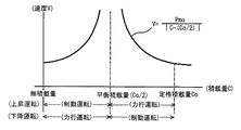
図2は、エレベータの駆動系におけるエネルギーの授受を示す説明用図である。
巻上機6に巻き掛けられて垂下された主索8の一方にかご9が吊持され、他方に釣合錘7が吊持されている。巻上機6は減速機6aを介して巻上電動機10によって駆動される。電源装置29から供給される電力は、インバータ装置28によって可変電圧可変周波数の交流電源に変換されて巻上電動機10を付勢する。
かご9の速度をV(m/s)、かご自重W(N)と積載量C(N)を合算したかご総重量をM(N)、釣合錘重量をm(N)とし、釣合錘重量mは、かご自重Wと定格積載量Co(N)の50%を合算した重量とする。かご9を昇降速度V(m/s)で昇降させるときの昇降エネルギーPm(w)は、Pm=V(M−m)となる。更に、M=(W+C)、m={W+(Co/2)}であるから、Pm=V{C−(Co/2)}となる。
FIG. 2 is an explanatory diagram showing energy transfer in the drive system of the elevator.
A car 9 is suspended on one side of the
The speed of the car 9 is V (m / s), the car total weight W (N) and the load capacity C (N) are added to the total car weight M (N), the counterweight is m (N) The weight m is a weight obtained by adding 50% of the car's own weight W and the rated load capacity Co (N). The lifting energy Pm (w) when raising and lowering the car 9 at the raising / lowering speed V (m / s) is Pm = V (M−m). Further, since M = (W + C) and m = {W + (Co / 2)}, Pm = V {C− (Co / 2)}.
1. 力行運転時
力行運転は、電源装置29から巻上機6にエネルギーが供給される運転である。即ち、電源装置29は、途中の電線におけるエネルギー損失、インバータ装置28、巻上電動機10及び減速機6a等におけるエネルギー損失を併せて供給してかご9側に昇降エネルギーPmを供給する。力行運転時は減速機6aの効率はηとなる。従って、上記電線、インバータ装置28、巻上電動機10及び減速機6a等は、かご9側に定格積載量Coを積載して実定格速度Vafで上昇させる能力を備えている。
かご9の積載量Cが定格積載量Coよりも小さい積載量Cの場合、即ち、かご総重量Mが釣合錘重量mに近付くにつれて、昇降エネルギーPmも定格積載量Co時の昇降エネルギーPmoよりも小さくなる。このため、上記電線、インバータ装置28、巻上電動機10及び減速機6a等に余裕が生じる。
そこで、積載量Cのときは、定格積載量Coのときの昇降エネルギーPmoに等しくなる昇降速度Vまで昇降速度を高めることができる。即ち、
Pmo=V|C−(Co/2)|
∴V=Pmo/|C−(Co/2)| (1)
となる。この関係を図3に表わす。
1. Power running operation Power running operation is an operation in which energy is supplied from the
When the load capacity C of the car 9 is smaller than the rated load capacity Co, that is, as the total car weight M approaches the counterweight m, the lift energy Pm is also higher than the lift energy Pmo at the rated load capacity Co. Becomes smaller. For this reason, a margin arises in the electric wire, the
Therefore, when the load is C, the ascending / descending speed can be increased to the ascending / descending speed V equal to the ascending / descending energy Pmo at the rated load capacity Co. That is,
Pmo = V | C- (Co / 2) |
∴V = Pmo / | C- (Co / 2) | (1)
It becomes. This relationship is shown in FIG.
2. 制動運転時
制動運転は、かご9側から減速機6a、巻上電動機10、インバータ装置28を経由して電源装置29にエネルギーが返還される運転である。このとき、力行運転時と同様に、それぞれの装置で損失が生じる。特に、減速機6aにウオームギャが使用される場合は逆効率γとなり、巻上電動機10及びインバータ装置28に返還される昇降エネルギーPmは小さくなる。従って、定格積載量Coで下降する場合は、巻上電動機10及びインバータ装置28には余裕が生じる。このため、巻上電動機10及びインバータ装置28に限れば、定格積載量Coであっても下降運転時は昇降速度Vを上げることができる。
しかしながら、減速機6aについては、制動運転時も力行運転時と略同程度のエネルギー損失が発生する。このため、制動運転時は、昇降速度Vは減速機6aによって制約を受けることになる。
2. During braking operation The braking operation is an operation in which energy is returned from the car 9 side to the
However, with respect to the
例えば、減速機6aにおけるエネルギー損失の一例として、減速比が67:1の場合について述べる。力行運転時の効率η=0.63に対して、制動運転時の逆効率γ=0.39という計算データがある。力行運転時のかご9側の昇降エネルギーPmに対して、減速機6aにおけるエネルギー損失Lmは、下記の式で表される。即ち、
Lm=(Pm/η)−Pm=Pm(1−η)/η
一方、制動運転時のエネルギー損失Lbは、下記の式で表される。即ち、
Lb=Pm−γPm=Pm(1−γ)
ここで、η=0.63及びγ=0.39を代入すると、Lm=0.59Pm、Lb=0.61Pmとなり、制動運転時の方が若干高いものの両者は略等しくなる。
かご総重量Mが釣合錘重量mに近付くにつれて、昇降エネルギーPmも定格積載量Co時の昇降エネルギーPmoよりも小さくなり、それに応じてエネルギー損失Lm及びLbは、いずれも減少する。エネルギー損失Lm及びLbの減少に伴って、かご9の昇降速度Vを上昇させることができる。この関係は、力行運転時と同じであって、制動運転時についても上記式(1)が成立するものと考えられる。この考えの下に制動運転時の積載量Cと昇降速度Vの関係も図3に併せて示す。
For example, a case where the reduction ratio is 67: 1 will be described as an example of energy loss in the
Lm = (Pm / η) −Pm = Pm (1−η) / η
On the other hand, the energy loss Lb during braking operation is expressed by the following equation. That is,
Lb = Pm−γPm = Pm (1−γ)
Here, when η = 0.63 and γ = 0.39 are substituted, Lm = 0.59 Pm and Lb = 0.61 Pm, which are substantially the same although they are slightly higher during the braking operation.
As the total car weight M approaches the counterweight m, the lifting energy Pm also becomes smaller than the lifting energy Pmo at the rated load capacity Co, and the energy losses Lm and Lb both decrease accordingly. As the energy losses Lm and Lb decrease, the raising / lowering speed V of the car 9 can be increased. This relationship is the same as that during power running, and it is considered that the above formula (1) is also established during braking. Based on this idea, the relationship between the loading capacity C and the lifting speed V during braking operation is also shown in FIG.
なお、昇降速度Vを変動させたときの巻上電動機10について考えると、巻上電動機10の定格時のトルクTo、印加電圧Vo及び電流Io、回転磁界の磁束Φoとすると下記の関係が成立する。
To=Φo・Io
Vo=d(Φo)/dt
かご9の昇降速度Vを上げるために周波数をn倍にすると、印加電圧Voのピーク値は抑えられているので、磁束Φoを(1/n)倍にしなければならない。従って、定格電流Ioを流したときのトルクTnは、
Tn=(Φo/n)・Io=To/n
即ち、昇降速度Vをn倍にするとトルクTnは、定格トルクToの(1/n)倍になる。かご総重量Mが釣合錘重量mに近付くにつれてトルクTも減少して昇降エネルギーPmも減少する。昇降エネルギーPmが減少した分だけ、巻上電動機10の電流を定格電流Ioに保った状態で、昇降速度Vを上げることができる。
Considering the hoisting
To = Φo ・ Io
Vo = d (Φo) / dt
When the frequency is increased n times to increase the raising / lowering speed V of the car 9, the peak value of the applied voltage Vo is suppressed, so that the magnetic flux Φo must be increased (1 / n) times. Therefore, the torque Tn when the rated current Io is passed is
Tn = (Φo / n) · Io = To / n
That is, when the elevating speed V is increased n times, the torque Tn becomes (1 / n) times the rated torque To. As the total car weight M approaches the counterweight m, the torque T decreases and the lifting energy Pm also decreases. The raising / lowering speed V can be increased in the state where the current of the hoisting
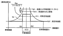
図4は、改修後のエレベータの実速度Vaの最高速度Vmを示す説明用図であって、この最高速度Vmは、図1に示したエレベータの速度の規制要件と、図3に示したインバータ装置28、巻上電動機10及び減速機6a等の能力から規制される要件とから定められる。
まず、図3に示された巻上電動機10及び巻上機6の能力から決められる昇降速度Vを、かご9の実速度Vaの最高速度Vmとする。即ち、定格積載量Coで上昇するときの最高速度Vmを実定格速度Vafとする。従って、既設制御装置で採用されていた実定格速度Vafと同値になる。かご9と釣合錘7が釣り合う平衡積載量Cbは、定格積載量Coの50%であるから、無積載量のときも巻上電動機10に対しては、定格積載量Coと同じ負荷トルクとなり、最高速度Vmも実定格速度Vafに等しくなる。
積載量Cが平衡積載量Cb(=Co/2)に近付くにつれて、図3に示したとおり、最高速度Vmを(1)式で表される曲線に沿って増速させることができる。
FIG. 4 is an explanatory diagram showing the maximum speed Vm of the actual speed Va of the elevator after the refurbishment. The maximum speed Vm is the regulation requirement for the speed of the elevator shown in FIG. 1 and the inverter shown in FIG. It is determined from the requirements regulated by the capabilities of the
First, the lifting speed V determined from the capabilities of the hoisting
As the load capacity C approaches the equilibrium load capacity Cb (= Co / 2), the maximum speed Vm can be increased along the curve represented by the equation (1) as shown in FIG.
図1に示したとおり、改修後のエレベータの呼称定格速度Vrtは実定格速度Vafの111%であり、呼称定格速度Vrtの130%が調速機の過速スイッチの動作速度であるから、この値から動作余裕代Vsmを差し引いた値が実速度Vaの上限値Vattである。積載量Cが積載量Cb1になると、最高速度Vmは上限値Vattに等しくなる。同様に積載量Cb2のときも、最高速度Vmは上限値Vattに等しくなる。平衡積載量Cbを含む積載量Cb1と積載量Cb2の間を平衡積載域とし、この平衡積載域内でのかご9の実速度Vaの最高速度Vmを平衡域速度とする。ここでは平衡域速度を上限値Vattに設定する。 As shown in FIG. 1, the nominal rated speed Vrt of the elevator after the repair is 111% of the actual rated speed Vaf, and 130% of the nominal rated speed Vrt is the operating speed of the overspeed switch of the governor. A value obtained by subtracting the operating margin Vsm from the value is the upper limit value Vatt of the actual speed Va. When the load amount C becomes the load amount Cb1, the maximum speed Vm becomes equal to the upper limit value Vatt. Similarly, at the load amount Cb2, the maximum speed Vm is equal to the upper limit value Vatt. The balance between the load capacity Cb1 and the load capacity Cb2 including the equilibrium load capacity Cb is defined as an equilibrium load area, and the maximum speed Vm of the actual speed Va of the car 9 within this equilibrium load area is defined as the equilibrium area speed. Here, the equilibrium region speed is set to the upper limit value Vatt.
図5は、エレベータの制御装置の全体構成を示すブロック図である。
昇降路1内に収められたかご9には、かご操作盤3が取り付けられており、かご9の行先階を指定するかご呼びが登録される。かご9の積載量Cは秤装置19によって計量される。乗場4には乗場釦20が取り付けられていて、かご9を呼び寄せる乗場呼びが登録される。
FIG. 5 is a block diagram showing the overall configuration of the elevator control apparatus.
A car operation panel 3 is attached to the car 9 housed in the
主索8は昇降路1の頂部に設置された巻上機6に巻き掛けられて垂下され、一方でかご9を吊持し、他方で釣合錘7を吊持している。巻上機6は減速機6aを介して電動機10によって駆動される。電動機軸にはエンコーダ10aが取り付けられていて、角速度、即ち、かご9の速度を検出するようになっている。かご位置演算装置22は、エンコーダ10aからの速度信号を積算して、かご9の現在位置を演算する。
かご呼び又は乗場呼びが登録されると、次回停止階決定装置21は、次に応答すべき呼びが登録された次回停止階を決定する。昇降距離演算装置23は、かご9の現在位置から次回停止階までの昇降距離、即ち残昇降距離Dを演算する。負荷トルク演算装置26は、秤装置19によって計測された積載量Cと運転方向から負荷トルクを演算する。
The
When the car call or the hall call is registered, the next stop
最高速度設定装置24は、かご9の積載量Cに基いて、かご9の実速度Vaの最高速度Vmを設定する。具体的には、図4に示す積載量Cと最高速度Vmとを対応させて配列された積載量・最高速度テーブルになっていて、積載量Cに対応する最高速度Vmを、上記テーブルから読み取って出力する。速度パターン発生装置25は、予め定められた加速度及び減速度と、昇降距離演算装置23からの昇降距離Dと、最高速度設定装置24からの最高速度Vmによって速度パターンを発生させる。インバータ制御装置27は、負荷トルクと速度パターンと速度帰還信号に基いてインバータ装置28を制御する。インバータ装置28は電源29から電力の供給を受けて電動機10を付勢して巻上機6を駆動する。
The maximum
図6は、エレベータの制御装置によって生成される速度パターンの生成手順を示す流れ図である。
手順S11で、乗場呼び又はかご呼びが登録されると、手順S12へ移り、応答すべき呼びに対応する次回停止階が決定されると共に、かご9の運転方向が決定される。手順S13で、かご9の現在位置と次回停止階の位置データに基いて昇降距離Dが演算される。手順S14で、戸閉が完了するのを待って手順S15へ移る。戸閉の完了によってかご9の積載量Cが確定する。手順S15では、確定した積載量Cと運転方向から負荷トルクが演算される。
FIG. 6 is a flowchart showing a procedure for generating a speed pattern generated by the elevator control apparatus.
When the hall call or car call is registered in step S11, the process proceeds to step S12, the next stop floor corresponding to the call to be answered is determined, and the driving direction of the car 9 is determined. In step S13, the lifting distance D is calculated based on the current position of the car 9 and the position data of the next stop floor. In step S14, the process waits for the door closing to be completed and proceeds to step S15. When the door is closed, the loading amount C of the car 9 is determined. In step S15, the load torque is calculated from the determined loading amount C and the driving direction.
手順S16で、積載量Cに対応する最高速度Vmが設定される。具体的には、上記のとおり、図4に示す積載量Cと最高速度Vmとを対応させて配列された積載量・最高速度テーブル24aから最高速度Vmを読み取る。手順S17で、昇降距離Dと最高速度Vmと運転方向に基いて速度パターンが生成される。加速度及び減速度は予め定められており、先ず最高速度Vmに達するための加速距離と減速距離が演算される。手順S13で演算された昇降距離Dが、符号D1で示したとおり短距離であって、加速距離と減速距離の合計値が昇降距離D1を超える場合は、最高速度Vmに達することなく、加速途中で減速させる速度パターンP1が生成される。また、昇降距離Dが、符号D2で示したとおり長距離であって、加速距離と減速距離の合計値よりも昇降距離D2が長い場合は、最高速度Vmに達する速度パターンP2が生成される。いずれの速度パターンも、かご9の始動位置から次回停止階までを細区分し、各位置から次回停止階までの昇降距離Dに対応させて実速度Vaが配列された昇降距離・昇降速度テーブル25aが生成される。 In step S16, the maximum speed Vm corresponding to the load amount C is set. Specifically, as described above, the maximum speed Vm is read from the load quantity / maximum speed table 24a in which the load capacity C and the maximum speed Vm shown in FIG. In step S17, a speed pattern is generated based on the lifting distance D, the maximum speed Vm, and the driving direction. The acceleration and deceleration are determined in advance. First, an acceleration distance and a deceleration distance for reaching the maximum speed Vm are calculated. When the lift distance D calculated in step S13 is a short distance as indicated by reference sign D1 and the total value of the acceleration distance and the deceleration distance exceeds the lift distance D1, the acceleration speed Dm does not reach the maximum speed Vm. A speed pattern P1 to be decelerated is generated. Further, when the ascending / descending distance D is a long distance as indicated by reference sign D2 and the ascending / descending distance D2 is longer than the total value of the acceleration distance and the deceleration distance, a speed pattern P2 reaching the maximum speed Vm is generated. Each speed pattern is subdivided from the starting position of the car 9 to the next stop floor, and a lift distance / lift speed table 25a in which the actual speed Va is arranged corresponding to the lift distance D from each position to the next stop floor. Is generated.
手順S18で起動指令が出されると、手順S19で、次回停止階までの残昇降距離Dが演算される。即ち、手順S12で演算された昇降距離Dから、その時までに昇降した距離が減算される。手順S20で、残昇降距離Dに対応する昇降速度Vが速度パターンに従って設定される。具体的には、残昇降距離Dに対応する実速度Vaを昇降距離・昇降速度テーブル25aから読み取る。読み取られた実速度Vaは、速度指令値としてインバータ制御装置27へ指令される。インバータ制御装置27は上記指令に基いてインバータ装置28を制御する。手順S21で目的階へ到着したか調べる。具体的には、昇降距離・昇降速度テーブル25aにおいて、残昇降距離Dが(D−nd)=0又は所定の着床域内、即ち、一つ手前の{D−(n−1)}若しくは行き過ぎて{D−(n+1)}になった場合は、到着したと見做して実速度Va=0となり、処理を終わる。到着していない場合は、手順S19へ戻って目的階へ到着するまで上記処理が繰り返される。
When a start command is issued in step S18, the remaining lift distance D to the next stop floor is calculated in step S19. That is, the distance that has been raised and lowered up to that time is subtracted from the raising and lowering distance D calculated in step S12. In step S20, the lifting speed V corresponding to the remaining lifting distance D is set according to the speed pattern. Specifically, the actual speed Va corresponding to the remaining lift distance D is read from the lift distance / lift speed table 25a. The read actual speed Va is commanded to the
上記のとおり、実施の形態1によるエレベータの改修方法は、既設のエレベータの既設の巻上機6及びこの巻上機6を駆動する既設の巻上電動機10は継続して使用することとし、巻上電動機10を制御する制御装置を既設制御装置から新設制御装置に取り替えるエレベータの改修方法であって、新設制御装置によるかご9の実定格速度Vafを、既設制御装置による実定格速度Vafと同値となるように巻上電動機10を制御すると共に、改修後のエレベータの呼称定格速度Vrtを、許容範囲内である実定格速度Vafの1.11倍に改変し、かご9の積載量Cが釣合錘7と釣り合う平衡積載量Cbを含む所定の平衡積載域(Cb1〜Cb2)内では、かご9の実速度Vaの最高速度Vmが呼称定格速度Vrtを基準に設定された許容限度である実速度Vaの上限値Vattで巻上電動機10を制御し、かつ、平衡積載域(Cb1〜Cb2)外では、かご9の実速度Vaの最高速度Vmが巻上電動機10の能力から定められる昇降速度V、即ち、(1)式で表される速度Vで巻上電動機10を制御するようにしたものである。
As described above, in the elevator repair method according to the first embodiment, the existing hoisting machine 6 of the existing elevator and the existing hoisting
即ち、平衡積載域(Cb1〜Cb2)内では、最高速度Vmは実速度Vaの上限値Vattとなる。上限値Vattは、調速機の過速スイッチの動作速度から動作余裕代Vsmを差し引いた値であるので、Vatt=1.11×1.3×Vrt−Vsmである。例えば、呼称定格速度Vrtを60m/minとし、動作余裕代Vsmを5m/minとすると、平衡積載域(Cb1〜Cb2)内の最高速度Vmは、約82m/minである。
このため、改修工事によって新設されたエレベータの制御装置によれば、輸送能力が向上し、改修工事の意義を高めることができる。
That is, the maximum speed Vm is the upper limit value Vatt of the actual speed Va in the balanced loading area (Cb1 to Cb2). Since the upper limit value Vatt is a value obtained by subtracting the operating margin Vsm from the operating speed of the overspeed switch of the governor, Vatt = 1.11 × 1.3 × Vrt−Vsm. For example, when the nominal rated speed Vrt is 60 m / min and the operating margin Vsm is 5 m / min, the maximum speed Vm in the balanced loading area (Cb1 to Cb2) is about 82 m / min.
For this reason, according to the elevator control apparatus newly established by the renovation work, the transportation capacity is improved and the significance of the renovation work can be enhanced.
実施の形態2.
この実施の形態2は、実施の形態1で示したエレベータの制御装置の一部を変更した実施例を示す。
実施例1.
図7は、この実施例1におけるエレベータの実速度Vaの最高速度Vmを示す説明用図である。図7より明かなとおり、平衡積載域(Cb1〜Cb2)外における最高速度Vmは、実定格速度Vafとし、平衡積載域(Cb1〜Cb2)内では、呼称定格速度Vrtよりも高く、上限値Vattよりも低い速度に設定した。
このため、エレベータの輸送能力を向上させると共に、巻上電動機10及び減速機6a等は、余裕を持って最高速度Vmで運転を行うことができる。特に、平衡積載域(Cb1〜Cb2)内では、上限値Vattに対しても余裕を持った運転を行わせることができる。
The second embodiment shows an example in which a part of the elevator control device shown in the first embodiment is changed.
Example 1.
FIG. 7 is an explanatory diagram showing the maximum speed Vm of the actual speed Va of the elevator in the first embodiment. As is clear from FIG. 7, the maximum speed Vm outside the balanced loading area (Cb1 to Cb2) is the actual rated speed Vaf, and within the balanced loading area (Cb1 to Cb2), it is higher than the nominal rated speed Vrt, and the upper limit value Vatt. Was set to a lower speed.
For this reason, while improving the transport capability of an elevator, the hoisting
実施例2.
実施の形態1では、エレベータの改修によって新設される制御装置に係るものであった。この実施例2では、新規に設置されるエレベータの制御装置であっても、同様にであって、最高速度Vmを実施の形態1と同様に上げることによって、エレベータの輸送能力の向上を図ることができる。
実施例3.
実施の形態1では、減速機6a付のエレベータについて述べたが、減速機6aを具備しないエレベータであっても同様であって、巻上電動機等の能力から決められる昇降速度Vは、図4に示す特性を有し、積載量Cに対して最高速度Vmを上げることができる。
Example 2
The first embodiment relates to a control device that is newly provided by repairing an elevator. In Example 2, even in a newly installed elevator control device, the same applies, and the elevator transportation capacity is improved by increasing the maximum speed Vm in the same manner as in the first embodiment. Can do.
Example 3
In the first embodiment, the elevator with the
1 昇降路、 4 乗場、 6 巻上機、 6a 減速機、 7 釣合錘、 8 主索、 9 かご、 10 巻上電動機、 10a エンコーダ、 18 かご操作盤、 19 秤装置、 20 乗場釦、 21 次階停止階決定装置、 22 かご位置演算装置、 23 昇降距離演算装置、 24 最高速度設定装置、 24a 積載量・最高速度テーブル、 25 速度パターン発生装置、 25a 昇降距離・昇降速度テーブル、 26 負荷トルク演算装置、 27 インバータ制御装置、 28 インバータ装置、 29 電源装置。 1 hoistway, 4 landing, 6 hoisting machine, 6a reduction gear, 7 counterweight, 8 main rope, 9 car, 10 hoisting motor, 10a encoder, 18 car operating panel, 19 scale device, 20 landing button, 21 Next floor stop floor determination device, 22 car position calculation device, 23 lift distance calculation device, 24 maximum speed setting device, 24a load capacity / maximum speed table, 25 speed pattern generator, 25a lift distance / lift speed table, 26 load torque Arithmetic device, 27 inverter control device, 28 inverter device, 29 power supply device.
Claims (4)
上記制御装置は、上記かごの積載量Cを計測する秤装置19と、上記秤装置によって計測された積載量と運転方向から負荷トルクを演算する負荷トルク演算装置26と、上記かごの積載量Cに基づいて、かごの実速度Vaの最高速度Vmを設定する最高速度設定装置24とを備え、上記かごが上記巻上電動機に駆動されて実際に昇降するときの実速度Vaの内、定格積載量Coで上昇するときの最高速度Vmを上記巻上機又は上記巻上電動機の能力から定められる実定格速度Vafで上記巻上電動機を制御すると共に、定格速度として呼称される呼称定格速度Vrtを上記実定格速度Vafに対して所定の範囲内で高くなるように設定し、上記呼称定格速度Vrtの130%である調速機過速スイッチの動作速度Vgtから動作余裕代Vsmを差し引いた値を実速度Vaの上限値Vatt(Vgt−Vsm)とし、上記かごの積載量Cが上記釣合錘と釣り合う平衡積載量Cb(=Co/2)を含む所定の平衡積載域(Cb1〜Cb2)内では、上記平衡積載域内の実速度Vaの最高速度Vmが上記呼称定格速度Vrtよりも高い実速度Vaの上限値Vatt(Vgt−Vsm)となるように設定して上記巻上電動機を制御し、かつ、上記平衡積載域外では、上記実速度Vaの上記最高速度Vmが上記巻上機又は上記巻上電動機の能力から定められる速度となるように上記巻上電動機を制御するようにしたことを特徴とするエレベータの制御装置。 In a control device for controlling an elevator hoisting machine 6 in which a car 9 is suspended on one side of a main rope 8 and a counterweight 7 is suspended on the other side, and a hoisting motor 10 that drives the hoisting machine,
The control device includes a scale device 19 that measures the load amount C of the car, a load torque calculation device 26 that calculates a load torque from the load amount and operation direction measured by the scale device, and a load amount C of the car. And a maximum speed setting device 24 for setting the maximum speed Vm of the actual speed Va of the car, and the rated load is included in the actual speed Va when the car is actually moved up and down driven by the hoisting motor. The maximum speed Vm when rising by the amount Co is controlled at the actual rated speed Vaf determined from the capacity of the hoisting machine or the hoisting motor, and the nominal rated speed Vrt referred to as the rated speed is set. the set to be higher within a predetermined range with respect Jittei rated speed Vaf, the nominal 130% at a speed governor overspeed operation margin from the operating speed Vgt switches rated speed Vrt Vsm A value obtained by subtracting the upper limit value Vatt the actual speed Va (Vgt-Vsm), the equilibrium loading of payload C of the car is balanced with the counterweight Cb (= Co / 2) given equilibrium loading zone comprising (Cb1 within ~Cb2), the hoist set as the maximum speed Vm of the actual speed Va of the equilibrium loading region is the upper limit value Vatt the actual speed Va higher than the upper Symbol nominal rated speed Vrt (Vgt-Vsm) The motor is controlled and the hoisting motor is controlled so that the maximum speed Vm of the actual speed Va becomes a speed determined by the hoisting machine or the capacity of the hoisting motor outside the balanced loading range. An elevator control device characterized by that.
上記新設制御装置は、上記かごの積載量Cを計測する秤装置19と、上記秤装置によって計測された積載量と運転方向から負荷トルクを演算する負荷トルク演算装置26と、上記かごの積載量Cに基づいて、かごの実速度Vaの最高速度Vmを設定する最高速度設定装置24とを備え、上記新設制御装置によるかごの実定格速度Vafを、上記既設制御装置による上記実定格速度Vafと同値となるように上記巻上電動機を制御すると共に、改修後のエレベータの呼称定格速度Vrtを上記実定格速度Vafよりも所定の範囲内で高くなるように改変し、上記呼称定格速度Vrtの130%である調速機過速スイッチの動作速度Vgtから動作余裕代Vsmを差し引いた値を実速度Vaの上限値Vatt(Vgt−Vsm)とし、上記かごの積載量Cが上記釣合錘と釣り合う平衡積載量Cb(=Co/2)を含む所定の平衡積載域(Cb1〜Cb2)内では、上記かごの上記平衡積載域内の実速度Vaの最高速度Vmが上記呼称定格速度Vrtよりも高い実速度Vaの上限値Vatt(Vgt−Vsm)となるように設定して上記巻上電動機を制御し、かつ、上記平衡積載域外では、上記実速度Vaの上記最高速度Vmが上記巻上機又は上記巻上電動機の能力から定められる速度となるように上記巻上電動機を制御するようにしたことを特徴とするエレベータの改修方法。 In an elevator hoisting machine 6 in which a car 9 is suspended on one side of a main rope 8 and a counterweight 7 is suspended on the other side, and a control device for controlling a hoisting motor 10 that drives the hoisting machine, An elevator renovation method in which at least an existing hoisting machine of an elevator is to be used continuously, and a control device that controls the hoisting motor that drives the hoisting machine is replaced from an existing control device to a new control device. ,
The new control device includes a scale device 19 that measures the load amount C of the car, a load torque calculation device 26 that calculates load torque from the load amount and the operation direction measured by the scale device, and the load amount of the car. A maximum speed setting device 24 for setting the maximum speed Vm of the actual speed Va of the car based on C, and the actual rated speed Vaf of the car by the newly installed control device and the actual rated speed Vaf by the existing control device The hoisting motor is controlled to have the same value, and the nominal rated speed Vrt of the elevator after the modification is modified to be higher than the actual rated speed Vaf within a predetermined range, and the nominal rated speed Vrt of 130 is set. % of overspeed switch governor is a value obtained by subtracting the operating margin Vsm from operating speed Vgt the upper limit value Vatt the actual speed Va (Vgt-Vsm), the car The application amount C equilibrium loading capacity commensurate with the counterweight Cb (= Co / 2) given equilibrium loading zone comprising (Cb1~Cb2) in maximum speed Vm of the actual speed Va of the car of the equilibrium loading region There controls on SL nominal upper limit Vatt (Vgt-Vsm) and set to be in the hoisting motor of the actual speed Va higher than the rated speed Vrt, and, in the equilibrium loading outside, the actual speed Va A method for repairing an elevator, characterized in that the hoisting motor is controlled so that the maximum speed Vm is a speed determined from the capacity of the hoisting machine or the hoisting motor.
Priority Applications (1)
| Application Number | Priority Date | Filing Date | Title |
|---|---|---|---|
| JP2005195426A JP4689374B2 (en) | 2005-07-04 | 2005-07-04 | Elevator control device and elevator repair method |
Applications Claiming Priority (1)
| Application Number | Priority Date | Filing Date | Title |
|---|---|---|---|
| JP2005195426A JP4689374B2 (en) | 2005-07-04 | 2005-07-04 | Elevator control device and elevator repair method |
Publications (3)
| Publication Number | Publication Date |
|---|---|
| JP2007008714A JP2007008714A (en) | 2007-01-18 |
| JP2007008714A5 JP2007008714A5 (en) | 2007-11-29 |
| JP4689374B2 true JP4689374B2 (en) | 2011-05-25 |
Family
ID=37747693
Family Applications (1)
| Application Number | Title | Priority Date | Filing Date |
|---|---|---|---|
| JP2005195426A Active JP4689374B2 (en) | 2005-07-04 | 2005-07-04 | Elevator control device and elevator repair method |
Country Status (1)
| Country | Link |
|---|---|
| JP (1) | JP4689374B2 (en) |
Cited By (1)
| Publication number | Priority date | Publication date | Assignee | Title |
|---|---|---|---|---|
| CN102849548A (en) * | 2012-06-20 | 2013-01-02 | 天津大学 | Elevator speed controller for rated-speed-exceeding running and control method of controller |
Families Citing this family (2)
| Publication number | Priority date | Publication date | Assignee | Title |
|---|---|---|---|---|
| JP5360201B2 (en) * | 2009-04-09 | 2013-12-04 | 三菱電機株式会社 | Elevator governor |
| KR101272393B1 (en) * | 2012-02-10 | 2013-06-07 | 엘에스산전 주식회사 | Apparatus for controlling inverter |
Citations (2)
| Publication number | Priority date | Publication date | Assignee | Title |
|---|---|---|---|---|
| JPS62126887A (en) * | 1985-11-25 | 1987-06-09 | Mitsubishi Electric Corp | Speed controller of wound-rotor induction motor |
| JP2003192246A (en) * | 2001-12-26 | 2003-07-09 | Toshiba Elevator Co Ltd | Speed control device, speed control method, and speed control program for elevator |
-
2005
- 2005-07-04 JP JP2005195426A patent/JP4689374B2/en active Active
Patent Citations (2)
| Publication number | Priority date | Publication date | Assignee | Title |
|---|---|---|---|---|
| JPS62126887A (en) * | 1985-11-25 | 1987-06-09 | Mitsubishi Electric Corp | Speed controller of wound-rotor induction motor |
| JP2003192246A (en) * | 2001-12-26 | 2003-07-09 | Toshiba Elevator Co Ltd | Speed control device, speed control method, and speed control program for elevator |
Cited By (1)
| Publication number | Priority date | Publication date | Assignee | Title |
|---|---|---|---|---|
| CN102849548A (en) * | 2012-06-20 | 2013-01-02 | 天津大学 | Elevator speed controller for rated-speed-exceeding running and control method of controller |
Also Published As
| Publication number | Publication date |
|---|---|
| JP2007008714A (en) | 2007-01-18 |
Similar Documents
| Publication | Publication Date | Title |
|---|---|---|
| CN1066694C (en) | Reserve power system | |
| US9067762B2 (en) | Energy savings with optimized motion profiles | |
| JP5307394B2 (en) | Elevator control device | |
| US20130075199A1 (en) | Method for limiting the loading of an elevator assembly, and an elevator assembly | |
| KR20090094832A (en) | Elevator | |
| KR101171371B1 (en) | Controller for elevator | |
| US8789660B2 (en) | Elevator system using a movement profile | |
| JP4689374B2 (en) | Elevator control device and elevator repair method | |
| EP1731466B1 (en) | Elevator control device | |
| JP5554336B2 (en) | Elevator control device | |
| JP5428900B2 (en) | Elevator speed control device | |
| JP4298649B2 (en) | Elevator control device | |
| JP4419517B2 (en) | Control method of motor for driving lifting machine | |
| JP4864436B2 (en) | Elevator control device | |
| JP7204700B2 (en) | Controller for winding drum type elevator | |
| US7392915B2 (en) | Method for controlling spreader in crane | |
| JP4425716B2 (en) | Elevator control device | |
| CN212769207U (en) | Construction elevator driving system and construction elevator | |
| JP2005145637A (en) | Elevator driving system | |
| KR100695768B1 (en) | Inverter control apparatus for reduction against vibration in elevator and method thereof | |
| KR20070024560A (en) | Control system for elevator | |
| JP2022128144A (en) | Device for controlling winding drum type elevator | |
| JP2021059443A (en) | Control device for winding drum type elevator | |
| JPH04256673A (en) | Method for improving elevator | |
| JPH04277197A (en) | Elevating device incorporating electric counterweight |
Legal Events
| Date | Code | Title | Description |
|---|---|---|---|
| A521 | Request for written amendment filed |
Free format text: JAPANESE INTERMEDIATE CODE: A523 Effective date: 20071011 |
|
| A621 | Written request for application examination |
Free format text: JAPANESE INTERMEDIATE CODE: A621 Effective date: 20071011 |
|
| A977 | Report on retrieval |
Free format text: JAPANESE INTERMEDIATE CODE: A971007 Effective date: 20100702 |
|
| A131 | Notification of reasons for refusal |
Free format text: JAPANESE INTERMEDIATE CODE: A131 Effective date: 20100713 |
|
| A521 | Request for written amendment filed |
Free format text: JAPANESE INTERMEDIATE CODE: A523 Effective date: 20100811 |
|
| TRDD | Decision of grant or rejection written | ||
| A01 | Written decision to grant a patent or to grant a registration (utility model) |
Free format text: JAPANESE INTERMEDIATE CODE: A01 Effective date: 20110215 |
|
| A01 | Written decision to grant a patent or to grant a registration (utility model) |
Free format text: JAPANESE INTERMEDIATE CODE: A01 |
|
| A61 | First payment of annual fees (during grant procedure) |
Free format text: JAPANESE INTERMEDIATE CODE: A61 Effective date: 20110216 |
|
| R150 | Certificate of patent or registration of utility model |
Ref document number: 4689374 Country of ref document: JP Free format text: JAPANESE INTERMEDIATE CODE: R150 Free format text: JAPANESE INTERMEDIATE CODE: R150 |
|
| FPAY | Renewal fee payment (event date is renewal date of database) |
Free format text: PAYMENT UNTIL: 20140225 Year of fee payment: 3 |
|
| R250 | Receipt of annual fees |
Free format text: JAPANESE INTERMEDIATE CODE: R250 |
|
| R250 | Receipt of annual fees |
Free format text: JAPANESE INTERMEDIATE CODE: R250 |
|
| R250 | Receipt of annual fees |
Free format text: JAPANESE INTERMEDIATE CODE: R250 |
|
| R250 | Receipt of annual fees |
Free format text: JAPANESE INTERMEDIATE CODE: R250 |
|
| R250 | Receipt of annual fees |
Free format text: JAPANESE INTERMEDIATE CODE: R250 |
|
| R250 | Receipt of annual fees |
Free format text: JAPANESE INTERMEDIATE CODE: R250 |
|
| S533 | Written request for registration of change of name |
Free format text: JAPANESE INTERMEDIATE CODE: R313533 |
|
| R350 | Written notification of registration of transfer |
Free format text: JAPANESE INTERMEDIATE CODE: R350 |
|
| R250 | Receipt of annual fees |
Free format text: JAPANESE INTERMEDIATE CODE: R250 |