JP4683585B2 - Ink set - Google Patents
Ink set Download PDFInfo
- Publication number
- JP4683585B2 JP4683585B2 JP2000265668A JP2000265668A JP4683585B2 JP 4683585 B2 JP4683585 B2 JP 4683585B2 JP 2000265668 A JP2000265668 A JP 2000265668A JP 2000265668 A JP2000265668 A JP 2000265668A JP 4683585 B2 JP4683585 B2 JP 4683585B2
- Authority
- JP
- Japan
- Prior art keywords
- ink
- black
- color
- recording
- black ink
- Prior art date
- Legal status (The legal status is an assumption and is not a legal conclusion. Google has not performed a legal analysis and makes no representation as to the accuracy of the status listed.)
- Expired - Lifetime
Links
Images


Classifications
-
- C—CHEMISTRY; METALLURGY
- C09—DYES; PAINTS; POLISHES; NATURAL RESINS; ADHESIVES; COMPOSITIONS NOT OTHERWISE PROVIDED FOR; APPLICATIONS OF MATERIALS NOT OTHERWISE PROVIDED FOR
- C09D—COATING COMPOSITIONS, e.g. PAINTS, VARNISHES OR LACQUERS; FILLING PASTES; CHEMICAL PAINT OR INK REMOVERS; INKS; CORRECTING FLUIDS; WOODSTAINS; PASTES OR SOLIDS FOR COLOURING OR PRINTING; USE OF MATERIALS THEREFOR
- C09D11/00—Inks
- C09D11/30—Inkjet printing inks
- C09D11/32—Inkjet printing inks characterised by colouring agents
- C09D11/324—Inkjet printing inks characterised by colouring agents containing carbon black
-
- C—CHEMISTRY; METALLURGY
- C09—DYES; PAINTS; POLISHES; NATURAL RESINS; ADHESIVES; COMPOSITIONS NOT OTHERWISE PROVIDED FOR; APPLICATIONS OF MATERIALS NOT OTHERWISE PROVIDED FOR
- C09D—COATING COMPOSITIONS, e.g. PAINTS, VARNISHES OR LACQUERS; FILLING PASTES; CHEMICAL PAINT OR INK REMOVERS; INKS; CORRECTING FLUIDS; WOODSTAINS; PASTES OR SOLIDS FOR COLOURING OR PRINTING; USE OF MATERIALS THEREFOR
- C09D11/00—Inks
- C09D11/30—Inkjet printing inks
- C09D11/38—Inkjet printing inks characterised by non-macromolecular additives other than solvents, pigments or dyes
-
- C—CHEMISTRY; METALLURGY
- C09—DYES; PAINTS; POLISHES; NATURAL RESINS; ADHESIVES; COMPOSITIONS NOT OTHERWISE PROVIDED FOR; APPLICATIONS OF MATERIALS NOT OTHERWISE PROVIDED FOR
- C09D—COATING COMPOSITIONS, e.g. PAINTS, VARNISHES OR LACQUERS; FILLING PASTES; CHEMICAL PAINT OR INK REMOVERS; INKS; CORRECTING FLUIDS; WOODSTAINS; PASTES OR SOLIDS FOR COLOURING OR PRINTING; USE OF MATERIALS THEREFOR
- C09D11/00—Inks
- C09D11/30—Inkjet printing inks
- C09D11/40—Ink-sets specially adapted for multi-colour inkjet printing
-
- B—PERFORMING OPERATIONS; TRANSPORTING
- B41—PRINTING; LINING MACHINES; TYPEWRITERS; STAMPS
- B41J—TYPEWRITERS; SELECTIVE PRINTING MECHANISMS, i.e. MECHANISMS PRINTING OTHERWISE THAN FROM A FORME; CORRECTION OF TYPOGRAPHICAL ERRORS
- B41J2/00—Typewriters or selective printing mechanisms characterised by the printing or marking process for which they are designed
- B41J2/005—Typewriters or selective printing mechanisms characterised by the printing or marking process for which they are designed characterised by bringing liquid or particles selectively into contact with a printing material
- B41J2/01—Ink jet
- B41J2/21—Ink jet for multi-colour printing
- B41J2/2107—Ink jet for multi-colour printing characterised by the ink properties
-
- B—PERFORMING OPERATIONS; TRANSPORTING
- B41—PRINTING; LINING MACHINES; TYPEWRITERS; STAMPS
- B41M—PRINTING, DUPLICATING, MARKING, OR COPYING PROCESSES; COLOUR PRINTING
- B41M5/00—Duplicating or marking methods; Sheet materials for use therein
- B41M5/0011—Pre-treatment or treatment during printing of the recording material, e.g. heating, irradiating
- B41M5/0017—Application of ink-fixing material, e.g. mordant, precipitating agent, on the substrate prior to printing, e.g. by ink-jet printing, coating or spraying
-
- B—PERFORMING OPERATIONS; TRANSPORTING
- B41—PRINTING; LINING MACHINES; TYPEWRITERS; STAMPS
- B41M—PRINTING, DUPLICATING, MARKING, OR COPYING PROCESSES; COLOUR PRINTING
- B41M5/00—Duplicating or marking methods; Sheet materials for use therein
- B41M5/0023—Digital printing methods characterised by the inks used
-
- B—PERFORMING OPERATIONS; TRANSPORTING
- B41—PRINTING; LINING MACHINES; TYPEWRITERS; STAMPS
- B41M—PRINTING, DUPLICATING, MARKING, OR COPYING PROCESSES; COLOUR PRINTING
- B41M7/00—After-treatment of prints, e.g. heating, irradiating, setting of the ink, protection of the printed stock
- B41M7/0018—After-treatment of prints, e.g. heating, irradiating, setting of the ink, protection of the printed stock using ink-fixing material, e.g. mordant, precipitating agent, after printing, e.g. by ink-jet printing, coating or spraying
Landscapes
- Chemical & Material Sciences (AREA)
- Life Sciences & Earth Sciences (AREA)
- Engineering & Computer Science (AREA)
- Materials Engineering (AREA)
- Wood Science & Technology (AREA)
- Organic Chemistry (AREA)
- Ink Jet Recording Methods And Recording Media Thereof (AREA)
- Inks, Pencil-Leads, Or Crayons (AREA)
- Ink Jet (AREA)
Description
【0001】
【発明の属する技術分野】
本発明は、インクセットに関する。
【0002】
【従来の技術】
インクジェット記録方法は、インクを被記録材上に直接吐出して画像を記録する低騒音、かつノンインパクトな記録方法である。また、この方法は、実施するにあたって複雑な装置を必要としないため、低ランニングコスト、装置の小型化、カラー化等が容易である。
【0003】
したがって、従来からインクジェット記録方法を適用したプリンタ、複写機、ファクシミリ、ワードプロセッサ等の記録装置が実用化されている。またこのようなインクジェット記録技術を利用してブラックインクとカラーインク(例えば、イエローインク、シアンインク、マゼンタインク、レッドインク、グリーンインクおよびブルーインクから選ばれる少なくとも1つのカラーインク)を用いて多色の画像を形成する為のカラーインクジェット記録装置も実用化されている。
【0004】
しかし一方で、インクジェット記録方法には異なる2種のインクが隣接して被記録材に付与された場合、該インク同士がそれらの境界部で混ざり合ってしまい、カラー画像の品位が低下する現象(ブリーディング)が発生するという問題がある。特に、ブラックインクとカラーインクの境界部での混色は画像品位低下への影響が大きいため、様々な解決方法の開発が行なわれている。
【0005】
その代表的な解決方法は、2種のインクが隣接して被記録材に付与された時、少なくともどちらか一方の増粘、あるいは少なくともどちらか一方の色材の凝集または沈殿を生起させ、ブリードを防止させるメカニズムを有するインクセット及び記録方法である。
【0006】
例えば、米国特許第5428383号は1つのインクに沈殿剤(例えば多価金属塩)を含み、他のインク、好ましくはブラックインクに、カルボキシル及び/又はカルボン酸塩の基を有する有機染料の形の着色剤を採用することを開示している。これらのインクを互いに隣り合わせてプリントすると、沈殿剤を有している第1のインクが、カルボキシル及び/又はカルボン酸塩の基を有する着色剤の沈殿を生じさせ、それによって着色剤の他のインクへの移動を防ぎ、2つの隣接するプリント領域間のブリードが低減されることが記載されている。
【0007】
また、米国特許第5976230号には、互いに反応する2種のインクを同一の領域に付与することによってブリードを防止する技術を開示している。
【0008】
【発明が解決しようとする課題】
本発明者らの検討によれば、上記米国特許第5976230号に記載されているように、互いに反応性を有する2種のインクを同一領域に付与する方法によって得られる画像は、その濃度が、単独のインクによる画像のそれよりも上昇することを確認している。本願出願人の出願にかかる特開平6-171208号公報においても、顔料系ブラックインクと塩を含むカラーインクとを記録媒体上の同一地点にインクジェット法で着弾させることで、ブラックインク単独で形成したブラックの画像よりも高い濃度の画像が得られたことを開示している。このような、反応系インクセットを重ねることによって画像濃度が高くなること自体は何ら問題となるものではない。
【0009】
しかしながら、同一ドキュメント内のブラック領域内に、ブラックインクのみで形成した部分とカラーインクとブラックインクとの混合によって形成した部分とが混在した場合、ブラックの画像濃度が互いに異なってしまい、視覚的に違和感のある画像となってしまうことがある。より具体的には、1ドキュメント内にカラーの背景を有さないブラックのキャラクター部分(第1のキャラクター部分)とカラーの背景を有するブラックのキャラクター部分(第2にキャラクター部分)とが存在し、第1のキャラクター部分をブラックインク単独で形成し、第2のキャラクター部分をブリード防止の観点から、上記USP5976230に開示されている方法に従ってブラックインク及び該ブラックインクとの反応性を有するカラーインクとを重ねて形成した場合、第1のキャラクター部分の濃度と第2のキャラクター部分の濃度とが視覚的に明らかに異なり、違和感を生じる場合があった。
【0010】
この解決方法の1つとして、ブラックインクの画像領域すべて、即ち上述の例でいえば、第1のキャラクター部分にもブラックインクと相互反応性を示すカラーインクを打ち込みブラックインクを固定化する処理方法を施すことが考えられるが、この場合はカラーインクの消費量の増加、そして先に打ち込んだカラーインクは通常高い浸透性を有するため、記録媒体上でブラックインクよりも広がり易く、例えば黒のキャラクター部において、当該キャラクターがカラーインクによって縁取られているように視覚的に認識されてしまう場合がある。
【0011】
本発明者らは以上の知見に鑑みて、検討を重ねた結果、ブラックインクのみで形成される画像の濃度を、ブラックインクと該ブラックインクに対して反応性を有するカラーインクとの混合によって得られる画像濃度とほぼ同程度にまで改善することのできる技術を見出し本発明を為すに至った。
【0012】
そこで本発明の目的は、少なくともブラックインクとカラーインクとを含みインクの消費量の増加やブラック文字品位の低下といった問題を生じさせることなく、黒色画像に求められる高い光学濃度、画像品位、画像堅牢性等の種々の性能を満たし、このブラックインクが他の色のインクとの間にブリード、白モヤを生じることがなく、更にブラックインクの画像領域に何らかの処理を加えた場合にも光学濃度変化が小さいインクセットを提供することにある。
【0013】
【課題を解決するための手段】
上記目的は以下の本発明により達成することができる。すなわち、本発明にかかるインクセットは、ブラックインクおよびカラーインクを含むインクセットであって、該ブラックインクは、塩として(M1) 2 SO 4 、CH 3 COO(M1)、Ph−COO(M1)、(M1)NO 3 、(M1)Cl、(M1)Br、(M1)I、(M1) 2 SO 3 および(M1) 2 CO 3 から選ばれる少なくとも一つ(M1はアルカリ金属、アンモニウムまたは有機アンモニウムを表し、Phはフェニル基を表す。)と、水性媒体と、アニオン性基がカーボンブラック表面に直接、若しくは他の原子団を介して結合しているカーボンブラックとを含み、該カラーインクの少なくとも一色は、染料と、Mg 2+ 、Ca 2+ 、Cu 2+ 、Co 2+ 、Ni 2+ 、Fe 2+ 、La 3+ 、Nd 3+ 、Y 3+ およびAl 3+ から選ばれる多価金属陽イオンを有する多価金属塩とを含んでいることを特徴とする。
【0019】
上記した構成を採用することによって、ブラックインクが他の色のインクとの間にブリード、白モヤを生じることがなく、また、ブラックインク単独で形成した黒色画像を、カラーインクとブラックインクとを重畳して形成した黒色画像とほぼ同程度の極めて高い濃度にすることができ、視覚的に均一感のある高品位な画像を得ることができるという効果を奏するものである。
【0020】
これら効果が得られる理由は、記録媒体上に付与されたブラックインクはインク中の塩により固液分離が速やかに生じ、顔料が記録媒体表面に十分な固形分として残るためであり、顔料が記録媒体内部に浸透してしまう従来の塩を含まないブラックインクで形成された画像の光学濃度よりも格段にまた、色材濃度の調整等では再現できない程に上昇する。そして、この塩入りのブラックインク単独で形成された画像の光学濃度は、上記した被記録材上でブラックインクが凝集した場合の画像の光学濃度と目視でほぼ同等の高い光学濃度を示す。
【0021】
さらに、モノトーンを表現するためにブラックインクとカラーインクとを重ねて付与する場合においても、従来の技術では上記と同様の理由で光学濃度差が発生するため、滑らかな階調表現を行うためにはブラックインクとカラーインクとの配合比に制約が有り、設計の自由度低下や滑らかな階調表現自体を損なうといった問題が生じていた。しかし、本発明を採用することにより、ブラックインクが凝集した部分の光学濃度とブラックインクのみで形成された部分の光学濃度をほぼ同等にすることが可能となったため、ブラックインクにカラーインクを添加する割合を調整することで任意の階調表現が得られることとなり、より優れた多階調表現の画像を実現できるという他の効果も得られる。
【0022】
【発明の実施の形態】
本発明の一実施態様にかかるインクセットは、カラーインクとブラックインクとが混合された際に、該ブラックインク中の顔料の分散安定性を不安定化させる染料、および、該ブラックインク中の顔料の分散安定性を不安定化させる添加剤の少なくとも一方を含んでいるカラーインクと塩入りのブラックインクを用いている点に1つの特徴を有する。ここで、ブラックインク中の顔料の分散安定性の不安定化とは、具体的には、該顔料の凝集、沈殿、あるいは該ブラックインクの増粘等である。増粘とは混合前の該ブラックインクと該カラーインクのどちらの粘度よりも両者を混合したインクの粘度が高くなった場合の現象を意味する。
【0023】
(ブラックインクとカラーインクの反応性)
本発明にかかるブラックインクとカラーインクの組成は、ブラックインクとカラーインクとが混合されたときに上記したようにブラックインク中の顔料の分散安定性を不安定化させるように各々が調製されることが好ましい。具体的には、
例えば
(1)カラーインクがブラックインクと混合されたときに該ブラックインク中の顔料の分散安定性を不安定化させる染料を含んでいる態様、
(2)カラーインクが、ブラックインクと混合されたときに該ブラックインク中の顔料の分散安定性を不安定化させる添加剤とを含んでいる態様、等が挙げられる。
【0024】
上記(1)の態様をより詳細に述べれば、例えば以下のi)やii)が挙げられる。
【0025】
i)ブラックインク中の顔料がアニオン性基を有し、カラーインクの染料がカチオン性基を有する様に調製する例。
【0026】
この例においては、カラーインクとブラックインクとが混合されると、カラーインクの染料のカチオン性基がブラックインク中の顔料のアニオン性基と反応し、ブラックインク中の顔料が分散破壊を起こし、顔料を凝集させ、またインクを増粘させる。
【0027】
ii)ブラックインク中の顔料がカチオン性基を有し、カラーインク中の染料がアニオン性基を有する様に調製する例。
【0028】
この例においては、カラーインクとブラックインクとが混合されると、カラーインク中の染料のアニオン性基がブラックインク中の顔料のカチオン性基と反応し、その結果ブラックインク中の顔料が分散破壊を起こし、顔料が凝集し、またインクを増粘させる。
【0029】
上記(2)の態様をより詳細に述べれば、例えば以下のiii)〜v)が挙げられる。
【0030】
iii)ブラックインク中の顔料がアニオン性基を有し、 カラーインクが多価金属陽イオンからなる多価金属塩、例えば、Mg2+、Ca2+、Cu2+、Co2+、Ni2+、Fe2+、La3+、Nd3+、Y3+およびAl3+から選ばれる多価金属陽イオンからなる少なくとも一つの多価金属塩を有する様に調製する例。
【0031】
この例においては、カラーインクとラックインクとが混合されると、カラーインク中の多価金属塩の多価金属陽イオンがブラックインク中の顔料のアニオン性基と反応し、その結果ブラックインク中の顔料が分散破壊を起こし、顔料を凝集させ、またインクを増粘させる。ここでカラーインクに含有させる多価金属塩としては、カラーインクの全質量に対して例えば、約0.1〜15質量%を含有させることが好ましい。
【0032】
iv)ブラックインク中の顔料がpHの3〜7において安定に分散されていて、カラーインクがpH8〜11となる様に調製する例。
【0033】
この例においては、カラーインクとブラックインクが混合されると、ブラックインクのpHが上昇することにより、顔料の分散安定性が破壊され、顔料が凝集し、インクが増粘する。
【0034】
v)ブラックインク中の顔料がpHの7〜11において安定に分散されていて、カラーインクがpH3〜6となる様に調製する例。
【0035】
この例においては、カラーインクとブラックインクが混合されると、ブラックインクのpHが低下することにより、顔料の分散安定性が破壊され、顔料が凝集し、インクを増粘させる。
【0036】
そしてかかるインクセットを用いることで、ブラックインク単独で形成された画像と、ブリード、白モヤの緩和のためにブラックインクとカラーインクとの重畳によって形成された画像との画像濃度の差を目視では殆ど認識し得ない程度にまで小さくすることができる、という効果を得られる。本発明においては、上記i)の態様が用いられる。
【0037】
このような効果が得られる理由について、以下にその理由を説明する。
【0038】
(ブラックインクとカラーインクとで形成される画像)
まず、ブリード、白モヤの緩和のために、顔料ブラックインクと該ブラックインク中の顔料の分散安定性を不安定化させる染料もしくは添加剤を含むカラーインクとを重畳することによって高い濃度の画像が得られる理由を説明する。
【0039】
ブラックインクおよびカラーインクを用いてブリード、白モヤの緩和のための処理を行なう場合、インクの付与順が異なる以下の2通りの方法が考えられる。
【0040】
まず、カラーインクが付与された後、ブラックインクを付与する方法によって被記録材上で生じている現象を図9(d)〜(f)に示す。図9(d)〜(f)は塩の入っているブラックインク、及びブラックインクと反応性を示すカラーインク、具体的には例えばブラックインク中の顔料の分散安定性を不安定化させる染料を含むカラーインクを用いた場合において、該ブラックインクと該カラーインクが同じ場所に付与された様子を示している。
【0041】
カラーインク 1305 によって浸透性の高くなった記録媒体 1303 面上にブラックインク 1301 が付与されるため、ブラックインク 1301 の記録媒体内部への浸透は早くなる。しかし、ブラックインク 1301 中に含有されてなる塩の効果によって、ブラックインクの顔料の記録媒体内部への浸透よりも、ブラックインクの記録媒体表面における固液分離が早く起こり、顔料の分離、固化が速く行われる。更にブラックインク 1301 中の顔料は記録媒体 1303 の表面でカラーインク 1305 と接触することで、水性溶媒中における分散状態の不安定化とそれに伴う凝集が生じ、凝集物 1309 が記録媒体の表面に析出し、図9(f)のようにインク中の色材の浸透が抑えられる。
【0042】
ここで、カラーインク中の、顔料の分散安定性を不安定化させる成分がカラーインク中の色材そのものである場合(上記(1)の態様)、カラーインクの高い浸透性によって本来であれば、記録媒体の内部に浸透してしまう染料も、凝集物の形成に関与することとなる。一方、顔料の分散安定性の不安定化成分が添加剤、例えば二価金属塩であるような場合(上記(2)の場合)には、カラーインク中の染料は記録媒体の内部に浸透し、顔料凝集物の形成には殆ど関与しないが、顔料の分散安定性を不安定化させる二価金属塩により、多くの凝集体が生じ記録媒体の表面近傍に残留すると考えられる。また上記(1)及び(2)のいずれの場合においても、反応に関与しなかった顔料は、凝集物 1309 の上に乗った形になり、画像濃度の向上に寄与しているものと考えられる。
【0043】
このように、いずれの場合であっても、画像濃度を決定すると考えられている記録媒体表面上並びに記録媒体表面から約15〜30μmの深さの範囲内における色材の占有率は、非常に高いものとなり、高い画像濃度が達成されることになる。
【0044】
次に、ブラックインクが付与された後にカラーインクが付与された場合について図9(a)〜(c)に示す。浸透性の低いブラックインクが図9(a)のように記録媒体を覆うと、ブラックインク 1301 は記録媒体 1303 に対して浸透性が低いために遅い速度で浸透していく。そして、その後図9(b)のように浸透性の高いカラーインク 1305 が付与されても記録媒体の表面はブラックインク 1301 で覆われているため、浸透性はあまり変わらない。
【0045】
このような状況においては、ブラックインク 1301、カラーインク 1305 の記録媒体 1303 への浸透は遅いため、図9(c)のようにブラックインク 1301 の色材は記録媒体の表面に残りやすく、高い光学濃度を示す。更にまたブラックインクとカラーインクは反応することにより、ブラックインク中の顔料の凝集物 1309 が紙面上に多く残る。これにより、高い光学濃度の印刷物を得ることができる。また、カラーインクの付与量が多い場合においてもブラックインク中の塩の作用とブラックインクとカラーインクの反応とに基づく、ブラックインクの迅速な固液分離と凝集の現象の両方により紙面上に十分な固形分がのこり、均一感もよい状態である。
【0046】
このように、カラーインクがブラックインクの後に付与された場合、凝集物 1309 の上にカラーインク中の染料が乗った形となる。しかし、インクジェット用インク中の色材の濃度はそれほど高くはない為、例えばカラーインク中の染料濃度がカラーインクの質量の10質量%以下であれば、画像の濃度への寄与は少なくとも目視上では、殆ど寄与はないと考えられる。そして凝集物 1309 が、被記録材表面上および被記録材表面から15〜30μmの範囲内の色材の占有率を飛躍的に向上させる結果、高い濃度の画像が形成されることになる。尚、上記(2)の場合、即ち凝集体の形成に染料が関与しない場合、カラーインク中の染料の中には凝集物1309を通り抜けて記録媒体中に浸透するものもあると思われる。
【0047】
そしてここで用いたインクセットによれば、ブラックインク及びカラーインクの付与順に関わらず、上記の両方法で形成された画像は少なくとも視覚上は、ほぼ等しい、そして高い画像濃度を示す。また、被記録材の上方に凝集物としてインク中の色材が定着されるため、ブラックインクとカラーインクとが被記録材上で重畳されても、高い浸透性を有するカラーインクが顔料を被記録材内部に浸透させることを抑制できる。
【0048】
その結果としてブリードや白モヤの発生を有効に緩和することができる。更に、モノトーンの画像を形成する場合においても、インクの付与順を考慮する必要がなく、より優れた階調表現をより容易に実現することができるのである。
【0049】
(ブラックインク単独で形成される画像)
次に本発明にかかるブラックインクが、上記したブラックインクとカラーインクとの重畳によって得られる画像の濃度と視覚的に殆ど遜色のない濃度の画像が得られるメカニズムは以下のとおりであると考えられる。
【0050】
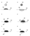
図7(a)〜(c)および図8(a)〜(c)は各々、本発明にかかる塩を含むインクおよび対照としての塩を含まないインクの各々をインクジェット記録法によってオリフィスから吐出させ、普通紙等の浸透性の比較的高い記録媒体に付与したときに、そこで生じる固液分離の様子を模式的、概念的に示した説明図である。即ちインクが着弾した直後には、双方のインク共に図7(a)および図8(a)に示すように塩の添加の有無に関わらず顔料インク 901 または 1001 が紙(903 または 1003)の表面に乗った状態である。
【0051】
時間T1経過後、塩を添加した顔料インクは、図7(b)に示すように、固液分離が速やかに起こり、インク中の固体成分の殆どが豊富に含まれる領域 905 とインク中の溶媒とが分離し、分離した溶剤の浸透先端 907 が溶剤紙 903 内部へと進んでいく。一方、塩を添加しない顔料インクは、図8(b)に示すように、塩を添加したインク程には固液分離が速やかに起こらないために、固液分離しない状態 1005 で、紙 1003 内部へと浸透していく。
【0052】
時間T2経過後:塩を添加した顔料インクは図7(c)に示すように、溶剤の浸透先端 907 は更に紙内部へと浸透していくが、領域 905 は紙の表面とその近傍に留まったままで維持される。一方、塩を添加していない顔料インクは、図8(c)に示すように、この時点において漸く固液分離が始まり、インク中の固形分の浸透先端 1009 と溶媒の浸透先端 1007 との間に差が生じて来るものの、インク中の固形分含有領域 1005 は記録媒体の深部にまで到達している。
【0053】
なお上記説明における時間T1およびT2は、塩の有無による固液分離の相違を概念的に捉えるための目安の時間である。
【0054】
以上から明らかなように、塩を添加することで、固液分離が速やかに起こるために着弾後、比較的速い段階で固液分離とともに、溶液は被記録材内部へと浸透し、顔料は被記録材の上方に留まりやすくなるため、光学濃度が上昇すると考えられる。そして前記したように、ブラックインクは、カラーインクと比較して高い表面張力に設定されるのが一般的であり、ブラックインクの記録媒体への浸透性を高めるようなカラーインクとの重畳のない状態においては、本発明にかかるブラックインクが記録媒体上で、その速い固液分離によって、画像濃度を実質的に規定する記録媒体の表面上ならびに記録媒体の表面から約15〜30μmの深さの領域における顔料の占有率が大幅に向上する。その結果として当該ブラックインク単独で形成された画像の濃度の大幅な向上が図られるものである。
【0055】
図10は、本発明にかかるインクセットを用いたことによる濃度差の緩和効果を示したものである、図10において、ブラックの画像濃度aは、ブラックインクとカラーインクの重畳による画像の濃度であり、bは、本発明にかかる塩を含むブラックインク単独で形成した画像の濃度であり、cは上記の対照に用いた塩を含まないブラックインク単独で形成した画像の濃度である。この図からも分かるように、ブラックインクの画像濃度aとcの間の差が、本発明にかかるインクセットを用いることで、大幅に緩和され、目視での観察では画像濃度aとbの差は殆ど認識し得ない程度のものとすることができる。
【0056】
次に本発明にかかるインクセットを構成するブラックインクならびにカラーインクについて詳細に説明する。
【0057】
(ブラックインクについて)
ブラックインク中の顔料としては例えばカーボンブラックが好適に用いられる。そしてカーボンブラックのインク中での分散の形態としては、自己分散型であっても、分散剤による分散の形態であってもよい。
【0058】
(自己分散型カーボンブラック)
自己分散型のカーボンブラックとしては例えば、少なくとも1つの親水性基(アニオン性基やカチオン性基)がイオン性基としてカーボンブラック表面に直接、若しくは他の原子団を介して結合しているカーボンブラックが挙げられる。これを用いることによって、カーボンブラックを分散させるための分散剤の添加が削減あるいは不要となる。
【0059】
アニオン性基を表面に直接もしくは他の原子団を介して結合しているカーボンブラックの場合、表面に結合されている親水性基の例として、例えば、-COO(M2)、-SO3(M2)、-PO3H(M2)、-PO3(M2)2等を挙げることができる。なお上記式中、「M2」は水素原子、アルカリ金属、アンモニウム又は有機アンモニウムを表わす。これらの中で特に、-COO(M2)、-SO3(M2)がカーボンブラック表面に結合してアニオン性に帯電せしめた自己分散型カーボンブラックは、インク中での分散性が良好な為、本実施態様において特に好適に用い得るものである。
【0060】
ところで上記親水性基中、「M2」として表わしたもののうち、アルカリ金属の具体例としては、例えばLi、Na、K、RbおよびCs等が挙げられ、また有機アンモニウムの具体例としては例えばメチルアンモニウム、ジメチルアンモニウム、トリメチルアンモニウム、エチルアンモニウム、ジエチルアンモニウム、トリエチルアンモニウム、メタノールアンモニウム、ジメタノールアンモニウム、トリメタノールアンモニウム等が挙げられる。
【0061】
そしてM2をアンモニウム或いは有機アンモニウムとした自己分散型カーボンブラックを含む本発明にかかるブラックインクは、記録画像の耐水性をより向上させることができ、この点において特に好適に用いることのできるものである。これは当該インクが記録媒体上に付与されると、アンモニウムが分解し、アンモニアが蒸発する影響によるものと考えられる。ここでM2をアンモニウムとした自己分散型カーボンブラックの製造方法としては、例えばM2がアルカリ金属である自己分散型カーボンブラックをイオン交換法を用いてM2をアンモニウムに置換する方法や酸を加えてH型とした後に水酸化アンモニウムを添加してM2をアンモニウムにする方法等が挙げられる。
【0062】
アニオン性に帯電している自己分散型カーボンブラックの製造方法としては、例えばカーボンブラックを次亜塩素酸ソーダで酸化処理する方法が挙げられ、この方法によってカーボンブラック表面に-COONa基を化学結合させることができる。
【0070】
ところで上記した様な種々の親水性基は、カーボンブラックの表面に直接結合させてもよい。或いは他の原子団をカーボンブラック表面と該親水性基との間に介在させ、該親水性基をカーボンブラック表面に間接的に結合させても良い。ここで他の原子団の具体例としては例えば炭素原子数1〜12の直鎖状若しくは分岐鎖状のアルキレン基、置換もしくは未置換のフェニレン基、置換もしくは未置換のナフチレン基が挙げられる。ここでフェニレン基およびナフチレン基の置換基としては例えば炭素数1〜6の直鎖状または分岐鎖状のアルキル基が挙げられる。また他の原子団と親水性基の組合わせの具体例としては、例えば-C2H4COO(M2)、-Ph-SO3(M2)、-Ph-COO(M2)等(但し、Phはフェニル基を表す)が挙げられる。
【0071】
ところで本発明にかかるブラックインクにおいて上記した自己分散型カーボンブラックの中から2種若しくはそれ以上を適宜選択してインクの顔料に用いてもよい。またインク中の自己分散型カーボンブラックの添加量としてはインク全質量に対して、0.1〜15質量%、特には1〜10質量%の範囲とすることが好ましい。この範囲とすることで自己分散型カーボンブラックはインク中で十分な分散状態を維持することができる。更にインクの色調の調製等を目的として、自己分散型カーボンブラックに加えて染料を色材として添加してもよい。
【0072】
(通常のカーボンブラック)
またブラックインク用の顔料としては、自己分散型でない、通常のカーボンブラックを用いることもできる。
【0073】
このようなカーボンブラックとしては例えば、ファーネスブラック、ランプブラック、アセチレンブラック、チャンネルブラック等のカーボンブラック顔料で、例えば、レイヴァン(Raven)7000、レイヴァン5750、レイヴァン5250、レイヴァン5000ULTRA-、レイヴァン3500、レイヴァン2000、レイヴァン1500、レイヴァン1250、レイヴァン1200、レイヴァン1190ULTRA-II、レイヴァン1170、レイヴァン1255(以上コロンビア社製)、ブラックパールズ(Black Pearls)L、リーガル(Regal)400R、リーガル330R、リーガル660R、モウグル(Mogul)L、モナク(Monarch)700、モナク800、モナク880、モナク900、モナク1000、モナク1100、モナク1300、モナク1400、ヴァルカン(Valcan)XC-72R(以上キャボット社製)、カラーブラック(Color Black)FW1、カラーブラックFW2、カラーブラックFW2V、カラーブラックFW18、カラーブラックFW200、カラーブラックS150、カラーブラックS160、カラーブラックS170、プリンテックス(Printex)35、プリンテックスU、プリンテックスV、プリンテックス140U、プリンテックス140V、スペシャルブラック(Special Black)6、スペシャルブラック5、スペシャルブラック4A、スペシャルブラック4(以上デグッサ社製)、No.25、No.33、No.40、No.47、No.52、No.900、No.2300、MCF-88、MA600、MA7、MA8、MA100(以上三菱化学社製)等を使用することができるが、これらに限定されるものではなく従来公知のカーボンブラックを使用することが可能である。
【0074】
また、マグネタイト、フェライト等の磁性体微粒子やチタンブラック等を黒色顔料として用いても良い。
【0075】
そしてこのような通常型のカーボンブラックをブラックインクの顔料として用いる場合には、これを水性媒体に安定して分散させるために分散剤をインク中に添加することが好ましい。
【0076】
分散剤としては例えばイオン性基を有し、その作用によってカーボンブラックを水性媒体に安定に分散させることのできるものが好適に用いられ、そのような分散剤としては、例えば分散剤として具体的には、スチレン-アクリル酸共重合体、スチレン-アクリル酸-アクリル酸アルキルエステル共重合体、スチレン-マレイン酸共重合体、スチレン-マレイン酸-アクリル酸アルキルエステル共重合体、スチレン-メタクリル酸共重合体、スチレン-メタクリル酸-アクリル酸アルキルエステル共重合体、スチレン-マレイン酸ハーフエステル共重合体、ビニルナフタレン-アクリル酸共重合体、ビニルナフタレン-マレイン酸共重合体、スチレン-無水マレイン酸-マレイン酸ハーフエステル共重合体、あるいは、これらの塩等が挙げられる。この中で質量平均分子量が 1000 から 30000 の範囲のものが好ましく、更に好ましくは 3000 から 15000 の範囲である。
【0077】
(ブラックインクの有する塩について)
本発明にかかるブラックインクの有する塩としては、(M1)2SO4、CH3COO(M1)、Ph-COO(M1)、(M1)NO3、(M1)Cl、(M1)Br、(M1)I、(M1)2SO3および(M1)2CO3から選ばれる少なくとも一つを用いることが好ましい。ここでM1はアルカリ金属、アンモニウムまたは有機アンモニウムを表し、Phはフェニル基を表す。
【0078】
そしてアルカリ金属の具体例としては例えばLi、Na、K、Rb、Cs等が挙げられ、また有機アンモニウムの具体例としては例えばメチルアンモニウム、ジメチルアンモニウム、トリメチルアンモニウム、エチルアンモニウム、ジエチルアンモニウム、トリエチルアンモニウム、トリメタノールアンモニウム、ジメタノールアンモニウム、トリメタノールアンモニウム、エタノールアンモニウム、ジエタノールアンモニウムおよびトリエタノールアンモニウム等が挙げられる。
【0079】
そして上記した塩の中でも硫酸塩(例えば硫酸カリウム等)、安息香酸塩(例えば安息香酸アンモニウム)は自己分散型カーボンブラックとの相性が良く、具体的には記録媒体に付与したときの固液分離効果が特に優れるためか、種々の記録媒体に特に優れた品質のインクジェット記録画像を形成することができる。
【0080】
イオン性基の作用によって水性媒体中に分散させられている顔料を含むインク、例えば自己分散型カーボンブラックを含むインク中に上記したような塩を共存させることによって、記録媒体の種類によって画像品質が大きく変化することのない、安定的に高品位の画像を形成することのできるインクを得ることができる。
【0081】
本発明にかかるブラックインクが上記した様な特性を発揮する詳細なメカニズムは現時点においては明らかでない。しかし、インクの記録媒体への浸透性を表わす尺度として知られているブリストウ法によって求められるKa値に関して、本発明にかかるブラックインクは、塩を添加しない以外は同一の組成を有するインクと比較して大きなKa値を示すとの知見を本発明者らは得ている。
【0082】
Ka値の増加は、インクの記録媒体への浸透性の向上したことを示すものであり、これまでの当業者の常識としてインクの浸透性の向上は、光学濃度の低下を意味するものであった。即ちインクの浸透と共に色材も記録媒体内部に浸透してしまう結果として光学濃度が低下してしまうというのがこれまでの当業者の認識である。
【0083】
そしてこのような本発明にかかるブラックインクに関する種々の知見から総合的に判断すると、該ブラックインク中の塩は、紙面上に付与した後のインク中の溶剤と固形分との分離(固液分離)を極めて速やかに引き起こすという特異的な作用を生じさせていると考えられる。つまりインクが記録媒体に付与されたときの、固液分離が遅ければ、Kaの値の大きいインク、あるいはインクの浸透性の大きな紙上ではインクは色材とともに等方的に紙中に拡散し、その結果文字のシャープネス(文字品位)が損なわれると同時に紙の奥まで色材が浸透するために光学濃度も低下することが予測される。
【0084】
しかし本発明にかかるブラックインクはその様な現象が観察されないことから、記録媒体に付与されたときの固液分離が速やかに起こり、その結果、インクのKa値の増加にも関わらず、高品異な画像を与えるものと推察される。また浸透性が比較的高い紙であっても本発明にかかるブラックインクの場合には、文字品位の低下や光学濃度の低下といった現象は起こりづらい理由もこれと同じと考えられる。
【0085】
本発明にかかるブラックインク中の顔料、例えば自己分散型カーボンブラックの含有量としては、インク全質量に対して、0.1〜15質量%、特には1〜10質量%の範囲とすることが好ましい。また塩の含有量としてはインク全質量に対して0.05〜10質量%、特には0.1〜5質量%の範囲とすることが好ましい。ブラックインク中の顔料および塩の含有量を上記の範囲とすることでより一層優れた効果を享受できる。
【0086】
顔料として前記した自己分散型カーボンブラックを用いるときに、カーボンブラックの表面の親水性基として例えば-COO(M2)、-SO3(M2)2、-PO3H(M2)、-PO3(M2)2を用いる場合、M2としてアンモニウムや有機アンモニウムが好適に用い得ることは上記した通りであるが、このときにブラックインク中の塩として、例えば「M2」と一致させること、即ち「M1」=「M2」とすることは好ましい態様の一つである。
【0087】
即ち本発明者らは自己分散型カーボンブラックを含むインクに対して塩を加えることの効果の検討過程において、自己分散型カーボンブラックの親水性基のM2(カウンターイオン)とM1とを同一としたときに、インクの安定性が特に向上するという知見を得た。M1とM2とを揃えることでこのような効果が得られる理由は明らかではないが、インク中において、自己分散型カーボンブラックの親水性基のカウンターイオンと塩との間で塩交換が生じないため、自己分散型カーボンブラックの分散安定性が安定して維持されるためと推測される。
【0088】
そしてM1とM2との双方をアンモニウム或いは有機アンモニウムとした場合にはインク特性の安定化効果に加えて、記録画像の耐水性のより一層の向上を図ることができる。またこのときインク中の塩としてPh-COO(NH4)(安息香酸アンモニウム)を用いると、インクジェット記録を一時休止させたあとのヘッドノズルからのインクの再吐出性においても極めて優れた結果を得ることができる。
【0089】
(ブラックインクにおける水性媒体)
本発明に係るブラックインクに用いられる水性媒体の例としては例えば水、或いは水と水溶性有機溶剤との混合溶媒が挙げられる。水溶性有機溶媒としては、インクの乾燥防止効果を有するものが特に好ましい。
【0090】
具体的には例えば、メチルアルコール、エチルアルコール、nープロピルアルコール、イソプロピルアルコール、n-ブチルアルコール、sec-ブチルアルコール、tert-ブチルアルコール等の炭素数1〜4のアルキルアルコール類;ジメチルホルムアミド、ジメチルアセトアミド等のアミド類;アセトン、ジアセトンアルコール等のケトンまたはケトアルコール類;テトラヒドロフラン、ジオキサン等のエーテル類;ポリエチレングリコール、ポリプロピレングリコール等のポリアルキレングリコール類;エチレングリコール、プロピレングリコール、ブチレングリコール、トリエチレングリコール、1,2,6-ヘキサントリオ-ル、チオジグリコール、ヘキシレングリコール、ジエチレングリコール等のアルキレン基が2〜6個の炭素原子を含むアルキレングリコール類;ポリエチレングリコールモノメチルエーテルアセテート等の低級アルキルエーテルアセテート;グリセリン;エチレングリコールモノメチル(又はエチル)エーテル、ジエチレングリコールメチル(又はエチル)エーテル、トリエチレングリコールモノメチル(又はエチル)エーテル等の多価アルコールの低級アルキルエーテル類;トリメチロールプロパン、トリメチロールエタン等の多価アルコール;N-メチル-2-ピロリドン、2-ピロリドン、1,3-ジメチル-2-イミダゾリジノン等が挙げられる。上記のごとき水溶性有機溶剤は、単独でもあるいは混合物としても使用することができる。水としては脱イオン水を使用することが望ましい。
【0091】
本発明にかかるブラックインク中に含有される水溶性有機溶剤の含有量は特に限定されないが、インク全質量に対して、好ましくは3〜50質量%の範囲が好適である。又、インクに含有される水の含有量はインク全質量に対して好ましくは50〜95質量%の範囲である。
【0092】
以上説明してきたブラックインクは、印刷品質の記録媒体特性への依存性を極めて低減させることができるという優れた効果を奏するものである。そして本発明にかかるブラックインクの優れた点はこればかりではない。
【0093】
即ち、該ブラックインクと、対照として塩を含まない以外は同一の組成のブラックインクとに関して、顔料濃度と各々のインクによる画像の光学濃度との関係をプロットしたグラフを図11に示す。図11から分かる様に、いずれのインクによる画像の光学濃度も最終的には同程度の値に到達するが、本発明にかかるブラックインク(a)は、対照のブラックインク(b)よりも低い顔料濃度で飽和値に到達するとの知見を得た。即ち塩の添加によって、画像の光学濃度に変化を与えることなく、インク中の顔料濃度を減らすことが可能となるのである。
【0094】
具体的には例えば塩として安息香酸アンモニウムを1質量%程度含ませた場合、自己分散型カーボンブラックの濃度を約4質量%とすることで、普通紙上の印刷の光学濃度は例えば1.4程度にまで達し、カーボンブラック濃度をこれ以上増しても光学濃度はあまり変化しない。これに対して塩を含まないインクはカーボンブラック濃度4質量%とした場合には普通紙上の印刷の光学濃度は1.32程度であり、カーボンブラック濃度7質量%とした場合で光学濃度1.35程度となり、そして8質量%とした場合でも1.35程度であって、この値がほぼ飽和値となる。
【0095】
この様な光学濃度の飽和値(1.4と1.35)の差は数値上はわずかに0.05であっても、各々の印刷物を対比するとその差を目視にて明らかに認識することができるものである。この様に塩を加えたインクは、塩を含まないインクと比較して低いカーボンブラック濃度でも高い光学濃度の印刷を行うことができ、且つ光学濃度の飽和値自体も高いという好ましい結果をもたらすものである。尚ここでは自己分散型カーボンを用いた具体例を述べたが、分散剤を用いてカーボンブラックを分散させたブラックインクについても同様の事象が観察された。
【0096】
またこのことは次のようなメリットももたらす。即ち、塩を含むインクは上記した様に印刷物の光学濃度に対するカーボンブラック濃度のマージンが広いという特性を有する。そのため、例えば吸収体を有するインクタンクにこのインクを充填し、そのインクタンクを長期間、同一の姿勢で放置(例えば6ヶ月間ノズルを上にして放置)した後にそのインクタンクを用いて印字を行ったときに、印字初期に得られる印刷物と、インクタンク内のインクを使い切る直前に得られる印刷物との間で目視で確認できるような光学濃度の差を生じさせることを極めて有効に防ぐことができる。
【0097】
上記インクは、塩を添加したことの更に他の効果として、間欠吐出性に優れているという点が挙げられる。間欠吐出性とは記録ヘッドの所定のノズルに着目し、そのノズルからインクを吐出し、その後インクの予備吐出やノズル内のインクの吸引を行う事無しに所定の時間放置し、再びそのノズルからインクを吐出したときに、再吐出の最初から正常にインクが吐出するか否かを評価するものである。
【0098】
(インク特性;インクジェット吐出特性、記録媒体への浸透性について)
本発明にかかるブラックインクは、筆記具用インクやインクジェット記録用インクに用いる事ができる。インクジェット記録方法としては、インクに力学的エネルギーを作用させ、液滴を吐出する記録方法、およびインクに熱エネルギーを加えてインクの発泡により液滴を吐出する記録方法があり、それらの記録方法に本発明のインクは特に好適である。
【0099】
ところで本発明にかかるブラックインクをインクジェット記録用に用いる場合には、該インクはインクジェットヘッドから吐出可能である特性を有する事が好ましい。インクジェットヘッドからの吐出性という観点からは、該液体の特性としては、例えばその粘度を1〜15mPa・s、表面張力が25mN/m以上、特には粘度を1〜5mPa・s、表面張力が25〜50mN/mとする事が好ましい。
【0100】
またインクの記録媒体への浸透性を表わす尺度として、ブリストウ法によって求められるKa値がある。即ち、インクの浸透性を1m2あたりのインク量Vで表わすと、インク滴を吐出してから所定時間tが経過した後におけるインクの記録媒体への浸透量V(mL/m2=μm)は、下記に示すブリストウの式によって示される。
【0101】
V=Vr+Ka(t-tw)1/2
ここでインク滴が記録媒体表面に付着した直後には、インクは記録媒体表面の凹凸部分(記録媒体の表面の荒さの部分)において吸収されるのが殆どで、記録媒体内部へは殆ど浸透していない。その間の時間がコンタクトタイム(tw)、コンタクトタイムに記録媒体の凹凸部に吸収されたインク量がVrである。
【0102】
そしてインクが付着した後、コンタクトタイムを越えると、該コンタクトタイムを越えた時間、即ち(t-tw)の1/2乗べきに比例した分だけ記録媒体への浸透量が増加する。Kaはこの増加分の比例係数であり、浸透速度に応じた値を示す。そしてKa値はブリストウ法による液体の動的浸透性試験装置(例えば商品名:動的浸透性試験装置S;東洋精機製作所製等)等を用いて測定可能である。
【0103】
そして前記した本発明の各実施態様にかかるインクにおいて、このKa値を1.5未満とすることは記録画像品質をより一層向上させるうえで好ましく、更に好ましくは0.2以上1.5未満である。即ちKa値が1.5未満である場合に、インクの記録媒体への浸透過程の早い段階で固液分離が起こり、フェザリングが極めて少ない高品質な画像を形成することができると思われる。
【0104】
なお本発明におけるブリストウ法によるKa値は、普通紙(例えばキヤノン株式会社製の、電子写真方式を用いた複写機やページプリンタ(レーザビームプリンタ)やインクジェット記録方式を用いたプリンタ用として用いられるPB紙や電子写真方式を用いた複写機用の紙であるPPC用紙等)を記録媒体として用いて測定した値である。また測定環境としては通常のオフィス環境、例えば温度20〜25℃、湿度40〜60%を想定している。
【0105】
そして、上記したような特性を担持させられる好ましい水性媒体の組成としては、例えばグリセリン、トリメチロールプロパン、チオジグリコール、エチレングリコール、ジエチレングリコール、イソプロピルアルコール、およびアセチレンアルコールを含むものとする事が好ましい。
【0106】
(カラーインクについて)
本発明にかかるカラーインクに用いることのできる染料としては、公知の染料、例えば酸性染料、直接染料、等を用いることができる。たとえばアニオン性染料としては、既存のものでも、新規に合成したものでも適度な色調と濃度を有するものであれば、たいていのものを用いることができる。またこれらのうちいずれかを混合して用いることも可能である。
【0107】
アニオン性染料の具体例を以下に挙げる。
【0108】
(イエロー用の色材)
C.I.ダイレクトイエロー 8、11、12、27、28、33、39、44、50、58、85、86、87、88、89、98、100、110、132
C.I.アシッドイエロー 1、3、7、11、17、23、25、29、36、38、40、42、44、76、98、99
C.I.リィアクティブイエロー 2、3、17、25、37、42
C.I.フードイエロー 3
(レッド用の色材)
C.I.ダイレクトレッド 2、4、9、11、20、23、24、31、39、46、62、75、79、80、83、89、95、197、201、218、220、224、225、226、227、228、229、230
C.I.アシッドレッド 6、8、9、13、14、18、26、27、32、35、42、51、52、80、83、87、89、92、106、114、115、133、134、145、158、198、249、265、289
C.I.リィアクティブレッド 7、12、13、15、17、20、23、
24、31、42、45、46、59
C.I.フードレッド 87、92、94
(ブルー用の色材)
C.I.ダイレクトブルー 1、15、22、25、41、76、77、80、86、90、98、106、108、120、158、163、168、199、226
C.I.アシッドブルー 1、7、9、15、22、23、25、29、40、43、59、62、74、78、80、90、100、102、104、117、127、138、158、161
C.I.リィアクティブブルー 4、5、7、13、14、15、18、19、21、26、27、29、32、38、40、44、100
(ブラック用色材)
C.I.ダイレクトブラック 17、19、22、31、32、51、62、71、74、112、113、154、168、195
C.I.アシッドブラック 2、48、51、52、110、115、156
C.I.フードブラック1、2
(溶剤)
上記したようなカラーインク用の染料を含むインク溶媒または分散媒としては例えば水、或いは水と水溶性有機溶媒が挙げられる。そして水溶性有機溶媒としては前記ブラックインクにて記載したのと同様なものが挙げられる。また該カラーインクをインクジェット法(例えばバブルジェット法等)で記録媒体に付着せしめる場合には、前述したように優れたインクジェット吐出特性を有するようにインク所望の粘度、表面張力を有するように調製する事が好ましい。
【0109】
(染料の含有量)
ここに示すカラーインク中の染料の含有量は、例えばインクジェット記録に用いる場合には該インクが優れたインクジェット吐出特性を備え、また所望の色調や濃度を有するように適時選択すれば良いが、目安としては例えばインク全質量に対して3〜50質量%の範囲が好ましい。またブラック画像の視覚的な均一性を重視する場合には、先に述べた様にカラーインク中の染料の濃度を、カラーインクの質量の10質量%以下とすることが特に好ましい。またインクに含有される水の量はインク全質量に対して50〜95質量%の範囲が好ましい。
【0110】
(カラーインクの浸透性)
上記したようなカラーインクに関して、Ka値を例えば5以上のインクとする事は記録媒体上に高品質なカラー画像を形成する事ができ、好ましい。即ちこのようなKa値を有するインクは記録媒体への浸透性が高い為、例えばイエロー、マゼンタおよびシアンから選ばれる少なくとも2つの色の画像を隣接して記録するような場合でも隣接する画像間で色のにじみ(ブリーディング)を抑える事ができ、またこれらのインクを重ね打ちして2次色の画像を形成する場合でも各々のインクの浸透性が高い為、隣接する異なる色の画像との間でブリーディングを有効に抑える事ができる。カラーインクのKa値をこのような値に調製する方法としては、例えば界面活性剤の添加、グリコールエーテル等の浸透性溶剤の添加等の従来公知の方法が適用できる。もちろん添加量は適時選択すれば良い。
【0111】
本発明にかかるカラーインクは、前記したように、ブラックインクと混合されたときにブラックインク中の顔料の分散安定性を不安定化させる染料を含むものとするか、染料とブラックインクと混合されたときにブラックインクの分散安定性を不安定化させる添加剤とを含むものとするか、或いは該ブラックインクと混合された時に該ブラックインク中の顔料の分散安定性を不安定化させる染料と該ブラックインクと混合されたときに該ブラックインク中の顔料の分散安定性を不安定化させる添加剤とを含むものとすることが好ましい。具体的には先にブラックインクとカラーインクとの反応性に関して言及した(1)、(2)、もしくは(1)及び(2)の態様であり、より詳細にはi)、iii)〜v)の態様に示したようにカラーインクを調製し、或いはカラーインクとブラックインクとを、上記した各々のインクに用い得る材料を適宜選択して調製すればよい。
【0112】
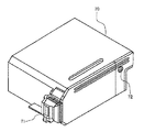
(記録ユニット、画像記録装置、画像形成方法)
次に本発明にかかる記録装置について説明する。本発明には記録ヘッドの記録インクに記録信号を与え、その発生した熱エネルギーにより液滴を吐出する方式が好ましい。その装置の主要部である記録ヘッドの構成を図1、図2、図3に示す。
【0113】
ヘッド13はインク流路14を形成したガラス、セラミックまたはプラスチック等と感熱記録に用いられる発熱抵抗体を有する発熱ヘッド15(図ではヘッドが示されているが、これに限定されない)とを接着して得られる。この発熱ヘッド15は酸化シリコン等で形成される保護膜16、アルミニウム電極17-1、17-2、ニクロム等で形成される発熱抵抗体層18、蓄熱層19、アルミナ等の放熱性のよい基板20よりなっている。
【0114】
記録インク21は吐出オリフィス22まで来ており、圧力Pによりメニスカス23を形成している。
【0115】
ここで電極17-1、17-2に電気信号が加わると、発熱ヘッド15nで示される領域が急激に発熱し、ここに接しているインク21に気泡が発生する。その圧力でメニスカスが吐出し、オリフィス22より記録液滴24となり、記録材25に向かって飛翔する。図3には図1に示したノズルを多数並べた、マルチ溝26を有する記録ヘッドの概略図を示す。該記録ヘッドは多数の流路を有するガラス板等27と図1において説明したヘッドと同様の発熱ヘッド28を密着して作られる。
【0116】
なお図1はインクの流路に沿ったヘッド13の断面図であり、図2は図1のA-B線での断面図である。
【0117】
図4にはこのヘッドを組み込んだインクジェット記録装置の1例を示す。ここでブレード61はワイピング部材であって、その一端はブレード保持部材によって保持されて固定端となり、カレンチレバーの形態をなしている。このブレードは記録ヘッドによる記録領域に隣接した位置に配置され、記録ヘッドの移動方向と垂直な方向に移動して吐出口面と当接し、キャッピングを行なう構成を有している。
【0118】
さらに63はブレードに隣接して設けられるインク吸収体であり、このブレードと同様に記録ヘッドの移動経路中に突出した形態で保持される。このブレード61、キャップ62、吸収体63によって吐出回復部64が構成され、ブレード61および吸収体63によってインク吐出口面に水分、塵等の除去が行なわれる。
【0119】
65は吐出エネルギー発生手段を有し、吐出口を配した吐出口面に対向する記録材にインクを吐出して記録を行なう記録ヘッドであり、66は記録ヘッド65を搭載して記録ヘッドの移動を行なうためのキャリッジである。このキャリッジはガイド軸67と摺動可能に係合し、このキャリッジの一部はモータ68によって駆動されるベルト69と接続(図示せず)している。これによりこのキャリッジはガイド軸に沿った移動が可能となり、記録ヘッドによる記録領域およびその隣接した領域の移動が可能となる。
【0120】
一方51は被記録材を挿入するための被記録材供給部、52はモータ(図示せず)により駆動される送りローラーである。これらの構成によって記録ヘッドの吐出口面と対向する位置、即ち記録位置へ被記録材が搬送され、記録が進行するにつれて、ローラー53を配した排出部へ排出される。
【0121】
上記構成において記録ヘッドが記録終了等でホームポジションに戻る際、ヘッド回復部64のキャップ62は記録ヘッドの移動経路から退避しているが、ブレードは移動経路中に突出している。この結果、記録ヘッドの吐出口面がワイピングされる。なおキャップが記録ヘッドの吐出口面に当接してキャッピングを行なう場合にはキャップは記録ヘッドの移動経路中に突出するように移動する。
【0122】
記録ヘッドがホームポジションから記録開始位置へ移動する場合にはキャップおよびブレードは前記したワイピング時の位置と同一の位置にある。この結果、この移動においても記録ヘッドの吐出口面はワイピングされる。
【0123】
前記の記録ヘッドのホームポジションへの移動には記録終了時や吐出回復時ばかりではなく、記録ヘッドが記録のために記録領域を移動する間に所定の間隔で記録領域に隣接したホームポジションへ移動し、この移動に伴って上記ワイピングが行なわれる。
【0124】
図5ではヘッドにインク供給部材、例えばチューブを介して供給されるインクを収容したインクカートリッジ45の一例を示す。ここで40は供給用インクを収容したインク収容部、例えばインク袋であり、その先端にはゴム製の栓42が設けられている。この栓に針(図示せず)を挿入することによりインク袋40中のインクをヘッドに供給可能にする。44は廃インクを受容する吸収体である。
【0125】
インク収容部としては、インクとの接触面がポリオレフィン、特にポリエチレンで形成されているものが好ましい。またカートリッジの他の態様として、該ブラックインクと該カラーインクとを各々個別に収容した2つの収容部を有し、該ブラックインクおよび該カラーインクを吐出させるためのヘッドに対して着脱可能に構成され、かつ各々のインクが該記録ヘッドに供給可能に構成されているカートリッジを挙げることができる。
【0126】
図12はそのようなカートリッジ 1401 の一例を示すものであり、1403 はブラックインクを収容したブラックインクの収容部、1405 がカラーインクを収容したカラーインクの収容部であり、該カートリッジは図13に示す様に該ブラックインクおよび該カラーインクの各々を吐出せしめる記録ヘッド 1501 に着脱可能に構成されてなると共に、該カートリッジ 1401 を記録ヘッド 1501 に装着した状態では該液体組成物及び該インクが記録ヘッド 1501 に供給される様に構成されているものである。
【0127】
本発明で使用されるインクジェット記録装置としては、前記のようなヘッドとインクカートリッジが別体となったものに限らず、図6に示すようなそれらを一体とした記録ユニットも好適に用いられる。
【0128】
図6では70は記録ユニットであって、この中にインクを収容したインク収容部、例えばインク吸収体が収納されており、このようなインク吸収体中のインクが複数のオリフィスを有するヘッド部71からインク滴として吐出される構成になっている。インク吸収体の材料としては、例えばポリウレタンを用いることができる。72は記録ユニット内部を大気に連通させるための大気連通口である。この記録ユニットは図4で示す記録ヘッドに変えて用いられるものであって、キャリッジ66に脱着自在になっている。
【0129】
更に本発明にかかる記録ユニットの他の実施態様として、該ブラックインクとカラーインク(例えばイエロー、マゼンタ、シアン、レッド、グリーンおよびブルーから選ばれる少なくとも1つのカラーインク)とを、1個のインクタンク内の各々のインク収納部に収納し、且つ各々のインクを吐出させる為の記録ヘッドを一体的に備えた記録ユニット、具体的には例えば図14に示す様に該ブラックインクを収容部 1601Bkに、またイエロー、シアン及びマゼンタのカラーインクを各々カラーインク収納部 1601Y、1601Cおよび 1601Mに収納し、更に各々のインクを各々個別に吐出させることができる様にインク流路を分けて構成した記録ヘッド 1603 を備えている様な記録ユニット 1601 が挙げられる。
【0130】
なお本発明に使用する記録装置では、インクに熱エネルギーを作用させてインクを吐出するインクジェット記録装置を例に挙げたが、本発明は、例えば力学的エネルギーをインクに作用させてインクを吐出する方式の記録装置、例えば圧電素子を使用するピエゾ方式のインクジェット記録装置に対しても同様に適用可能である。
【0131】
その記録装置の主要部である記録ヘッドの構成例を図15に示す。ヘッドは、インク室(不図示)に連通したインク流路 1701 と、所望の体積のインク滴を吐出するためのオリフィスプレート 1703 と、インクに直接圧力を作用させる振動板 1705 と、この振動板 1705 に接合され、電気信号により変位する圧電素子 1707 と、オリフィスプレート 1703 、振動板等を指示固定するための基板 1709 とから構成されている。
【0132】
図17において、インク流路 1701 は、感光性樹脂等で形成され、オリフィスプレート 1703 は、ステンレス、ニッケル等の金属を電鋳やプレス加工による穴あけ等により吐出口 1711 が形成され、振動板 1705 はステンレス、ニッケル、チタン等の金属フィルム及び高弾性樹脂フィルム等で形成され、圧電素子 1707 は、チタン酸バリウム、PZT等の誘電体材料で形成される。
【0133】
以上のような構成の記録ヘッドは、圧電素子 1707 にパルス状の電圧を与え、ひずみ応力を発生させ、そのエネルギーが圧電素子 1707 に接合された振動板を変形させ、インク流路 1701 内のインクを垂直に加圧しインク滴(不図示)をオリフィスプレートの吐出口 1711 より吐出して記録を行うように動作する。この様な記録ヘッドは図4に示したものと同様な記録装置に組み込んで使用される。記録装置の細部の動作は先述と同様に行うもので差しつかえない。
【0134】
また、本発明にかかる画像形成方法は、ブラック画像領域をブラックインクのみを付与する工程とブラックインクおよびカラーインクを付与する工程とで形成されていればよく、ブラックインクおよびカラーインクの付与方法等については特に規定されない。例えば、上記した米国特許第5428383号、米国特許第5488402号、および米国特許第5976230号に記載されているような処理方法にも用いることができる。
【0135】
【実施例】
以下、実施例および比較例を用いてさらに具体的に説明するが、本発明は、その要旨を越えない限り、下記実施例により限定されるものではない。尚、以下の記載で、部、%とあるものは特に断らない限り質量基準である。
はじめに顔料分散体1の調製を行った。
【0136】
顔料分散体1
比表面積が 230m2/gでDBP吸油量が70mL/100gのカーボンブラック10gとp-アミノ-N-安息香酸 3.41gを水72gに良く混合した後、これに硝酸 1.62gを滴下して、70℃で攪拌した。ここに更に数分後、5gの水に 1.07gの亜硝酸ナトリウムを溶かした溶液を加え、更に1時間攪拌した。得られたスラリーを濾紙(商品名:東洋濾紙No.2;アドバンティス社製)で濾過し、濾取した顔料粒子を十分に水洗し、90℃のオーブンで乾燥させ、更に、この顔料に水を足して顔料濃度10質量%の顔料水溶液を作製した。以上の方法によりカーボンブラックの表面に下記化学式に示される基を導入した。
【0137】
【化3】

次に上記の各顔料分散体を用いてブラックインク1、および比較例であるブラックインク2を下記の方法にて調整した。
【0139】
【0140】
【0141】
![]()
【0142】
【表1】
下記表2に上記実施例1および実施例2および比較例1のインクセットの主たる構成を示す。
【0144】
【表2】
上記の実施例1、実施例2及び比較例1、比較例2のインクを用いて、市販コピー用紙に記録を行った。インクジェット記録装置としては、記録信号に応じた熱エネルギーをインクに付与することによりインクを吐出させるオンデマンド型マルチ記録ヘッドを有する3種類のインクジェット記録装置(商品名:BJF-600、BJF-800、BJF-850;キヤノン(株)社製)を、各々1/600inch平方の領域に、ブラックインクは30ng、カラーインクは15ng相当のインクを付与できるように改造したものを用いた。
【0146】
上記実施例および比較例のインクセットのブリード、白モヤおよびカラーインクとブラックインクとの重畳によって形成したブラック画像領とブラックインク単独で形成したブラック画像領域との間の濃度差について以下の方法および基準で評価を行なった。
【0147】
尚、例えば、「Bk:100%duty ,Col:15%duty 」の処理とは、画像面積の100%の領域にブラックインクを付与し、その画像面積の15%の領域にはカラーインクも付与することを意味する。また、15%の領域にカラーインクを付与する場合、実施例1、比較例1、2はC、M、Yをそれぞれ5%ずつ付与し、実施例2はCのみを15%付与する。
【0148】
(ブリードおよび白モヤ)
印字パターンとしては図16のようなカラーとブラックの画像領域が隣接するものを印字し、境界部のブリードとブラック領域の白モヤの評価を目視で行った。
【0149】
この際、ブラックの画像領域はBk:100%duty ,Col:15%dutyとなるように処理を行った。
【0150】
・ブリードについての評価基準
A: 境界部のにじみがない。
B:境界部にややにじみが目立つ。
C:境界部のにじみがかなり目立つ。
【0151】
・白モヤについての評価基準
A:白モヤがない。
B:白モヤはやや目立つ。
C:全体的に白モヤが目立つ。
【0152】
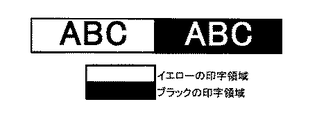
(ブラック画像領域の濃度差)
図17のように▲1▼Bk:100%duty 、▲2▼Bk:100%duty ,Col:5%duty、▲3▼Bk:100%duty ,Col:15%dutyの3種類のブラックベタ画像領域が隣接する画像パターンを形成し、画像間の濃度差や均一感の評価を目視で行った。
【0153】
・濃度差についての評価基準
A:ブラックベタの境界が目立たず、均一感がある。
B:ブラックベタの境界は目立たないが、均一感がない。
C:ブラックベタの境界が目立つ。
【0154】
評価結果を表3に示す。
【0155】
【表3】
以上より、本願発明にかかるインクセットを用いて画像を形成した場合、ブリードおよび白モヤが防止できるだけでなく、ブラックインク単独で形成したブラック画像と、ブラックインクおよびカラーインクとの重畳によって形成したブラック画像との間で視覚的に濃度差のない、均一感のある画像が得られることが確認された。
【0157】
【発明の効果】
以上説明したように、本発明の各実施態様によれば、ブラックインクとカラーインクとの間にブリードや白モヤが生じることなく、また、ブラック画像の形成方法によらず黒色画像は高い光学濃度を得られ、視覚的に均一感のある画像を得ることができるという効果を奏するものである。
【0158】
また、本発明の各実施態様によれば、より滑らかなモノトーン画像を容易に得ることができる。
【図面の簡単な説明】
【図1】インクジェット記録装置のヘッド部の縦断面図である。
【図2】インクジェット記録装置のヘッド部のA-B線による切断面の図である。
【図3】インクジェット記録装置のヘッド部の外観斜視図である。
【図4】インクジェット記録装置の一例を示す斜視図である。
【図5】インクカートリッジの縦断面図である。
【図6】記録ユニットの斜視図である。
【図7】塩を含む顔料インクを記録媒体に付与したときの固液分離の過程を示す模式図である。
【図8】塩を含まない顔料インクを記録媒体に付与したときの固液分離の過程を示す模式図である。
【図9】本発明にかかるインクセットを用いた時に、ブラックインクとカラーインクの付与順によらず高濃度の黒色画像が得られることを説明する図である。(a)〜(c)は、被記録材に対して浸透し難いブラックインクを付与した後に浸透しやすいカラーインクを付与したときの被記録材へのインクの定着工程を示す。(d)〜(f)は、被記録材に対して浸透しやすいカラーインクを付与した後に浸透し難いブラックインクを付与したときの被記録材へのインクの定着工程を示す。
【図10】aは本発明にかかるインクセットを用いてブラックインクとカラーインクを重畳した画像、bは本発明にかかるブラックインクのみで形成した画像、cは塩を含まない顔料インクのみで形成した画像であり、それぞれの光学濃度の関係を示した図である。
【図11】インク中の塩の有無、インク中の顔料濃度と光学濃度との関係を示すグラフである。
【図12】本発明の一実施態様にかかるインクカートリッジの概略平面図である。
【図13】図12のカートリッジが記録ヘッドに装着された状態を示す概略平面図である。
【図14】本発明の一実施態様にかかる記録ユニットの概略斜視図である。
【図15】インクジェットプリンタの記録ヘッド部の一態様のオリフィス部の拡大図である。
【図16】ブリード及び白モヤの評価実験に使用する印字パターン。
【図17】画像処理によるブラック画像領域の濃度差に関する評価実験に使用する画像パターン。
【符号の説明】
13 ヘッド
14 溝
15 発熱ヘッド
16 保護膜
17-1 アルミニウム電極
17-2 同上
18 発熱抵抗体
19 蓄熱層
20 基板
21 インク
22 オリフィス
23 メニスカス
24 記録小滴
25 記録材
26 マルチ溝
27 ガラス板
28 発熱ヘッド
40 インク袋
42 栓
44 インク吸収体
45 インクカートリッジ
51 記録材
52 紙送りローラ
53 排紙ローラ
61 ワイピング部材
62 キャップ
62' 同上
63 インク吸収体
64 吐出回復部
65 記録ヘッド
65' 同上
66 キャリッジ
67 ガイド軸
68 モータ
69 ベルト
70 記録ユニット
71 ヘッド部
72 大気連通口
901、1201 塩を含む顔料インク
1001、1101 塩を含まない顔料インク
905、1005 インク中の固体成分の豊富に含まれる領域
903、1003 記録媒体
907、1009 溶剤の浸透先端
1007 インク中の固形分の浸透先端
1301 ブラックインク
1303 記録媒体
1305 カラーインク
1309 凝集物
1401 カートリッジ
1403 ブラックインクの収容部
1405 カラーインクの収容部
1501、1603 記録ヘッド
1601 記録ユニット
1601Bk ブラックインク収容部
1601Y カラーインク(イエロー)収容部
1601C カラーインク(シアン)収容部
1601M カラーインク(マゼンタ)収容部
1701 インク流路
1703 オリフィスプレート
1705 振動板
1707 圧電素子
1709 基板
1711 吐出口[0001]
BACKGROUND OF THE INVENTION
The present inventionInk setAbout.
[0002]
[Prior art]
The ink jet recording method is a low noise and non-impact recording method for recording an image by directly ejecting ink onto a recording material. In addition, since this method does not require a complicated device for implementation, it is easy to reduce the running cost, reduce the size of the device, and make it color.
[0003]
Therefore, recording apparatuses such as printers, copying machines, facsimile machines, word processors, etc., to which the inkjet recording method is applied have been put into practical use. In addition, by using such an ink jet recording technique, multi-color using black ink and color ink (for example, at least one color ink selected from yellow ink, cyan ink, magenta ink, red ink, green ink and blue ink) is used. A color ink jet recording apparatus for forming the image is also put into practical use.
[0004]
However, on the other hand, when two different types of ink are applied to the recording material adjacent to each other in the ink jet recording method, the inks are mixed with each other at the boundary portion, and the quality of the color image is deteriorated ( There is a problem that bleeding) occurs. In particular, color mixing at the boundary between black ink and color ink has a great influence on image quality degradation, and various solutions have been developed.
[0005]
A typical solution is that when two kinds of inks are applied to the recording material adjacent to each other, at least one of the thickenings or at least one of the coloring materials is aggregated or precipitated to cause bleeding. An ink set and a recording method having a mechanism for preventing the above.
[0006]
For example, US Pat. No. 5,428,383 includes a precipitating agent (eg, a polyvalent metal salt) in one ink, and in the form of an organic dye having carboxyl and / or carboxylate groups in another ink, preferably a black ink. The use of a colorant is disclosed. When these inks are printed next to each other, the first ink having the precipitating agent causes precipitation of the colorant having carboxyl and / or carboxylate groups, thereby causing other inks of the colorant to be printed. It is described that the bleed between two adjacent print areas is reduced.
[0007]
US Pat. No. 5,976,230 discloses a technique for preventing bleeding by applying two types of inks that react with each other to the same region.
[0008]
[Problems to be solved by the invention]
According to the study by the present inventors, as described in the above-mentioned U.S. Pat. No. 5,976,230, an image obtained by a method of applying two kinds of reactive inks to the same region has a density of It has been confirmed that it rises higher than that of the image with a single ink. In Japanese Patent Application Laid-Open No. 6-171208 relating to the application of the present applicant, the black ink alone is formed by landing the pigment-based black ink and the color ink containing salt on the same point on the recording medium by the ink jet method. It is disclosed that an image having a higher density than that of a black image was obtained. Such an increase in the image density by overlapping the reactive ink sets is not a problem in itself.
[0009]
However, if a black region in the same document contains a portion formed only with black ink and a portion formed by mixing color ink and black ink, the black image density will be different from each other, and visually. The image may become uncomfortable. More specifically, there is a black character part (first character part) having no color background and a black character part (second character part) having a color background in one document, From the viewpoint of preventing bleeding, the first character portion is formed of the black ink alone, and the black ink and the color ink having reactivity with the black ink according to the method disclosed in US Pat. No. 5,976,230 are used. When they are formed in an overlapping manner, the density of the first character part and the density of the second character part are clearly different visually, which may cause a sense of incongruity.
[0010]
As one of the solutions, a processing method of fixing the black ink by placing the color ink that interacts with the black ink in the entire image area of the black ink, that is, in the above example, the first character portion. However, in this case, the consumption of color ink is increased, and the color ink that has been struck first usually has high permeability, so it is easier to spread than black ink on the recording medium. In some cases, the character may be visually recognized as if the character is bordered by color ink.
[0011]
As a result of repeated studies in view of the above knowledge, the present inventors have obtained the density of an image formed with only black ink by mixing black ink and color ink having reactivity with the black ink. The present inventors have found a technique capable of improving the image density to almost the same level as the obtained image density and have accomplished the present invention.
[0012]
Accordingly, an object of the present invention is to provide a high optical density, image quality, and image fastness required for a black image without causing problems such as an increase in ink consumption and a decrease in black character quality, including at least black ink and color ink. This black ink does not cause bleed or white smear with other color inks, and the optical density changes even if some processing is applied to the black ink image area. Is smallInk setIt is to provide.
[0013]
[Means for Solving the Problems]
The above object can be achieved by the following present invention. That is, the present inventionTakeThe ink set is an ink set including black ink and color ink, and the black ink isAs a salt (M1) 2 SO Four , CH Three COO (M1), Ph-COO (M1), (M1) NO Three , (M1) Cl, (M1) Br, (M1) I, (M1) 2 SO Three And (M1) 2 CO Three At least one selected from (M1 represents an alkali metal, ammonium or organic ammonium, and Ph represents a phenyl group);, Aqueous mediumAnd carbon black in which an anionic group is bonded to the surface of the carbon black directly or through another atomic group,And at least one color of the color ink isDye and Mg 2+ , Ca 2+ , Cu 2+ , Co 2+ , Ni 2+ , Fe 2+ , La 3+ , Nd 3+ , Y 3+ And Al 3+ A polyvalent metal salt having a polyvalent metal cation selected fromIt is characterized by including.
[0019]
The above configurationBy adopting it, black ink does not cause bleed or white smear between other color inks, and a black image formed by black ink alone is formed by overlapping color ink and black ink. As a result, it is possible to obtain an extremely high density substantially equal to that of the black image, and to obtain a high-quality image having a visually uniform feeling.
[0020]
The reason why these effects can be obtained is that the black ink applied on the recording medium is quickly separated into solid and liquid by the salt in the ink, and the pigment remains as a sufficient solid content on the surface of the recording medium. The density is much higher than the optical density of an image formed with a conventional black ink that does not contain salt that penetrates into the medium, and cannot be reproduced by adjusting the color material density. The optical density of the image formed with the salt-containing black ink alone shows a high optical density which is substantially equal to the optical density of the image when the black ink aggregates on the recording material.
[0021]
Furthermore, even when black ink and color ink are applied in an overlapping manner to express a monotone, an optical density difference occurs for the same reason as described above in the conventional technology. However, there is a limitation in the mixing ratio of black ink and color ink, causing problems such as a decrease in the degree of freedom in design and the deterioration of smooth gradation expression itself. However, by adopting the present invention, it is possible to make the optical density of the part where the black ink is aggregated and the optical density of the part formed only with the black ink almost equal, so the color ink is added to the black ink. Arbitrary gradation expression can be obtained by adjusting the ratio to be performed, and another effect that a more excellent image of multi-gradation expression can be realized.
[0022]
DETAILED DESCRIPTION OF THE INVENTION
An ink set according to an embodiment of the present invention includes a dye that destabilizes dispersion stability of a pigment in the black ink when the color ink and the black ink are mixed, and a pigment in the black ink One feature is that a color ink containing at least one of additives that destabilize the dispersion stability and a black ink containing salt are used. Here, destabilization of the dispersion stability of the pigment in the black ink specifically refers to aggregation or precipitation of the pigment, thickening of the black ink, or the like. Thickening means a phenomenon when the viscosity of an ink obtained by mixing both the black ink and the color ink before mixing becomes higher than that of the black ink and the color ink.
[0023]
(Reactivity of black ink and color ink)
The composition of the black ink and the color ink according to the present invention is prepared so as to destabilize the dispersion stability of the pigment in the black ink as described above when the black ink and the color ink are mixed. It is preferable. In particular,
For example
(1) an embodiment containing a dye that destabilizes the dispersion stability of the pigment in the black ink when the color ink is mixed with the black ink;
(2) A mode in which the color ink contains an additive that destabilizes the dispersion stability of the pigment in the black ink when mixed with the black ink.
[0024]
If the aspect of said (1) is described in detail, the following i) and ii) will be mentioned, for example.
[0025]
i) An example in which the pigment in the black ink has an anionic group and the dye of the color ink has a cationic group.
[0026]
In this example, when the color ink and the black ink are mixed, the cationic group of the dye of the color ink reacts with the anionic group of the pigment in the black ink, causing the dispersion in the pigment in the black ink, Aggregates the pigment and thickens the ink.
[0027]
ii) An example in which the pigment in the black ink has a cationic group and the dye in the color ink has an anionic group.
[0028]
In this example, when the color ink and the black ink are mixed, the anionic group of the dye in the color ink reacts with the cationic group of the pigment in the black ink, and as a result, the pigment in the black ink is dispersed and destroyed. Cause the pigment to aggregate and thicken the ink.
[0029]
If the aspect of said (2) is described in detail, the following iii) -v) will be mentioned, for example.
[0030]
iii) The pigment in the black ink has an anionic group, and the color ink is a polyvalent metal salt comprising a polyvalent metal cation, such as Mg2+, Ca2+, Cu2+, Co2+, Ni2+, Fe2+, La3+, Nd3+, Y3+And Al3+An example prepared so as to have at least one polyvalent metal salt comprising a polyvalent metal cation selected from:
[0031]
In this example, when the color ink and the rack ink are mixed, the polyvalent metal cation of the polyvalent metal salt in the color ink reacts with the anionic group of the pigment in the black ink, resulting in the black ink. The pigment causes dispersion breakage, aggregates the pigment, and thickens the ink. Here, as the polyvalent metal salt to be contained in the color ink, it is preferable to contain, for example, about 0.1 to 15% by mass with respect to the total mass of the color ink.
[0032]
iv) An example in which the pigment in the black ink is stably dispersed at a pH of 3 to 7 and the color ink is adjusted to a pH of 8 to 11.
[0033]
In this example, when the color ink and the black ink are mixed, the pH of the black ink increases, so that the dispersion stability of the pigment is destroyed, the pigment is aggregated, and the ink is thickened.
[0034]
v) An example in which the pigment in the black ink is stably dispersed at a pH of 7 to 11 and the color ink is adjusted to a pH of 3 to 6.
[0035]
In this example, when the color ink and the black ink are mixed, the pH of the black ink is lowered, so that the dispersion stability of the pigment is destroyed, the pigment is aggregated, and the ink is thickened.
[0036]
By using such an ink set, the difference in image density between the image formed by the black ink alone and the image formed by superimposing the black ink and the color ink in order to alleviate bleed and white mist is visually observed. The effect that it can be reduced to such an extent that it can hardly be recognized is obtained.In the present invention, the embodiment i) is used.
[0037]
The reason why such an effect is obtained will be described below.
[0038]
(Image formed with black ink and color ink)
First, in order to reduce bleeding and white haze, a high density image is formed by superimposing a pigment black ink and a color ink containing a dye or an additive that destabilizes the dispersion stability of the pigment in the black ink. The reason why it is obtained will be explained.
[0039]
When processing for mitigating bleed and white smear using black ink and color ink, the following two methods with different ink application orders are conceivable.
[0040]
First, the phenomenon occurring on the recording material by the method of applying the black ink after the color ink is applied is shown in FIGS. 9 (d) to 9 (f). FIGS. 9D to 9F show a black ink containing salt and a color ink reactive with the black ink, specifically, for example, a dye that destabilizes the dispersion stability of the pigment in the black ink. When the color ink is used, the black ink and the color ink are applied to the same place.
[0041]
Since the
[0042]
Here, when the component that destabilizes the dispersion stability of the pigment in the color ink is the color material itself in the color ink (the aspect (1) above), The dye that penetrates into the recording medium also participates in the formation of the aggregate. On the other hand, when the destabilizing component of the pigment dispersion stability is an additive such as a divalent metal salt (in the case of (2) above), the dye in the color ink penetrates into the recording medium. The divalent metal salt that destabilizes the dispersion stability of the pigment is considered to cause many aggregates and remain in the vicinity of the surface of the recording medium. In both cases (1) and (2), the pigment that was not involved in the reaction was put on the
[0043]
As described above, in any case, the color material occupancy rate on the surface of the recording medium which is considered to determine the image density and within a depth range of about 15 to 30 μm from the surface of the recording medium is very high. High image density will be achieved.
[0044]
Next, the case where the color ink is applied after the black ink is applied is shown in FIGS. When the black ink with low penetrability covers the recording medium as shown in FIG. 9A, the
[0045]
In such a situation, since the penetration of the
[0046]
As described above, when the color ink is applied after the black ink, the dye in the color ink is put on the
[0047]
According to the ink set used here, the images formed by both the above methods are almost the same at least visually and have a high image density regardless of the application order of the black ink and the color ink. In addition, since the color material in the ink is fixed as an aggregate above the recording material, even if the black ink and the color ink are superimposed on the recording material, the color ink having high permeability covers the pigment. It is possible to suppress penetration into the recording material.
[0048]
As a result, the generation of bleed and white haze can be effectively mitigated. Furthermore, even in the case of forming a monotone image, it is not necessary to consider the order of ink application, and more excellent gradation expression can be realized more easily.
[0049]
(Image formed with black ink alone)
Next, it is considered that the mechanism by which the black ink according to the present invention can obtain an image having a density that is almost the same as the density of the image obtained by superimposing the black ink and the color ink as described above is as follows. .
[0050]
7 (a) to 7 (c) and FIGS. 8 (a) to 8 (c), respectively, eject each of the salt-containing ink according to the present invention and the salt-free ink from the orifice by the ink jet recording method. FIG. 3 is an explanatory view schematically and conceptually showing the state of solid-liquid separation that occurs when applied to a recording medium having relatively high permeability such as plain paper. That is, immediately after ink landing, as shown in FIGS. 7 (a) and 8 (a), the
[0051]
As shown in FIG. 7B, the pigment ink to which salt has been added after the time T1 has rapidly separated into solid and liquid, and the
[0052]
After time T2 has elapsed: As shown in FIG. 7C, the pigment ink to which salt has been added penetrates further into the interior of the paper, but the
[0053]
The times T1 and T2 in the above description are reference times for conceptually grasping the difference in solid-liquid separation depending on the presence or absence of salt.
[0054]
As is apparent from the above, since the solid-liquid separation occurs quickly by adding salt, the solution penetrates into the recording material and the pigment penetrates into the recording material at a relatively fast stage after landing. Since it tends to stay above the recording material, the optical density is considered to increase. As described above, the black ink is generally set to have a higher surface tension than the color ink, and does not overlap with the color ink so as to increase the penetrability of the black ink into the recording medium. In the state, the black ink according to the present invention has a depth of about 15 to 30 μm on the surface of the recording medium substantially defining the image density and on the surface of the recording medium due to its rapid solid-liquid separation. The occupancy of the pigment in the region is greatly improved. As a result, the density of the image formed by the black ink alone can be greatly improved.
[0055]
FIG. 10 shows the effect of reducing the density difference due to the use of the ink set according to the present invention. In FIG. 10, the black image density a is the density of the image by superimposing the black ink and the color ink. Yes, b is the density of the image formed with the black ink alone containing the salt according to the present invention, and c is the density of the image formed with the black ink alone containing no salt used for the above control. As can be seen from this figure, the difference between the image densities a and c of the black ink is greatly reduced by using the ink set according to the present invention, and the difference between the image densities a and b is visually observed. Can be such that it is hardly recognizable.
[0056]
Next, the black ink and the color ink constituting the ink set according to the present invention will be described in detail.
[0057]
(About black ink)
For example, carbon black is preferably used as the pigment in the black ink. The dispersion form of carbon black in the ink may be a self-dispersion type or a dispersion form using a dispersant.
[0058]
(Self-dispersing carbon black)
Examples of self-dispersing carbon black include carbon black in which at least one hydrophilic group (anionic group or cationic group) is bonded to the surface of carbon black as an ionic group directly or via another atomic group. Is mentioned. By using this, the addition of a dispersant for dispersing carbon black is reduced or eliminated.
[0059]
In the case of carbon black in which an anionic group is bonded to the surface directly or via another atomic group, examples of the hydrophilic group bonded to the surface include, for example, —COO (M2), —SOThree(M2), -POThreeH (M2), -POThree(M2)2Etc. In the above formula, “M2” represents a hydrogen atom, an alkali metal, ammonium or organic ammonium. Among these, in particular, —COO (M2), —SOThreeThe self-dispersing carbon black in which (M2) is bonded to the carbon black surface and is anionicly charged can be used particularly preferably in this embodiment because of its good dispersibility in the ink.
[0060]
Of the hydrophilic groups represented by “M2”, specific examples of the alkali metal include Li, Na, K, Rb and Cs, and specific examples of the organic ammonium include, for example, methylammonium. Dimethylammonium, trimethylammonium, ethylammonium, diethylammonium, triethylammonium, methanolammonium, dimethanolammonium, trimethanolammonium and the like.
[0061]
The black ink according to the present invention containing self-dispersing carbon black in which M2 is ammonium or organic ammonium can further improve the water resistance of the recorded image, and can be used particularly preferably in this respect. . This is considered to be due to the fact that when the ink is applied onto the recording medium, ammonium is decomposed and ammonia is evaporated. Here, as a method for producing self-dispersing carbon black in which M2 is ammonium, for example, self-dispersing carbon black in which M2 is an alkali metal is replaced with ammonium by using an ion exchange method or H2 by adding an acid. For example, a method in which ammonium hydroxide is added to form M2 to ammonium after forming into a mold.
[0062]
An example of a method for producing an anionically charged self-dispersing carbon black is a method in which carbon black is oxidized with sodium hypochlorite. By this method, a —COONa group is chemically bonded to the surface of carbon black. be able to.
[0070]
By the way, various hydrophilic groups as described above may be directly bonded to the surface of carbon black. Alternatively, other atomic groups may be interposed between the carbon black surface and the hydrophilic group, and the hydrophilic group may be indirectly bonded to the carbon black surface. Here, specific examples of the other atomic groups include, for example, a linear or branched alkylene group having 1 to 12 carbon atoms, a substituted or unsubstituted phenylene group, and a substituted or unsubstituted naphthylene group. Here, examples of the substituent for the phenylene group and the naphthylene group include linear or branched alkyl groups having 1 to 6 carbon atoms. Specific examples of combinations of other atomic groups and hydrophilic groups include, for example, -C2HFourCOO (M2), -Ph-SOThree(M2), -Ph-COO (M2), etc. (where Ph represents a phenyl group).
[0071]
By the way, in the black ink according to the present invention, two or more of the above-described self-dispersing carbon blacks may be appropriately selected and used as the ink pigment. The addition amount of the self-dispersing carbon black in the ink is preferably in the range of 0.1 to 15% by mass, particularly 1 to 10% by mass with respect to the total mass of the ink. By setting this range, the self-dispersing carbon black can maintain a sufficiently dispersed state in the ink. Furthermore, for the purpose of adjusting the color tone of the ink, a dye may be added as a coloring material in addition to the self-dispersing carbon black.
[0072]
(Normal carbon black)
In addition, as a pigment for black ink, normal carbon black that is not self-dispersing can also be used.
[0073]
Examples of such carbon blacks include carbon black pigments such as furnace black, lamp black, acetylene black, and channel black. For example, Raven 7000, Ray Van 5750, Ray Van 5250, Ray Van 5000 ULTRA-, Ray Van 3500, and Ray Van 2000. , Ray-Van 1500, Ray-Van 1250, Ray-Van 1200, Ray-Van 1190 ULTRA-II, Ray-Van 1170, Ray-Van 1255 (made by Columbia), Black Pearls L, Legal 400R, Legal 330R, Legal 660R, Moguul ) L, Monarch 700, Monak 800, Monak 880, Monak 900, Monak 1000, Monak 1100, Monak 1300, Monak 1400, Vulcan XC-72R (above made by Cabot), Color Black (Color Black) FW1, color black FW2, Color Black FW2V, Color Black FW18, Color Black FW200, Color Black S150, Color Black S160, Color Black S170, Printex 35, Printex U, Printex V, Printex 140U, Printex 140V, Special Black ( Special Black 6, Special Black 5, Special Black 4A, Special Black 4 (manufactured by Degussa), No.25, No.33, No.40, No.47, No.52, No.900, No.2300 MCF-88, MA600, MA7, MA8, MA100 (manufactured by Mitsubishi Chemical Co., Ltd.) and the like can be used, but the invention is not limited to these, and conventionally known carbon black can be used.
[0074]
Further, magnetic fine particles such as magnetite and ferrite, titanium black and the like may be used as the black pigment.
[0075]
When such normal carbon black is used as a pigment for black ink, it is preferable to add a dispersant to the ink in order to stably disperse it in an aqueous medium.
[0076]
As the dispersant, for example, a dispersant having an ionic group and capable of stably dispersing carbon black in an aqueous medium by its action is suitably used. As such a dispersant, for example, specifically as a dispersant, Styrene-acrylic acid copolymer, styrene-acrylic acid-acrylic acid alkyl ester copolymer, styrene-maleic acid copolymer, styrene-maleic acid-acrylic acid alkyl ester copolymer, styrene-methacrylic acid copolymer Styrene-methacrylic acid-acrylic acid alkyl ester copolymer, styrene-maleic acid half ester copolymer, vinyl naphthalene-acrylic acid copolymer, vinyl naphthalene-maleic acid copolymer, styrene-maleic anhydride-maleic acid Examples thereof include acid half ester copolymers and salts thereof. Among these, those having a mass average molecular weight in the range of 1000 to 30000 are preferred, and more preferably in the range of 3000 to 15000.
[0077]
(About salt in black ink)
As the salt of the black ink according to the present invention, (M1)2SOFour, CHThreeCOO (M1), Ph-COO (M1), (M1) NOThree, (M1) Cl, (M1) Br, (M1) I, (M1)2SOThreeAnd (M1)2COThreeIt is preferable to use at least one selected from Here, M1 represents an alkali metal, ammonium or organic ammonium, and Ph represents a phenyl group.
[0078]
Specific examples of the alkali metal include Li, Na, K, Rb, and Cs. Specific examples of the organic ammonium include methylammonium, dimethylammonium, trimethylammonium, ethylammonium, diethylammonium, triethylammonium, Examples include trimethanol ammonium, dimethanol ammonium, trimethanol ammonium, ethanol ammonium, diethanol ammonium, and triethanol ammonium.
[0079]
Among the above-mentioned salts, sulfates (for example, potassium sulfate) and benzoates (for example, ammonium benzoate) are well compatible with self-dispersing carbon black, specifically, solid-liquid separation when applied to a recording medium. Because the effect is particularly excellent, it is possible to form inkjet recording images of particularly excellent quality on various recording media.
[0080]
By coexisting a salt as described above in an ink containing a pigment dispersed in an aqueous medium by the action of an ionic group, for example, an ink containing self-dispersing carbon black, the image quality depends on the type of recording medium. An ink that can stably form a high-quality image without greatly changing can be obtained.
[0081]
The detailed mechanism by which the black ink according to the present invention exhibits the above-described characteristics is not clear at the present time. However, with respect to the Ka value obtained by the Bristow method, which is known as a measure representing the penetrability of ink into a recording medium, the black ink according to the present invention is compared with an ink having the same composition except that no salt is added. The present inventors have obtained knowledge that a large Ka value is exhibited.
[0082]
An increase in the Ka value indicates that the permeability of the ink into the recording medium has been improved. As a common sense of those skilled in the art, the improvement in the permeability of the ink means a decrease in the optical density. It was. That is, it has been recognized by those skilled in the art that the optical density is lowered as a result of the penetration of the color material into the recording medium as the ink penetrates.
[0083]
And comprehensively judging from such various knowledge about the black ink according to the present invention, the salt in the black ink is separated from the solvent and solids in the ink after being applied on the paper surface (solid-liquid separation). ) Is considered to cause a specific action that causes it to occur very quickly. In other words, if solid-liquid separation is slow when the ink is applied to the recording medium, the ink diffuses isotropically with the colorant in the paper on the ink with a large Ka value or on the paper with a high ink permeability, As a result, the sharpness (character quality) of the character is impaired, and at the same time, the color material penetrates deep into the paper, so that the optical density is also expected to decrease.
[0084]
However, since such a phenomenon is not observed in the black ink according to the present invention, solid-liquid separation occurs quickly when applied to a recording medium, and as a result, despite the increase in the Ka value of the ink, It is presumed to give a different image. The same reason is considered to be the reason why it is difficult for the black ink according to the present invention to cause a phenomenon such as a decrease in character quality or a decrease in optical density even with paper having a relatively high permeability.
[0085]
The content of the pigment in the black ink according to the present invention, for example, self-dispersing carbon black, is 0.1 to 15% by mass, particularly 1 to 10% by mass with respect to the total mass of the ink. preferable. Further, the salt content is preferably in the range of 0.05 to 10% by mass, particularly 0.1 to 5% by mass with respect to the total mass of the ink. By making the content of the pigment and salt in the black ink within the above range, a more excellent effect can be enjoyed.
[0086]
When the above-described self-dispersing carbon black is used as a pigment, for example, —COO (M2), —SOThree(M2)2, -POThreeH (M2), -POThree(M2)2As described above, when M2 is used, ammonium or organic ammonium can be preferably used as M2, but at this time, as a salt in the black ink, for example, “M2” is matched, that is, “M1” = “M2”. "Is one of the preferred embodiments.
[0087]
That is, the present inventors made M2 (counter ion) and M1 of the hydrophilic group of the self-dispersing carbon black the same in the examination process of the effect of adding salt to the ink containing the self-dispersing carbon black. Occasionally, we have found that the stability of the ink is particularly improved. The reason why such an effect can be obtained by aligning M1 and M2 is not clear, but salt exchange does not occur between the counter ion of the hydrophilic group of the self-dispersing carbon black and the salt in the ink. It is presumed that the dispersion stability of the self-dispersing carbon black is stably maintained.
[0088]
If both M1 and M2 are ammonium or organic ammonium, in addition to the effect of stabilizing ink characteristics, the water resistance of the recorded image can be further improved. At this time, Ph—COO (NHFour) (Ammonium benzoate) can provide excellent results in the re-ejection properties of the ink from the head nozzle after the ink jet recording is temporarily stopped.
[0089]
(Aqueous medium in black ink)
Examples of the aqueous medium used in the black ink according to the present invention include water or a mixed solvent of water and a water-soluble organic solvent. As the water-soluble organic solvent, those having an ink drying preventing effect are particularly preferable.
[0090]
Specific examples include alkyl alcohols having 1 to 4 carbon atoms such as methyl alcohol, ethyl alcohol, n-propyl alcohol, isopropyl alcohol, n-butyl alcohol, sec-butyl alcohol, and tert-butyl alcohol; dimethylformamide, dimethyl Amides such as acetamide; Ketones or ketoalcohols such as acetone and diacetone alcohol; Ethers such as tetrahydrofuran and dioxane; Polyalkylene glycols such as polyethylene glycol and polypropylene glycol; Ethylene glycol, propylene glycol, butylene glycol, and triethylene Alkyl groups such as glycol, 1,2,6-hexanetriol, thiodiglycol, hexylene glycol, diethylene glycol and the like containing 2 to 6 carbon atoms Lenglycols; lower alkyl ether acetates such as polyethylene glycol monomethyl ether acetate; glycerin; polyhydric alcohols such as ethylene glycol monomethyl (or ethyl) ether, diethylene glycol methyl (or ethyl) ether, triethylene glycol monomethyl (or ethyl) ether Lower alkyl ethers; polyhydric alcohols such as trimethylolpropane and trimethylolethane; N-methyl-2-pyrrolidone, 2-pyrrolidone, 1,3-dimethyl-2-imidazolidinone and the like. The water-soluble organic solvents as described above can be used alone or as a mixture. It is desirable to use deionized water as the water.
[0091]
The content of the water-soluble organic solvent contained in the black ink according to the present invention is not particularly limited, but is preferably in the range of 3 to 50% by mass with respect to the total mass of the ink. The content of water contained in the ink is preferably in the range of 50 to 95% by mass with respect to the total mass of the ink.
[0092]
The black ink described above has an excellent effect that the dependency of the print quality on the recording medium characteristics can be extremely reduced. And the excellent point of the black ink concerning this invention is not only this.
[0093]
That is, FIG. 11 is a graph plotting the relationship between the pigment density and the optical density of the image of each ink for the black ink and a black ink having the same composition except that it does not contain salt. As can be seen from FIG. 11, the optical density of the image by any ink finally reaches a similar value, but the black ink (a) according to the present invention is lower than the control black ink (b). The knowledge that the saturation value was reached at the pigment concentration was obtained. In other words, the addition of salt makes it possible to reduce the pigment concentration in the ink without changing the optical density of the image.
[0094]
Specifically, for example, when about 1% by mass of ammonium benzoate is contained as a salt, the optical density of printing on plain paper is about 1.4, for example, by setting the concentration of self-dispersing carbon black to about 4% by mass. Even if the carbon black density is further increased, the optical density does not change much. On the other hand, in the case of ink containing no salt, the optical density of printing on plain paper is about 1.32 when the carbon black concentration is 4% by mass, and the optical density is 1.3 when the carbon black concentration is 7% by mass. Even in the case of 8 mass%, it is about 1.35, and this value is almost saturated.
[0095]
Even if the difference between the saturation values of optical density (1.4 and 1.35) is only 0.05 in terms of numerical value, the difference is clearly recognized visually when each printed product is compared. It is something that can be done. Ink added with salt in this way can produce a high optical density print even at a low carbon black density compared to an ink containing no salt, and provides a favorable result that the saturation value of the optical density itself is high. It is. Although a specific example using self-dispersing carbon was described here, the same phenomenon was observed for black ink in which carbon black was dispersed using a dispersant.
[0096]
This also brings the following benefits. That is, the ink containing salt has a characteristic that the margin of the carbon black density with respect to the optical density of the printed material is wide as described above. For this reason, for example, an ink tank having an absorber is filled with this ink, and the ink tank is left in the same posture for a long period of time (for example, left with the nozzle up for 6 months), and then printing is performed using the ink tank. It is extremely effective to prevent the difference in optical density that can be visually confirmed between the printed matter obtained at the initial stage of printing and the printed matter obtained immediately before the ink in the ink tank is used up. it can.
[0097]
The ink is excellent in intermittent ejection as another effect of adding salt. Intermittent discharge refers to a predetermined nozzle of the recording head, discharges ink from the nozzle, and then leaves it for a predetermined time without performing preliminary ink discharge or ink suction in the nozzle, and again from the nozzle. When ink is ejected, it is evaluated whether ink is ejected normally from the beginning of re-ejection.
[0098]
(Ink characteristics; ink jet ejection characteristics, permeability to recording media)
The black ink according to the present invention can be used for writing instrument ink and ink jet recording ink. As an ink jet recording method, there are a recording method in which mechanical energy is applied to ink to eject droplets, and a recording method in which thermal energy is applied to ink and ink droplets are ejected by foaming of the ink. The ink of the present invention is particularly suitable.
[0099]
By the way, when the black ink according to the present invention is used for inkjet recording, it is preferable that the ink has a characteristic that it can be ejected from an inkjet head. From the viewpoint of dischargeability from an ink jet head, the liquid has, for example, a viscosity of 1 to 15 mPa · s, a surface tension of 25 mN / m or more, particularly a viscosity of 1 to 5 mPa · s, and a surface tension of 25. It is preferable to set it to -50 mN / m.
[0100]
A Ka value obtained by the Bristow method is a measure representing the penetrability of ink into a recording medium. That is, the ink permeability is 1 m.2The ink permeation amount V (mL / m) after the predetermined time t has elapsed since the ink droplet was ejected.2= Μm) is shown by the Bristow equation shown below.
[0101]
V = Vr + Ka (t-tw)1/2
Here, immediately after the ink droplets adhere to the surface of the recording medium, the ink is mostly absorbed in the uneven portion of the surface of the recording medium (roughness portion of the surface of the recording medium) and almost penetrates into the inside of the recording medium. Not. The time between them is the contact time (tw), and the amount of ink absorbed in the uneven portion of the recording medium at the contact time is Vr.
[0102]
When the contact time is exceeded after the ink is deposited, the amount of penetration into the recording medium is increased by a time proportional to the time that exceeds the contact time, that is, the power of (t-tw). Ka is a proportional coefficient of this increase, and shows a value according to the penetration rate. The Ka value can be measured using a liquid dynamic permeability tester (eg, trade name: dynamic permeability tester S; manufactured by Toyo Seiki Seisakusho, etc.) by the Bristow method.
[0103]
In the ink according to each embodiment of the present invention, the Ka value is preferably less than 1.5 in order to further improve the recorded image quality, and more preferably 0.2 or more and less than 1.5. is there. That is, when the Ka value is less than 1.5, solid-liquid separation occurs at an early stage of the ink penetration into the recording medium, and a high-quality image with very little feathering can be formed.
[0104]
The Ka value according to the Bristow method in the present invention is PB used for plain paper (for example, a copy machine using an electrophotographic method, a page printer (laser beam printer) manufactured by Canon Inc., or a printer using an ink jet recording method). This is a value measured using a paper or a PPC paper which is a paper for a copying machine using an electrophotographic method as a recording medium. The measurement environment is assumed to be a normal office environment, for example, a temperature of 20 to 25 ° C. and a humidity of 40 to 60%.
[0105]
And as a composition of the preferable aqueous medium which carry | supports the above characteristics, it is preferable to contain glycerol, a trimethylol propane, thiodiglycol, ethylene glycol, diethylene glycol, isopropyl alcohol, and acetylene alcohol, for example.
[0106]
(About color ink)
As the dye that can be used in the color ink according to the present invention, a known dye such as an acid dye or a direct dye can be used. For example, as the anionic dye, any of existing ones and newly synthesized ones having appropriate color tone and density can be used. Moreover, it is also possible to mix and use any of these.
[0107]
Specific examples of the anionic dye are listed below.
[0108]
(Coloring material for yellow)
C.I.
C.I. Reactive Yellow 2, 3, 17, 25, 37, 42
C.I. Food Yellow 3
(Coloring material for red)
C.I.
C.I.
24, 31, 42, 45, 46, 59
C.I. Food Red 87, 92, 94
(Coloring material for blue)
C.I.
(Coloring material for black)
C.I.
C.I. Food Black 1, 2
(solvent)
Examples of the ink solvent or dispersion medium containing the dye for color ink as described above include water or water and a water-soluble organic solvent. Examples of the water-soluble organic solvent are the same as those described for the black ink. Further, when the color ink is attached to a recording medium by an ink jet method (for example, bubble jet method), the ink is prepared to have a desired viscosity and surface tension so as to have excellent ink jet discharge characteristics as described above. Things are preferable.
[0109]
(Dye content)
The content of the dye in the color ink shown here may be selected as appropriate so that, for example, when used in ink jet recording, the ink has excellent ink jet ejection characteristics and has a desired color tone and density. For example, the range of 3 to 50% by mass with respect to the total mass of the ink is preferable. Further, when importance is attached to the visual uniformity of the black image, it is particularly preferable that the concentration of the dye in the color ink is 10% by mass or less of the mass of the color ink as described above. The amount of water contained in the ink is preferably in the range of 50 to 95% by mass with respect to the total mass of the ink.
[0110]
(Color ink permeability)
Regarding the color ink as described above, it is preferable that the Ka value is, for example, 5 or more because a high-quality color image can be formed on the recording medium. That is, ink having such a Ka value has high penetrability into a recording medium, and therefore, even when recording images of at least two colors selected from yellow, magenta and cyan, for example, between adjacent images. Color bleeding (bleeding) can be suppressed, and even when these inks are overprinted to form a secondary color image, each ink has high penetrability, so that it is between adjacent different color images. Can effectively suppress bleeding. As a method for adjusting the Ka value of the color ink to such a value, a conventionally known method such as addition of a surfactant or addition of a permeable solvent such as glycol ether can be applied. Of course, the addition amount may be selected as appropriate.
[0111]
As described above, the color ink according to the present invention includes a dye that destabilizes the dispersion stability of the pigment in the black ink when mixed with the black ink, or when the dye is mixed with the black ink. And an additive that destabilizes the dispersion stability of the black ink, or a dye that destabilizes the dispersion stability of the pigment in the black ink when mixed with the black ink, and the black ink It is preferable to include an additive that destabilizes the dispersion stability of the pigment in the black ink when mixed. Specifically, it is the aspect of (1), (2), or (1) and (2) mentioned above regarding the reactivity between the black ink and the color ink, and more specifically,i), iii)The color inks may be prepared as shown in the aspects v to v), or the color ink and the black ink may be prepared by appropriately selecting materials that can be used for each of the inks described above.
[0112]
(Recording unit, image recording apparatus, image forming method)
Next, the recording apparatus according to the present invention will be described. In the present invention, it is preferable that a recording signal is given to the recording ink of the recording head and droplets are discharged by the generated thermal energy. The configuration of the recording head, which is the main part of the apparatus, is shown in FIGS.
[0113]
The
[0114]
The
[0115]
Here, when an electric signal is applied to the electrodes 17-1 and 17-2, the region indicated by the heat generating head 15n suddenly generates heat, and bubbles are generated in the
[0116]
1 is a cross-sectional view of the
[0117]
FIG. 4 shows an example of an ink jet recording apparatus incorporating this head. Here, the
[0118]
Further, reference numeral 63 denotes an ink absorber provided adjacent to the blade, and is held in a form protruding in the moving path of the recording head in the same manner as this blade. The
[0119]
Reference numeral 65 denotes a recording head which has discharge energy generating means and performs recording by discharging ink onto a recording material opposed to the discharge port surface on which the discharge ports are arranged. It is a carriage for performing. The carriage is slidably engaged with the guide shaft 67, and a part of the carriage is connected to a belt 69 (not shown) driven by a motor 68. As a result, the carriage can move along the guide shaft, and the recording area and its adjacent area can be moved by the recording head.
[0120]
On the other hand, 51 is a recording material supply unit for inserting a recording material, and 52 is a feed roller driven by a motor (not shown). With these configurations, the recording material is transported to a position facing the discharge port surface of the recording head, that is, a recording position, and is discharged to a discharge portion provided with a
[0121]
In the above configuration, when the recording head returns to the home position due to the end of recording or the like, the
[0122]
When the recording head moves from the home position to the recording start position, the cap and the blade are at the same position as that at the time of wiping. As a result, even in this movement, the ejection port surface of the recording head is wiped.
[0123]
The movement of the recording head to the home position is not only at the end of recording or at the time of ejection recovery, but also to the home position adjacent to the recording area at a predetermined interval while the recording head moves the recording area for recording. Then, the wiping is performed with this movement.
[0124]
FIG. 5 shows an example of an
[0125]
As the ink containing portion, an ink contact surface made of polyolefin, particularly polyethylene, is preferable. Further, as another aspect of the cartridge, it has two storage portions that individually store the black ink and the color ink, and is configured to be detachable from a head for discharging the black ink and the color ink. And a cartridge in which each ink can be supplied to the recording head.
[0126]
FIG. 12 shows an example of such a
[0127]
The ink jet recording apparatus used in the present invention is not limited to the one in which the head and the ink cartridge are separated, and a recording unit in which they are integrated as shown in FIG. 6 is also preferably used.
[0128]
In FIG. 6,
[0129]
Furthermore, as another embodiment of the recording unit according to the present invention, the black ink and the color ink (for example, at least one color ink selected from yellow, magenta, cyan, red, green and blue) are combined into one ink tank. A recording unit that is integrally provided with a recording head that is stored in each ink storage section and discharges each ink, specifically, for example, the black ink is stored in the storage section 1601Bk as shown in FIG. In addition, the recording heads are configured so that yellow, cyan and magenta color inks are stored in the color
[0130]
In the recording apparatus used in the present invention, an ink jet recording apparatus that discharges ink by applying thermal energy to the ink has been described as an example. However, the present invention discharges ink by applying mechanical energy to the ink, for example. The present invention can be similarly applied to a recording apparatus of a type, for example, a piezo type inkjet recording apparatus using a piezoelectric element.
[0131]
FIG. 15 shows a configuration example of a recording head which is a main part of the recording apparatus. The head includes an
[0132]
In FIG. 17, an
[0133]
The recording head configured as described above applies a pulsed voltage to the
[0134]
In addition, the image forming method according to the present invention is only required to form the black image region by the step of applying only the black ink and the step of applying the black ink and the color ink. There is no special provision for. For example, it can also be used in processing methods such as those described in US Pat. No. 5,428,383, US Pat. No. 5,488,402, and US Pat. No. 5,976,230.
[0135]
【Example】
Hereinafter, although it demonstrates more concretely using an Example and a comparative example, this invention is not limited by the following Example, unless the summary is exceeded. In the following description, parts and% are based on mass unless otherwise specified.
First, pigment dispersion 1 was prepared.
[0136]
Pigment dispersion 1
Specific surface area is 230m2After mixing 10 g of carbon black having a DBP oil absorption of 70 mL / 100 g and 3.41 g of p-amino-N-benzoic acid with 72 g of water, 1.62 g of nitric acid was added dropwise thereto and stirred at 70 ° C. A few minutes later, a solution of 1.07 g of sodium nitrite dissolved in 5 g of water was added, and the mixture was further stirred for 1 hour. The obtained slurry was filtered with a filter paper (trade name: Toyo Filter Paper No. 2; manufactured by Advantis), the pigment particles collected by filtration were thoroughly washed with water and dried in an oven at 90 ° C. Was added to prepare an aqueous pigment solution having a pigment concentration of 10% by mass. By the above method, a group represented by the following chemical formula was introduced on the surface of carbon black.
[0137]
[Chemical Formula 3]
Next, the black ink 1 and the black ink 2 as a comparative example were prepared by the following method using each pigment dispersion.
[0139]
[0140]
[0141]
![]()
[0142]
[Table 1]
Table 2 below shows the main configuration of the ink sets of Examples 1 and 2 and Comparative Example 1.
[0144]
[Table 2]
Recording was performed on commercially available copy paper using the inks of Examples 1 and 2 and Comparative Examples 1 and 2. As the ink jet recording apparatus, there are three types of ink jet recording apparatuses (trade names: BJF-600, BJF-800, having an on-demand multi-recording head that ejects ink by applying thermal energy corresponding to a recording signal to the ink. BJF-850 (manufactured by Canon Inc.) was used in a 1/600 inch square area so that 30 ng of black ink and 15 ng of color ink could be applied.
[0146]
Regarding the density difference between the black image region formed by superimposing the bleed, white fog, color ink, and black ink of the ink sets of the above examples and comparative examples and the black image region formed by the black ink alone, the following method and Evaluation was performed based on the criteria.
[0147]
For example, the processing “Bk: 100% duty, Col: 15% duty” means that black ink is applied to a region of 100% of the image area, and color ink is also applied to a region of 15% of the image area. It means to do. Further, when applying color ink to the 15% region, Example 1, Comparative Examples 1 and 2 give 5% each of C, M, and Y, and Example 2 gives 15% of C alone.
[0148]
(Bleed and white haze)
As the print pattern, a pattern in which the color and black image areas are adjacent as shown in FIG. 16 was printed, and the evaluation of the bleed at the boundary and the white haze in the black area was performed visually.
[0149]
At this time, the processing was performed so that the black image area was Bk: 100% duty and Col: 15% duty.
[0150]
・ Evaluation criteria for bleed
A: There is no blur at the boundary.
B: Slight blurring is noticeable at the boundary.
C: The blurring at the boundary is quite noticeable.
[0151]
・ Evaluation criteria for white haze
A: There is no white haze.
B: White haze is slightly noticeable.
C: Overall, white haze is noticeable.
[0152]
(Density difference in black image area)
As shown in FIG. 17, (1) Bk: 100% duty, (2) Bk: 100% duty, Col: 5% duty, (3) Bk: 100% duty, Col: 15% duty An image pattern in which the regions are adjacent to each other was formed, and the density difference between images and uniformity were evaluated visually.
[0153]
・ Evaluation criteria for concentration differences
A: The black solid border is inconspicuous and has a uniform feeling.
B: The black solid boundary is not noticeable, but there is no sense of uniformity.
C: The black solid border is conspicuous.
[0154]
The evaluation results are shown in Table 3.
[0155]
[Table 3]
As described above, when an image is formed using the ink set according to the present invention, not only bleed and white fog can be prevented, but also a black image formed by superimposing the black ink and the color ink with the black image formed alone. It was confirmed that a uniform image with no visual difference in density from the image was obtained.
[0157]
【The invention's effect】
As described above, according to each embodiment of the present invention, no bleed or white fog occurs between the black ink and the color ink, and the black image has a high optical density regardless of the black image forming method. And an image having a visually uniform feeling can be obtained.
[0158]
Moreover, according to each embodiment of the present invention, a smoother monotone image can be easily obtained.
[Brief description of the drawings]
FIG. 1 is a longitudinal sectional view of a head portion of an ink jet recording apparatus.
FIG. 2 is a cross-sectional view taken along line AB of the head portion of the ink jet recording apparatus.
FIG. 3 is an external perspective view of a head portion of the ink jet recording apparatus.
FIG. 4 is a perspective view illustrating an example of an ink jet recording apparatus.
FIG. 5 is a longitudinal sectional view of an ink cartridge.
FIG. 6 is a perspective view of a recording unit.
FIG. 7 is a schematic view showing a solid-liquid separation process when a pigment ink containing salt is applied to a recording medium.
FIG. 8 is a schematic diagram showing a solid-liquid separation process when a pigment ink containing no salt is applied to a recording medium.
FIG. 9 is a diagram illustrating that a high-density black image can be obtained regardless of the order of application of black ink and color ink when the ink set according to the present invention is used. (a)-(c) show the fixing process of the ink to the recording material when the color ink which is easy to permeate is applied after the black ink which is difficult to permeate the recording material is applied. (d) to (f) show the fixing process of the ink onto the recording material when the black ink which is difficult to permeate is applied after the color ink which is easy to permeate the recording material.
10A is an image in which black ink and color ink are superimposed using the ink set according to the present invention, b is an image formed only with the black ink according to the present invention, and c is formed only with pigment ink not containing salt. FIG. 6 is a diagram showing the relationship between the optical densities of the images.
FIG. 11 is a graph showing the relationship between the presence or absence of salt in the ink and the pigment concentration and optical density in the ink.
FIG. 12 is a schematic plan view of an ink cartridge according to an embodiment of the present invention.
13 is a schematic plan view showing a state in which the cartridge of FIG. 12 is mounted on the recording head.
FIG. 14 is a schematic perspective view of a recording unit according to an embodiment of the present invention.
FIG. 15 is an enlarged view of an orifice portion of one aspect of a recording head portion of an inkjet printer.
FIG. 16 is a printing pattern used for an evaluation experiment of bleed and white haze.
FIG. 17 is an image pattern used for an evaluation experiment regarding a density difference in a black image region by image processing.
[Explanation of symbols]
13 heads
14 groove
15 Heat generation head
16 Protective film
17-1 Aluminum electrode
17-2 Same as above
18 Heating resistor
19 Heat storage layer
20 substrates
21 ink
22 Orifice
23 Meniscus
24 recording droplets
25 Recording material
26 Multi-slot
27 Glass plate
28 Heating head
40 ink bag
42 stoppers
44 Ink absorber
45 Ink cartridge
51 Recording material
52 Paper feed roller
53 Paper discharge roller
61 Wiping members
62 cap
62 'Same as above
63 Ink absorber
64 Discharge recovery section
65 Recording head
65 'Same as above
66 Carriage
67 Guide shaft
68 motor
69 belt
70 recording units
71 Head
72 Air communication port
901, 1201 Pigment ink containing salt
1001, 1101 Pigment ink without salt
905, 1005 Areas rich in solid components in ink
903, 1003 Recording medium
907, 1009 Solvent penetration tip
1007 Penetrating tip of solid content in ink
1301 Black ink
1303 Recording media
1305 Color ink
1309 Aggregate
1401 cartridge
1403 Black ink container
1405 Color ink container
1501, 1603 Recording head
1601 Recording unit
1601Bk black ink container
1601Y color ink (yellow) container
1601C Color ink (cyan) container
1601M color ink (magenta) container
1701 Ink channel
1703 Orifice plate
1705 Diaphragm
1707 Piezoelectric element
1709 board
1711 Discharge port
Claims (3)
Priority Applications (4)
| Application Number | Priority Date | Filing Date | Title |
|---|---|---|---|
| JP2000265668A JP4683585B2 (en) | 1999-09-17 | 2000-09-01 | Ink set |
| US09/663,847 US6540329B1 (en) | 1999-09-17 | 2000-09-15 | Image recording method, method for improving quality of multicolor image, image recording apparatus, ink set, recording unit, image forming method, method for improving image quality, and method for forming monotone image |
| EP20000120395 EP1085062B1 (en) | 1999-09-17 | 2000-09-18 | Image recording method, method for improving quality of multicolor image, and method for forming monotone image |
| DE60045358T DE60045358D1 (en) | 1999-09-17 | 2000-09-18 | An image recording method, a method of improving the quality of a multicolor image, and a method of producing a monochromatic image |
Applications Claiming Priority (3)
| Application Number | Priority Date | Filing Date | Title |
|---|---|---|---|
| JP11-263906 | 1999-09-17 | ||
| JP26390699 | 1999-09-17 | ||
| JP2000265668A JP4683585B2 (en) | 1999-09-17 | 2000-09-01 | Ink set |
Publications (3)
| Publication Number | Publication Date |
|---|---|
| JP2001152059A JP2001152059A (en) | 2001-06-05 |
| JP2001152059A5 JP2001152059A5 (en) | 2007-10-18 |
| JP4683585B2 true JP4683585B2 (en) | 2011-05-18 |
Family
ID=26546256
Family Applications (1)
| Application Number | Title | Priority Date | Filing Date |
|---|---|---|---|
| JP2000265668A Expired - Lifetime JP4683585B2 (en) | 1999-09-17 | 2000-09-01 | Ink set |
Country Status (4)
| Country | Link |
|---|---|
| US (1) | US6540329B1 (en) |
| EP (1) | EP1085062B1 (en) |
| JP (1) | JP4683585B2 (en) |
| DE (1) | DE60045358D1 (en) |
Families Citing this family (61)
| Publication number | Priority date | Publication date | Assignee | Title |
|---|---|---|---|---|
| EP1164174B1 (en) * | 2000-06-12 | 2009-10-07 | Canon Kabushiki Kaisha | Ink set, ink jet recording apparatus, ink jet recording method, recording unit, and ink cartridge |
| JP5016758B2 (en) * | 2000-09-04 | 2012-09-05 | キヤノン株式会社 | Inkjet recording head and inkjet recording apparatus |
| JP2002294111A (en) * | 2001-03-29 | 2002-10-09 | Brother Ind Ltd | Water-base ink set for ink jet recording |
| JP4232364B2 (en) * | 2001-09-18 | 2009-03-04 | ブラザー工業株式会社 | Ink set for inkjet recording |
| US7240988B2 (en) * | 2001-11-13 | 2007-07-10 | Hewlett-Packard Development Company, L.P. | Multi-pass color print mode methods and apparatuses |
| ATE538186T1 (en) * | 2002-02-04 | 2012-01-15 | Canon Kk | AQUEOUS INK, INKJET RECORDING METHOD, INK CARTRIDGE, RECORDING UNIT, AND INKJET RECORDING APPARATUS |
| JP2004083688A (en) * | 2002-08-26 | 2004-03-18 | Brother Ind Ltd | Ink set |
| WO2004026976A1 (en) * | 2002-09-17 | 2004-04-01 | Canon Kabushiki Kaisha | Ink set, method of forming image and water base ink for use therein |
| KR100795614B1 (en) | 2002-12-27 | 2008-01-17 | 캐논 가부시끼가이샤 | Water base ink, method of ink jet recording, ink cartridge, recording unit, ink jet recording apparatus and method of image formation |
| CN101186148B (en) * | 2002-12-27 | 2014-01-22 | 佳能株式会社 | Ink jet recording method |
| JP4069809B2 (en) | 2003-06-12 | 2008-04-02 | 富士ゼロックス株式会社 | Ink set for inkjet recording and inkjet recording method |
| EP1685200B1 (en) * | 2003-11-12 | 2007-08-15 | E.I. Dupont De Nemours And Company | Inkjet ink, ink set and method of printing |
| JP3958325B2 (en) * | 2004-03-16 | 2007-08-15 | キヤノン株式会社 | Print medium coating liquid, ink jet ink, image forming method, set of print medium coating liquid and ink jet ink, and ink jet recording apparatus |
| EP1749863B1 (en) * | 2004-04-08 | 2010-10-06 | Canon Kabushiki Kaisha | Ink for inkjet recording, inkjet recording method, ink cartridge, and inkjet recording apparatus |
| WO2005097922A1 (en) * | 2004-04-08 | 2005-10-20 | Canon Kabushiki Kaisha | Ink, inkjet recording method, ink cartridge, and inkjet recording apparatus |
| US7950793B2 (en) * | 2004-04-08 | 2011-05-31 | Ricoh Company, Ltd. | Recording ink, ink cartridge, ink record, inkjet recording apparatus and inkjet recording process |
| US7497563B2 (en) * | 2004-06-09 | 2009-03-03 | Hewlett-Packard Development Company, L.P. | Self-dispersed inks for same orifice plate systems |
| WO2005123846A1 (en) * | 2004-06-22 | 2005-12-29 | Canon Kabushiki Kaisha | Dispersible colorant, method for producing same, aqueous ink using such dispersible colorant, ink tank, inkjet recorder, inkjet recording method, and inkjet recorded image |
| WO2006001513A1 (en) * | 2004-06-25 | 2006-01-05 | Canon Kabushiki Kaisha | Aqueous ink, ink tank, inkjet recorder, inkjet recording method, and inkjet recorded image |
| US20060009544A1 (en) * | 2004-06-25 | 2006-01-12 | Canon Kabushiki Kaisha | Aqueous ink and ink set for ink jet recording |
| WO2006001546A1 (en) * | 2004-06-28 | 2006-01-05 | Canon Kabushiki Kaisha | Method for producing dispersible colorant and ink for inkjet recording |
| WO2006001540A1 (en) * | 2004-06-28 | 2006-01-05 | Canon Kabushiki Kaisha | Cyan ink, ink set, set of ink and reactive liquid, and image forming method |
| US7188943B2 (en) * | 2004-07-14 | 2007-03-13 | Hewlett-Packard Development Company, Lp. | Ink set for inkjet printing |
| US7105045B2 (en) * | 2004-07-14 | 2006-09-12 | Hewlett-Packard Development Company, L.P. | Inkjet ink formulation |
| JP2006096995A (en) | 2004-08-31 | 2006-04-13 | Canon Inc | Ink-jet ink, method for making the same, ink-jet printing method, and ink cartridge using the ink |
| JP4574498B2 (en) * | 2004-08-31 | 2010-11-04 | キヤノン株式会社 | Ink cartridge and ink jet recording method |
| US7403307B2 (en) * | 2004-11-08 | 2008-07-22 | Lexmark International, Inc. | Method of selecting inks for use in imaging with an imaging apparatus |
| JP4812078B2 (en) | 2004-12-28 | 2011-11-09 | キヤノン株式会社 | Inkjet recording device |
| WO2006077991A1 (en) * | 2005-01-18 | 2006-07-27 | Canon Kabushiki Kaisha | Ink, ink set, ink jet recording method, ink cartridge, and ink jet recording apparatus |
| JP2006225637A (en) * | 2005-01-18 | 2006-08-31 | Canon Inc | Ink, ink set, inkjet recording method, ink cartridge and inkjet recording apparatus |
| CN101193990B (en) * | 2005-06-10 | 2013-01-16 | 佳能株式会社 | Inkjet ink, method for producing inkjet ink, method for inkjet recording, ink cartridge, and yellow ink |
| US20070063007A1 (en) * | 2005-09-21 | 2007-03-22 | Scott Campbell | Elastic reinforcing cover for cartons |
| US7478903B2 (en) * | 2005-10-31 | 2009-01-20 | Hewlett-Packard Development Company, L.P. | Ink set for inkjet printing, inkjet printer including the ink set, and method of inkjet printing using the ink set |
| US7381257B2 (en) * | 2006-02-15 | 2008-06-03 | Canon Kabushiki Kaisha | Aqueous ink, ink-jet recording method, ink cartridge, recording unit and ink jet recording apparatus |
| WO2007102621A1 (en) | 2006-03-09 | 2007-09-13 | Canon Kabushiki Kaisha | Method for image formation, apparatus for image formation, and apparatus for ink jet recording |
| JP5938815B2 (en) * | 2006-05-25 | 2016-06-22 | キヤノン株式会社 | Aqueous ink, ink jet recording method, ink cartridge, recording unit, and ink jet recording apparatus |
| JP5610768B2 (en) | 2006-10-31 | 2014-10-22 | センシエント・カラーズ・インコーポレーテッド | Modified pigment and method of making and using it |
| US8052271B2 (en) * | 2006-12-08 | 2011-11-08 | Canon Kabushiki Kaisha | Coating liquid, ink jet recording method and ink jet recording apparatus |
| JP2008174736A (en) * | 2006-12-20 | 2008-07-31 | Canon Inc | Aqueous ink, ink jet recording method, ink cartridge, and ink jet recording apparatus |
| US7918928B2 (en) | 2007-02-09 | 2011-04-05 | Canon Kabushiki Kaisha | Pigment ink, ink jet recording method, ink cartridge, recording unit and ink jet recording apparatus |
| US8013051B2 (en) * | 2007-02-09 | 2011-09-06 | Canon Kabushiki Kaisha | Liquid composition, image forming method, cartridge, recording unit and ink jet recording apparatus |
| US7682433B2 (en) * | 2007-05-11 | 2010-03-23 | Canon Kabushiki Kaisha | Ink set, ink jet recording method, ink cartridge, recording unit, and ink jet recording apparatus |
| US8016932B2 (en) | 2007-05-11 | 2011-09-13 | Canon Kabushiki Kaisha | Aqueous ink, ink set, image forming method and image forming apparatus |
| JP5932198B2 (en) * | 2007-05-11 | 2016-06-08 | キヤノン株式会社 | Ink set, ink jet recording method, ink cartridge, recording unit, and ink jet recording apparatus |
| JP5932199B2 (en) * | 2007-05-11 | 2016-06-08 | キヤノン株式会社 | Ink set, ink jet recording method, ink cartridge, recording unit, ink jet recording method, and water-based ink |
| US7988277B2 (en) * | 2007-05-11 | 2011-08-02 | Canon Kabushiki Kaisha | Ink set, ink jet recording method, ink cartridge, recording unit, ink jet recording method, and aqueous ink |
| US8163817B2 (en) | 2007-05-11 | 2012-04-24 | Canon Kabushiki Kaisha | Aqueous ink, ink set, image forming method and image forming apparatus |
| JP5932197B2 (en) * | 2007-05-11 | 2016-06-08 | キヤノン株式会社 | Image forming method and image forming apparatus |
| JP5932196B2 (en) * | 2007-05-11 | 2016-06-08 | キヤノン株式会社 | Image forming method and image forming apparatus |
| CA2697966C (en) | 2007-08-23 | 2018-11-06 | Sensient Colors Inc. | Self-dispersed pigments and methods for making and using the same |
| JP5589352B2 (en) * | 2008-11-10 | 2014-09-17 | セイコーエプソン株式会社 | Image recording method, recorded matter, and image recording apparatus |
| CA2757928A1 (en) | 2009-04-07 | 2010-10-14 | Sensient Colors Inc. | Self-dispersing particles and methods for making and using the same |
| JP2011083936A (en) * | 2009-10-14 | 2011-04-28 | Seiko Epson Corp | Printer and printing method |
| JP5593829B2 (en) | 2010-05-18 | 2014-09-24 | セイコーエプソン株式会社 | Method for correcting printing density of printing apparatus and printing apparatus |
| JP5625531B2 (en) | 2010-06-22 | 2014-11-19 | セイコーエプソン株式会社 | Printing apparatus and printing method |
| JP5736676B2 (en) * | 2010-06-24 | 2015-06-17 | セイコーエプソン株式会社 | Liquid ejecting apparatus and method for controlling liquid ejecting apparatus |
| JP5791242B2 (en) * | 2010-07-21 | 2015-10-07 | キヤノン株式会社 | Inkjet recording apparatus, inkjet recording method, and inkjet recording head |
| JP6253243B2 (en) * | 2013-04-16 | 2017-12-27 | キヤノン株式会社 | Recording apparatus and recording method |
| JP2016159584A (en) * | 2015-03-04 | 2016-09-05 | 富士ゼロックス株式会社 | Image formation device, image formation method and image formation program |
| CN108330618A (en) * | 2018-03-29 | 2018-07-27 | 福建铁工机智能机器人有限公司 | A kind of intelligent sewing machine that needle machine thread can be dyed and its operation principle |
| EP4289622A4 (en) * | 2021-04-16 | 2024-07-10 | Mimaki Eng Co Ltd | Printing method, printing device, and printed matter |
Citations (5)
| Publication number | Priority date | Publication date | Assignee | Title |
|---|---|---|---|---|
| JPH06106735A (en) * | 1992-09-24 | 1994-04-19 | Canon Inc | Ink jet recording method and recording device |
| JPH06171208A (en) * | 1992-12-08 | 1994-06-21 | Canon Inc | Ink jet recording method |
| JPH10140063A (en) * | 1996-11-13 | 1998-05-26 | Canon Inc | Ink set for ink jet printing, and ink jet printing and printing instrument using the ink set |
| JP2000508683A (en) * | 1996-04-05 | 2000-07-11 | キャボット コーポレイション | Ink composition and method of forming an image made therefrom |
| JP2001081378A (en) * | 1999-09-17 | 2001-03-27 | Canon Inc | Ink, ink set, ink cartridge, recording unit, colored image- recording unit and ink-jet recording |
Family Cites Families (11)
| Publication number | Priority date | Publication date | Assignee | Title |
|---|---|---|---|---|
| JPS5565269A (en) | 1978-11-10 | 1980-05-16 | Seiko Epson Corp | Quick drying ink for ink jet recording |
| US5198023A (en) * | 1992-06-26 | 1993-03-30 | Hewlett-Packard Company | Cationic dyes with added multi-valent cations to reduce bleed in thermal ink-jet inks |
| US5428383A (en) * | 1992-08-05 | 1995-06-27 | Hewlett-Packard Corporation | Method and apparatus for preventing color bleed in a multi-ink printing system |
| EP0588316B1 (en) | 1992-09-17 | 1999-02-03 | Canon Kabushiki Kaisha | Set of ink-jet ink containing penetrants and recording apparatus |
| US5571311A (en) | 1994-12-15 | 1996-11-05 | Cabot Corporation | Ink jet ink formulations containing carbon black products |
| JP3320292B2 (en) * | 1995-02-13 | 2002-09-03 | キヤノン株式会社 | INK JET PRINTING APPARATUS AND INK JET PRINTING METHOD |
| US5735941A (en) * | 1996-07-24 | 1998-04-07 | Lexmark International, Inc. | Ink system with reduced bleed |
| US6342095B1 (en) * | 1997-05-22 | 2002-01-29 | Canon Kabushiki Kaisha | Ink set, and recording method and recording instrument using the same |
| JP3862441B2 (en) * | 1998-03-20 | 2006-12-27 | キヤノン株式会社 | Ink jet recording ink, ink set, ink cartridge, recording unit, image recording apparatus, image recording method, color image forming method, and image optical density improving method |
| US5976230A (en) * | 1998-04-29 | 1999-11-02 | Hewlett-Packard Company | Reactive ink set for ink-jet printing |
| JP4510256B2 (en) * | 1999-09-17 | 2010-07-21 | キヤノン株式会社 | Ink, ink set, ink cartridge, color image recording apparatus and image recording method |
-
2000
- 2000-09-01 JP JP2000265668A patent/JP4683585B2/en not_active Expired - Lifetime
- 2000-09-15 US US09/663,847 patent/US6540329B1/en not_active Expired - Lifetime
- 2000-09-18 EP EP20000120395 patent/EP1085062B1/en not_active Expired - Lifetime
- 2000-09-18 DE DE60045358T patent/DE60045358D1/en not_active Expired - Lifetime
Patent Citations (5)
| Publication number | Priority date | Publication date | Assignee | Title |
|---|---|---|---|---|
| JPH06106735A (en) * | 1992-09-24 | 1994-04-19 | Canon Inc | Ink jet recording method and recording device |
| JPH06171208A (en) * | 1992-12-08 | 1994-06-21 | Canon Inc | Ink jet recording method |
| JP2000508683A (en) * | 1996-04-05 | 2000-07-11 | キャボット コーポレイション | Ink composition and method of forming an image made therefrom |
| JPH10140063A (en) * | 1996-11-13 | 1998-05-26 | Canon Inc | Ink set for ink jet printing, and ink jet printing and printing instrument using the ink set |
| JP2001081378A (en) * | 1999-09-17 | 2001-03-27 | Canon Inc | Ink, ink set, ink cartridge, recording unit, colored image- recording unit and ink-jet recording |
Also Published As
| Publication number | Publication date |
|---|---|
| JP2001152059A (en) | 2001-06-05 |
| EP1085062A3 (en) | 2003-07-30 |
| DE60045358D1 (en) | 2011-01-27 |
| EP1085062B1 (en) | 2010-12-15 |
| US6540329B1 (en) | 2003-04-01 |
| EP1085062A2 (en) | 2001-03-21 |
Similar Documents
| Publication | Publication Date | Title |
|---|---|---|
| JP4683585B2 (en) | Ink set | |
| JP4343632B2 (en) | Reaction liquid, reaction liquid and ink set, ink jet recording apparatus, and image recording method | |
| JP4250249B2 (en) | Ink jet ink, ink cartridge, recording unit, ink set, image recording method, and image recording apparatus | |
| JP3862441B2 (en) | Ink jet recording ink, ink set, ink cartridge, recording unit, image recording apparatus, image recording method, color image forming method, and image optical density improving method | |
| JP4981260B2 (en) | Water-based ink, reaction liquid and water-based ink set, and image forming method | |
| JP3397365B2 (en) | Ink, ink manufacturing method, ink jet recording method, recording unit, ink cartridge, and ink jet recording apparatus | |
| JP2008174736A (en) | Aqueous ink, ink jet recording method, ink cartridge, and ink jet recording apparatus | |
| JP2013256108A (en) | Inkjet recording method, inkjet recording device, and ink recorded matter | |
| JP2006188045A (en) | Reaction liquid, a set of ink composite and reaction liquid, and image recording method | |
| EP1036830B1 (en) | Ink containing a colouring material and an aqueous medium | |
| JP4371555B2 (en) | Image recording method and multicolor image quality improving method | |
| JP4273104B2 (en) | Aqueous ink, ink jet recording method, ink cartridge, recording unit, ink jet recording method, and image forming method | |
| JP2017206021A (en) | Inkjet recording method | |
| JP5016758B2 (en) | Inkjet recording head and inkjet recording apparatus | |
| JP4100976B2 (en) | Ink set for ink jet recording, ink jet recording method, ink cartridge, recording unit, and ink jet recording apparatus | |
| JPH11217529A (en) | Ink and ink jet recording using the same | |
| JP2006159426A (en) | Reaction solution, inkset, inkjet recording method and recorded matter | |
| JP4536967B2 (en) | Inkjet recording method | |
| JP4656624B2 (en) | Recording unit and image recording apparatus | |
| JP4183236B2 (en) | Image recording method | |
| JP5054897B2 (en) | Ink set, ink jet recording method, ink cartridge, recording unit, ink jet recording apparatus, and image forming method | |
| JP2006008898A (en) | Aqueous ink, ink set and inkjet recording device | |
| JP4474008B2 (en) | Ink, method for improving intermittent ejection property of ink jet recording apparatus, image recording method, and ink set | |
| JP2004107427A (en) | Ink set and ink jet recording method | |
| JP2000309732A (en) | Ink, method for improving intermittent delivery property of ink jet recording apparatus, ink jet recording method, ink cartridge, recording unit, ink set and image-recording apparatus |
Legal Events
| Date | Code | Title | Description |
|---|---|---|---|
| A521 | Written amendment |
Free format text: JAPANESE INTERMEDIATE CODE: A523 Effective date: 20070903 |
|
| A621 | Written request for application examination |
Free format text: JAPANESE INTERMEDIATE CODE: A621 Effective date: 20070903 |
|
| RD03 | Notification of appointment of power of attorney |
Free format text: JAPANESE INTERMEDIATE CODE: A7423 Effective date: 20070903 |
|
| A131 | Notification of reasons for refusal |
Free format text: JAPANESE INTERMEDIATE CODE: A131 Effective date: 20101117 |
|
| A521 | Written amendment |
Free format text: JAPANESE INTERMEDIATE CODE: A523 Effective date: 20110117 |
|
| TRDD | Decision of grant or rejection written | ||
| A01 | Written decision to grant a patent or to grant a registration (utility model) |
Free format text: JAPANESE INTERMEDIATE CODE: A01 Effective date: 20110202 |
|
| A01 | Written decision to grant a patent or to grant a registration (utility model) |
Free format text: JAPANESE INTERMEDIATE CODE: A01 |
|
| A61 | First payment of annual fees (during grant procedure) |
Free format text: JAPANESE INTERMEDIATE CODE: A61 Effective date: 20110207 |
|
| FPAY | Renewal fee payment (event date is renewal date of database) |
Free format text: PAYMENT UNTIL: 20140218 Year of fee payment: 3 |
|
| R150 | Certificate of patent or registration of utility model |
Ref document number: 4683585 Country of ref document: JP Free format text: JAPANESE INTERMEDIATE CODE: R150 Free format text: JAPANESE INTERMEDIATE CODE: R150 |
|
| EXPY | Cancellation because of completion of term |