JP4679457B2 - Subcool cryogenic device - Google Patents
Subcool cryogenic device Download PDFInfo
- Publication number
- JP4679457B2 JP4679457B2 JP2006195414A JP2006195414A JP4679457B2 JP 4679457 B2 JP4679457 B2 JP 4679457B2 JP 2006195414 A JP2006195414 A JP 2006195414A JP 2006195414 A JP2006195414 A JP 2006195414A JP 4679457 B2 JP4679457 B2 JP 4679457B2
- Authority
- JP
- Japan
- Prior art keywords
- refrigerant
- container
- refrigerant liquid
- liquid
- cooling
- Prior art date
- Legal status (The legal status is an assumption and is not a legal conclusion. Google has not performed a legal analysis and makes no representation as to the accuracy of the status listed.)
- Expired - Fee Related
Links
Images


Description
本発明は、超電導体を用いた機器を冷却する冷媒液をサブクール状態に冷却するサブクール低温装置に関する。 The present invention relates to a subcool low-temperature apparatus that cools a refrigerant liquid that cools equipment using a superconductor to a subcooled state.
高温超電導体を用いた限流器、ケーブル、電力貯蔵装置、変圧器、モーター等の電力機器においては、冷媒である液体窒素をサブクール状態(その圧力における飽和温度以下に冷却された状態)にしておくことが、線材の特性と絶縁特性の向上につながりメリットがある(特許文献1)。その際、液体窒素を外部の冷却装置で冷却する必要がある。例えば液体窒素温度以下に冷却が可能な単段の蓄冷式冷凍機を用いる発明が開示されている(特許文献2)。 In power devices such as current limiters, cables, power storage devices, transformers, and motors using high-temperature superconductors, liquid nitrogen, which is a refrigerant, is in a subcooled state (cooled below the saturation temperature at that pressure). This leads to improvement of the characteristics and insulation characteristics of the wire material, and has a merit (Patent Document 1). At that time, it is necessary to cool the liquid nitrogen with an external cooling device. For example, an invention using a single-stage regenerative refrigerator that can be cooled below the temperature of liquid nitrogen is disclosed (Patent Document 2).
従来の低温装置は、図10に示すように冷凍機1の最下部の冷却ステージ1aから下側に冷却ヘッド4を接続しているため、冷媒液10を冷却する熱負荷がある場合、最も低い温度となる箇所は冷却ヘッド4の上部となる。一方、冷媒液10は、鉛直方向で上側ほど低密度の液体、つまり温度の高い液体となり、冷却ヘッド4の温度勾配とは逆方向となる。したがって図11に示すように液面に近いところで冷却ヘッド4と冷媒液10に大きな温度差がつき、冷却ヘッド4の下部では冷媒液10と冷却ヘッド4の温度差は小さくなる。冷却ヘッド4での熱流束は温度差に比例するため、冷却ヘッド4の全体にわたって冷媒液10を冷却することはできず、冷却ステージ1aに近い部分で集中的に冷却している。つまり冷却ヘッド4の下部は冷却にあまり寄与していない。
サブクール低温装置に求められる特性としては、冷却効率、液面の安定性および簡便性が挙げられる。冷却効率に関しては、冷凍機の性能を十分に生かして冷媒液を冷却する能力を持つことが要求される。一般的に冷凍機の冷凍効率は冷却ステージが低温になるほど低下するため、冷凍機と冷媒液の間を結ぶ伝熱部材で生じる温度差が大きいと、装置としての冷却効率が低下する。 The characteristics required for the subcool low temperature apparatus include cooling efficiency, liquid surface stability, and simplicity. Regarding the cooling efficiency, it is required to have the ability to cool the refrigerant liquid by fully utilizing the performance of the refrigerator. In general, the refrigeration efficiency of the refrigerator decreases as the cooling stage becomes lower in temperature. Therefore, if the temperature difference generated in the heat transfer member connecting the refrigerator and the refrigerant liquid is large, the cooling efficiency of the apparatus decreases.
液面の安定性に関しては、次のような課題がある。ガス相がない冷媒液のみが充填された容器では、液面がないため冷媒液全体を冷却、加圧することで温度一定のサブクール状態を安定して得ることができる。しかし、ガス相を有する容器では液面が存在し、ガスと冷媒液が同じ組成のものであるときには、液面温度はその圧力での飽和温度となる。例えば窒素の場合、容器内を大気圧に保った場合の温度は77Kとなる。冷媒液内部を外部冷却装置で冷却した場合、冷媒液の内部と液面には温度差が生じ、温度勾配をもつ層が液面近くにできる。重力下においては、低温ほど液体の密度は高くなるため低温の冷媒液は下方に下がり、高温の冷媒液は液面近くに上がり、安定する。そこで、冷媒液に擾乱(例えば熱負荷を与えて部分的に温度上昇させたり、動的に揺らす等)を与えた場合、安定した温度勾配層が乱され、液面に飽和温度以下のサブクールの冷媒液層が現われる。そのため、液面でガスの凝縮が起こり、容器内の圧力が低下する。 Regarding the stability of the liquid level, there are the following problems. In a container filled only with a refrigerant liquid having no gas phase, since there is no liquid level, a subcooled state with a constant temperature can be stably obtained by cooling and pressurizing the entire refrigerant liquid. However, a liquid surface exists in a container having a gas phase, and when the gas and the refrigerant liquid have the same composition, the liquid surface temperature becomes the saturation temperature at that pressure. For example, in the case of nitrogen, the temperature when the inside of the container is maintained at atmospheric pressure is 77K. When the inside of the refrigerant liquid is cooled by an external cooling device, a temperature difference occurs between the inside of the refrigerant liquid and the liquid level, and a layer having a temperature gradient can be formed near the liquid level. Under gravity, the lower the temperature, the higher the density of the liquid, so the low-temperature refrigerant liquid falls downward, and the high-temperature refrigerant liquid rises near the liquid surface and stabilizes. Therefore, if the refrigerant liquid is disturbed (for example, when the temperature is increased by applying a heat load, or when it is shaken dynamically), the stable temperature gradient layer is disturbed, and the subcooling below the saturation temperature occurs on the liquid surface. A refrigerant liquid layer appears. Therefore, gas condensation occurs at the liquid level, and the pressure in the container decreases.
簡便性に関しては、冷凍機の設置について、開口部が広い容器にそのまま冷凍機を取り付ける構成と、密閉した容器の一部を冷却する構成、および冷凍機を容器の外部に設け、循環ポンプ、加圧等で冷媒液を容器に移送する構成がある。第1の構成は、冷凍機の取り付けおよび容器の構成が簡便であり、被冷却機器を容器の中に設けるのも容易である。しかし、液面が広くなり、前記温度勾配層の擾乱による影響や、開口部からの熱侵入量の問題がある。これに対してあとの2つの構成は、液面を持つ空間を擾乱の起きにくい、例えば圧力調整用の別容器の一箇所に集中させることが可能であるため、擾乱に対する圧力の安定性がよい。しかし、装置が複雑となり、被冷却体の取り付けも比較的複雑となる。
そこで本発明は、簡易な構成によって冷媒液のサブクール状態を容易に達成し安定的に維持することのできるサブクール低温装置を提供することを目的とする。
Concerning convenience, with regard to the installation of the refrigerator, a configuration in which the refrigerator is directly attached to a container having a wide opening, a configuration in which a part of the sealed container is cooled, and a refrigerator is provided outside the container to provide a circulation pump, There is a configuration in which the refrigerant liquid is transferred to the container by pressure or the like. The first configuration is simple in mounting the refrigerator and the configuration of the container, and it is easy to provide the apparatus to be cooled in the container. However, the liquid level becomes wide, and there are problems of the influence of disturbance of the temperature gradient layer and the amount of heat penetration from the opening. On the other hand, the latter two configurations make it possible to concentrate the space having the liquid level in one place where the disturbance is unlikely to occur, for example, in a separate container for pressure adjustment. . However, the apparatus becomes complicated, and the attachment of the object to be cooled becomes relatively complicated.
Therefore, an object of the present invention is to provide a subcool low temperature apparatus that can easily achieve and stably maintain a subcooled state of the refrigerant liquid with a simple configuration.
上記課題を解決するために本発明のサブクール低温装置は、冷媒液を貯留する低温容器と、前記低温容器に取り付けられ前記低温容器内に貫入する冷却ステージを備えた冷凍機と、前記冷媒液の液面下において前記冷却ステージの下端に取り付けられ外側面が上方向に伸びる方向に接続され前記冷媒液の温度勾配と同じ方向の温度勾配を有する冷却ヘッドとを備えている構成とする。 In order to solve the above problems, a subcool cryogenic apparatus of the present invention includes a cryogenic container for storing a refrigerant liquid, a refrigerator equipped with a cooling stage attached to the cryogenic container and penetrating into the cryogenic container, A cooling head attached to the lower end of the cooling stage below the liquid level and connected in a direction in which the outer surface extends upward is provided with a cooling head having a temperature gradient in the same direction as the temperature gradient of the refrigerant liquid.
また、本発明のサブクール低温装置は、冷媒液を貯留する冷媒保持容器と、前記冷媒保持容器を包囲する断熱真空容器と、前記断熱真空容器に取り付けられ断熱真空容器に貫入する冷却ステージを備えた冷凍機と、前記冷媒保持容器と前記断熱真空容器の間の空間において前記冷媒保持容器に接続され前記冷媒液を通流させて前記冷却ステージによって冷却される配管とを備え、前記配管の前記冷媒保持容器に接続された部分と前記冷却ステージに接続された部分の間に前記冷凍機の停止時に前記冷媒保持容器と冷却に関与する前記配管を切り離すために閉じられるバルブが設けられている構成とする。 In addition, the subcool low temperature apparatus of the present invention includes a refrigerant holding container that stores a refrigerant liquid, a heat insulating vacuum container that surrounds the refrigerant holding container, and a cooling stage that is attached to the heat insulating vacuum container and penetrates into the heat insulating vacuum container. and refrigerator, e Bei pipes and which is cooled by the refrigerant storage container and the heat insulating vacuum vessel and the cooling stage connected to said refrigerant holding vessel flowed through the refrigerant liquid in the space between the said of the pipe A configuration in which a valve that is closed to disconnect the refrigerant holding container and the piping involved in cooling when the refrigerator is stopped is provided between the part connected to the refrigerant holding container and the part connected to the cooling stage . And
さらにまた本発明のサブクール低温装置は、冷媒液を貯留する低温容器と、冷凍機の冷却ステージが貫入された断熱容器と、前記冷却ステージに取り付けられた熱交換部に接続されて前記断熱容器と前記低温容器の間に前記冷媒液よりも沸点の低い冷媒を循環させる冷媒配管と、前記低温容器内において前記冷媒配管に接続され前記冷媒液を冷却する熱交換部とを備えている構成とする。 Furthermore, the subcool low-temperature apparatus of the present invention includes a low-temperature container that stores a refrigerant liquid, a heat-insulating container in which a cooling stage of a refrigerator is inserted, and a heat-exchanging container that is connected to a heat exchange unit attached to the cooling stage. A refrigerant pipe that circulates a refrigerant having a boiling point lower than that of the refrigerant liquid between the low-temperature containers and a heat exchange unit that is connected to the refrigerant pipe and cools the refrigerant liquid in the low-temperature container. .
本発明によれば、簡易な構成によって冷媒液のサブクール状態を容易に達成し安定的に維持することのできるサブクール低温装置を提供することができる。 ADVANTAGE OF THE INVENTION According to this invention, the subcool low temperature apparatus which can achieve the subcooled state of a refrigerant | coolant liquid easily and can be maintained stably with simple structure can be provided.
以下、本発明に係るサブクール低温装置の第1ないし第3の実施の形態を図面を参照して説明する。
(第1の実施の形態)
本発明の第1の実施の形態の第1の実施例のサブクール低温装置を図1に示す。すなわち、断熱真空容器3aと冷媒保持容器3bからなる低温容器2には、冷媒液10の蒸発を低減あるいはゼロとするための冷凍機1が取り付けられている。冷凍機1は通常、メンテナンス性等を考慮して低温容器2の上部から取り付けられ、下側に設けられた冷却ステージ1aに取り付けられた冷却ヘッド4aで冷媒液10を冷却する。冷却ヘッド4aは上部が開いた容器またはかごの形状をなし、底部が冷却ステージ1aの下端に取り付けられている。すなわち、冷却ヘッド4aは、冷却ステージ1aの下端に取り付けられ、外側面が上方向に伸びる方向に取り付けられている。
DESCRIPTION OF EMBODIMENTS Hereinafter, first to third embodiments of a subcool low temperature apparatus according to the present invention will be described with reference to the drawings.
(First embodiment)
The subcool low temperature apparatus of the 1st Example of the 1st Embodiment of this invention is shown in FIG. That is, the
この構成によれば、図2に示すように、冷却ヘッド4aの温度勾配の方向と、冷媒液10の液面近くでの温度勾配の方向が一致し、各位置の冷却ヘッド4aと冷媒液10の間でほぼ同じ温度差となるため、冷却ヘッド4a全体が冷媒液10の冷却に寄与し、均一的で効率の良い伝熱特性が得られる。こうして冷媒液10への伝熱特性を含めた冷却の効率向上を図ることができ、さらに、冷媒液10の液面近くの温度勾配の安定化にもつながり、熱負荷変動における冷媒液10の擾乱による低温容器2内の圧力異常(急激な低下、増加等)を防ぐことができる。
According to this configuration, as shown in FIG. 2, the direction of the temperature gradient of the
図3は、本実施の形態のサブクール低温装置の第2の実施例を示す。本実施例は、冷却ヘッド4bが冷媒保持容器3bの外側に接続されている構成であり、冷凍機1は、冷媒液10を直接冷却しておらず、冷媒液10を保持している容器3bの側面から冷却している。この構成では低温容器2の上部に冷凍機1がないため、被冷却機器20を冷却する空間が増加するメリットがある。この実施例においても、冷媒保持容器3bの側面に取り付けた冷却ヘッド4bの下部を冷却ステージ1aに取り付けることで、冷却ヘッド4bの温度勾配と冷媒液10の温度勾配が同じ方向となり、第1の実施例と同様の効果が得られる。
FIG. 3 shows a second example of the subcool low temperature apparatus of the present embodiment. In the present embodiment, the
なお本実施例は、冷凍機1を断熱真空容器3aの側面に取り付けた構成としてもよい。このようにすると、低温容器2の上面に高電圧が加わり上面にアクセスすることが危険なサブクール低温装置においても、冷凍機1のメンテナンス等を安全に行うことができる。
In addition, a present Example is good also as a structure which attached the
図4は、本実施の形態の第3の実施例を示す。本実施例は、冷媒液10に浸漬するフィン5を備えた冷却ヘッド4cを冷却ステージ1aの先端に取り付けた構成である。本実施例によれば、冷媒液10の温度勾配を持つ層が内的な擾乱に対し安定し、冷媒液10内の擾乱による低温容器2内の圧力の不安定性を抑えることができる。
FIG. 4 shows a third example of the present embodiment. In this embodiment, a
図5は、本実施の形態の第4の実施例を示す。本実施例は第1の実施例(図1)に液面高さ調節装置である埋め子6を追加した構成である。埋め子6の高さはハンドル7によって低温容器2の外から変化させることができる。第1および第3の実施例では、冷媒液10をある温度からより低温に冷却する際、冷媒液10の密度の温度依存性により、体積が減少していくため、液面が低下していく。したがって冷却ヘッド4a,4cと液面の相対的な位置関係もずれていく。そのため、効果的に冷媒液10を冷却できる位置を維持できない。本実施例では、外部から上下移動できる埋め子6により、液面を上下に制御でき、効果的な冷却を行うことができる。通常、液面近くの温度勾配層は、被冷却機器20を設置する場所ではないため、これにより被冷却機器20の設置空間を減少させることはない。
FIG. 5 shows a fourth example of the present embodiment. In this embodiment, a
なお、本実施の形態においては、冷媒液10を直接冷却する冷却ヘッド4a,4cの部材として、高電圧に対応したサファイア等の部材を使用し、あるいは、表面の形状に電界集中を緩和するための処置を施した構成とするのがよい。
In the present embodiment, a member such as sapphire corresponding to a high voltage is used as a member of the cooling heads 4a and 4c that directly cools the
(第2の実施の形態)
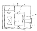
図6は、本発明の第2の実施の形態を示す。本実施の形態のサブクール低温装置は、冷媒保持容器3bにバルブ9a,9b付きの配管8を接続し、配管8に冷却ヘッド4dを接続した構成である。冷凍機1による冷媒液10の冷却を、冷媒保持容器3bから分岐し元に戻る配管8の一部で行う。配管8の一部で冷却された冷媒液10は、密度が高くなるため下方向に降下し、元の容器3bに戻る(自然対流)ため、冷媒液10の冷却を行うことができる。
(Second Embodiment)
FIG. 6 shows a second embodiment of the present invention. The subcool low temperature apparatus of the present embodiment has a configuration in which a pipe 8 with
本実施の形態のメリットは特に、配管8にバルブ9a,9bを設けることによって得られる。すなわち、図6のように、配管8の2箇所にバルブ9a,9bを設けることで、冷媒保持容器3bと、冷却に関与する配管8を切り離すことができる。2つのバルブ9a,9bを閉じ、配管8側(冷凍機1側)の配管内の冷媒液を何らかの方法で排除すると冷凍機1と冷媒保持容器3bとは熱的に分離される。特に配管8をステンレス等の熱伝導率の低い材料のものとした場合は断熱特性が増す。切離した後に冷凍機1を停止すれば、冷媒液10に大きな熱負荷をかけず、冷凍機1の冷却ステージ1aを室温にまで昇温させることが可能で、冷凍機1のメンテナンスを短時間に行うことができる。このような構成でない場合には、冷媒保持容器3b内の冷媒液10をすべて排除して温度を上げなければ冷凍機1のメンテナンスはできないため、メンテナンスに必要な時間が増大し、かつ、被冷却機器20の温度も上昇するため、例えば超電導コイル等では通電ができず、装置の稼動を停止せざるを得ない。
The merit of the present embodiment can be obtained particularly by providing the pipes 8 with
また、本実施の形態では、冷凍機1の設置方向を、低温容器2の側面側から取り付けることができるため、例えば低温容器2の上面に高電圧が加わる構成で上面にアクセスすることが危険な装置においても、危険な場所から離れた位置に冷凍機1が設置できるためメンテナンス性が良い。
Moreover, in this Embodiment, since the installation direction of the
(第3の実施の形態)
図7は、本発明の第3の実施の形態の第1の実施例を示す。この実施例では冷凍機1は、被冷却機器20を収容する低温容器2とは別の断熱真空容器15内に設置し、その間を、断熱配管14で往復接続している。断熱配管14内には冷媒配管11が設けられ、冷媒配管11内には冷媒保持容器3b内の冷媒液10よりも沸点の低い冷媒が気体あるいは超臨界状態として封入されている。冷媒配管11の冷凍機1側には冷却ヘッド4との熱交換部13が設けられ、冷媒保持容器3b側には冷媒液10に浸漬した配管により熱交換部13aが構成されている。また、冷媒配管11の一部に、冷媒の循環を促進する低温循環ポンプ12が設置されている。本実施例によれば、冷凍機1を低温容器2から離れた位置に置くことができ、メンテナンス性に優れたサブクール低温装置を提供することができる。
(Third embodiment)
FIG. 7 shows a first example of the third embodiment of the present invention. In this embodiment, the
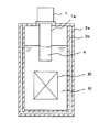
図8は、本発明の第3の実施の形態の第2の実施例を示す。本実施例は、冷媒液10を貯留する冷媒保持容器3bの外側に冷媒配管11を巻き付けて熱交換部13bを構成している。巻き付け方法としては、冷凍機1からの最も温度の低い冷媒の配管を冷媒保持容器3bの下部側から巻き、冷媒液10を冷却しながら温度上昇する冷媒配管11を順次冷媒保持容器3bの上方向に巻き付けていく構成とする。このようにすると、冷媒保持容器3b側面における冷媒配管11の温度勾配と冷媒液10の温度勾配とが一致し、冷媒液10を効率的に冷却し安定性を向上することができる。
FIG. 8 shows a second example of the third embodiment of the present invention. In the present embodiment, the
図9は、本発明の第3の実施の形態の第3実施例を示す。本実施例は、冷媒配管11上の循環ポンプ17を室温部に設け、室温の配管と低温の配管の間に向流熱交換器16を設けた構成である。本実施例ではメンテナンスの必要な循環ポンプ17を室温部に置くことによって、装置のメンテナンス性が向上する。
FIG. 9 shows a third example of the third embodiment of the present invention. In this embodiment, the
1…冷凍機、1a…冷却ステージ、2…低温容器、3a…断熱真空容器、3b…冷媒保持容器、4,4a,4b,4c,4d…冷却ヘッド、5…フィン、6…埋め子、7…ハンドル、8…配管、9a,9b…バルブ、10…冷媒液、11…冷媒配管、12…低温循環ポンプ、13,13a,13b…熱交換部、14…断熱配管、15…断熱真空容器、16…向流熱交換器、17…室温循環ポンプ、20…被冷却機器。
DESCRIPTION OF
Claims (10)
前記配管の前記冷媒保持容器に接続された部分と前記冷却ステージに接続された部分の間に前記冷凍機の停止時に前記冷媒保持容器と冷却に関与する前記配管を切り離すために閉じられるバルブが設けられていることを特徴とするサブクール低温装置。 A refrigerant holding container for storing a refrigerant liquid; a heat insulating vacuum container surrounding the refrigerant holding container; a refrigerator provided with a cooling stage attached to the heat insulating vacuum container and penetrating into the heat insulating vacuum container; the refrigerant holding container; Bei example a pipe and which is cooled by the connected to the refrigerant storage container the cooling stage flowed through the refrigerant liquid in the space between the heat insulating vacuum vessel,
A valve that is closed between the portion of the pipe connected to the refrigerant holding container and the portion connected to the cooling stage to close the refrigerant holding vessel and the pipe involved in cooling is provided when the refrigerator is stopped. A subcool cryogenic device characterized by that.
Priority Applications (1)
| Application Number | Priority Date | Filing Date | Title |
|---|---|---|---|
| JP2006195414A JP4679457B2 (en) | 2006-07-18 | 2006-07-18 | Subcool cryogenic device |
Applications Claiming Priority (1)
| Application Number | Priority Date | Filing Date | Title |
|---|---|---|---|
| JP2006195414A JP4679457B2 (en) | 2006-07-18 | 2006-07-18 | Subcool cryogenic device |
Publications (2)
| Publication Number | Publication Date |
|---|---|
| JP2008025858A JP2008025858A (en) | 2008-02-07 |
| JP4679457B2 true JP4679457B2 (en) | 2011-04-27 |
Family
ID=39116670
Family Applications (1)
| Application Number | Title | Priority Date | Filing Date |
|---|---|---|---|
| JP2006195414A Expired - Fee Related JP4679457B2 (en) | 2006-07-18 | 2006-07-18 | Subcool cryogenic device |
Country Status (1)
| Country | Link |
|---|---|
| JP (1) | JP4679457B2 (en) |
Families Citing this family (12)
| Publication number | Priority date | Publication date | Assignee | Title |
|---|---|---|---|---|
| JP2010038330A (en) * | 2008-08-07 | 2010-02-18 | Kobe Steel Ltd | Hot water bath type vaporizer |
| JP5916517B2 (en) * | 2012-05-29 | 2016-05-11 | 古河電気工業株式会社 | Cooling container |
| EP3279764A4 (en) * | 2015-03-30 | 2018-12-05 | Exascaler Inc. | Electronic-device cooling system |
| EP3279765A4 (en) * | 2015-03-30 | 2018-12-05 | Exascaler Inc. | Electronic-device cooling system |
| JP2016217616A (en) * | 2015-05-20 | 2016-12-22 | 株式会社 フジヒラ | Cryogenic temperature cooling device |
| JP5956100B1 (en) * | 2015-07-02 | 2016-07-20 | 株式会社ExaScaler | Immersion cooling device |
| JP6064083B1 (en) * | 2015-08-31 | 2017-01-18 | 株式会社ExaScaler | Electronic equipment cooling system |
| JP6843343B2 (en) * | 2016-10-26 | 2021-03-17 | 富士平工業株式会社 | Mammalian embryo freezer |
| JP6939034B2 (en) * | 2017-04-05 | 2021-09-22 | 富士通株式会社 | Cooling systems, cooling devices, and electronic systems |
| JP7244747B2 (en) * | 2019-02-28 | 2023-03-23 | 富士通株式会社 | Liquid immersion tank and liquid immersion cooling device |
| JP7299575B2 (en) * | 2019-04-04 | 2023-06-28 | 有限会社北九州メディアシステム | Separable cooling device and cooling method |
| KR102481736B1 (en) * | 2020-09-22 | 2022-12-27 | 주식회사 수퍼제닉스 | A superconducting magnet cooling system for magnetic resonance imaging device |
Citations (6)
| Publication number | Priority date | Publication date | Assignee | Title |
|---|---|---|---|---|
| JPS5986276A (en) * | 1982-11-10 | 1984-05-18 | Hitachi Ltd | Cryostat |
| JPH03114279A (en) * | 1989-09-28 | 1991-05-15 | Toshiba Corp | Cryogenic cooling machine |
| JP2000114030A (en) * | 1998-10-06 | 2000-04-21 | Fuji Electric Co Ltd | Superconducting device |
| JP2001066029A (en) * | 1999-08-25 | 2001-03-16 | Toshiba Corp | Cryogenic cooling system |
| JP2002270913A (en) * | 2001-03-09 | 2002-09-20 | Hitachi Ltd | Superconductive coil unit and mri device |
| JP2005048966A (en) * | 2003-07-29 | 2005-02-24 | Toshiba Corp | Cooling container |
-
2006
- 2006-07-18 JP JP2006195414A patent/JP4679457B2/en not_active Expired - Fee Related
Patent Citations (6)
| Publication number | Priority date | Publication date | Assignee | Title |
|---|---|---|---|---|
| JPS5986276A (en) * | 1982-11-10 | 1984-05-18 | Hitachi Ltd | Cryostat |
| JPH03114279A (en) * | 1989-09-28 | 1991-05-15 | Toshiba Corp | Cryogenic cooling machine |
| JP2000114030A (en) * | 1998-10-06 | 2000-04-21 | Fuji Electric Co Ltd | Superconducting device |
| JP2001066029A (en) * | 1999-08-25 | 2001-03-16 | Toshiba Corp | Cryogenic cooling system |
| JP2002270913A (en) * | 2001-03-09 | 2002-09-20 | Hitachi Ltd | Superconductive coil unit and mri device |
| JP2005048966A (en) * | 2003-07-29 | 2005-02-24 | Toshiba Corp | Cooling container |
Also Published As
| Publication number | Publication date |
|---|---|
| JP2008025858A (en) | 2008-02-07 |
Similar Documents
| Publication | Publication Date | Title |
|---|---|---|
| JP4679457B2 (en) | Subcool cryogenic device | |
| KR102506491B1 (en) | Fault-tolerant cryogenic cooling system | |
| JP4417247B2 (en) | MRI system with superconducting magnet and refrigeration unit | |
| JP4937563B2 (en) | System for cooling a superconducting rotating machine | |
| Mito et al. | Achievement of high heat removal characteristics of superconducting magnets with imbedded oscillating heat pipes | |
| US20180315530A1 (en) | Method and apparatus for cooling a superconducting device immersed in liquid nitrogen | |
| JPH11288809A (en) | Superconducting magnet | |
| US10082549B2 (en) | System and method for cooling a magnetic resonance imaging device | |
| JP5972368B2 (en) | Cooling container | |
| JPS607396B2 (en) | superconducting device | |
| JP5833284B2 (en) | Cooling system | |
| JP5191800B2 (en) | Cooling vessel and superconducting device | |
| WO2014157084A1 (en) | Cooling device for superconductive cable | |
| JP5540642B2 (en) | Cooling device for superconducting equipment | |
| KR102616056B1 (en) | Cooling control device for superconducting fault current limiter | |
| JP6082531B2 (en) | Cooling container | |
| JP2003303713A (en) | Cryogenic device | |
| JP2013245907A (en) | Cooling container | |
| JP5217308B2 (en) | Superconducting part cooling device and its operation method | |
| KR102618452B1 (en) | Cooling apparatus for superconducting fault current limiter | |
| JP2006292319A (en) | Cryostat | |
| JPH0584651B2 (en) | ||
| JPH06163251A (en) | Cryogenic vessel | |
| KR20230139118A (en) | Superconducting current fault limiter with direct cooling structure | |
| JP2009243820A (en) | Cryogenic cooling device |
Legal Events
| Date | Code | Title | Description |
|---|---|---|---|
| A621 | Written request for application examination |
Free format text: JAPANESE INTERMEDIATE CODE: A621 Effective date: 20081017 |
|
| A977 | Report on retrieval |
Free format text: JAPANESE INTERMEDIATE CODE: A971007 Effective date: 20100517 |
|
| A131 | Notification of reasons for refusal |
Free format text: JAPANESE INTERMEDIATE CODE: A131 Effective date: 20100615 |
|
| A521 | Written amendment |
Free format text: JAPANESE INTERMEDIATE CODE: A523 Effective date: 20100806 |
|
| TRDD | Decision of grant or rejection written | ||
| A01 | Written decision to grant a patent or to grant a registration (utility model) |
Free format text: JAPANESE INTERMEDIATE CODE: A01 Effective date: 20110111 |
|
| A01 | Written decision to grant a patent or to grant a registration (utility model) |
Free format text: JAPANESE INTERMEDIATE CODE: A01 |
|
| A61 | First payment of annual fees (during grant procedure) |
Free format text: JAPANESE INTERMEDIATE CODE: A61 Effective date: 20110201 |
|
| FPAY | Renewal fee payment (event date is renewal date of database) |
Free format text: PAYMENT UNTIL: 20140210 Year of fee payment: 3 |
|
| LAPS | Cancellation because of no payment of annual fees |