JP4674206B2 - Improved pump impeller - Google Patents
Improved pump impeller Download PDFInfo
- Publication number
- JP4674206B2 JP4674206B2 JP2006515541A JP2006515541A JP4674206B2 JP 4674206 B2 JP4674206 B2 JP 4674206B2 JP 2006515541 A JP2006515541 A JP 2006515541A JP 2006515541 A JP2006515541 A JP 2006515541A JP 4674206 B2 JP4674206 B2 JP 4674206B2
- Authority
- JP
- Japan
- Prior art keywords
- shroud
- impeller
- dimension
- impeller according
- dimensions
- Prior art date
- Legal status (The legal status is an assumption and is not a legal conclusion. Google has not performed a legal analysis and makes no representation as to the accuracy of the status listed.)
- Expired - Fee Related
Links
Images


Classifications
-
- F—MECHANICAL ENGINEERING; LIGHTING; HEATING; WEAPONS; BLASTING
- F04—POSITIVE - DISPLACEMENT MACHINES FOR LIQUIDS; PUMPS FOR LIQUIDS OR ELASTIC FLUIDS
- F04D—NON-POSITIVE-DISPLACEMENT PUMPS
- F04D29/00—Details, component parts, or accessories
- F04D29/18—Rotors
- F04D29/22—Rotors specially for centrifugal pumps
- F04D29/2261—Rotors specially for centrifugal pumps with special measures
- F04D29/2266—Rotors specially for centrifugal pumps with special measures for sealing or thrust balance
-
- F—MECHANICAL ENGINEERING; LIGHTING; HEATING; WEAPONS; BLASTING
- F04—POSITIVE - DISPLACEMENT MACHINES FOR LIQUIDS; PUMPS FOR LIQUIDS OR ELASTIC FLUIDS
- F04D—NON-POSITIVE-DISPLACEMENT PUMPS
- F04D29/00—Details, component parts, or accessories
- F04D29/08—Sealings
- F04D29/16—Sealings between pressure and suction sides
- F04D29/165—Sealings between pressure and suction sides especially adapted for liquid pumps
- F04D29/167—Sealings between pressure and suction sides especially adapted for liquid pumps of a centrifugal flow wheel
-
- F—MECHANICAL ENGINEERING; LIGHTING; HEATING; WEAPONS; BLASTING
- F04—POSITIVE - DISPLACEMENT MACHINES FOR LIQUIDS; PUMPS FOR LIQUIDS OR ELASTIC FLUIDS
- F04D—NON-POSITIVE-DISPLACEMENT PUMPS
- F04D7/00—Pumps adapted for handling specific fluids, e.g. by selection of specific materials for pumps or pump parts
- F04D7/02—Pumps adapted for handling specific fluids, e.g. by selection of specific materials for pumps or pump parts of centrifugal type
- F04D7/04—Pumps adapted for handling specific fluids, e.g. by selection of specific materials for pumps or pump parts of centrifugal type the fluids being viscous or non-homogenous
-
- F—MECHANICAL ENGINEERING; LIGHTING; HEATING; WEAPONS; BLASTING
- F05—INDEXING SCHEMES RELATING TO ENGINES OR PUMPS IN VARIOUS SUBCLASSES OF CLASSES F01-F04
- F05D—INDEXING SCHEME FOR ASPECTS RELATING TO NON-POSITIVE-DISPLACEMENT MACHINES OR ENGINES, GAS-TURBINES OR JET-PROPULSION PLANTS
- F05D2210/00—Working fluids
- F05D2210/10—Kind or type
- F05D2210/11—Kind or type liquid, i.e. incompressible
-
- F—MECHANICAL ENGINEERING; LIGHTING; HEATING; WEAPONS; BLASTING
- F05—INDEXING SCHEMES RELATING TO ENGINES OR PUMPS IN VARIOUS SUBCLASSES OF CLASSES F01-F04
- F05D—INDEXING SCHEME FOR ASPECTS RELATING TO NON-POSITIVE-DISPLACEMENT MACHINES OR ENGINES, GAS-TURBINES OR JET-PROPULSION PLANTS
- F05D2240/00—Components
- F05D2240/20—Rotors
-
- F—MECHANICAL ENGINEERING; LIGHTING; HEATING; WEAPONS; BLASTING
- F05—INDEXING SCHEMES RELATING TO ENGINES OR PUMPS IN VARIOUS SUBCLASSES OF CLASSES F01-F04
- F05D—INDEXING SCHEME FOR ASPECTS RELATING TO NON-POSITIVE-DISPLACEMENT MACHINES OR ENGINES, GAS-TURBINES OR JET-PROPULSION PLANTS
- F05D2260/00—Function
- F05D2260/60—Fluid transfer
-
- Y—GENERAL TAGGING OF NEW TECHNOLOGICAL DEVELOPMENTS; GENERAL TAGGING OF CROSS-SECTIONAL TECHNOLOGIES SPANNING OVER SEVERAL SECTIONS OF THE IPC; TECHNICAL SUBJECTS COVERED BY FORMER USPC CROSS-REFERENCE ART COLLECTIONS [XRACs] AND DIGESTS
- Y10—TECHNICAL SUBJECTS COVERED BY FORMER USPC
- Y10S—TECHNICAL SUBJECTS COVERED BY FORMER USPC CROSS-REFERENCE ART COLLECTIONS [XRACs] AND DIGESTS
- Y10S415/00—Rotary kinetic fluid motors or pumps
-
- Y—GENERAL TAGGING OF NEW TECHNOLOGICAL DEVELOPMENTS; GENERAL TAGGING OF CROSS-SECTIONAL TECHNOLOGIES SPANNING OVER SEVERAL SECTIONS OF THE IPC; TECHNICAL SUBJECTS COVERED BY FORMER USPC CROSS-REFERENCE ART COLLECTIONS [XRACs] AND DIGESTS
- Y10—TECHNICAL SUBJECTS COVERED BY FORMER USPC
- Y10S—TECHNICAL SUBJECTS COVERED BY FORMER USPC CROSS-REFERENCE ART COLLECTIONS [XRACs] AND DIGESTS
- Y10S416/00—Fluid reaction surfaces, i.e. impellers
-
- Y—GENERAL TAGGING OF NEW TECHNOLOGICAL DEVELOPMENTS; GENERAL TAGGING OF CROSS-SECTIONAL TECHNOLOGIES SPANNING OVER SEVERAL SECTIONS OF THE IPC; TECHNICAL SUBJECTS COVERED BY FORMER USPC CROSS-REFERENCE ART COLLECTIONS [XRACs] AND DIGESTS
- Y10—TECHNICAL SUBJECTS COVERED BY FORMER USPC
- Y10S—TECHNICAL SUBJECTS COVERED BY FORMER USPC CROSS-REFERENCE ART COLLECTIONS [XRACs] AND DIGESTS
- Y10S417/00—Pumps
- Y10S417/90—Slurry pumps, e.g. concrete
Landscapes
- Engineering & Computer Science (AREA)
- Mechanical Engineering (AREA)
- General Engineering & Computer Science (AREA)
- Structures Of Non-Positive Displacement Pumps (AREA)
Description
本発明はインペラに関し、とりわけ遠心力ポンプで用いられるのに適したインペラに関する。 The present invention relates to an impeller, and more particularly to an impeller suitable for use in a centrifugal pump.
一般に、選鉱および浚渫業において、粒状固形物を含む液状混合物を処理するために遠心力ポンプが用いられる。これらのポンプは、フロー中の粒子による過酷なスラリ摩耗を受けやすく、こうした作業に対する相当な経済的な得失をもたらす。この問題を改善しようと、製造業者およびユーザが相当な努力を費やしている。 In general, centrifugal pumps are used in beneficiation and dredging to process liquid mixtures containing particulate solids . These pumps are susceptible to severe slurry wear by particles in the flow, resulting in considerable economic merits and demerits for these tasks. There is considerable effort by manufacturers and users to remedy this problem.
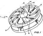
こうした遠心力ポンプは、内部にポンプチャンバを含むポンプハウジングと、回転軸の周りに回転するポンプチャンバ内に配置されたインペラとを有する。インペラは、その一方の面で駆動シャフトに作動可能に連結され、他方の面には吸入口が設けられている。インペラは、駆動シャフトが連結されたハブと、少なくとも1つのシュラウドとを有する。シュラウドの一方の面の上には複数のポンプ翼が設けられる。ポンプ翼は、しばしば2つのシュラウドの間に設けられる。一般に、吸入口に隣接する方のシュラウドを前面シュラウドといい、他方のシュラウドを後面シュラウドという。 Such centrifugal pump has a pump housing containing a pump chamber therein, an impeller disposed in the pump chamber for rotation about an axis of rotation. The impeller is operatively connected to the drive shaft at one side thereof, the suction port is provided on the other surface. The impeller has a hub drive shaft is connected, and at least one shroud. A plurality of pump blades are provided on one side of the shroud. Pump blades are often provided between two shrouds. Generally, the shroud adjacent to the inlet is referred to as a front shroud, and the other shroud is referred to as a rear shroud.
特にスラリを運ぶために用いられる遠心力ポンプは、一般に、シュラウドおよびサイドライナの間の空間内にある流体を回転させやすくするために、ポンプのインペラの後面および前面シュラウド上に設けられたいわゆる「放出」翼または補助翼を利用する。補助翼の形状は、個々の設計者の好みにより異なっていてもよい。 Centrifugal pump used to convey the slurry In particular, generally, in order to facilitate rotating the fluid in the space between the shroud and the side liner provided on the surface and the front shroud after the impeller of the pump so Utilize “emission” wings or auxiliary wings . The shape of the auxiliary blade may Ttei different by preference of the individual designer.
インペラとサイドライナの間の空間にある流体を回転させることにより、遠心力の流れ(渦巻効果)が生じ、インペラの吸入口側の静圧が減少するため、補助翼の間にある流体がインペラの周縁部に向かって流れる。インペラの吐出口と吸入口の間の全体的な推進圧力差により流体はサイドライナの面に沿って流れ落ちる。遠心力が粒子を補助翼の間隙内に引き込む力より大きい場合には、流体内の粒子は同様に間隙から押し出される。 By rotating the fluid in the space between the impeller and the side liner, resulting centrifugal force of the flow (swirl effect), because the static pressure of the suction port side of the impeller is reduced, the fluid located between the aileron impeller It flows toward the peripheral part . Fluid by the overall driving pressure difference between the discharge port and the suction port of the impeller flows down along the surface of the side liner. If the centrifugal force is greater than the force pulling the particles into the auxiliary wing gap, the particles in the fluid will be pushed out of the gap as well .
インペラの前面シュラウドの上の補助翼の主な目的は、推進圧力を抑制して、フローを渦巻き部からインペラの中心へ引き戻す(再循環フロー)ことにある。再循環するフローの速度を低減することにより、インペラおよびこれに係合する吸入口側のサイドライナの摩耗を実質的に低減することができる。 The main purpose of the aileron on the front shroud of the impeller to suppress the driving pressure, pull back the flow to the center of the impeller from the volute portion (recirculation flow) it is in. By reducing the speed of the recirculating flow, the wear of the impeller and the side liner on the inlet side engaged therewith can be substantially reduced .
本願明細書および特許請求の範囲において、文中で特に指定しない限り、次の用語「備える(comprise)」、およびその変形した用語「備えた(comprises)」または「備えている(comprising)」は、明示した整数、ステップ、または整数またはステップのグループを含み、任意の他の整数、ステップ、または整数またはステップのグループを排除しないことを意味すると理解すべきである。 In the present specification and claims, unless otherwise specified in the text, the following terms "comprises (comprise)", and "comprising (Comprises)" deformed term or "comprising (comprising,)" is It should be understood that it includes an explicit integer, step, or group of integers or steps, and does not exclude any other integer, step, or group of integers or steps.
本願明細書中の任意の従来技術への言及は、従来技術がオーストラリアでの一般常識であると示唆または容認するものであると解釈すべきではない。 References to any prior art in this application should not be construed as suggesting or accepting that the prior art is common general knowledge in Australia.
数多くの異なる形状を有する補助翼が、これまでに既存のインペラについて開発され、使用されている。 Aileron with numerous different shapes, so far been developed for existing impeller, it has been used.
特許文献1に記載された1つの具体例において、数多くの放射状の補助翼が利用されており、特許文献1の内容はここに一体のものとして統合される。これらの補助翼は前面シュラウドまたは後面シュラウドの面の上に配置され、環状の突起部が補助翼の周縁部に配置され、隣接する補助翼の間の環状の突起部を通って延びるチャネルが形成されている。
外周部に環状の突起部を有するか否かにかかわらず、補助翼に関する問題は、(翼端渦流に類似の)先端の渦が形成され、粒子が取り込まれると、インペラの周縁部および隣接するサイドライナにおいて局部的に深い窪みを形成するように摩耗し得ることである。 Whether or not having an outer peripheral portion an annular projection portion, the problem with ailerons, a vortex at the tip (similar to wingtip vortices) are formed, the particles are incorporated to the periphery of the impeller and the adjacent it is to be worn so as to form a locally deep recess in the side liner.
部品が摩耗するほど、突出した翼の先に形成される渦流はより大きく、かつ強くなり、隣接したサイドライナの摩耗速度がますます増大する。 As component wear, vortex flow formed in the previous protruding wings larger and stronger, the wear rate of the adjacent side liner is increasingly.
ウォーターポンプは、シュラウドおよび主翼の直径(これらは通常同じ)よりも小さな直径の補助翼を有するものとして知られている。その理由は、摩耗を減らすためではなく、インペラに作用する軸方向の水圧の水力を減らすためである。補助翼の直径は水圧の軸方向の水力の均衡を保たせるような寸法を有する。 Water pump, the shroud and the main wing diameter (these usually the same) are known to have aileron smaller diameter than. The reason is, not for reducing wear is to reduce the hydraulic axial pressure acting on the impeller. The diameter of the ailerons dimensioned so as to keep the balance of axial hydraulic pressure.
本発明の1つの形態によれば、遠心力ポンプで用いられるのに適したインペラが提供され、上記インペラが、遠心力ポンプで用いられるのに適したインペラであって、対向する面、外縁端部、および回転軸を有するシュラウドと、シュラウドの一方の面上にあって、回転軸から離れる方向に延び、外周端を有する複数のポンプ翼と、シュラウドの他方の面上にある複数の補助翼とを備え、各補助翼が外側端を有し、回転軸からシュラウドの外縁端部までの寸法Daが、回転軸から補助翼の外側端までの寸法Dbよりも大きいことを特徴とする。 According to one aspect of the present invention, an impeller suitable for use in the centrifugal pump is provided, the impeller, a impeller suitable for use in centrifugal pumps, the surface facing the outer edge And a shroud having a rotating shaft , a plurality of pump blades on one surface of the shroud extending in a direction away from the rotating shaft and having an outer peripheral end, and a plurality of auxiliary blades on the other surface of the shroud with the door, have each auxiliary blade outer edge, the dimensions Da from the rotation axis to outer edge portion of the shroud, being larger than the dimension Db from the rotation axis to the outer edge of the aileron.
1つの好ましい形態では、インペラは、2つのシュラウド(前面シュラウドおよび後面シュラウド)を有し、これらの間にはポンプ翼が設けられ、一方または両方のシュラウドの上には補助翼が設けられる。1つの実施の形態では、前面シュラウドが補助翼および主ポンプ翼の直径より長い。別の実施の形態では、後面シュラウドが補助翼および主ポンプ翼の直径より長い。さらに別の態様では、前面シュラウドおよび後面シュラウドの両方が、補助翼および主ポンプ翼の直径より長い。好ましくは、ポンプ翼および補助翼の直径は、例えば互いに対して約5%の範囲内でほぼ同じである。 In one preferred form, the impeller includes two shrouds (front shroud and rear face shroud), pump vanes between them are provided, aileron is provided on one or both of the shroud. In one embodiment, the front shroud is longer than the diameter of the auxiliary and main pump blades. In another embodiment, the rear shroud is longer than the diameter of the auxiliary and main pump blades. In yet another embodiment, both the front shroud and the rear face shroud is longer than the diameter of the ailerons and the main pump impeller. Preferably, the pump blade and auxiliary blade diameters are approximately the same, for example within a range of about 5% relative to each other.
好ましくは、ポンプ翼および補助翼は、十分に圧力を低減し、再循環流を抑制するために同等の直径を有するが、インペラのシュラウドはポンプ翼および補助翼の両方より長く延びるものである。 Preferably, the pump blades and auxiliary blades have equivalent diameters to sufficiently reduce pressure and suppress recirculation flow, but the impeller shroud extends longer than both pump blades and auxiliary blades.
シュラウドが長く延びるように構成したインペラに係る利点は、各補助翼から先端渦流が、長く延びたシュラウドの面に沿って流れ落ち、シュラウドと隣接したサイドライナとの間の間隔または空間内に保持されることである。この構成により、インペラおよびライナに対する摩耗が実質的に抑制される。有効な効果は、本発明により先端渦流が完全に形成されることを阻止することよる。 The advantage of the arrangement the impeller as the shroud extends long, the tip vortex from each auxiliary vane, flows down along the surface of the shroud extending long held in interval or space between the side liner adjacent the shroud It is to be done . With this configuration, wear on the impeller and liner are substantially suppressed. An effective effect is to prevent the tip vortex from being completely formed by the present invention.
さらに、本発明の1つの実施の形態では、直径Daのシュラウドを有するインペラが設けられ、直径Dbを有する前面シュラウドの面の上にある主に半径方向に延びる複数の補助翼が設けられ、翼の半径方向の最も外側にある端部は、シュラウドの後方に角度Zで傾斜している。DbがDaの0.95倍より小さいとき、好適にはDbがDaの0.65〜0.95倍の範囲にあるとき、より好適にはDbがDaの0.65〜0.9倍の範囲にあるとき、シュラウド、サイドライナ、および補助翼の摩耗が抑制されることが確認されている。これは、補助翼の先端およびシュラウドの外縁端部の間に、渦流を保持するのに十分な空間があるためであると考えられる。直径Dbは、主ポンプ翼の直径とほぼ等しいことが好ましい。この関係により、主ポンプ翼により生成される圧力に比較して、補助翼による圧力低減機能が実質的に損なわれないようにすることができる。 Furthermore, in one embodiment of the present invention, it is provided an impeller having a shroud of diameter Da, primarily plurality of auxiliary blades extending radially is provided above the surface of the front shroud with a diameter Db, wings The outermost end in the radial direction is inclined at an angle Z behind the shroud . When Db is less than 0.95 times Da , preferably when Db is in the range of 0.65 to 0.95 times Da, more preferably Db is 0.65 to 0.9 times Da. When in range, it has been confirmed that wear of the shroud, side liner, and auxiliary wing is suppressed. This is thought to be because there is sufficient space between the tip of the auxiliary wing and the outer edge of the shroud to hold the vortex . The diameter Db is preferably approximately equal to the diameter of the main pump blade . This relationship can prevent the pressure reducing function of the auxiliary blade from being substantially impaired as compared to the pressure generated by the main pump blade .
本発明の好適な実施形態について、添付図面を参照しながら具体例をもって以下説明する。 Preferred embodiments of the present invention will be described below with specific examples with reference to the accompanying drawings .
図1に示す従来技術によるインペラは、米国特許第4,664,592号において十分に記載されており、その明細書を参照すれば理解される。 Impeller according to the prior art shown in FIG. 1 are well described Oite in U.S. Patent No. 4,664,592, it is understood with reference to the specification.
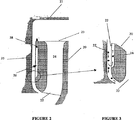
図2に示すように、インペラ20はケーシング・ライナ21の中に収納されている。インペラがケーシング・ライナ21内で回転するとき、スラリは、各ポンピングチャンバ24の吸入口22から吐出口23へインペラ20を通って搬送される。スラリは吐出口23から吸入口22へ自然に再循環し、これにより吸入口側のサイドライナ25が摩耗する。放出翼または補助翼26は、再循環するスラリ27を粒子28で示すようにインペラの吐出口へ戻すよう機能する。インペラ20とサイドライナ25の間に形成されたスラリの流路が図3でより詳細に図示されている。
As is shown in Fig 2, the
図4の写真で明らかな補助翼の摩耗状態は、産業が直面する問題を示すものであり、本発明の実施の形態の態様により改善すべきものである。 The wear state of the aileron apparent in the photograph of FIG. 4 represents a problem faced by the industry and should be improved by aspects of the embodiment of the present invention.
図5は、図2および図3で示す構成部品に対して同様の参照番号を含む。本発明のこの実施の形態では、補助翼はまっすぐであり、Daをシュラウドの直径とすると、補助翼26上の図示されたポイントまでの直径Dbは0.85Daであり、角度Zは45°である。直径Dbは、図5のDcで示す主ポンプ翼の直径とほぼ等しい。
FIG. 5 includes similar reference numbers for the components shown in FIGS. In this embodiment of the present invention, the auxiliary blade is straight, when the Da and the diameter of the shroud, the diameter Db to the illustrated points on
本発明のこの実施の形態について試験を行い、図4に示す従来技術に係る具体例のものと結果を比較すると、ほぼ同じ動作時間において、翼の先端部であってサイドライナに隣接する側面における摩耗が相当に軽減されていることが分かる。 When testing this embodiment of the present invention and comparing the results with that of the prior art example shown in FIG. 4, at the same operating time , on the side of the blade tip adjacent to the side liner . It can be seen that the wear is considerably reduced .
図6の写真から分かるように、これらの従来技術に係るインペラの補助翼上の摩耗は甚大である。 As can be seen from the photograph in FIG. 6, the wear on the auxiliary blades of the impellers according to these prior arts is significant.
これに対して、図7のインペラの補助翼は、同様な期間、同様な環境下で作動させたが、図6に示す補助翼よりもかなりよい状態である。 On the other hand , the auxiliary blade of the impeller of FIG. 7 is operated in the same environment for the same period, but is in a considerably better state than the auxiliary blade shown in FIG.
図8に示す態様のインペラ30は、図5および図7に示す態様のように直線的なものではなく、湾曲した前縁端部および後縁端部を有する補助翼31で形成されている。対応する従来技術の構成は図6に図示されている。また、本発明の態様は、同様な作動時間で従来技術の同等物と比較すると、翼の先端における摩耗がかなり抑制されていることを示す。
The
図9に示す実施形態は、インペラ40の補助翼41に関するさらに別の変形例による形態を示す。
Embodiment shown in FIG. 9 shows an embodiment according to a further modification relates to the
最後に、本発明の精神および範囲から逸脱することなく、さまざまな変形例、修正例、および/または追加例をさまざまな部品の構造および構成に組み込むことができる点を理解されたい。 Finally, it should be understood that various variations, modifications , and / or additional examples may be incorporated into the structure and configuration of various components without departing from the spirit and scope of the present invention.
20 インペラ
22 吸入口
23 吐出口
24 ポンピングチャンバ
25 サイドライナ
26 補助翼
27 再循環スラリ
28 粒子
30 インペラ
31 補助翼
40 インペラ
41 補助翼
20
Claims (15)
対向する面、外縁端部、および回転軸を有するシュラウドと、
シュラウドの一方の面上にあって、回転軸から離れる方向に延び、外周端を有する複数のポンプ翼と、
シュラウドの他方の面上にある複数の補助翼とを備え、
各補助翼が外側端を有し、
回転軸からシュラウドの外縁端部までの寸法Daが、回転軸から補助翼の外側端までの寸法Dbよりも大きく、かつ、回転軸からポンプ翼の外周端までの寸法Dcより大きいことを特徴とするインペラ。An impeller suitable for use in a centrifugal pump for processing a liquid mixture containing particulate solids ,
A shroud having opposing surfaces, outer edge ends, and a rotational axis;
A plurality of pump blades on one side of the shroud , extending in a direction away from the rotation axis and having an outer peripheral end ;
A plurality of ailerons on the other side of the shroud ,
Each aileron has an outer edge;
Feature sizes Da from the rotation axis to outer edge portion of the shroud, rather larger than the dimensions Db from the rotation axis to the outer edge of the aileron, and the larger dimension Dc from the rotation axis to the outer peripheral end of the pump impeller Impeller.
ポンプ翼は、前面シュラウドと後面シュラウドとの間にあり、
補助翼は、一方のシュラウドの他方の面の上にあることを特徴とする請求項2に記載のインペラ。The impeller further includes a rear shroud,
Pump impeller is located between the rear shroud and the front shroud,
The impeller according to claim 2, wherein the auxiliary wing is on the other surface of the one shroud.
ポンプ翼は、前面シュラウドと後面シュラウドとの間にあり、
補助翼は、それぞれのシュラウドの他方の面の上にあることを特徴とする請求項2に記載のインペラ。The impeller further includes a rear shroud,
Pump impeller is located between the rear shroud and the front shroud,
3. An impeller according to claim 2, wherein the aileron is on the other side of each shroud.
Applications Claiming Priority (2)
| Application Number | Priority Date | Filing Date | Title |
|---|---|---|---|
| AU2003903024A AU2003903024A0 (en) | 2003-06-16 | 2003-06-16 | Improved pump impeller |
| PCT/AU2004/000784 WO2004111463A1 (en) | 2003-06-16 | 2004-06-15 | Improved pump impeller |
Related Child Applications (1)
| Application Number | Title | Priority Date | Filing Date |
|---|---|---|---|
| JP2010132224A Division JP2010236555A (en) | 2003-06-16 | 2010-06-09 | Improved pump impeller |
Publications (3)
| Publication Number | Publication Date |
|---|---|
| JP2006527804A JP2006527804A (en) | 2006-12-07 |
| JP2006527804A5 JP2006527804A5 (en) | 2010-03-11 |
| JP4674206B2 true JP4674206B2 (en) | 2011-04-20 |
Family
ID=31954063
Family Applications (2)
| Application Number | Title | Priority Date | Filing Date |
|---|---|---|---|
| JP2006515541A Expired - Fee Related JP4674206B2 (en) | 2003-06-16 | 2004-06-15 | Improved pump impeller |
| JP2010132224A Pending JP2010236555A (en) | 2003-06-16 | 2010-06-09 | Improved pump impeller |
Family Applications After (1)
| Application Number | Title | Priority Date | Filing Date |
|---|---|---|---|
| JP2010132224A Pending JP2010236555A (en) | 2003-06-16 | 2010-06-09 | Improved pump impeller |
Country Status (23)
| Country | Link |
|---|---|
| US (1) | US7329085B2 (en) |
| EP (1) | EP1633983B2 (en) |
| JP (2) | JP4674206B2 (en) |
| KR (1) | KR101036567B1 (en) |
| CN (1) | CN100482948C (en) |
| AP (1) | AP1938A (en) |
| AR (1) | AR044693A1 (en) |
| AU (2) | AU2003903024A0 (en) |
| BR (1) | BRPI0411553B1 (en) |
| CA (1) | CA2521506C (en) |
| EA (1) | EA007331B1 (en) |
| ES (1) | ES2621192T5 (en) |
| IL (1) | IL171110A (en) |
| JO (1) | JO2510B1 (en) |
| MX (1) | MXPA05013304A (en) |
| MY (1) | MY139037A (en) |
| PE (1) | PE20050024A1 (en) |
| PL (1) | PL1633983T5 (en) |
| PT (1) | PT1633983T (en) |
| UA (1) | UA84873C2 (en) |
| UY (1) | UY28365A1 (en) |
| WO (1) | WO2004111463A1 (en) |
| ZA (1) | ZA200509318B (en) |
Families Citing this family (29)
| Publication number | Priority date | Publication date | Assignee | Title |
|---|---|---|---|---|
| DE602006003074D1 (en) | 2005-03-16 | 2008-11-20 | Weir Minerals Africa Proprieta | WHEEL FOR A CENTRIFUGAL PUMP |
| JP4017003B2 (en) * | 2005-09-30 | 2007-12-05 | ダイキン工業株式会社 | Centrifugal fan and air conditioner using the same |
| WO2008038306A2 (en) * | 2006-09-28 | 2008-04-03 | Weir Minerals India Private Limited | An improved ceramic integral vanes impeller |
| EP2117672B1 (en) * | 2007-02-02 | 2013-01-23 | Donaldson Company, Inc. | Air filtration media pac |
| US8439642B2 (en) * | 2007-06-01 | 2013-05-14 | The Gorman-Rupp Company | Pump and pump impeller |
| US8545589B2 (en) * | 2007-06-26 | 2013-10-01 | Donaldson Company, Inc. | Filtration media pack, filter element, and methods |
| JP5118951B2 (en) * | 2007-12-11 | 2013-01-16 | 新明和工業株式会社 | Centrifugal pump impeller and centrifugal pump |
| US9808752B2 (en) * | 2008-02-04 | 2017-11-07 | Donaldson Company, Inc. | Method and apparatus for forming fluted filtration media |
| PL2331826T3 (en) | 2008-05-27 | 2016-07-29 | Weir Minerals Australia Ltd | Improvements relating to centrifugal pump impellers |
| US20100032365A1 (en) * | 2008-08-06 | 2010-02-11 | Ted Anthony Moe | Z-media having flute closures, methods and apparatus |
| NO334954B1 (en) * | 2012-11-12 | 2014-08-04 | Agr Subsea As | Centrifugal pump impeller and its use in pumping drilling fluid containing drill cuttings |
| RU2688066C2 (en) * | 2014-04-23 | 2019-05-17 | Зульцер Мэнэджмент Аг | Impeller for centrifugal pump, centrifugal pump, as well as its use |
| EA033362B1 (en) * | 2014-09-15 | 2019-10-31 | Weir Minerals Australia Ltd | Slurry pump impeller |
| WO2016040979A1 (en) * | 2014-09-15 | 2016-03-24 | Weir Minerals Australia Ltd | Slurry pump impeller |
| JP6374744B2 (en) * | 2014-09-26 | 2018-08-15 | 株式会社久保田鉄工所 | Water pump with impeller |
| KR101720491B1 (en) * | 2015-01-22 | 2017-03-28 | 엘지전자 주식회사 | Centrifugal Fan |
| US11136983B2 (en) | 2016-11-10 | 2021-10-05 | Wayne/Scott Fetzer Company | Dual inlet volute, impeller and pump housing for same, and related methods |
| USD868117S1 (en) | 2017-04-05 | 2019-11-26 | Wayne/Scott Fetzer Company | Pump component |
| USD986287S1 (en) | 2017-04-05 | 2023-05-16 | Wayne/Scott Fetzer Company | Pump component |
| JP2018178820A (en) * | 2017-04-10 | 2018-11-15 | 日本電産サンキョー株式会社 | Pump device |
| CN107100888B (en) * | 2017-05-23 | 2023-06-16 | 中交疏浚技术装备国家工程研究中心有限公司 | Twisted blade type impeller of large-pass spherical-diameter efficient double-shell mud pump |
| AU2018348789A1 (en) | 2017-10-12 | 2021-06-17 | Weir Minerals Australia Ltd | Inlet component for a slurry pump |
| JP2019120224A (en) * | 2018-01-10 | 2019-07-22 | 株式会社荏原製作所 | Impeller for pump, casing for pump and pump |
| EP3830420A4 (en) * | 2018-08-01 | 2022-08-24 | Weir Slurry Group, Inc. | Inverted annular side gap arrangement for a centrifugal pump |
| CN111089077B (en) * | 2018-10-24 | 2024-08-09 | 汉江弘源襄阳碳化硅特种陶瓷有限责任公司 | Wear-resistant silicon carbide ceramic impeller |
| CN109505775A (en) * | 2019-01-04 | 2019-03-22 | 浙江大元泵业股份有限公司 | A kind of multistage cutting pump |
| CN114017354B (en) * | 2021-11-01 | 2022-06-14 | 合肥天秤检测科技有限公司 | Underground is visited thing and is used muddy water extraction equipment based on energy-efficient motor |
| USD978919S1 (en) * | 2021-11-18 | 2023-02-21 | Scd Co., Ltd. | Impeller for pump |
| CN114607613A (en) * | 2022-02-11 | 2022-06-10 | 江苏大学 | Multistage semi-open type centrifugal pump capable of reducing abrasion |
Family Cites Families (21)
| Publication number | Priority date | Publication date | Assignee | Title |
|---|---|---|---|---|
| GB117558A (en) | 1917-11-16 | 1918-07-25 | Adolf Ewald Gull | Improvement in Centrifugal Pumps. |
| GB272713A (en) | 1926-08-04 | 1927-06-23 | Drysdale & Co Ltd | Improvements in centrifugal pumps |
| US1881723A (en) * | 1929-07-15 | 1932-10-11 | Harry S Lee | Pump |
| US1879803A (en) * | 1930-01-27 | 1932-09-27 | Andrew G Johnson | Rotary pump |
| US1869803A (en) | 1930-05-21 | 1932-08-02 | Jr Will J Ecker | Cardcase and method of manufacture |
| GB896366A (en) | 1959-11-16 | 1962-05-16 | Klein Schanzlin & Becker Ag | Centrifugal pump |
| GB930474A (en) * | 1960-01-19 | 1963-07-03 | Res & Dev Pty Ltd | Improvements in centrifugal pumps and the like |
| US3190226A (en) * | 1963-09-13 | 1965-06-22 | Thomas E Judd | Centrifugal pumps |
| US3384026A (en) * | 1966-08-16 | 1968-05-21 | Itt | Pump apparatus |
| US3663117A (en) * | 1970-01-21 | 1972-05-16 | Cornell Mfg Co | Aeration pump |
| JPS5113001U (en) * | 1974-07-16 | 1976-01-30 | ||
| SU1064047A2 (en) | 1982-02-18 | 1983-12-30 | Предприятие П/Я М-5841 | Centrifugal pump |
| GB2143285B (en) * | 1983-07-14 | 1987-11-11 | Warman Int Ltd | Centrifugal impeller |
| US4613281A (en) | 1984-03-08 | 1986-09-23 | Goulds Pumps, Incorporated | Hydrodynamic seal |
| US4883403A (en) * | 1986-10-07 | 1989-11-28 | Warman International Limited | Impellers for centrifugal pumps |
| US5165858A (en) * | 1989-02-24 | 1992-11-24 | The Carborundum Company | Molten metal pump |
| JPH0610603A (en) | 1992-04-23 | 1994-01-18 | Praxair Technol Inc | Stress reducing type radial flow impeller blade |
| US5489187A (en) * | 1994-09-06 | 1996-02-06 | Roper Industries, Inc. | Impeller pump with vaned backplate for clearing debris |
| AUPN143795A0 (en) * | 1995-03-01 | 1995-03-23 | Sykes Pumps Australia Pty Limited | Centrifugal pump |
| US6036434A (en) * | 1995-10-06 | 2000-03-14 | Roper Holdings, Inc. | Aeration system |
| US7179057B2 (en) * | 2004-03-31 | 2007-02-20 | Weir Slurry Group, Inc. | Velocity profile impeller vane |
-
2003
- 2003-06-16 AU AU2003903024A patent/AU2003903024A0/en not_active Abandoned
-
2004
- 2004-05-30 JO JO200468A patent/JO2510B1/en active
- 2004-06-11 PE PE2004000584A patent/PE20050024A1/en active IP Right Grant
- 2004-06-14 AR ARP040102057A patent/AR044693A1/en active IP Right Grant
- 2004-06-15 MX MXPA05013304A patent/MXPA05013304A/en active IP Right Grant
- 2004-06-15 US US10/560,463 patent/US7329085B2/en not_active Expired - Lifetime
- 2004-06-15 WO PCT/AU2004/000784 patent/WO2004111463A1/en active Search and Examination
- 2004-06-15 CA CA2521506A patent/CA2521506C/en not_active Expired - Lifetime
- 2004-06-15 AU AU2004247750A patent/AU2004247750B2/en not_active Expired
- 2004-06-15 EP EP04736829.5A patent/EP1633983B2/en not_active Expired - Lifetime
- 2004-06-15 EA EA200600039A patent/EA007331B1/en unknown
- 2004-06-15 KR KR1020057019441A patent/KR101036567B1/en not_active IP Right Cessation
- 2004-06-15 AP AP2005003410A patent/AP1938A/en active
- 2004-06-15 PT PT47368295T patent/PT1633983T/en unknown
- 2004-06-15 MY MYPI20042297A patent/MY139037A/en unknown
- 2004-06-15 BR BRPI0411553-8B1A patent/BRPI0411553B1/en active IP Right Grant
- 2004-06-15 UA UAA200600336A patent/UA84873C2/en unknown
- 2004-06-15 UY UY28365A patent/UY28365A1/en not_active Application Discontinuation
- 2004-06-15 PL PL04736829T patent/PL1633983T5/en unknown
- 2004-06-15 CN CNB2004800121655A patent/CN100482948C/en not_active Expired - Lifetime
- 2004-06-15 ES ES04736829T patent/ES2621192T5/en not_active Expired - Lifetime
- 2004-06-15 JP JP2006515541A patent/JP4674206B2/en not_active Expired - Fee Related
-
2005
- 2005-09-26 IL IL171110A patent/IL171110A/en not_active IP Right Cessation
- 2005-11-17 ZA ZA200509318A patent/ZA200509318B/en unknown
-
2010
- 2010-06-09 JP JP2010132224A patent/JP2010236555A/en active Pending
Also Published As
Similar Documents
| Publication | Publication Date | Title |
|---|---|---|
| JP4674206B2 (en) | Improved pump impeller | |
| JP2006527804A5 (en) | ||
| US8568095B2 (en) | Reduced tip clearance losses in axial flow fans | |
| CN109257934B (en) | Rotating part for a thick matter pump | |
| JPS58104400A (en) | Device for reducing abrasion of cavitation | |
| CA2961066C (en) | Slurry pump impeller | |
| JP3841391B2 (en) | Turbo machine | |
| JP2004353655A (en) | Radial impeller | |
| JP5558183B2 (en) | Turbo machine | |
| WO2008082397A1 (en) | Reduced tip clearance losses in axial flow fans | |
| JP2001073993A (en) | Centrifugal fluid machinery | |
| CA2839472C (en) | Improvements to pumps and components therefor | |
| JP6509372B2 (en) | Blower and vacuum cleaner equipped with the same | |
| JP6758924B2 (en) | Impeller | |
| JP6523917B2 (en) | Centrifugal pump | |
| US11236763B2 (en) | Inverted annular side gap arrangement for a centrifugal pump | |
| JP2004183630A (en) | Vortex pump | |
| CN113039365A (en) | Vortex pump | |
| JP2004197738A (en) | Advanced diffuser for centrifugal compressor | |
| JP2020197143A (en) | Impeller and multistage pump | |
| JPH05248385A (en) | Swirl impeller | |
| KR20050039029A (en) | Structure for protecting backflow of sirroco fan |
Legal Events
| Date | Code | Title | Description |
|---|---|---|---|
| A621 | Written request for application examination |
Free format text: JAPANESE INTERMEDIATE CODE: A621 Effective date: 20070111 |
|
| RD03 | Notification of appointment of power of attorney |
Free format text: JAPANESE INTERMEDIATE CODE: A7423 Effective date: 20070111 |
|
| A131 | Notification of reasons for refusal |
Free format text: JAPANESE INTERMEDIATE CODE: A131 Effective date: 20090901 |
|
| A601 | Written request for extension of time |
Free format text: JAPANESE INTERMEDIATE CODE: A601 Effective date: 20091124 |
|
| A602 | Written permission of extension of time |
Free format text: JAPANESE INTERMEDIATE CODE: A602 Effective date: 20091201 |
|
| A601 | Written request for extension of time |
Free format text: JAPANESE INTERMEDIATE CODE: A601 Effective date: 20100104 |
|
| A602 | Written permission of extension of time |
Free format text: JAPANESE INTERMEDIATE CODE: A602 Effective date: 20100112 |
|
| A524 | Written submission of copy of amendment under article 19 pct |
Free format text: JAPANESE INTERMEDIATE CODE: A524 Effective date: 20100121 |
|
| A02 | Decision of refusal |
Free format text: JAPANESE INTERMEDIATE CODE: A02 Effective date: 20100209 |
|
| A01 | Written decision to grant a patent or to grant a registration (utility model) |
Free format text: JAPANESE INTERMEDIATE CODE: A01 |
|
| A61 | First payment of annual fees (during grant procedure) |
Free format text: JAPANESE INTERMEDIATE CODE: A61 Effective date: 20110124 |
|
| R150 | Certificate of patent or registration of utility model |
Free format text: JAPANESE INTERMEDIATE CODE: R150 |
|
| FPAY | Renewal fee payment (event date is renewal date of database) |
Free format text: PAYMENT UNTIL: 20140128 Year of fee payment: 3 |
|
| R250 | Receipt of annual fees |
Free format text: JAPANESE INTERMEDIATE CODE: R250 |
|
| LAPS | Cancellation because of no payment of annual fees |