JP4674146B2 - Coreless motor - Google Patents
Coreless motor Download PDFInfo
- Publication number
- JP4674146B2 JP4674146B2 JP2005302580A JP2005302580A JP4674146B2 JP 4674146 B2 JP4674146 B2 JP 4674146B2 JP 2005302580 A JP2005302580 A JP 2005302580A JP 2005302580 A JP2005302580 A JP 2005302580A JP 4674146 B2 JP4674146 B2 JP 4674146B2
- Authority
- JP
- Japan
- Prior art keywords
- housing
- magnet holder
- fitted
- rotating shaft
- disposed
- Prior art date
- Legal status (The legal status is an assumption and is not a legal conclusion. Google has not performed a legal analysis and makes no representation as to the accuracy of the status listed.)
- Expired - Fee Related
Links
Images


Description
本発明は、コアレスモータに関し、特にマグネットホルダをハウジング内に固定した構成のコアレスモータに関する。 The present invention relates to a coreless motor, and more particularly to a coreless motor having a configuration in which a magnet holder is fixed in a housing.
特許文献1には、モータの回転軸の両端をハウジングの内部に固定したボトム側軸受けとヘッド側軸受けとで回転自在に支持することが開示されている。 Japanese Patent Application Laid-Open No. H10-228561 discloses that a motor is supported rotatably by a bottom-side bearing and a head-side bearing in which both ends of a rotating shaft of the motor are fixed inside the housing.
この特許文献1に記載のモータは、コアードモータ(回転軸に設けた鉄芯にコイルが巻かれている)であるが、ハウジングはボトム側軸受けの装着部分を外側に突設して形成している。 The motor described in Patent Document 1 is a cored motor (a coil is wound around an iron core provided on a rotating shaft), but a housing is formed by protruding a mounting portion of a bottom bearing outward. .
コアレスモータにおいても、特許文献1と同様に、ハウジングはボトム側軸受けの装着部分を外側に突設して形成したものが公知である。 Also in the coreless motor, similarly to Patent Document 1, a housing is known in which a mounting portion of a bottom bearing protrudes outward.
しかし、上述した従来技術においては、マグネットホルダをハウジングのボトム中央部に嵌め込んでいるため、ボトム中央部の外側への突設量を所定量とらないと、マグネットホルダを安定に装着できないおそれがある。そのため、ハウジングのボトム中央部の突設量が多くなり、しかも回転軸の寸法がその突設量だけ不要に長くなるため、モータの小型化に限界があった。 However, in the above-described prior art, since the magnet holder is fitted into the bottom center portion of the housing, there is a possibility that the magnet holder cannot be stably mounted unless the projecting amount to the outside of the bottom center portion is a predetermined amount. is there. For this reason, the amount of protrusion at the center of the bottom of the housing increases, and the size of the rotating shaft becomes unnecessarily long by the amount of protrusion, which limits the miniaturization of the motor.
そこで、本発明は、モータの小型化を図ると共にマグネットホルダの安定装着が可能なコアレスモータの提供を目的とする。 Accordingly, an object of the present invention is to provide a coreless motor capable of downsizing the motor and stably mounting the magnet holder.
前記課題を解決するために、請求項1に記載された発明は、ハウジングと、ハウジング内に配置された回転軸と、回転軸に固定され且つ回転軸と一体に回転する円筒状のコイル体と、コイル体の内周側に配置されたマグネット及びマグネットホルダと、ハウジングのボトム側に配置され回転軸のボトム側端を回転自在に保持するボトム側軸受けと、ハウジングのヘッド側に配置され回転軸のヘッド側端を回転自在に保持するヘッド側軸受けとを備え、ハウジングのボトムにはボトム面の中央部を外側から内側に凹ませてハウジング内部に向けて突設し、マグネットホルダの内周側が嵌合する被嵌合部が設けてあり、被嵌合部の凹みは底面を有し、この凹みの底面にはハウジング内側にボトム側軸受けを当接配置してあり、マグネットホルダはハウジング内においてハウジングボトムの被嵌合部に嵌合すると共にボトム側軸受けを係止していることを特徴とする。 In order to solve the above-mentioned problem, the invention described in claim 1 includes a housing, a rotating shaft disposed in the housing, a cylindrical coil body fixed to the rotating shaft and rotating integrally with the rotating shaft. A magnet and a magnet holder arranged on the inner peripheral side of the coil body, a bottom bearing arranged on the bottom side of the housing to rotatably hold the bottom side end of the rotating shaft, and a rotating shaft arranged on the head side of the housing A head-side bearing that rotatably holds the head side end of the housing, and the bottom of the housing is recessed from the outside to the inside with the center of the bottom surface protruding toward the inside of the housing, and the inner circumference side of the magnet holder is Yes and the fitted portion is provided to be fitted, the fitted portion recess has a bottom surface, the bottom surface of the recess Yes in abutment disposed bottom side bearing on the housing inner magnet holder Characterized in that it locks the bottom bearing thereby fitted into the fitting portion of the housing bottom within Ujingu.
請求項2に記載された発明は、請求項1に記載の発明において、ハウジングボトムの被嵌合部にはハウジングの外面が凹んだ凹部をキャップで塞いであることを特徴とする。 The invention described in claim 2 is characterized in that, in the invention described in claim 1, the fitted portion of the housing bottom is formed by closing a recessed portion in which the outer surface of the housing is recessed with a cap.
請求項1に記載の発明によれば、ハウジングにおいて、マグネットホルダとの被嵌合部をハウジングの内側に突設させているから、ハウジングの外側への出っ張りが無いのでモータ外形の小型化を図ることができる。また、マグネットホルダとの被嵌合部をハウジングの内側に突設させているので、その分従来よりも回転軸を短くでき、回転軸の重量を軽減することによりモータ全体の重量を軽減できる。 According to the first aspect of the present invention, in the housing, since the portion to be fitted with the magnet holder protrudes from the inside of the housing, there is no protrusion to the outside of the housing, so that the motor outer shape is reduced. be able to. Further, since the portion to be fitted with the magnet holder protrudes from the inside of the housing, the rotation shaft can be made shorter than the conventional one, and the weight of the rotation shaft can be reduced to reduce the weight of the entire motor.
また、マグネットホルダとの被嵌合部をハウジングの内側に突設させているから、マグネットホルダとの嵌合量を長く取ってもモータ外形寸法の制約を受け難く、設計の自由度が高いと共にマグネットホルダとの嵌合量を長くとることによりマグネットホルダの取付け強度を高めることができ、マグネットホルダを安定に装着できる。また、マグネットホルダの取付け強度が高いので、耐衝撃性に優れる。 In addition, since the mating part with the magnet holder protrudes from the inside of the housing, it is difficult to be restricted by the external dimensions of the motor even if the fitting amount with the magnet holder is long, and the degree of freedom in design is high. By taking a long fitting amount with the magnet holder, the mounting strength of the magnet holder can be increased, and the magnet holder can be mounted stably. Moreover, since the attachment strength of the magnet holder is high, the shock resistance is excellent.
被嵌合部におけるマグネットホルダとの嵌合量を長くとって取付け強度を高めることにより、マグネットホルダの振れや位置ズレを低減して、マグネットとコイル体との接触を防止でき、スムーズな駆動で且つ長寿命のコアレスモータを得ることができる。 By increasing the amount of fitting with the magnet holder in the mated part to increase the mounting strength, the magnet holder can be prevented from swinging and misaligned to prevent contact between the magnet and the coil body, with smooth drive. In addition, a long-life coreless motor can be obtained.
請求項2に記載された発明によれば、請求項1に記載の発明と同様の効果を奏すると共に、ハウジングのボトム外面の凹部における塵や水溜まりを防止できる。 According to the second aspect of the present invention, the same effects as those of the first aspect of the invention can be achieved, and dust and water pools in the recesses on the bottom outer surface of the housing can be prevented.
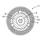
以下に、添付図面を参照して、本発明の実施の形態を詳細に説明する。図1は本実施の形態に係るコアレスモータの縦断面図であり、図2は図1のA−A断面図であり、図3はハウジングのみを取り出して示すA−A断面図である。 Embodiments of the present invention will be described below in detail with reference to the accompanying drawings. 1 is a longitudinal sectional view of a coreless motor according to the present embodiment, FIG. 2 is a sectional view taken along the line AA in FIG. 1, and FIG. 3 is a sectional view taken along the line AA showing only the housing.
本実施の形態に係るコアレスモータ1は、電動機械の動力源に用いられるモータであり、ハウジング3と、回転軸5と、コイル体7と、マグネット9と、マグネットホルダ11とを備えている。
A coreless motor 1 according to the present embodiment is a motor used as a power source of an electric machine, and includes a
ハウジング3はプレス成形により有底円筒形状に形成されており、開口側(ヘッド側)にはヘッドカバーアッセンブリ13が取付けられている。ヘッドカバーアッセンブリ13には、ヘッド側軸受け15及び給電端子17が取付けられている。
The
ハウジング3のボトム19には、半径方向中央部の外面を外側から内側に凹ませてハウジング3の内部に向けて突設した被嵌合部21が設けてある。被嵌合部21にはハウジング3のボトム19の中央部を僅かに外側に突設した形状にして、回転軸5のボトム側端5aとの間に空隙Sを形成している。
The
尚、ハウジング3の内周面には磁性体できた円筒状スリーブ27が嵌合してあり、ハウジング周面の磁性体の厚みを厚くして、磁気漏れを防止している。
A
また、ハウジング3のボトム19には被嵌合部21による外面の凹み33を塞ぐキャップ31が装着されている。
Further, a
回転軸5はボトム側に設けたボトム側軸受け23とヘッド側に設けたヘッド側軸受け15とにより回転自在に保持されている。回転軸5のヘッド側端にはアダプタ25が取付けられており、アダプタ25から回転出力が外部機構に伝達される。
The rotating
ボトム側軸受け23はハウジング3の被嵌合部21に当接配置してあると共にマグネットホルダ11に形成された係止部35に係止されて、被嵌合部21とマグネットホルダ11とで嵌合固定してある。
The bottom bearing 23 is disposed in contact with the fitted
コイル体7は円筒形状に形成されており、且つマグネット9の外周側にマグネット9と隙間をあけて配置されている。コイル体7は回転軸5に固定してあり、回転軸5と共に回転するようになっている。尚、コイル体7にはブラシ28から整流子24を経て給電されている。
The
マグネット9はマグネットホルダ11の外周に固定されている。マグネットホルダ11は、略円筒形状を成し、ボトム側端部の内周径を小さくした段部29が形成されている。マグネットホルダ11のボトム側端部はハウジング3のボトム19の内面に当接し、且つ段部29で被嵌合部21の外周面に嵌合している。
The
次に、本実施の形態に係るコアレスモータ1の作用及び効果を説明する。コアレスモータ1の組立て時には、マグネット9を外周に固定したマグネットホルダ11のボトム側に設けた係止部35にボトム側軸受け23を係止し、マグネットホルダ11のボトム側をハウジング3に形成した被嵌合部21に嵌合することによりハウジング3内に装着する。そして、コイル体7を固定した回転軸5のボトム側端部をボトム側軸受け23に挿通した後、ヘッドカバーアッセンブリを回転軸5のヘッド側に装着してハウジング3に固定する。
Next, the operation and effect of the coreless motor 1 according to the present embodiment will be described. When the coreless motor 1 is assembled, the bottom bearing 23 is locked to the
コアレスモータの駆動は、ブラシ28に電流を給電すると、ブラシ28に摺接する整流子24からコイル体7に給電され、マグネット9とコイル体7との間に生じる電磁力によりコイル体7が回転軸5と共に回転する。
When a current is supplied to the
本実施の形態に係るコアレスモータ1によれば、ハウジング3には、マグネットホルダ11との被嵌合部21をハウジング3の内側に突設形成しているから、外側に突設する場合に比較してハウジング3の回転軸方向の長さを短くでき、コアレスモータ1の小型化を図ることができる。
According to the coreless motor 1 according to the present embodiment, the
マグネットホルダ11との被嵌合部21をハウジング3の内側に突設させているので、その分回転軸5の寸法を短くして回転軸5の重量を軽減でき、コアレスモータ全体の重量を軽減できる。
Since the fitted
マグネットホルダ11との被嵌合部21をハウジング3の内側に突設させているから、マグネットホルダ11との嵌合量を長く取っても回転軸方向の寸法の制約を受け難く、設計の自由度が高いと共にマグネットホルダ11及び回転軸5の取付け強度を高めることができる。このように、マグネットホルダ11及び回転軸5の取付け強度を高めることにより、耐衝撃性を高めることができる。尚、本実施の形態に係るコアレスモータ1の耐衝撃実験をおこなったところ、10Gの衝撃を加えた場合にも回転軸5の傾き異常が無かった。
Since the
特に、マグネットホルダ11と被嵌合部21との嵌合量を長くとることにより、マグネットホルダ11及び回転軸5の振れや位置ズレを低減できるから、マグネット9とコイル体7との接触を防止でき、スムーズで長寿命のモータ駆動を得ることができる。
In particular, by making the fitting amount between the
ハウジング3の被嵌合部21に対応する凹み33をキャップ31で塞いでいるので、ハウジング外面に形成された凹みに塵や水溜まりが生じるのを防止できる。
Since the
ハウジング3の周面に磁性体スリーブ27を配置しているので、ハウジング3の肉厚を薄くすることができる。
Since the
ハウジング3の内周面に磁性体スリーブ27を装着することにより、ハウジング3の外周面に装着する場合に比較して、磁性体スリーブ27とハウジング3との間に水等が入り込むことを防止でき、錆や錆汁の発生を防止できると共に溶接等の接合手段が不要にできる。
By attaching the
本発明は上述した実施の形態に限定されず、その要旨を逸脱しない範囲で種々変形可能である。 The present invention is not limited to the above-described embodiments, and various modifications can be made without departing from the scope of the invention.
被嵌合部21は突設形状を円柱にすることに限らず、角柱状にしてもよく、形状は制限されない。
The to-be-fitted
また、被嵌合部21は複数設けてもよい。
A plurality of fitted
1 コアレスモータ
3 ハウジング
5 回転軸
7 コイル体
9 マグネット
11 マグネットホルダ
15 ヘッド側軸受け
21 被嵌合部
23 ボトム側軸受け
31 キャップ
DESCRIPTION OF SYMBOLS 1
Claims (2)
A housing, a rotating shaft disposed in the housing, a cylindrical coil body fixed to the rotating shaft and rotating integrally with the rotating shaft, a magnet and a magnet holder disposed on the inner peripheral side of the coil body, and a housing A bottom side bearing that is disposed on the bottom side of the rotary shaft and rotatably supports the bottom side end of the rotary shaft, and a head side bearing that is disposed on the head side of the housing and rotatably holds the head side end of the rotary shaft. the projected toward the inside housing bottom to the recessed inward central portion of the bottom surface from the outside, Yes and the fitted portion is provided with an inner circumferential side of the magnet holder is fitted, the fitted portion recess has a bottom surface, this is the bottom surface of the recess Yes in abutment disposed bottom side bearing on the housing inner magnet holder match fitted in the fitted portion of the housing bottom in the housing Coreless motor, characterized in that it locks the bottom bearing with.
Priority Applications (1)
| Application Number | Priority Date | Filing Date | Title |
|---|---|---|---|
| JP2005302580A JP4674146B2 (en) | 2005-10-18 | 2005-10-18 | Coreless motor |
Applications Claiming Priority (1)
| Application Number | Priority Date | Filing Date | Title |
|---|---|---|---|
| JP2005302580A JP4674146B2 (en) | 2005-10-18 | 2005-10-18 | Coreless motor |
Publications (3)
| Publication Number | Publication Date |
|---|---|
| JP2007116763A JP2007116763A (en) | 2007-05-10 |
| JP2007116763A5 JP2007116763A5 (en) | 2008-10-16 |
| JP4674146B2 true JP4674146B2 (en) | 2011-04-20 |
Family
ID=38098442
Family Applications (1)
| Application Number | Title | Priority Date | Filing Date |
|---|---|---|---|
| JP2005302580A Expired - Fee Related JP4674146B2 (en) | 2005-10-18 | 2005-10-18 | Coreless motor |
Country Status (1)
| Country | Link |
|---|---|
| JP (1) | JP4674146B2 (en) |
Families Citing this family (2)
| Publication number | Priority date | Publication date | Assignee | Title |
|---|---|---|---|---|
| KR101558563B1 (en) * | 2008-07-28 | 2015-10-08 | 엘지이노텍 주식회사 | Step Actuator |
| JP5270735B2 (en) * | 2011-09-13 | 2013-08-21 | トヨタ自動車株式会社 | Rotating electric machine and power transmission device |
Citations (1)
| Publication number | Priority date | Publication date | Assignee | Title |
|---|---|---|---|---|
| JPH0560159U (en) * | 1992-01-14 | 1993-08-06 | セイコー電子工業株式会社 | Cylindrical coreless motor for vibration |
-
2005
- 2005-10-18 JP JP2005302580A patent/JP4674146B2/en not_active Expired - Fee Related
Patent Citations (1)
| Publication number | Priority date | Publication date | Assignee | Title |
|---|---|---|---|---|
| JPH0560159U (en) * | 1992-01-14 | 1993-08-06 | セイコー電子工業株式会社 | Cylindrical coreless motor for vibration |
Also Published As
| Publication number | Publication date |
|---|---|
| JP2007116763A (en) | 2007-05-10 |
Similar Documents
| Publication | Publication Date | Title |
|---|---|---|
| TWI362163B (en) | Motor | |
| KR100361410B1 (en) | Dc motor | |
| WO2015004795A1 (en) | Motor device | |
| JP4674146B2 (en) | Coreless motor | |
| JP6200972B2 (en) | Motor with reduction mechanism | |
| JP2008206737A (en) | Washing machine | |
| JP2010048353A (en) | Clutch mechanism, reduction gear with clutch, and motor with reduction gear | |
| CN113016125A (en) | Rotor, motor, and method for manufacturing rotor | |
| JP2006304558A (en) | Hypocycloid speed reducer built in motor | |
| JP2013110880A (en) | Electric motor | |
| JP2009022147A (en) | Core for axial motor, stator and axial motor | |
| JP4367415B2 (en) | Electric tool | |
| JP2009131078A (en) | Electric motor | |
| JP2010074880A (en) | Stepping motor | |
| JP2007116765A (en) | Motor | |
| JP2009072032A (en) | Dc motor and electric tool with same | |
| JP6375422B2 (en) | Motor with reduction mechanism | |
| JP2018182908A (en) | Rotary electric machine | |
| JP4464697B2 (en) | Electric motor | |
| JP5129726B2 (en) | Motor with reduction mechanism | |
| JP2018161055A (en) | Motor with speed reduction mechanism | |
| JP3843097B2 (en) | Coreless motor | |
| JP4366788B2 (en) | Motor with linear drive mechanism | |
| JP4630177B2 (en) | Torque limiter | |
| JP6531205B2 (en) | Motor with speed reduction mechanism |
Legal Events
| Date | Code | Title | Description |
|---|---|---|---|
| A521 | Written amendment |
Free format text: JAPANESE INTERMEDIATE CODE: A523 Effective date: 20080828 |
|
| A621 | Written request for application examination |
Free format text: JAPANESE INTERMEDIATE CODE: A621 Effective date: 20080901 |
|
| A977 | Report on retrieval |
Free format text: JAPANESE INTERMEDIATE CODE: A971007 Effective date: 20100917 |
|
| A131 | Notification of reasons for refusal |
Free format text: JAPANESE INTERMEDIATE CODE: A131 Effective date: 20100928 |
|
| A521 | Written amendment |
Free format text: JAPANESE INTERMEDIATE CODE: A523 Effective date: 20101111 |
|
| TRDD | Decision of grant or rejection written | ||
| A01 | Written decision to grant a patent or to grant a registration (utility model) |
Free format text: JAPANESE INTERMEDIATE CODE: A01 Effective date: 20110111 |
|
| A01 | Written decision to grant a patent or to grant a registration (utility model) |
Free format text: JAPANESE INTERMEDIATE CODE: A01 |
|
| A61 | First payment of annual fees (during grant procedure) |
Free format text: JAPANESE INTERMEDIATE CODE: A61 Effective date: 20110124 |
|
| R150 | Certificate of patent or registration of utility model |
Free format text: JAPANESE INTERMEDIATE CODE: R150 |
|
| FPAY | Renewal fee payment (event date is renewal date of database) |
Free format text: PAYMENT UNTIL: 20140128 Year of fee payment: 3 |
|
| LAPS | Cancellation because of no payment of annual fees |