JP4674094B2 - Stereoscopic observation device - Google Patents
Stereoscopic observation device Download PDFInfo
- Publication number
- JP4674094B2 JP4674094B2 JP2005034753A JP2005034753A JP4674094B2 JP 4674094 B2 JP4674094 B2 JP 4674094B2 JP 2005034753 A JP2005034753 A JP 2005034753A JP 2005034753 A JP2005034753 A JP 2005034753A JP 4674094 B2 JP4674094 B2 JP 4674094B2
- Authority
- JP
- Japan
- Prior art keywords
- imaging
- optical system
- stereoscopic
- unit
- eye
- Prior art date
- Legal status (The legal status is an assumption and is not a legal conclusion. Google has not performed a legal analysis and makes no representation as to the accuracy of the status listed.)
- Expired - Fee Related
Links
Images


Description
本発明は、たとえば外科手術、特に脳神経外科や、耳鼻科咽喉科、整形・形成外科、産婦人科、あるいは眼科などにおいて有効な、医療用としての立体観察装置に関する。 The present invention relates to a three-dimensional observation apparatus for medical use that is effective in, for example, surgery, particularly neurosurgery, otolaryngology, plastic surgery, obstetrics and gynecology, or ophthalmology.
たとえば脳神経外科等においては、微細な術部の拡大観察を行うために手術用顕微鏡が使用されている。脳のように微細な組織からなる器官は、構造組織を肉眼で識別することが困難であるために、器官の処置は顕微鏡下で行われている。
脳神経外科の手術は、ごく狭い領域で行われるばかりでなく、血管や神経等の非常に重要で、かつデリケートな組織を対象としている。それらの観察だけでなく、実際に血管相互や神経相互を繋いだり、血管や神経を避けて腫瘍等を取り除く処置が行われる。そのため、手術用顕微鏡は観察対象を拡大観察するだけでなく、処置を行うために観察対象を立体的に捉えられる立体視を行えることが、重要な機能として要求される。
For example, in neurosurgery and the like, a surgical microscope is used to perform a magnified observation of a fine surgical site. Since organs composed of minute tissues such as the brain are difficult to distinguish structural tissues with the naked eye, the treatment of the organs is performed under a microscope.
Neurosurgery surgery is not only performed in a very small area, but also targets very important and delicate tissues such as blood vessels and nerves. In addition to these observations, treatments that actually connect blood vessels and nerves or remove tumors by avoiding blood vessels and nerves are performed. Therefore, it is required as an important function that the surgical microscope not only magnifies and observes the observation target but also can perform stereoscopic viewing so that the observation target can be captured in three dimensions in order to perform treatment.
しかしながら、従来から用いられる立体視顕微鏡は、顕微鏡の接眼レンズを直接肉眼で覗くように設計されているため、術者は手術を行っている間、常に接眼レンズを覗いていて、顔の位置が固定され非常にわずらわしいという問題があった。
そこで、この覗き込むわずらわしさを取り除いた顕微鏡として、たとえば[特許文献1]や[特許文献2]あるいは[特許文献3]等に記載されるような医療用観察システムが開示されるに至った。
However, conventional stereo microscopes are designed to look directly into the eyepiece of the microscope with the naked eye, so the operator always looks into the eyepiece while performing surgery and the face position is There was a problem that it was fixed and very annoying.
Therefore, a medical observation system described in, for example, [Patent Document 1], [Patent Document 2], or [Patent Document 3] has been disclosed as a microscope that eliminates the troublesomeness of peeping.
[特許文献1]に開示されている手術用顕微鏡は、対物レンズと、右左両目用の変倍光学系と、各変倍光学系からの光束を撮像して立体映像信号を生成する電子撮像素子を内蔵した鏡体部を備え、この鏡体部で生成された立体映像信号を液晶モニターで立体表示する。これにより、術者は接眼部を覗き込むことなく、テレビを観ている感覚で術部の立体拡大観察を行うことができる。
[特許文献2]に開示されている立体観察装置は、右左両目用の撮像光学系を有し、これら左右両目の映像信号を生成する独立した鏡体部からの左右の映像信号を、それぞれ術者の前方に配置されたレンズ作用のあるパネル(例えば、フレネルレンズ)に投影する左右の投影装置から構成される。
The surgical microscope disclosed in [Patent Document 1] includes an objective lens, a variable magnification optical system for both right and left eyes, and an electronic image pickup device that generates a stereoscopic video signal by imaging light beams from the variable magnification optical systems. The 3D video signal generated by the mirror unit is stereoscopically displayed on a liquid crystal monitor. Thereby, the surgeon can perform the stereoscopic enlargement observation of the operation part as if watching the television without looking into the eyepiece.
The stereoscopic observation apparatus disclosed in [Patent Document 2] has an imaging optical system for right and left eyes, and uses left and right video signals from independent mirror units that generate video signals for both left and right eyes. It is comprised from the right and left projection apparatus which projects on the panel (for example, Fresnel lens) with a lens action arrange | positioned ahead of the person.
術者は、パネルに投影された左右それぞれの映像を、左右それぞれの目で別々に観察することにより、接眼部を覗き込むことなく、テレビを観ている感覚で術部の立体観察を行うことができる。また、鏡体部とパネルが独立しているので、鏡体部の動きに合わせてパネルが移動することがなく、術者の姿勢は制限されない。
[特許文献3]に開示されているモニター付きスタンド装置は、医療用顕微鏡を支持するスタンド装置であって、医療用顕微鏡付近にCTやMRIによる断層画像を表示可能なモニター装置が支持されていることを特徴としている。
これにより、重量物である医療用顕微鏡を希望する空間位置に支持することができ、医療用顕微鏡付近にモニター装置を備えることで、術者は手術中において、手術を中断することなく断層画像の確認を行うことができ、作業効率の向上を得られる。
The stand device with a monitor disclosed in [Patent Document 3] is a stand device that supports a medical microscope, and a monitor device that can display a tomographic image by CT or MRI is supported near the medical microscope. It is characterized by that.
As a result, the medical microscope, which is a heavy object, can be supported in a desired spatial position, and by providing a monitor device in the vicinity of the medical microscope, the operator can perform tomographic image capture without interruption during the operation. Confirmation can be made and work efficiency can be improved.
ところで、上述の[特許文献1]では、[特許文献3]で開示される手術用顕微鏡に対して、撮像素子により観察像を撮像し、接眼鏡筒部分を立体表示が可能な液晶モニターに置き換えた構成をしている。
この種の技術では、実際に液晶モニターを観察しようとすると、接眼鏡筒を覗き込む場合に比べて術者の顔を手術用顕微鏡から放す必要がある。そのため、術者が無理のない姿勢で観察を行える位置に液晶モニターを配置しようとすると、液晶モニターから張り出した鏡体部が、[特許文献3]のものに比べて術部に近づいてしまう。これにより、術部周りの作業空間が減少し、処置具等が鏡体部に干渉する不具合の生じる虞れがある。
By the way, in the above-mentioned [Patent Document 1], an observation image is picked up by an imaging device with respect to the surgical microscope disclosed in [Patent Document 3], and the eyepiece tube portion is replaced with a liquid crystal monitor capable of stereoscopic display. It has a configuration.
In this type of technology, when actually observing the liquid crystal monitor, it is necessary to release the operator's face from the surgical microscope as compared to when looking into the eyepiece tube. Therefore, when the liquid crystal monitor is arranged at a position where the surgeon can observe with a reasonable posture, the mirror body part protruding from the liquid crystal monitor approaches the surgical part as compared with that in [Patent Document 3]. As a result, the work space around the surgical site is reduced, and there is a risk that a treatment instrument or the like may interfere with the mirror body.
また、[特許文献2]の立体観察装置は、術部の観察像を撮像する鏡体部と、パネルとが別体に構成されている。そのため、パネルに対して鏡体部を独立して移動ができ、術者は鏡体部の位置によらず好みの位置にパネルを配置できる。
しかしながら、実際に観察の行い易いパネル位置は術部近傍になるため、鏡体部がパネルと術者の間に配置され、あるいはパネルと術部の間に配置されている。そのため、鏡体部は観察の邪魔になることがあり、手術の作業空間が十分に確保できずに、処置具が撮像部に干渉する虞れがある。
Further, in the stereoscopic observation apparatus of [Patent Document 2], a mirror part that captures an observation image of an operation part and a panel are configured separately. Therefore, the mirror part can be moved independently with respect to the panel, and the surgeon can place the panel at a preferred position regardless of the position of the mirror part.
However, since the panel position that is actually easy to observe is in the vicinity of the surgical site, the body portion is disposed between the panel and the surgeon, or is disposed between the panel and the surgical site. For this reason, the mirror unit may interfere with observation, and there is a possibility that the treatment tool may interfere with the imaging unit without sufficiently securing a working space for surgery.
さらに、この立体観察装置は、パネルに対して右目用と左目用の映像を投影装置から投影することによって立体映像を作り出しているため、術者の頭上、もしくは後方に投影装置が設置されている。このとき、パネルと投影装置の関係は1対1であり、立体観察が行える術者の位置に関しても自由度は少ない。
術者が観察方向や観察位置を変更するためにパネルの位置を移動させると、同時に投影装置も移動する。特にパネルの表示角度を変更するには、投影装置はパネルを中心とし、パネルと投影装置との間の距離を半径とする円運動を行うため、術者の周辺には広いスペースが必要になるという問題がある。
Furthermore, since this stereoscopic observation apparatus creates a stereoscopic image by projecting right-eye and left-eye images from the projection device onto the panel, the projection device is installed above or behind the surgeon. . At this time, there is a one-to-one relationship between the panel and the projection device, and the degree of freedom is small with respect to the position of the operator who can perform stereoscopic observation.
When the operator moves the position of the panel in order to change the observation direction or the observation position, the projection apparatus also moves at the same time. In particular, in order to change the display angle of the panel, the projection apparatus performs a circular motion with the panel as the center and the distance between the panel and the projection apparatus as a radius, so a large space is required around the operator. There is a problem.
本発明は、前記事情に鑑みなされたものであり、その目的とするところは、術者にとって観察の行い易い位置に配置しても、良好な視野が確保されるようになり、また、術部と立体表示装置との間に十分な作業スペースを確保でき、わずかなスペースで立体表示パネルの表示面の角度を変更できる立体観察装置を提供しようとするものである。 The present invention has been made in view of the above circumstances, and it is an object may be placed on the observation of the performed easily position for the surgeon, becomes so that good viewing is ensured, also operative part It is an object of the present invention to provide a stereoscopic observation apparatus that can secure a sufficient work space between the stereoscopic display device and the angle of the display surface of the stereoscopic display panel in a small space.
上述の目的を達成するために、請求項1の発明は、互いに同一の撮像対象物を撮像する第1の撮像光学系および第2の撮像光学系を備え、前記撮像対象物を立体撮像する立体撮像手段と、
前記立体撮像手段によって撮像された像を立体表示する立体表示手段と、
前記立体表示手段と前記立体撮像手段とを保持する保持手段と、
を備え、
前記第1の撮像光学系および第2の撮像光学系は、それぞれ撮像対象物からの像を取り込む開口領域を有し、前記第1の撮像光学系の第1の開口領域の位置と前記第2の撮像光学系の第2の開口領域の位置とが間隔をあけて配置され、前記第1の開口領域には該第1の開口領域から取り込む前記撮像対象物の第1の像の光軸方向を変更する第1の光軸方向変更手段を設け、前記第2の開口領域には該第2の開口領域から取り込む前記撮像対象物の第2の像の光軸方向を変更する第2の光軸方向変更手段を設け、
更に、前記第1の光軸方向変更手段および前記第2の光軸方向変更手段の位置の変更もしくは光軸方向を変更する角度を変更することで前記立体撮像手段から前記撮像対象物までの距離の変更に応じて撮像対象物からの像を取り込む第1の撮像光学系の入射軸と第2の撮像光学系の入射軸とがなす内向角を変更して撮像対象物に合わせて前記第1の撮像光学系と第2の撮像光学系の焦点距離を調節可能な焦点距離変更手段を設けたことを特徴とする立体観察装置である。
To achieve the above object, the invention of claim 1, comprising a first imaging optical system and the second imaging optical system for imaging the same imaging object from each other, stereoscopic imaging the imaged object stereoscopic Imaging means;
Stereoscopic display means for stereoscopically displaying an image captured by the stereoscopic imaging means;
Holding means for holding the stereoscopic display means and the stereoscopic imaging means ;
With
Each of the first imaging optical system and the second imaging optical system has an aperture area for capturing an image from the imaging target, and the position of the first aperture area of the first imaging optical system and the second The position of the second aperture region of the imaging optical system is arranged at an interval, and the optical axis direction of the first image of the imaging object captured from the first aperture region in the first aperture region And a second light for changing the optical axis direction of the second image of the imaging object captured from the second opening area in the second opening area. Axial direction changing means is provided,
Further, the distance from the stereoscopic imaging means to the imaging object by changing the position of the first optical axis direction changing means and the second optical axis direction changing means or changing the angle of changing the optical axis direction. The inward angle formed by the incident axis of the first imaging optical system that captures an image from the imaging target and the incident axis of the second imaging optical system is changed in accordance with the change of the first imaging optical system according to the imaging target. The stereoscopic observation apparatus is characterized in that a focal length changing means capable of adjusting the focal length of the imaging optical system and the second imaging optical system is provided .
請求項2の発明は、請求項1に記載の立体観察装置において、前記焦点距離変更手段は、撮像対象物に対する前記立体撮像手段の距離の変更に応じて前記第1の撮像光学系と第2の撮像光学系の焦点距離をピントの合う値に調節するとき、撮像対象物からの像を取り込む第1の撮像光学系の入射軸と、同撮像対象物からの像を取り込む第2の撮像光学系の入射軸とがなす内向角を一定に維持するように前記第1の撮像光学系と第2の撮像光学系の焦点距離を調節することを特徴とする。According to a second aspect of the present invention, in the stereoscopic observation apparatus according to the first aspect, the focal length changing unit is configured to change the first imaging optical system and the second imaging unit according to a change in the distance of the stereoscopic imaging unit with respect to the imaging target. When adjusting the focal length of the imaging optical system to a value that is in focus, the incident axis of the first imaging optical system that captures an image from the imaging object and the second imaging optical that captures an image from the imaging object The focal lengths of the first imaging optical system and the second imaging optical system are adjusted so that the inward angle formed by the incident axis of the system is kept constant.
請求項3の発明は、請求項1または請求項2に記載の立体観察装置において、前記第1の光軸方向変更手段で変更した光軸と、前記第2の光軸方向変更手段で変更した光軸とが同軸になるように対向して保持されることを特徴とする。According to a third aspect of the present invention, in the stereoscopic observation apparatus according to the first or second aspect, the optical axis changed by the first optical axis direction changing unit and the second optical axis direction changing unit are changed. The optical axis is held so as to be coaxial with each other.
請求項4の発明は、請求項1乃至3のいずれかの請求項に記載の立体観察装置において、前記立体撮像手段は、前記立体表示手段の背面部に位置して該立体表示手段に取り付けられることを特徴とする。According to a fourth aspect of the present invention, in the stereoscopic observation apparatus according to any one of the first to third aspects, the stereoscopic imaging unit is attached to the stereoscopic display unit so as to be positioned on the back surface of the stereoscopic display unit. It is characterized by that.
請求項5の発明は、請求項1乃至4のいずれかの請求項に記載の立体観察装置において、前記立体表示手段は、立体表示手段の位置および傾斜角度を調整自在な支持手段に支持されることを特徴とする。According to a fifth aspect of the present invention, in the stereoscopic observation apparatus according to any one of the first to fourth aspects, the stereoscopic display means is supported by a support means capable of adjusting a position and an inclination angle of the stereoscopic display means. It is characterized by that.
請求項6の発明は、前記保持手段は、請求項1乃至5のいずれかの請求項に記載の立体観察装置において、前記立体表示手段と前記立体撮像手段とを一体に保持することを特徴とする。The invention of
請求項7の発明は、請求項1記載の立体観察装置において、前記第1の撮像光学系と前記第2の撮像光学系は、それぞれ対物光学系と結像光学系と撮像素子を含み、前記第1の撮像光学系と前記第2の撮像光学系は、それぞれの対物光学系を通過する光軸が同軸になるように保持されることを特徴とする。A seventh aspect of the present invention is the stereoscopic observation apparatus according to the first aspect, wherein the first imaging optical system and the second imaging optical system include an objective optical system, an imaging optical system, and an imaging element, respectively. The first imaging optical system and the second imaging optical system are characterized in that the optical axes passing through the respective objective optical systems are held so as to be coaxial.
本発明によれば、撮像部が術空間に与える影響を最小限に抑制し、良好な視野と十分な作業空間を確保することができる等の効果を奏する。 According to the present invention, it is possible to minimize the influence of the imaging unit on the operation space, and to obtain an effect such as ensuring a good visual field and a sufficient work space.
以下、図面を参照して本発明の実施の形態に係る、医療用としての立体観察装置について説明する。
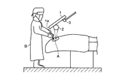
はじめに、本発明における第1の実施の形態を、図1ないし図3にもとづいて説明する。図1は手術中での医療用立体観察装置の外観斜視図、図2は手術中での医療用立体観察装置の一部側面図、図3は医療用立体観察装置要部を切欠した背面図である。
図1および図2に示すように、立体観察装置は、液晶モニター(立体表示手段)1と、この液晶モニター1の背面側に一体的に取付けられ、かつ内部に後述する撮像光学系(立体撮像手段)6を収容保持する撮像部(保持手段)2と、前記液晶モニター1をボールジョイント3を介して支持する支持脚(支持手段)4とから構成される。前記撮像光学系6は、術部Aの撮像をなし、この撮像信号は液晶モニター1へ送られて、術部Aの映像が立体的に表示されるようになっている。
A medical stereoscopic observation apparatus according to an embodiment of the present invention will be described below with reference to the drawings.
First, a first embodiment of the present invention will be described with reference to FIGS. FIG. 1 is an external perspective view of a medical stereoscopic observation apparatus during surgery, FIG. 2 is a partial side view of the medical stereoscopic observation apparatus during surgery, and FIG. 3 is a rear view in which a main part of the medical stereoscopic observation apparatus is cut away. It is.
As shown in FIGS. 1 and 2, the stereoscopic observation apparatus is a liquid crystal monitor (stereoscopic display means) 1 and an imaging optical system (stereoscopic imaging) that is integrally attached to the back side of the liquid crystal monitor 1 and is described later. Means) The image pickup section (holding means) 2 that accommodates and holds 6 and the support leg (support means) 4 that supports the liquid crystal monitor 1 via the ball joint 3 are configured. The imaging
前記支持脚4は、液晶モニター1を3次元的に自由な位置に移動し、かつその位置で固定可能に構成されている。しかも、液晶モニター1はボールジョイント3を介して支持脚4と連結されるため、液晶モニター1の位置が定まった状態で、液晶モニター1の面傾斜角度を自由に設定できる。これらの操作は、液晶モニター1の側面に設けられるグリップ7を把持することで容易に行える。また、グリップ7には後述するように変倍操作のためのスイッチ8が設けられている。
つぎに、前記撮像部2と、この撮像部2に収容保持される撮像光学系6について、図3にもとづいて詳述する。
前記撮像部2は、左右の両側端面が閉塞される円筒体状をなし、その周壁一部が軸方向に沿って液晶モニター1の背面に一体に取付け固定される。撮像部2の軸方向における略中央部には所定の間隔を存して一対の開口部9,10が設けられている。図における右側の開口部を左目用開口部9と呼び、左側の開口部を右目用開口部10と呼ぶ。これら左右目開口部9,10にはそれぞれガラスが嵌め込まれて、内部を密封状態にしている。
The
Next, the
The
撮像部2内における左目用開口部9と対向する位置に、左目用ミラー(第1の光軸変更手段)11が配置され、さらにこのミラー11の反射側に所定間隔を存して、左目用対物レンズ(対物光学系)12と、左目用変倍光学系13と、左目用結像レンズ(結像光学系)14および、左目用撮像素子15が配置され、これらで第1の撮像光学系6Aが構成される。
また撮像部2内には、右目用開口部10と対向する位置に、右目用ミラー(第2の光軸変更手段)16が配置され、さらにこのミラー16の反射側に所定間隔を存して、右目用対物レンズ(対物光学系)17と、右目用変倍光学系18と、右目用結像レンズ(結像光学系)19および、右目用撮像素子20が配置され、これらで第2の撮像光学系6Bが構成される。
A left-eye mirror (first optical axis changing means) 11 is disposed at a position facing the left-
In the
そして、左目用ミラー11から左目用撮像素子15までの第1の撮像光学系6Aの光軸と、右目用ミラー16から右目用撮像素子20までの第2の撮像光学系6Bの光軸とが、同軸になるように左右対称に配置されている。
このようにして構成される医療用立体観察装置であって、術者Bはグリップ7を把持して、撮像部2が術部Aを撮像できるとともに、術者Bが観察し易い位置に、液晶モニター1を移動操作する。
このとき、術者Bは術部Aを直接観察しているのと同じ感覚で観察が行える位置に、前記液晶モニター1を配置する。いずれにしても、液晶モニター1は術部Aと術者Bの間に配置されることになり、液晶モニター1を見上げるなど、術部Aから離れた位置に視線を向ける必要がない。
The optical axis of the first imaging
The medical stereoscopic observation apparatus configured as described above, in which the operator B holds the
At this time, the operator B arranges the liquid crystal monitor 1 at a position where observation can be performed with the same feeling as directly observing the surgical site A. In any case, the liquid crystal monitor 1 is disposed between the surgical site A and the surgeon B, and it is not necessary to direct the line of sight to a position away from the surgical site A, such as looking up at the liquid crystal monitor 1.
また、術者Bにとって、液晶モニター1の背面部は全くの死角になる。そして、液晶モニター1の背面部に設けられる撮像部2は、液晶モニター1の表面面積よりも小さいから、術者Bは撮像部2の存在を感じないですむ。
つぎに、術者Bは術部Aの観察を行う。立体視するために必要な左目用の術部Aの像(第1の像)は、左目用開口部9を介して撮像部2内部に入り、左目用ミラー11で反射されて進行方向が変る。そして、左目用対物レンズ12および左目用変倍光学系13を通って左目用結像レンズ14で結像され、左目用撮像素子15によって撮像されて左目用の映像信号となる。
Further, for the surgeon B, the back surface of the liquid crystal monitor 1 becomes a completely blind spot. And since the
Next, the surgeon B observes the surgical site A. An image (first image) of the left-eye surgical part A necessary for stereoscopic viewing enters the
右目用の術部Aの像(第2の像)は、右目用開口部10を介して撮像部2の中に入り、右目用ミラー16で反射されて進行方向が変る。そして、右目用対物レンズ17、右目用変倍光学系18を通って右目用結像レンズ19で結像され、右目用撮像素子20によって撮像されて右目用の映像信号となる。
これら左右の映像信号は、図示しないカメラコントロールユニット(以下、CCUと呼ぶ)に送られる。このCCUにおいて、術部Aの像が左目用ミラー11および右目用ミラー16によって反射されることで反転した像を、さらに反転させる。したがって、CCUは立体映像として液晶モニター1に映像信号を送信でき、この映像信号により液晶モニター1は術部Aを立体表示し、術者Bは術部Aの立体観察が可能となる。
The image (second image) of the right-eye surgical part A enters the
These left and right video signals are sent to a camera control unit (hereinafter referred to as CCU) (not shown). In this CCU, the image that is inverted by the image of the surgical site A being reflected by the left-
つぎに、術者Bは術部Aの処置を行う。術者Bは処置具C,Dである、たとえば電気メスや吸引管等を用いて処置を行う。このとき、特に図2に示すように、液晶モニター1の下端縁1aと術部Aの間には十分なスペースが形成されており、液晶モニター1や撮像部2との干渉を気にすることなく、余裕をもって手術を行うことができる。
手術の継続中において、術者Bが特に重要であると感じたら、ただちにスイッチ8を押せばよい。これにより、図示しない駆動機構が作動して、左目用変倍光学系13および右目用変倍光学系18を構成するレンズ保持用のレンズ枠を移動させる。したがって、レンズの位置関係が変更されて、液晶モニター1に表示される観察像がさらに拡大化することになる。
Next, the surgeon B performs treatment for the surgical site A. The surgeon B performs treatment using the treatment tools C and D, for example, an electric knife or a suction tube. At this time, as shown in FIG. 2 in particular, a sufficient space is formed between the
If the operator B feels particularly important during the operation, the
以上説明した医療用立体観察装置によれば、術者Bにとって死角となる領域である液晶モニター1の背面部に撮像部2を備えた。しかも、この撮像部2においては、左右の光軸を同軸上に対称的に配置することで、液晶モニター1の背面からの張り出し量を最小限に抑制し、処置作業において充分な空間スペースを確保できる。
なお、この実施の形態においては、撮像部2を術者の死角となる液晶モニター1の背面部に備えたが、これに限定されるものではなく、撮像部2を液晶モニター1の下面部に備えてもよい。
さらに、この実施の形態においては、立体表示装置として液晶モニター1を用いたが、これに代って、たとえばプロジェクターを備え、パネルに投影する形式のものであってもよい。撮像部2内に変倍光学系13,18を内蔵したが、これに代って、たとえば電子ズームを用いれば変倍光学系が不用となり、撮像部をさらに小型化することができる。光軸方向変更手段としてミラー11,16を用いたが、プリズムであってもよい。
According to the medical stereoscopic observation apparatus described above, the
In this embodiment, the
Further, in this embodiment, the liquid crystal monitor 1 is used as the stereoscopic display device. However, instead of this, for example, a projector may be provided and projected onto a panel. Although the variable magnification
つぎに、本発明における第2の実施の形態を、図4ないし図6にもとづいて説明する。なお、第1の実施の形態と同一構成部品については同番号を付して新たな説明は省略する。
図4は医療用立体観察装置要部を切欠した背面図、図5は左右のミラー11,16の位置を移動して焦点距離を変動する焦点距離変更機構(焦点距離変更手段:位置移動手段)Kを説明する図4の矢印H方向から見た図、図6はミラー11,16の動作説明図である。
医療用立体観察装置として、液晶モニター1と、この液晶モニター1の背面側に一体的に取付けられ撮像光学系6を収容保持する撮像部2と、前記液晶モニター1とボールジョイント3を介して支持する支持脚4とからなる基本構成については何らの変更もない。
Next, a second embodiment of the present invention will be described with reference to FIGS. Note that the same components as those in the first embodiment are denoted by the same reference numerals, and a new description is omitted.
4 is a rear view in which the main part of the medical stereoscopic observation apparatus is cut away, and FIG. 5 is a focal length changing mechanism that changes the focal length by moving the positions of the left and right mirrors 11 and 16 (focal length changing means: position moving means). FIG. 6 is a diagram for explaining the operation of the
As a medical stereoscopic observation apparatus, supported by a liquid crystal monitor 1, an
ここでは、左目用のミラー11と左目用変倍光学系13との間に、複数のレンズ群で構成され、各レンズ群の位置関係を変更することにより焦点距離を変更できる左目用対物光学系32が設けられる。同様に、右目用のミラー16と右目用変倍光学系18との間には、複数のレンズ群で構成され、各レンズ群の位置関係を変更することにより焦点距離を変更できる右目用対物光学系33が設けられている。
前記撮像光学系6において、第1の撮像光学系6Aの左目用ミラー11には、光束の反射中心である中心Fの位置に紙面とは直交する方向に回転軸21が設けられる。第2の撮像光学系6Bの右目用ミラー16には、光束の反射中心である中心Gの位置に紙面とは直交する方向に回転軸22が設けられる。
Here, a left-eye objective optical system that includes a plurality of lens groups between the left-
In the imaging
そして、撮像部2内部には、中心Fと中心Gを結ぶ線と平行に形成されるガイド溝23を備えた支持台24が配置される。前記回転軸21には左目用ナット部25が接続され、軸22には右目用ナット部26が接続される。これら左目・右目用ナット部25,26には、互いに逆向きのネジ孔が設けられており、それぞれのネジ孔にリードネジ27に設けられる雄ネジ部27a,27bが螺合している。
前記リードネジ27は、前記ガイド溝23と平行に設けられていて、ここに形成される雄ネジ部27a,27bは互いに逆向きである。リードネジ27の一端部には歯車28が取付けられ、この近傍に配置されるモータ30の回転軸に取付けられる歯車31と噛合している。前記モータ30は、図示しないコントロールボックスに電気的に接続され、ここから制御信号を受けるようになっていて、これらで焦点距離変更機構Kが構成される。
A
The
なお、これら左目用対物光学系32と右目用対物光学系33に対するレンズ群の位置関係を変更する手段の駆動源として、先に説明したモータ30を兼用させる。あるいは、別途、駆動機構および駆動源を備えるようにしてもよい。
このようにして構成される医療用立体観察装置であって、術者Bはグリップ7を把持して、撮像部2が術部Aを撮像できるとともに、術者Bが観察し易い位置に、液晶モニター1を移動操作する。
つぎに、術者Bは術部Aの観察を行う。立体視するために必要な左目用の術部Aの像は、左目用開口部9を介して撮像部2内部に入り、左目用ミラー11で反射される。そして、左目用対物光学系32および左目用変倍光学系13を通って左目用結像レンズ14で結像され、左目用撮像素子15によって撮像されて左目用の映像信号となる。
The
The medical stereoscopic observation apparatus configured as described above, in which the operator B holds the
Next, the surgeon B observes the surgical site A. An image of the left-eye surgical part A necessary for stereoscopic viewing enters the
右目用の術部Aの像は、右目用開口部10を介して撮像部2の中に入り、右目用ミラー16で反射される。そして、右目用対物光学系33および右目用変倍光学系18を通って右目用結像レンズ19で結像され、右目用撮像素子20によって撮像されて右目用の映像信号となる。左右の映像信号はCCUに送られ、ここで反転した映像信号を立体映像として生成し、液晶モニター1へ送信する。この映像信号により液晶モニター1は術部Aを立体表示し、術者Bは術部Aの立体観察が可能となる。
つぎに、術者Bは術部Aの処置を行う。このとき、術部Aと撮像部2との距離が変わる場合の作用について、図5および図6を用いて説明する。
術者Bは、術部Aと撮像部2との間が、距離Iの位置で処置を開始するものとする。この状態で、左目用ミラー11と右目用ミラー16および、左目用対物光学系32と右目用対物光学系33は実線で示された位置にあり、撮像光学系6の内向角はθ1となる。
The image of the surgical part A for the right eye enters the
Next, the surgeon B performs treatment for the surgical site A. At this time, an operation when the distance between the surgical part A and the
It is assumed that the surgeon B starts treatment at a distance I between the surgical section A and the
処置を進めて行くにしたがって術部Aは徐々に深い位置に変り、術部Aと撮像部2の間隔は距離Jになる。そのままではピントがずれた映像になってしまうので、術者Bはスイッチ8を押す。
スイッチ8からの信号はコントロールボックスへ送信され、ここから左目用対物光学系32および右目用対物光学系33を構成するレンズ保持用のレンズ枠駆動機構を作動させ、レンズの位置関係を変更する。このことにより、左目用対物光学系32および右目用対物光学系33の焦点距離が、術部Aとピントが合う位置に変更される。
As the treatment progresses, the surgical part A gradually changes to a deeper position, and the distance between the surgical part A and the
A signal from the
これと同期して、モータ30が回転駆動され、歯車31に噛合する歯車28およびリードネジ27が回転する。リードネジ27に螺合する左目・右目用ナット部25,26は互いに逆ネジに形成されることから、ガイド溝23に沿って互いに逆方向に移動する。
したがって、左目用ミラー11と、右目用ミラー16と、左目用対物光学系32および右目用対物光学系33の位置関係は点線で示すように変更され、撮像部2から術部Aまでの距離Jが最適な焦点距離に合わせられ、ピント位置に調整される。
In synchronization with this, the
Accordingly, the positional relationship among the left-
このときの内向角θ2は、レンズ位置調整前の内向角θ1と同一角度である。逆に、距離Jを距離Iよりも短くしたい場合は、モータ30を逆回転させ、左目用ミラー11と右目用ミラー16とを互いに近づける方向に移動させ、ピントを調節する。術者Bは以上の操作を繰り返すことにより、処置を進めるにつれて変化する術部Aの深さに合わせて焦点距離を変更し、撮像部2のピント調整が行える。
以上説明した医療用立体観察装置では、焦点距離変更機構Kを備え、対物光学系32,33の焦点距離を可変化するとともに、各ミラー11,16を焦点距離の変更に連動させて、左右対称に配置された撮像光学系6A,6Bの光軸方向に移動する構成とした。したがって、左右の撮像光学系6A,6Bの光軸をそれぞれ対称に同軸に配置した場合であっても、撮像部2と術部Aの距離を変更することなくピント調整を行うことができる。
The inward angle θ2 at this time is the same angle as the inward angle θ1 before the lens position adjustment. Conversely, when it is desired to make the distance J shorter than the distance I, the
The medical stereoscopic observation apparatus described above includes the focal length changing mechanism K, variably changes the focal length of the objective
なお説明すると、通常、単焦点の対物レンズ(たとえば、虫眼鏡)であれば、観察対象とピンと位置は一定であるため、観察対象がレンズから遠くなった場合は、レンズそのものを観察対象に近づけなければならない。すなわち、観察対象の位置に合わせて撮像手段そのものの位置を移動させてピントを合わせるのは非常にわずらわしい。
一方、通常用いられる手術用顕微鏡は、顕微鏡本体が焦点距離可変の対物レンズを備えているため、観察対象と顕微鏡本体のピントの合う位置は任意に定めることができる。しかしながら、左右の観察光学系を独立して対称に配置した場合、左右の対物光学系の焦点距離を同じ距離に変更したとしても、右目の中心と、左目の中心の位置がピント面で一致しなくなってしまうので、ピントの合う位置がずれる。
In other words, in general, a single-focus objective lens (for example, a magnifying glass) has a fixed position of the observation target and the pin. Therefore, when the observation target is far from the lens, the lens itself must be close to the observation target. I must. That is, it is very troublesome to focus by moving the position of the imaging means itself according to the position of the observation target.
On the other hand, in a commonly used surgical microscope, the microscope main body is provided with an objective lens having a variable focal length, so that the focus position of the observation target and the microscope main body can be arbitrarily determined. However, when the left and right observation optical systems are arranged independently and symmetrically, even if the focal lengths of the left and right objective optical systems are changed to the same distance, the center of the right eye and the center of the left eye coincide with each other on the focus plane. Because it will disappear, the focus position will shift.
そのため、本実施の形態のように、対物光学系32,33と同期させてミラー11,16を制御することにより、左右の撮像光学系6A,6Bの光軸を対称に同軸に配置した場合であっても、撮像部2を術部Aに近づけたり、遠ざけることなくピント調整を行うことができる。
なお、上述の実施の形態においては、各ミラー11,16を左右の光軸と平行に動かすことでピント調整を行うようにしたが、これに限定されるものではなく、図7(A)に示すように、各ミラー11,16における光束の反射中心を支点として回動させるような焦点距離変更機構Kaの構成であっても、全く同様の効果が得られる。
Therefore, as in the present embodiment, by controlling the
In the above-described embodiment, focus adjustment is performed by moving the
また、本実施の形態においては、術部Aと撮像部2の距離が変更されても、内向角θを一定にすることができる。これにより術部Aと撮像部2の距離に係らず、常に一定の立体感で観察を行うことができる。
撮像部2と立体表示部(液晶モニター)1を分けて立体観察を行う場合は、撮像部2の内向角θaと観察者(術者)Bの輻輳角θbは、図7(B)に示す関係になる。
すなわち、このような撮像部2と表示部(液晶モニター)1とが別体であるような方式では、輻輳角θbは一定であり、内向角θaは撮像部2と観察対象(術部)Aとの距離が変化するにつれて値が変化する。内向角θaと輻輳角θbが同じ角度であれば、人がものを観察している通常状態と同じであるため自然な立体感が得られるが、内向角θaと輻輳角θbの角度がずれると、立体感が変化して不自然になってしまう。その点、本実施の形態では、内向角θaと輻輳角θbが同じ角度を保持できるので、術部Aと撮像部2の距離に係らず、常に一定の立体感で観察が行える。
In the present embodiment, the inward angle θ can be made constant even when the distance between the surgical part A and the
When the
That is, in such a system in which the
つぎに、本発明における第3の実施の形態を、図8ないし図11にもとづいて説明する。なお、第1の実施の形態および第2の実施の形態と同一構成部品については、同番号を付して新たな説明は省略する。
図8は医療用立体観察装置の外観図、図9は撮像部2を変位調整した場合の動作説明をなす液晶モニター1の背面側斜視図、図10は撮像部2の支持構造を説明する図、図11は撮像部2を変位調整した場合の動作説明をなす液晶モニター1の背面図である。
Next, a third embodiment of the present invention will be described with reference to FIGS. In addition, about the same component as 1st Embodiment and 2nd Embodiment, the same number is attached | subjected and new description is abbreviate | omitted.
8 is an external view of the medical stereoscopic observation apparatus, FIG. 9 is a rear perspective view of the liquid crystal monitor 1 for explaining the operation when the
この医療用立体観察装置では、液晶モニター1の側部から突出するレバーRは、撮像部2内の左右両側端に設けられた左目用結像レンズ14と右目用結像レンズ19を通る光軸中心と同軸に形成される軸部(第1の軸)aの一端から延長して形成される。なお、撮像部2は軸部aを中心とする円筒形状をなす。
前記撮像部2は、撮像部保持体(第2の保持手段)35によって保持されている。すなわち、撮像部保持体35には軸部aを回転自在に嵌合支持する軸受け部35a、35bが設けられており、撮像部2は撮像部保持体35に対して軸部aを中心に矢印c方向に回転自在である。そして、液晶モニター1の背面中心部には軸部(第2の軸)bが突設されていて、この軸部bは抜け止め部36を介して前記撮像部2に接触している。
In this medical stereoscopic observation apparatus, the lever R protruding from the side portion of the liquid crystal monitor 1 is an optical axis passing through the left-
The
前記撮像部保持体35には、前記軸部bと矢印d方向に回転自在に支持され、かつ抜け止め部36によって抜け止めされる軸受け部(第2の保持手段)35cが設けられている。なお、軸部aと軸受け部35a,35bとの間には、ある程度の摩擦力(フリクション)が発生するように組立てられ、軸部bと軸受け部35cとの間にも、ある程度の摩擦力が発生するように組立てられている。したがって、軸部a回りに撮像部2が自然的に回動することがなく、軸部b回りに撮像部保持体35が自然的に回動することはない。
このようにして構成される医療用立体観察装置において、術者Bはグリップ7を把持して、撮像部2が術部Aを撮像でき、しかも液晶モニター1を観察し易い位置にセットする。そして、術者Bは術部Aの立体観察を行いながら、術部Aの処置を行う。実際に処置を進めていくと、処置の範囲は1点ではなく変動するため、術者Bは観察位置を変更する。
The imaging
In the medical stereoscopic observation apparatus configured as described above, the operator B holds the
術者Bに対して観察位置を前後方向に移動したい場合は、術者BはレバーRをもって軸部aを中心に矢印c方向に回動する。これにより、レバーRと一体の軸部aと、この軸部aに連結される撮像部2が矢印c方向に回動変位する。同時に、撮像部2に設けられる開口部9,10も矢印c方向に回転するので、特に図9に示すように撮像部2が撮像する術部Aの位置が矢印e方向に移動する。
When it is desired to move the observation position in the front-rear direction with respect to the operator B, the operator B rotates with the lever R in the direction of the arrow c about the shaft portion a. Thereby, the shaft part a integral with the lever R and the
また、術者Bに対して観察位置を左右方向に移動したい場合は、術者Bはグリップ7もしくはレバーRを持ち、撮像部保持体35および撮像部2をともに軸部bを中心にして矢印d方向に回動させる。これにより、特に図11に破線で示すように撮像部2の姿勢が変動して、撮像する術部Aの位置が矢印f方向に移動する。
このときでも、撮像部2が液晶モニター1からはみ出すことがなく、したがって術者Bから撮像部2が見えることはない。一般に、撮像部2のピントの合う範囲は焦点深度として、ある程度の幅を持っており、観察位置の移動範囲がわずかであれば撮像部2の焦点深度内であるため、ピントがずれることはない。一方、大きく観察位置を変更する場合は、撮像部2のピントがずれることがあるが、先に第2の実施形態で説明したようにピント調節を行えばよい。
When the operator B wants to move the observation position in the left-right direction with respect to the operator B, the operator B has the
Even at this time, the
このような医療用立体観察装置であれば、液晶モニター1に対して2本の軸部a,bで撮像部2を回転自在に構成したため、液晶モニター1の位置は術者Bにとって見易い位置のままの状態で、移動させることなく観察位置の変更を行うことができる。
そして、一方の軸部aは左右の結像レンズ14,19の光軸と同軸であることから、観察方向を移動させようと撮像部2を回動しても外形に変化がなく、省スペースで観察位置の変更を行うことができる。
他方の軸部bは、液晶モニター1の背面に対して垂直であることから、観察方向を移動するため回動しても、撮像部2が液晶モニター1からはみ出すことがなく、密着した領域を移動する。そのため、省スペースで観察位置の変更を行うことが可能である。
In such a medical stereoscopic observation apparatus, since the
Since one shaft portion a is coaxial with the optical axes of the left and
Since the other shaft portion b is perpendicular to the back surface of the liquid crystal monitor 1, the
つぎに、本発明における第4の実施の形態を、図12ないし図14にもとづいて説明する。なお、第1の実施の形態ないし第3の実施の形態と同一構成部品については同番号を付して新たな説明は省略する。
図12は手術中における医療用立体観察装置の外観斜視図、図13は投影部40内部の構成図、図14は表示パネル1Aを移動させた場合の動作説明図である。
ここでは、立体表示手段として前記液晶モニター1に代って、たとえば投影光に正極性のレンズ作用を付与するフレネル凹面鏡パネルである表示パネル(反射手段)1Aが用いられる。
Next, a fourth embodiment of the present invention will be described with reference to FIGS. Note that the same reference numerals are given to the same components as those in the first to third embodiments, and a new description is omitted.
12 is an external perspective view of the medical stereoscopic observation apparatus during the operation, FIG. 13 is a configuration diagram of the inside of the
Here, instead of the liquid crystal monitor 1, for example, a display panel (reflecting means) 1 </ b> A that is a Fresnel concave mirror panel that imparts a positive lens action to projection light is used as the stereoscopic display means.
図中40は、円筒形状をなす投影部(第2の支持手段)であり、連結杆部41を介して前記表示パネル1Aに取付け固定される。投影部40の円筒面一部には凹部42a,42bが設けられ、これら凹部42a,42bには投影部40の円筒中心を中心として回転可能に円筒管(第1の支持手段)43が嵌合される。前記円筒管43は支持脚4に連結されていて、互いに一体化される。これら投影部40と円筒管43とで支持部(支持手段)Sが構成される。
円筒管43と凹部42a,42bとの相互間には、ある程度の摩擦力が存在するよう組立てられ、支持脚4と円筒管43に対して、凹部42a,42bと投影部40および連結杆部41を介して表示パネル1Aが自然的に回動することはない。
In the figure,
The
つぎに、図13にもとづいて投影部40内部の構成を説明する。
投影部40内の左右両側部には、表示パネル1Aの背面に設けられる撮像部2によって撮像された、左目用映像を表示パネル1Aに投影するための左目用プロジェクター(第1の投影光照射手段)44および右目用映像を表示パネル1Aに投影するための右目用プロジェクター(第2の投影光照射手段)45を備えている。これら左目用プロジェクター44と右目用プロジェクター45は、それぞれの投影光軸gが同軸になるように配置されていて、投影部40の円筒中心と投影光軸gも同軸である。
Next, the internal configuration of the
On both the left and right sides in the
投影部40内における投影光軸g上には、左目用ミラー(光軸方向変更手段)46と右目用ミラー(光軸方向変更手段)47が配置される。前記左右目用プロジェクター44,45はこれら左右目用ミラー46,47に対して映像を投影し、ここから投影部40に前記表示パネル1Aと対向して設けられる映像投影用の開口部9a,10aに反射するようになっている。なお、開口部9a,10aには、それぞれにガラスが嵌め込まれて投影部L内を密封状態にしている。
このようにして構成される医療用立体観察装置において、術者Bはグリップ7を把持して、撮像部2が術部Aを撮像でき、しかも表示パネル1Aを観察し易い位置にセットする。
つぎに、術者Bは術部Aの観察を行う。前記撮像部2で撮像された、左目用、右目用の映像信号は図示しないCCUに入力され、そこから左目用プロジェクター44および右目用プロジェクター45に映像信号が入力される。
A left-eye mirror (optical axis direction changing unit) 46 and a right-eye mirror (optical axis direction changing unit) 47 are arranged on the projection optical axis g in the
In the medical stereoscopic observation apparatus configured as described above, the operator B holds the
Next, the surgeon B observes the surgical site A. The left-eye and right-eye video signals captured by the
左目用プロジェクター44は映像信号が入力されると、その映像を投影(第1の投影光)する。投影された映像はミラー46で向きを変え、開口部9aを通って表示パネル1Aに投影される。ここに投影された映像(第1の画像)は、表示パネル1Aのレンズ作用により、術者Bの左目付近に瞳を形成する。
同様に、右目用プロジェクター45は映像信号が入力されると、その映像を投影(第2の投影光)する。投影された映像はミラー47で向きを変え、開口部10aを通って表示パネル1Aに投影される。投影された映像(第2の画像)は表示パネル1Aのレンズ作用により、術者Bの右目付近に瞳を形成する。以上により形成された左右の瞳付近に、術者Bはそれぞれの目を合わせることにより、立体観察が行える。
When the video signal is input, the left-
Similarly, when a video signal is input, the right-
つぎに術者Bは処置を行うが、処置に使用する処置具に合わせてスペースを確保するなどのために、表示パネル1Aの傾きを変更する。この表示パネル1Aの動作を、図14を用いて説明する。
術者Bはグリップ7を持ち回動操作することにより、投影部40は円筒管43に対して光軸gを中心にh方向に回動して、表示パネル1Aは実線位置から破線位置に移動する。これにより術者Bの前方には広いスペースが確保されることになる。このとき、連結杆部41を介して投影部40と表示パネル1Aが連結されているから、投影部40と表示パネル1Aの相対位置の関係は、移動前後で変化しない。
Next, the surgeon B performs treatment, but changes the inclination of the
The surgeon B holds the
術者Bは表示パネル1Aを移動し、かつ移動した表示パネル1Aによって形成される瞳位置へ再び目を合わせ、立体観察を行う。なお、表示パネル1Aを大きく動かした場合は、映像のピントがずれたり、観察位置がずれてしまうことがあるが、撮像部2のピント調整や、観察点の移動の作用は、先に第3の実施の形態で説明したのと同一であるので、ここでの作用の説明は省略する。
このような医療用立体観測装置であり、左右の投影光軸gを同軸に配置して、投影部40の回転軸とすることで、表示パネル1Aの映像表示面の角度を変更しても投影部40が大きく動くことがなく、省スペースで表示パネル1Aの移動を行うことができる。
The surgeon B moves the
In such a medical stereoscopic observation apparatus, the left and right projection optical axes g are coaxially arranged and used as the rotation axis of the
つぎに、図15および図16にもとづいて本発明における第5の実施の形態を説明する。なお、第1の実施の形態ないし第4の実施の形態と同一構成部品については、同番号を付して新たな説明は省略する。
図15は医療用立体観察装置の一部を省略した外観斜視図、図16は投影部L内部の構成図である。
表示パネル1Aと左右一対のミラー収納部(第2の支持手段)50は、連結杆部51を介して接続される。ミラー収納部50の開口端は投影装置収納部(第1の支持手段)52の開口端と連結されており、これら連結されたミラー収納部50と投影装置収納部52とで投影部Lが形成される。投影装置収納部52はに接続されている。9b,10bは映像を投影するための開口部であり、それぞれにガラスが嵌め込まれて投影部L内を密封状態にしている。
Next, a fifth embodiment of the present invention will be described based on FIG. 15 and FIG. In addition, about the same component as 1st Embodiment thru | or 4th Embodiment, the same number is attached | subjected and new description is abbreviate | omitted.
15 is an external perspective view in which a part of the medical stereoscopic observation apparatus is omitted, and FIG. 16 is a configuration diagram inside the projection unit L.
The display panel 1 </ b> A and the pair of left and right mirror storage portions (second support means) 50 are connected via a connecting
つぎに、前記投影部Lの内部構成について詳述する。
ミラー収納部50は、投影部Lの中央部を構成し、両端が開口する円筒体をなす。投影装置収納部52は、投影部Lの左右両側部を構成する一対の円筒体であり、ミラー収納部50との連結側端部が開口され、両側端部は閉塞される。ミラー収納部50の開口端には中心軸と同軸の軸部50aが設けられ、投影装置収納部52の開口端部と回転可能に嵌合される。そして、ミラー収納部50の両端と投影装置収納部52開口端とは抜け止め53を介して接続される。
一方の投影装置収納部52には、左目用プロジェクター44とミラー46が収容され、かつこれら相互間にはイメージローテータプリズム(像回転手段)54が設置されている。他方の投影装置収納部52には、右目用プロジェクター45とミラー47が収容され、これら相互間にはイメージローテータプリズム(像回転手段)55が設置されている。
Next, the internal configuration of the projection unit L will be described in detail.
The
One projection
前記イメージローテータプリズム54,55は、円筒体からなるプリズム座56,57に嵌着固定されている。プリズム座56,57は前記抜け止め53の内面と嵌合しており、投影光軸gを中心に回転可能である。プリズム座56,57の一端部にはモータ58,59が接続され、これらモータ58,59を回転駆動することにより、プリズム座56,57を投影光軸gを中心として回転させることができる。
ミラー収納部50と投影装置収納部52の位置関係は、図示しないコントロールボックスに収容されるエンコーダによって計測される。このコントロールボックスは前記モータ58,59と電気的に接続され、必要な制御をなす。
The
The positional relationship between the
このようにして構成される医療用立体観察装置であり、術者Bはグリップ7を把持して、撮像部Bを術部Aの撮像ができる位置で、しかも表示パネル1Aの観察がし易い位置に移動し、術部Aの観察を行う。
つぎに術者Bは処置を行うが、処置に使用する処置具に合わせた必要スペースを確保するために、表示パネル1Aの傾きを変更する。すなわち、術者Bはグリップ7を持ち、表示パネル1Aを上方向もしくは下方向に回動付勢する。投影装置収納部52に対して、表示パネル1Aおよびミラー収納部50は連結杆部51を介して一体に、かつ光軸gを中心に矢印h方向に回動して、表示パネル1Aの傾きが変更される。
The medical stereoscopic observation apparatus configured as described above, where the operator B holds the
Next, the surgeon B performs a treatment, but changes the inclination of the
このとき、前記エンコーダは投影装置収納部52に対するミラー収納部50の回転角を計測し、コントロールボックスへ出力結果を送信する。コントロールボックスでは、エンコーダからの出力結果に応じてプリズム座56,57が、ミラー収納部50における回転角の半分の角度を回転するよう駆動信号をモータ58,59へ入力する。駆動信号が入力されるとモータ58,59は回転し、プリズム座56,57をミラー収納部50の回転角の半分の角度だけ回転させる。
通常、ミラー46,47のみを回転させると表示パネル1Aの表示面での映像は回転するが、回転角の2分の1の角度でイメージローテータプリズム54,55を追従させることにより、表示面で像は回転しない。術者Bは表示パネル1Aを移動することによって、移動した表示パネル1Aによって形成された瞳位置へ再び目を合わせ、立体観察を行う。また、大きく動かした場合、映像のピントがずれたり、観察位置がずれてしまうことがあるが、撮像部2のピント調整および観察点の移動の作用は、先に第3の実施の形態で説明したものと同一であるので、ここでの作用の説明は省略する。
At this time, the encoder measures the rotation angle of the
Normally, when only the
以上説明したように、この実施の形態における医療用立体観察装置は、イメージローテータプリズム54,55を用いて、ミラー46,47の回転に対して映像を追従させることにより、プロジェクター44,45を回転させる必要がないため、プロジェクター44,45をに一体的に保持した状態で、表示パネル1Aを回動させることができる。また、プロジェクター44,45が回転しないため、プロジェクターの形状によらず省スペースで表示パネル1Aを回動させることができる。
また、本発明は上述した実施の形態そのままに限定されるものではなく、実施段階ではその要旨を逸脱しない範囲で構成要素を変形して具体化できる。そして、上述した実施の形態に開示されている複数の構成要素の適宜な組み合わせにより種々の発明を形成できる。
As described above, the medical stereoscopic observation apparatus according to this embodiment rotates the
Further, the present invention is not limited to the above-described embodiments as they are, and can be embodied by modifying the constituent elements without departing from the scope of the invention in the implementation stage. Various inventions can be formed by appropriately combining a plurality of constituent elements disclosed in the above-described embodiments.
つぎに、本出願の他の特徴的な技術事項を下記の通り付記する。
記
(付記項1)
術部を立体撮像するための、対物光学系と結像光学系と撮像素子を含む、第1、第2の撮像光学系からなる立体撮像手段と、前記立体撮像手段により撮像された像を立体表示する立体表示手段を有した立体観察装置において、前記第1、第2の撮像光学系を互いの対物光学系を通過する光軸が同軸になるように対向に保持する保持手段と、前記第1、第2の撮像光学系が、向い合う前記対物光学系の光軸の進行方向を術部方向に変更する光軸方向変更手段を備えたことを特徴とする立体観察装置。
(付記項2)
前記保持手段は前記第1、第2の撮像光学系を前記立体表示手段の背面に保持することを特徴とする付記項1記載の立体観察装置。
(付記項3)
前記保持手段は前記第1、第2の撮像光学系を前記立体表示手段に対して、傾斜可能な傾斜機構を備えたことを特徴とする付記項1および付記項2のいずれかに記載の立体観察装置。
(付記項4)
前記対物光学系は、焦点距離可変であり、前記光軸方向変更手段は、第1の光軸方向変更手段と第2の光軸方向変更手段からなり、前記第1の光軸方向変更手段と第2の光軸方向変更手段の位置を前記向い合う対物光学系の光軸と平行に移動させる位置移動手段を設けたことを特徴とする付記項1ないし付記項3のいずれかに記載の立体観察装置。
(付記項5)
前記位置移動手段は、前記対物光学系の焦点距離に連動して前記第1、第2の光軸方向変更手段の位置を変更することを特徴とする付記項4記載の立体観察装置。
(付記項6)
前記保持手段は、前記第1、第2の撮像光学系を第1の軸回りに回動可能に保持する第1の保持手段と、前記第1の保持手段を第2の軸回りに回動可能に保持し、前記立体表示手段に接続される第2の保持手段からなることを特徴とする付記項3記載の立体観察装置。
(付記項7)
前記第1、第2の軸は、互いに略直交していることを特徴とする付記項6記載の立体観察装置。
(付記項8)
前記光軸方向変更手段は、ミラーであることを特徴とする付記項1ないし付記項7のいずれかに記載の立体観察装置。
(付記項9)
前記光軸方向変更手段は、プリズムであることを特徴とする付記項1ないし付記項7のいずれかに記載の立体観察装置。
(付記項10)
前記撮像光学系は、変倍光学系を有することを特徴とする付記項1ないし付記項7のいずれかに記載の立体観察装置。
(付記項11)
第1の画像を形成可能な第1の投影光を照射する第1の投影光照射手段と、第2の画像を形成可能な第2の投影光を照射する第2の投影光照射手段と、前記第1、第2の投影光照射手段とを支持する支持手段と、前記支持手段で支持された前記第1、第2の投影光照射手段からの前記第1、第2の投影光に正極性のレンズ作用を付与して反射可能な反射手段とを有した立体観察装置において、前記第1、第2の投影光照射手段は、互いの投影光軸が同軸にかつ向い合う位置に配置され、前記第1、第2の投影光照射手段の向い合う投影光の進行方向を前記反射手段方向へ変更する光軸方向変更手段を備え、前記支持手段は、前記反射手段を3次元的に自由な位置に配置するための第1の支持手段と、前記反射手段と前記光軸方向変更手段を支持し、前記第1の支持手段に対して、前記第1、第2の投影光照射手段の投影光軸を中心として回動可能な第2の支持手段からなることを特徴とする立体観察装置。
(付記項12)
前記第1、第2の投影光照射手段は、第2の支持手段に支持されていることを特徴とする付記項11記載の立体観察装置。
(付記項13)
前記第1、第2の投影光照射手段は、第1の支持手段に支持され、前記第1、第2の投影光照射手段と前記光軸方向変更手段との間に、前記第1、第2の投影光照射手段から投影される像を回転する像回転手段を設けたことを特徴とする付記項11記載の立体観察装置。
(付記項14)
前記像回転手段は、イメージローテータであることを特徴とする付記項13記載の立体観察装置。
Next, other characteristic technical matters of the present application are added as follows.
Record
(Additional item 1)
A stereoscopic imaging unit including first and second imaging optical systems including an objective optical system, an imaging optical system, and an imaging element for stereoscopic imaging of the surgical part, and a stereoscopic image obtained by the stereoscopic imaging unit In the stereoscopic observation apparatus having the stereoscopic display means for displaying, the first and second imaging optical systems are held opposite to each other so that the optical axes passing through the respective objective optical systems are coaxial, and the first 1. A stereoscopic observation apparatus characterized in that the first and second imaging optical systems comprise optical axis direction changing means for changing the traveling direction of the optical axis of the objective optical system that faces each other to the direction of the surgical site.
(Appendix 2)
The stereoscopic observation apparatus according to claim 1, wherein the holding unit holds the first and second imaging optical systems on a back surface of the stereoscopic display unit.
(Additional Item 3)
The three-dimensional object according to any one of appendix 1 and
(Appendix 4)
The objective optical system has a variable focal length, and the optical axis direction changing unit includes a first optical axis direction changing unit and a second optical axis direction changing unit, and the first optical axis direction changing unit and 4. The three-dimensional object according to any one of appendices 1 to 3, further comprising position moving means for moving the position of the second optical axis direction changing means in parallel with the optical axis of the facing objective optical system. Observation device.
(Appendix 5)
5. The stereoscopic observation apparatus according to
(Appendix 6)
The holding means is a first holding means for holding the first and second imaging optical systems so as to be rotatable about a first axis, and the first holding means is rotated about a second axis. The stereoscopic observation apparatus according to additional item 3, characterized by comprising second holding means that can be held and connected to the stereoscopic display means.
(Appendix 7)
The stereoscopic observation apparatus according to
(Appendix 8)
The stereoscopic observation apparatus according to any one of appendices 1 to 7, wherein the optical axis direction changing unit is a mirror.
(Appendix 9)
The stereoscopic observation apparatus according to any one of appendices 1 to 7, wherein the optical axis direction changing unit is a prism.
(Appendix 10)
The stereoscopic observation apparatus according to any one of appendices 1 to 7, wherein the imaging optical system includes a variable magnification optical system.
(Appendix 11)
A first projection light irradiation means for irradiating a first projection light capable of forming a first image; a second projection light irradiation means for irradiating a second projection light capable of forming a second image; A support means for supporting the first and second projection light irradiation means, and a positive electrode for the first and second projection lights from the first and second projection light irradiation means supported by the support means. In the three-dimensional observation apparatus having the reflecting means that can reflect by providing a positive lens action, the first and second projection light irradiating means are arranged at positions where the projection optical axes are coaxial and facing each other. And an optical axis direction changing means for changing the traveling direction of the projection light facing the first and second projection light irradiating means to the reflecting means direction, and the support means freely three-dimensionally the reflecting means. Supporting the first support means for arranging at various positions, the reflecting means and the optical axis direction changing means. And, wherein the first support means, the first, three-dimensional observation apparatus characterized by comprising a rotatable second support means around the projection optical axis of the second projection light irradiating means.
(Appendix 12)
12. The stereoscopic observation apparatus according to
(Appendix 13)
The first and second projection light irradiation means are supported by a first support means, and the first and second projection light irradiation means are disposed between the first and second projection light irradiation means and the optical axis direction changing means.
(Appendix 14)
The three-dimensional observation apparatus according to
6A…第1の撮像光学系、6B…第2の撮像光学系、6…撮像光学系(立体撮像手段)、2…撮像部(保持部)、1…液晶モニター(立体表示手段)、4…支持脚(支持手段)、11…左目用ミラー(第1の光軸変更手段)、16…右目用ミラー(第2の光軸変更手段)、K…焦点距離変更機構(焦点距離変更手段)、44…左目用プロジェクター(第1の投影光照射手段)、45…右目用プロジェクター(第2の投影光照射手段)、S…支持部(支持手段)、1A…表示パネル(反射手段)、46…左目用ミラー(光軸方向変更手段)、47…右目用ミラー(光軸方向変更手段)、40…投影部(第2の支持手段)、43…円筒管(第1の支持手段)、54,55…イメージローターテータプリズム(像回転手段)。 6A ... First imaging optical system, 6B ... Second imaging optical system, 6 ... Imaging optical system (stereoscopic imaging means), 2 ... Imaging section (holding section), 1 ... Liquid crystal monitor (stereoscopic display means), 4 ... Support leg (support means), 11 ... mirror for left eye (first optical axis changing means), 16 ... mirror for right eye (second optical axis changing means), K ... focal length changing mechanism (focal length changing means), 44 ... Left-eye projector (first projection light irradiating means) 45 ... Right-eye projector (second projection light irradiating means) S ... Supporting part (supporting means) 1A ... Display panel (reflecting means) 46 ... Left-eye mirror (optical axis direction changing means), 47... Right-eye mirror (optical axis direction changing means), 40... Projection unit (second supporting means), 43. 55. Image rotor theta prism (image rotating means).
Claims (7)
前記立体撮像手段によって撮像された像を立体表示する立体表示手段と、
前記立体表示手段と前記立体撮像手段とを保持する保持手段と、
を備え、
前記第1の撮像光学系および第2の撮像光学系は、それぞれ撮像対象物からの像を取り込む開口領域を有し、前記第1の撮像光学系の第1の開口領域の位置と前記第2の撮像光学系の第2の開口領域の位置とが間隔をあけて配置され、前記第1の開口領域には該第1の開口領域から取り込む前記撮像対象物の第1の像の光軸方向を変更する第1の光軸方向変更手段を設け、前記第2の開口領域には該第2の開口領域から取り込む前記撮像対象物の第2の像の光軸方向を変更する第2の光軸方向変更手段を設け、
更に、前記第1の光軸方向変更手段および前記第2の光軸方向変更手段の位置の変更もしくは光軸方向を変更する角度を変更することで前記立体撮像手段から前記撮像対象物までの距離の変更に応じて撮像対象物からの像を取り込む第1の撮像光学系の入射軸と第2の撮像光学系の入射軸とがなす内向角を変更して撮像対象物に合わせて前記第1の撮像光学系と第2の撮像光学系の焦点距離を調節可能な焦点距離変更手段を設けたことを特徴とする立体観察装置。 Stereoscopic imaging means comprising a first imaging optical system and a second imaging optical system for imaging the same imaging object, and stereoscopic imaging of the imaging object;
Stereoscopic display means for stereoscopically displaying an image captured by the stereoscopic imaging means;
Holding means for holding the stereoscopic display means and the stereoscopic imaging means ;
With
Each of the first imaging optical system and the second imaging optical system has an aperture area for capturing an image from the imaging target, and the position of the first aperture area of the first imaging optical system and the second The position of the second aperture region of the imaging optical system is arranged at an interval, and the optical axis direction of the first image of the imaging object captured from the first aperture region in the first aperture region And a second light for changing the optical axis direction of the second image of the imaging object captured from the second opening area in the second opening area. Axial direction changing means is provided,
Further, the distance from the stereoscopic imaging means to the imaging object by changing the position of the first optical axis direction changing means and the second optical axis direction changing means or changing the angle of changing the optical axis direction. The inward angle formed by the incident axis of the first imaging optical system that captures an image from the imaging target and the incident axis of the second imaging optical system is changed in accordance with the change of the first imaging optical system according to the imaging target. A stereoscopic observation apparatus comprising a focal length changing means capable of adjusting a focal length of the imaging optical system and the second imaging optical system .
前記第1の撮像光学系と前記第2の撮像光学系は、それぞれの対物光学系を通過する光軸が同軸になるように保持されることを特徴とする請求項1記載の立体観察装置。 The first imaging optical system and the second imaging optical system each include an objective optical system, an imaging optical system, and an imaging element,
The stereoscopic observation apparatus according to claim 1, wherein the first imaging optical system and the second imaging optical system are held so that optical axes passing through the respective objective optical systems are coaxial.
Priority Applications (1)
| Application Number | Priority Date | Filing Date | Title |
|---|---|---|---|
| JP2005034753A JP4674094B2 (en) | 2005-02-10 | 2005-02-10 | Stereoscopic observation device |
Applications Claiming Priority (1)
| Application Number | Priority Date | Filing Date | Title |
|---|---|---|---|
| JP2005034753A JP4674094B2 (en) | 2005-02-10 | 2005-02-10 | Stereoscopic observation device |
Publications (3)
| Publication Number | Publication Date |
|---|---|
| JP2006218105A JP2006218105A (en) | 2006-08-24 |
| JP2006218105A5 JP2006218105A5 (en) | 2008-03-13 |
| JP4674094B2 true JP4674094B2 (en) | 2011-04-20 |
Family
ID=36980801
Family Applications (1)
| Application Number | Title | Priority Date | Filing Date |
|---|---|---|---|
| JP2005034753A Expired - Fee Related JP4674094B2 (en) | 2005-02-10 | 2005-02-10 | Stereoscopic observation device |
Country Status (1)
| Country | Link |
|---|---|
| JP (1) | JP4674094B2 (en) |
Families Citing this family (7)
| Publication number | Priority date | Publication date | Assignee | Title |
|---|---|---|---|---|
| JP5371705B2 (en) * | 2009-11-16 | 2013-12-18 | 株式会社日立メディコ | X-ray diagnostic equipment |
| JP5683803B2 (en) * | 2009-11-19 | 2015-03-11 | 株式会社吉田製作所 | Oral observation device for treatment |
| JP6921518B2 (en) * | 2016-12-13 | 2021-08-18 | キヤノン株式会社 | Head-mounted display device |
| EP3677213A4 (en) * | 2017-12-06 | 2020-11-04 | Sony Olympus Medical Solutions Inc. | Medical control device and medical observation system |
| EP3530173A1 (en) * | 2018-02-23 | 2019-08-28 | Leica Instruments (Singapore) Pte. Ltd. | Medical observation apparatus with a movable beam deflector and method for operating the same |
| EP3806457A4 (en) | 2018-05-30 | 2021-07-07 | Sony Olympus Medical Solutions Inc. | Medical image processing apparatus |
| JP7430069B2 (en) * | 2020-02-06 | 2024-02-09 | 株式会社トプコン | Ophthalmology equipment and ophthalmology system |
Citations (3)
| Publication number | Priority date | Publication date | Assignee | Title |
|---|---|---|---|---|
| JPH11501734A (en) * | 1995-02-03 | 1999-02-09 | ライカ ミクロスコピー ジステーメ アクチエンゲゼルシャフト | Stereo microscope |
| JP2003070807A (en) * | 2001-09-06 | 2003-03-11 | Olympus Optical Co Ltd | Observation unit for operation |
| JP2003233031A (en) * | 2002-02-07 | 2003-08-22 | Olympus Optical Co Ltd | Stereoscopic viewing apparatus |
-
2005
- 2005-02-10 JP JP2005034753A patent/JP4674094B2/en not_active Expired - Fee Related
Patent Citations (3)
| Publication number | Priority date | Publication date | Assignee | Title |
|---|---|---|---|---|
| JPH11501734A (en) * | 1995-02-03 | 1999-02-09 | ライカ ミクロスコピー ジステーメ アクチエンゲゼルシャフト | Stereo microscope |
| JP2003070807A (en) * | 2001-09-06 | 2003-03-11 | Olympus Optical Co Ltd | Observation unit for operation |
| JP2003233031A (en) * | 2002-02-07 | 2003-08-22 | Olympus Optical Co Ltd | Stereoscopic viewing apparatus |
Also Published As
| Publication number | Publication date |
|---|---|
| JP2006218105A (en) | 2006-08-24 |
Similar Documents
| Publication | Publication Date | Title |
|---|---|---|
| US7768702B2 (en) | Medical stereo observation system | |
| JP6521982B2 (en) | Surgical visualization system and display | |
| JP4721981B2 (en) | Stereo microscope | |
| JP4398352B2 (en) | Medical stereoscopic imaging device | |
| JP5054813B2 (en) | Optical observation device for observing eyes | |
| JP4674094B2 (en) | Stereoscopic observation device | |
| US7990610B2 (en) | Stereomicroscope with repositioning assistant's microscope | |
| US7050225B2 (en) | Superimposing microscope having image pickup | |
| JP2006158452A5 (en) | ||
| JPH07261094A (en) | Microscope for surgical operation | |
| JP3717893B2 (en) | Surgical microscope | |
| JP2004337247A (en) | Three-dimensional observation system | |
| JP2006346106A (en) | Apparatus for observing three-dimensional image for operation | |
| JP2938940B2 (en) | Surgical microscope | |
| JP2009265665A (en) | Three-dimensional microscope with beam splitter device | |
| JP2004109488A (en) | Stereoscopic microscope | |
| JP2019066810A (en) | Front lens device and ophthalmic microscope | |
| JP4615840B2 (en) | Surgical observation device | |
| JP2001133690A (en) | Microscope for surgery | |
| JP3851880B2 (en) | Stereo microscope | |
| JP7307986B1 (en) | microscope | |
| WO2019066027A1 (en) | Front-end lens device and ophthalmic microscope | |
| JPH07113959A (en) | Stereomicroscope | |
| JP2017106994A (en) | Surgical stereoscopic observation device | |
| JP3851879B2 (en) | microscope |
Legal Events
| Date | Code | Title | Description |
|---|---|---|---|
| A521 | Request for written amendment filed |
Free format text: JAPANESE INTERMEDIATE CODE: A523 Effective date: 20080130 |
|
| A621 | Written request for application examination |
Free format text: JAPANESE INTERMEDIATE CODE: A621 Effective date: 20080130 |
|
| A131 | Notification of reasons for refusal |
Free format text: JAPANESE INTERMEDIATE CODE: A131 Effective date: 20100921 |
|
| A521 | Request for written amendment filed |
Free format text: JAPANESE INTERMEDIATE CODE: A523 Effective date: 20101122 |
|
| TRDD | Decision of grant or rejection written | ||
| A01 | Written decision to grant a patent or to grant a registration (utility model) |
Free format text: JAPANESE INTERMEDIATE CODE: A01 Effective date: 20110111 |
|
| A01 | Written decision to grant a patent or to grant a registration (utility model) |
Free format text: JAPANESE INTERMEDIATE CODE: A01 |
|
| A61 | First payment of annual fees (during grant procedure) |
Free format text: JAPANESE INTERMEDIATE CODE: A61 Effective date: 20110124 |
|
| R151 | Written notification of patent or utility model registration |
Ref document number: 4674094 Country of ref document: JP Free format text: JAPANESE INTERMEDIATE CODE: R151 |
|
| FPAY | Renewal fee payment (event date is renewal date of database) |
Free format text: PAYMENT UNTIL: 20140128 Year of fee payment: 3 |
|
| S531 | Written request for registration of change of domicile |
Free format text: JAPANESE INTERMEDIATE CODE: R313531 |
|
| R350 | Written notification of registration of transfer |
Free format text: JAPANESE INTERMEDIATE CODE: R350 |
|
| R250 | Receipt of annual fees |
Free format text: JAPANESE INTERMEDIATE CODE: R250 |
|
| R250 | Receipt of annual fees |
Free format text: JAPANESE INTERMEDIATE CODE: R250 |
|
| R250 | Receipt of annual fees |
Free format text: JAPANESE INTERMEDIATE CODE: R250 |
|
| R250 | Receipt of annual fees |
Free format text: JAPANESE INTERMEDIATE CODE: R250 |
|
| LAPS | Cancellation because of no payment of annual fees |