JP4671494B2 - Driving method of information device - Google Patents
Driving method of information device Download PDFInfo
- Publication number
- JP4671494B2 JP4671494B2 JP2000376766A JP2000376766A JP4671494B2 JP 4671494 B2 JP4671494 B2 JP 4671494B2 JP 2000376766 A JP2000376766 A JP 2000376766A JP 2000376766 A JP2000376766 A JP 2000376766A JP 4671494 B2 JP4671494 B2 JP 4671494B2
- Authority
- JP
- Japan
- Prior art keywords
- tft
- input
- film
- display
- light
- Prior art date
- Legal status (The legal status is an assumption and is not a legal conclusion. Google has not performed a legal analysis and makes no representation as to the accuracy of the status listed.)
- Expired - Fee Related
Links
Images


Description
【0001】
【発明の属する技術分野】
本発明は、ペン等によって情報を入力する機能を有する情報装置に関する。特に、表示装置の画面上でペン入力の操作を行う情報装置に関する。表示装置としては、特にEL素子を用いたEL表示装置に関する。また、この情報装置を有する携帯情報装置に関する。
【0002】
なお、本明細書において、EL素子とは、一重項励起子からの発光(蛍光)及び三重項励起子からの発光(燐光)の両方を利用するものを示すとする。
【0003】
【従来の技術】
携帯情報装置において、小型化及び操作性の面から、ペン入力方式の携帯情報装置の需要が高まっている。ペン入力方式は、専用の、もしくは任意のペン等を用い、表示画面にペン先を接触させる、もしくは近付けることによって、情報の入力を行う方式のことである。
【0004】
つまり、表示画面上のペン先が指し示した位置に対応する情報の入力を行う。表示画面は、ペン入力画面も兼ねる。このペン入力方式では、ペン入力画面上で、ペンが指し示した位置を特定する必要がある。ペン入力方式の手法には、抵抗膜式や光学式等がある。
【0005】
始めに、抵抗膜式について説明する。
【0006】
図7は、抵抗膜式のペン入力装置の構造を示す模式図である。なお、ペン入力装置7711は、表示装置7708の上部に形成されている。表示装置7708は、表示部7709と周辺回路7710を有する。
【0007】
ペン入力装置7711において、可動電極7701と固定電極7702は、ドットスペーサ7704を挟んで、貼り合わせ材7703によって約100〜300μmの間隔で互いに平行に接続されている。ここで、ペン入力装置7711を介して、表示装置7708の表示部7709に映し出される画像を見ることができるように、可動電極7701及び固定電極7702は、透光性を有する導電材料で形成されている。透光性を有する導電材料としては、一般に、酸化インジウム・スズ(ITO)膜が用いられる。
【0008】
抵抗膜式では、ペン入力装置7711上の入力ペン7705で指し示した位置(図7中、入力点A)において、可動電極7701と固定電極7702は接する。このとき、入力点Aの位置を、2つの位置検出用の電極7706及び7707からの抵抗R1及びR2の比として読み取る方式である。
【0009】
具体的に、位置の読み取りを行う際の例を図8に示す。入力ペン807によって、入力点Aにおいて、可動電極801側より圧力を加えて、固定電極802と接触させる。ここで、可動電極801の2つの電極803と804間に電圧をかけ、可動電極801内部に電位の勾配を発生させる。このときの入力点Aの電位VAを測定することによって、電極803と電極804から入力点Aまでの抵抗値Rx1及びRx2を知ることができる。ここで、可動電極801の膜質が均一であるとすると、この抵抗値Rx1及びRx2は、電極803と804それぞれから入力点Aまでの距離に比例する。
【0010】
同様に今度は、固定電極802の2つの電極805と806間に電圧を加えて、固定電極802内部に電位の勾配が発生する。このときの入力点Aの電位VAを知ることで、電極805と電極806から入力点Aまでの抵抗値Ry1及びRy2を知ることができる。ここで、固定電極802の膜質が均一であるとすると、この抵抗値Ry1及びRy2は、電極805と806それぞれからA点までの距離に比例する。こうして、入力点Aの位置を知ることができる。
【0011】
なお、入力点Aの位置を測定するための、入力点Aの電位の測定方法は、上記構成に限らず、いろいろな方法を用いることができる。
【0012】
次に、光学式のペン入力装置について説明する。図9(A)に、この方式のペン入力装置の上面模式図を示す。
【0013】
入力部902に、入力用ペン901のペン先が触れると、触れた位置を検出する。この位置検出の動作について説明する。
【0014】
入力部902の周りには、右辺部に、x−1個の発光ダイオード(以下、LEDという)21〜2xが配置され、左辺部に、x−1個のフォトトランジスタ(以下、PTという)31〜3xが、LED21〜2xと対向するように配置され、枠4に埋設されている。
【0015】
一方、下辺部に、y−1個のLED51〜5yが配置され、上辺部に、y−1個のPT61〜6yが、LED51〜5yと対向するように配置され、枠4に埋設されている。
【0016】
そして、LED21〜2xとPT31〜3xは、x−1本の水平方向のタッチ入力ラインを形成し、LED51〜5yとPT61〜6yは、y−1本の垂直方向のタッチ入力ラインを形成する。
【0017】
ここで、タッチ入力ラインとは、向かい合う一対のLEDとPTにおいて、LEDから発した光がPTに入力される時に通過する経路のことである。
【0018】
なお、31〜3x及び61〜6yとして、PTを用いたが、PTに限らず、光を電気信号に変換する、光電変換素子であれば自由に用いることができる。
【0019】
LED21〜2x及び51〜5yそれぞれから放射され、PT31〜3x及び61〜6yにそれぞれ入射される光の指向性を高めるため、各素子が埋設された枠4の前方に、円孔状のスリット7がそれぞれ形成されている。
【0020】
図9(B)は、図9(A)のa〜a'の断面図である。表示装置910がペン入力装置の下部に形成されている。表示装置910は、表示部911及び周辺回路912によって構成されている。抵抗膜式とは異なり、表示部911に映し出される画像を直接見ることが可能である。
【0021】
再び、図9(A)を参照する。
【0022】
上記構成のペン入力装置において、水平方光のタッチ入力ライン及び垂直方向のタッチ入力ラインそれぞれを同時に、対向するLEDとPTの対について一対ずつ端から順に発光及び受光を行わせる(以下、スキャンという)。
【0023】
ここで、入力ペン901で入力部902内の一点を指し示す。今、図9(A)中の入力点Aを指し示したとする。このとき、入力点Aに対応する2本のタッチ入力ライン2n〜3n及び5m〜6mの間で光が遮断され、入力ペン901が触れた位置Aが認識される。
【0024】
【発明が解決しようとする課題】
抵抗膜式は、情報入力の度に、可動電極を機械的に変形させる必要がある。このため、繰り返しの変形により、可動電極が疲労し、破壊する可能性がある。これは耐久性の上で問題となる。
【0025】
また、破壊にまで至らないとしても、繰り返しの変形や、作製上の過程で、マイクロメートルオーダーの微小なクラックが形成された場合において、ITO膜の導電性が均一でなくなるため、ペン入力の位置の検出精度に問題が発生する。
【0026】
加えて、可動電極及び固定電極の、2枚の電極を介して、表示装置の画像を読み取ることになる。このとき、透明電極の透過率は100%ではないため、表示装置からの光が減衰し画像の輝度が落ちるといった画面の視認性の問題が発生する。そのため、画像の輝度を上げようとして表示装置の発光を強くしなくてはならず、装置の消費電力の増加が問題となる。
【0027】
また、外部から応力がかかり、可動電極及び固定電極の、2つの電極間の距離が40μm以下になると、2つの電極間での反射光の干渉の効果により、ニュートンリングが現れるといった問題もある。
【0028】
さらに、2枚の電極を平行に配置したコンデンサ構造のため、バッテリー電源使用の際、消耗が大きいという問題がある。これは、低消費電力が望まれる携帯情報機器において重大な問題である。
【0029】
一方、光学式のペン入力装置では、抵抗膜式のように薄膜を繰り返し変形させる必要は無く、機械的な耐久性の問題は無い。また、透明電極を介して、表示装置を見ることにならず、画面の視認性の上で問題も少ない。
【0030】
しかし、発光素子が発した光が、その対となる受光素子にまっすぐに受光されない場合、たとえ、入力ペン等である位置を指し示したとしても、認識されない可能性がある。
【0031】
また、表示装置上に、発光素子と受光素子の列やスリット等を形成する必要があるため、小型化が難しいという問題がある。
【0032】
【課題を解決するための手段】
そこで、本発明のペン入力機能を有する情報装置では、表示装置の画素に、EL(エレクトロルミネッセンス)素子と光電変換素子の両方を配置し、ペン先が発光するペンによって情報入力を行う。
【0033】
EL素子は、自発光型素子であり、主にEL表示装置に用いられている。EL表示装置とは、有機EL表示装置(OELD:Organic EL Display)又は有機ライトエミッティングダイオード(OLED:Organic Light Emitting Diode)ともいう。
【0034】
EL素子は、一対の電極(陽極と陰極)の間にEL層が挟まった構造となっている。EL層は通常、積層構造となっている。代表的には、コダック・イーストマンカンパニーのTangらが提案した「正孔輸送層/発光層/電子輸送層」という積層構造が挙げられる。この構造は発光効率が極めて高いことが知られている。
【0035】
また他にも、電極上に、「正孔注入層/正孔輸送層/発光層/電子輸送層」と積層したものや、「正孔注入層/正孔輸送層/発光層/電子輸送層/電子注入層」と積層した構造のものでも良い。また、発光層に蛍光性色素等をドーピングしても良い。
【0036】
本明細書において、一対の電極間に設けられる全ての層を指してEL層と呼ぶ。よって上述した正孔注入層、正孔輸送層、発光層、電子輸送層、電子注入層等は、すべてEL層に含まれる。上記構成のEL層に一対の電極から所定の電圧を印加する。それによって、発光層においてキャリアの再結合が起こって発光する。
【0037】
光電変換素子としては、フォトダイオード等を用いることができる。本明細書においてフォトダイオードとは、カソード電極と、アノード電極と、カソード電極とアノード電極の間に光電変換層を有している。
【0038】
なお、フォトダイオードはこの構成に限らず、p型半導体層とn型半導体層の間に、i型(真性)半導体層からなる光電変換層を有する、PIN構造のものであっても良い。また、p型半導体層と、n型半導体層からなるPN型のフォトダイオードであっても良い。
【0039】
また、光電変換素子として、有機物から構成される光電変換層等を有するものを用いても良い。
【0040】
フォトダイオードは、カソード電極とアノード電極の間(フォトダイオードの電極間と呼ぶことにする)に逆バイアス電圧を印加した後、光を照射すると、光によって生じたキャリアによって、電極間の電圧が低下する。このとき、照射された光の強度が高いほど、この電圧が低下する量も大きい。これを利用して、フォトダイオードに光が照射された場合の電圧と、照射されなかった場合の電圧を比較することで、光を電気信号として検出する。
【0041】
EL素子とフォトダイオードとは、同一基板上にマトリクス状に形成され、そして同じくマトリクス状に設けられた薄膜トランジスタ(TFT)にを用いて、EL素子とフォトダイオードのそれぞれの動作を制御する。
【0042】
これによって、表示画像の輝度を損なわず、また鮮明な画像を表示し、耐久性に優れ、小型化可能で、精度の良い、低消費電力のペン入力機能を有する情報装置が得られる。
【0043】
以下に、本発明の情報装置の構成について記載する。
【0044】
本発明によって、
複数の画素を有する情報装置において、
入力用ペンを有し、
前記複数の画素はそれぞれEL素子と光電変換素子とを有し、
前記入力ペンは、光線を発し、
前記光線が、前記光電変換素子に入力されることにより情報入力を行うことを特徴とする情報装置が提供される。
【0045】
前記EL素子と前記光電変換素子とは、同一基板上に形成されていることを特徴とする情報装置であってもよい。
【0046】
前記光電変換素子は、フォトダイオードであることを特徴とする情報装置であってもよい。
【0047】
本発明によって、
複数の画素を有する情報装置において、
EL表示用ソース信号線駆動回路と、EL表示用ゲート信号線駆動回路と、複数のEL表示用ソース信号線と、複数のEL表示用ゲート信号線と、複数の電源供給線と、入力ペンとを有し、
前記EL表示用ソース信号線駆動回路は、前記複数のEL表示用ソース信号線に信号を出力し、
前記EL表示用ゲート信号線駆動回路は、前記複数のEL表示用ゲート信号線に信号を出力し、
前記複数の画素は、それぞれEL表示部とセンサ部とを有し、
前記EL表示部と前記センサ部とは、同一基板上に形成され、
前記EL表示部は、スイッチング用TFTと、EL駆動用TFTと、EL素子とを有し、
前記スイッチング用TFTのゲート電極は、前記複数のEL表示用ゲート信号線のうちの一本に接続され、
前記スイッチング用TFTのソース領域とドレイン領域とは、一方は、前記複数のEL表示用ソース信号線のうちの一本と接続され、もう一方は、前記EL駆動用TFTのゲート電極に接続され、
前記EL駆動用TFTのソース領域とドレイン領域とは、一方は、前記複数の電源供給線のうちの一本に接続され、もう一方は、前記EL素子に接続され、
前記センサ部は、フォトダイオードを有し、
前記入力ペンは、光線を発し、
前記光線が前記フォトダイオードに入力されることにより情報入力を行うことを特徴とする情報装置が提供される。
【0048】
本発明によって、
複数の画素を有する情報装置において、
センサ用ソース信号線駆動回路と、センサ用ゲート信号先駆回路と、複数のセンサ用出力配線と、複数のセンサ用ゲート信号線と、複数のリセット用ゲート信号線と、複数のセンサ用電源線と、入力ペンとを有し、
前記センサ用ソース信号線駆動回路は、前記複数のセンサ用出力配線から信号を読み取り、
前記センサ用ゲート信号線駆動回路は、前記複数のセンサ用ゲート信号線と、複数のリセット用ゲート信号線に信号を出力し、
前記複数の画素は、それぞれEL表示部とセンサ部とを有し、
前記EL表示部と前記センサ部とは、同一基板上に形成され、
前記センサ部は、選択用TFTと、バッファ用TFTと、リセット用TFTと、フォトダイオードとを有し、
前記選択用TFTのゲート電極は、前記複数のセンサ用ゲート信号線のうちの1本に接続され、
前記選択用TFTのソース領域とドレイン領域とは、一方は、前記複数のセンサ用出力配線のうちの1つに接続され、もう一方は、前記バッファ用TFTのソース領域もしくはドレイン領域のどちらか一方に接続され、
前記バッファ用TFTのソース領域とドレイン領域とで、前記選択用TFTと接続されていない側は、前記複数のセンサ用電源線のうちの1つに接続され、
前記バッファ用TFTのゲート電極は、前記フォトダイオード及び前記リセット用TFTのソース領域もしくはドレイン領域に接続され、
前記リセット用TFTのソース領域もしくはドレイン領域で、前記バッファ用TFTと接続されていない側は、前記複数のセンサ用電源線のうちの1つに接続され、
前記リセット用TFTのゲート電極は、前記複数のリセット用ゲート信号線のうちの1つに接続され、
前記EL表示部は、EL素子を有し、
前記入力ペンは光線を発し、
前記光線が前記フォトダイオードに入力されることにより情報入力を行うことを特徴とする情報装置が提供される。
【0049】
本発明によって、
複数の画素を有する情報装置において、
EL表示用ソース信号線駆動回路と、EL表示用ゲート信号線駆動回路と、センサ用ソース信号線駆動回路と、センサ用ゲート信号先駆回路と、複数のEL表示用ソース信号線と、複数のEL表示用ゲート信号線と、複数の電源供給線と、複数のセンサ用出力配線と、複数のセンサ用ゲート信号線と、複数のリセット用ゲート信号線と、複数のセンサ用電源線と、入力ペンとを有し、
前記EL表示用ソース信号線駆動回路は、前記複数のEL表示用ソース信号線に信号を出力し、
前記EL表示用ゲート信号線駆動回路は、前記複数のEL表示用ゲート信号線に信号を出力し、
前記センサ用ソース信号線駆動回路は、前記複数のセンサ用出力配線から信号を読み取り、
前記センサ用ゲート信号線駆動回路は、前記複数のセンサ用ゲート信号線と、複数のリセット用ゲート信号線に信号を出力し、
前記複数の画素は、EL表示部とセンサ部とを有し、
前記EL表示部と前記センサ部とは、同一基板上に形成され、
前記EL表示部は、スイッチング用TFTと、EL駆動用TFTと、EL素子とを有し、
前記スイッチング用TFTのゲート電極は、前記複数のEL表示用ゲート信号線のうちの一本に接続され、
前記スイッチング用TFTのソース領域とドレイン領域とは、一方は、前記複数のEL表示用ソース信号線のうちの一本と接続され、もう一方は、前記EL駆動用TFTのゲート電極に接続され、
前記EL駆動用TFTのソース領域とドレイン領域とは、一方は、前記複数の電源供給線のうちの一本に接続され、もう一方は、前記EL素子に接続され、
前記センサ部は、選択用TFTとバッファ用TFTと、リセット用TFTとフォトダイオードとを有し、
前記選択用TFTのゲート電極は、前記複数のセンサ用ゲート信号線のうちの1本に接続され、
前記選択用TFTのソース領域とドレイン領域とは、一方は、前記複数のセンサ用出力配線のうちの1つに接続され、もう一方は、前記バッファ用TFTのソース領域もしくはドレイン領域のどちらか一方に接続され、
前記バッファ用TFTのソース領域とドレイン領域とで、前記選択用TFTと接続されていない側は、前記複数のセンサ用電源線のうちの1つに接続され、
前記バッファ用TFTのゲート電極は、前記フォトダイオード及び前記リセット用TFTのソース領域もしくはドレイン領域に接続され、
前記リセット用TFTのソース領域もしくはドレイン領域で、前記バッファ用TFTと接続されていない側は、前記複数のセンサ用電源線のうちの1つに接続され、
前記リセット用TFTのゲート電極は、前記複数のリセット用ゲート信号線のうちの1つに接続され、
前記入力ペンは、光線を発し、
前記光線が前記フォトダイオードに入力されることにより情報入力を行うことを特徴とする情報装置が提供される。
【0050】
前記光線は、レーザー光であることを特徴とする情報装置であってもよい。
【0051】
前記光線は、紫外光または近紫外光であることを特徴とする情報装置であってもよい。
【0052】
前記EL表示用ソース信号線駆動回路とEL表示用ゲート信号駆動回路とは、前記EL表示部及び前記センサ部が形成された基板と同一基板上に形成されていることを特徴とする情報装置であってもよい。
【0053】
前記センサ用ソース信号線駆動回路とセンサ用ゲート信号駆動回路とは、前記EL表示部及び前記センサ部が形成された基板と同一基板上に形成されていることを特徴とする情報装置であってもよい。
【0054】
前記EL表示用ソース信号線駆動回路と、EL表示用ゲート信号駆動回路と、前記センサ用ソース信号線駆動回路と、センサ用ゲート信号駆動回路とは、前記EL表示部及び前記センサ部が形成された基板と同一基板上に形成されていることを特徴とする情報装置であってもよい。
【0055】
前記フォトダイオードは、アノード電極と、カソード電極と、前記アノード電極と前記カソード電極との間に挟まれた光電変換層とを有することを特徴とする情報装置であってもよい。
【0056】
前記光電変換層は、有機材料によって構成されていることを特徴とする情報装置であってもよい。
【0057】
前記フォトダイオードは、p型半導体層と、n型半導体層と、前記p型半導体層と前記n型半導体層の間に挟まれた光電変換層とを有することを特徴とする情報装置であってもよい。
【0058】
前記光電変換層は、非晶質半導体によって構成されることを特徴とする情報装置であってもよい。
【0059】
前記EL素子が発した光は、被写体の表面に照射され、
前記被写体の表面に照射された光が、前記被写体の表面によって反射され、
前記被写体の表面によって反射された光が、前記光電変換素子に入力されることにより、前記被写体の表面の情報が、画像として入力されることを特徴とする情報装置であってもよい。
【0060】
前記被写体の表面の情報は、生体情報であることを特徴とする情報装置であってもよい。
【0061】
前記生体情報は、掌紋であることを特徴とする情報装置であってもよい。
【0062】
前記生体情報は、指紋であることを特徴とする情報装置であってもよい。
【0063】
前記情報装置は、携帯情報端末、PDAであってもよい。
【0064】
【発明の実施の形態】
本発明の実施の形態について説明する。
【0065】
図1に本発明のペン入力機能を有する情報装置の模式図を示す。
【0066】
本実施の形態では、ペン先が発光する入力ペンによって、表示部兼入力部内部を示すことによって情報を入力する手法について説明する。ここで、表示部兼入力部において各画素は、EL素子を有するEL表示部と、光電変換素子を有するセンサ部とにより構成されている。これらのEL表示部とセンサ部は、表示部兼入力部の周囲に配置された、EL表示用ソース信号線駆動回路、EL表示用ゲート信号線駆動回路、センサ用ソース信号線駆動回路、センサ用ゲート信号線駆動回路からの信号によって駆動される。
【0067】
ここで、表示部兼入力部が形成された基板と同じ基板上に、各駆動回路(EL表示用ソース信号線駆動回路、EL駆動用ゲート信号線駆動回路、センサ用ソース信号線駆動回路、センサ用ゲート信号線駆動回路)が形成されている。
【0068】
EL表示用ソース信号線駆動回路からの信号は、EL表示用ソース信号線Sによって各画素のEL表示部に伝達され、EL表示用ゲート信号線駆動回路からの信号は、EL表示用ゲート信号線Gによって各画素のEL表示部に伝達される。
【0069】
センサ用ソース信号線駆動回路は、センサ用出力配線SSによって各画素のセンサ部の信号を読み取り、センサ用ゲート信号線駆動回路は、センサ用ゲート信号線SGによって各画素のセンサ部に信号を伝達する。
【0070】
なお、図1において、各画素に配線されるEL素子用の電源線(電源供給線)や、センサ用の電源線やリセット用信号線(リセット用ゲート信号線)等は図示していない。
【0071】
表示部兼入力部において各画素は、EL表示部において表示を行う。
【0072】
同時に、入力ペンのペン先が発光し光線が発し、ペン先が指し示した付近のセンサ部(光入力領域)に、光が入力される。こうして、入力ペンが指し示した位置が認識される。
【0073】
次に、表示部兼入力部の具体的な回路構成について説明する。
【0074】
図2は、表示部兼入力部の回路構成の例を示した図である。
【0075】
表示部兼入力部2201は、EL表示用ソース信号線S1〜Sxと、EL表示用ゲート信号線G1〜Gyと、電源供給線V1〜Vxと、センサ用出力配線SS1〜SSxと、センサ用ゲート信号線SG1〜SGyと、リセット用ゲート信号線RG1〜RGyと、センサ用電源線VBを有する。
【0076】
表示部兼入力部2201は、複数の画素2202を有している。複数の画素2202はそれぞれ、EL表示用ソース信号線S1〜Sxのうちの一本と、EL表示用ゲート信号線G1〜Gyのうちの一本と、電源供給線V1〜Vxのうちの一本と、センサ用出力配線SS1〜SSxのうちの一本と、センサ用ゲート信号線SG1〜SGyのうちの一本と、リセット用ゲート信号線RG1〜RGyのうちの一本と、センサ用電源線VBを有する。
【0077】
センサ用出力配線SS1〜SSxはそれぞれ、定電流源2203−1〜2203−xに接続されている。
【0078】
図3に、図2の画素2202の詳しい構成を示す。なお、EL表示用ソース信号線Sは、EL表示用ソース信号線S1〜Sxのうちいずれか1つを示す。EL表示用ゲート信号線Gは、EL駆動用ゲート信号線G1〜Gyのいずれか1つを示す。電源供給線Vは、電源供給線V1〜Vxのいずれか1つを示す。センサ用出力配線SSは、センサ用出力配線SS1〜SSxのうちいずれか1つを示す。センサ用ゲート信号線SGは、センサ用ゲート信号線SG1〜SGyのうちいずれか1つを示す。
【0079】
画素は、EL表示部3311とセンサ部3312を有している。
【0080】
EL表示部3311は、EL素子3301、スイッチング用TFT3302、EL駆動用TFT3303、コンデンサ3304によって構成されている。なお、コンデンサ3304は、必ずしも設ける必要はない。
【0081】
スイッチング用TFT3302のゲート電極は、EL表示用ゲート信号線Gに接続され、ソース領域とドレイン領域とは、一方はEL表示用ソース信号線Sに接続され、もう一方は、コンデンサ3304の一方の電極及びEL駆動用TFT3303のゲート電極に接続されている。コンデンサ3304のもう一方の電極は、電源供給線Vに接続されている。EL駆動用TFT3303のソース領域とドレイン領域とは、一方は電源供給線Vに接続され、もう一方はEL素子3301に接続されている。
【0082】
EL素子3301の陽極と陰極で、EL駆動用TFT3303のソース領域もしくはドレイン領域と接続されている側が画素電極となり、EL駆動用TFT3303のソース領域もしくはドレイン領域と接続されていない側が対向電極となる。
【0083】
センサ部3312は、フォトダイオード3305、選択用TFT3306、バッファ用TFT3307、リセット用TFT3308によって構成されている。
【0084】
フォトダイオード3305の構成としては、本実施の形態では、アノード電極とカソード電極の間に光電変換層を挟んだショットキー型のものを用いる。
【0085】
フォトダイオードに入射した光は、光電変換層に吸収されキャリアを形成する。この光によって形成されたキャリアの量は、光電変換層に吸収された光の量に依存する。
【0086】
ここでは光を電気信号に変換する光電変換素子として、上記構成のフォトダイオードを用いたが、これに限らず、PIN型や、PN型のフォトダイオードや、アバランシェダイオード等を用いることもできる。
【0087】
なお、PIN型のフォトダイオードは、p型半導体層と、n型半導体層と、p型半導体層とn型半導体層の間に挟まれたi型(真性)半導体層によって構成される。ここで、i型半導体層は、光電変換層とも呼ばれる。
【0088】
またこれらのフォトダイオードが有する光電変換層として、非晶質シリコン膜(アモルファスシリコン膜)等の非晶質半導体を用いることで、光電変換層での光の吸収率を高くすることができる。
【0089】
また、光電変換素子として、有機物から構成される光電変換層等を有するものを用いても良い。
【0090】
選択用TFT3306のゲート電極は、センサ用ゲート信号線SGに接続され、ソース領域とドレイン領域とは、一方はセンサ用出力配線SSと接続され、もう一方は、バッファ用TFT3307のソース領域もしくはドレイン領域と接続されている。バッファ用TFT3307のソース領域とドレイン領域で、選択用TFT3306と接続されていない側は、センサ用電源線VBと接続されている。リセット用TFT3308のゲート電極はリセット用ゲート信号線RGに接続され、ソース領域とドレイン領域とは、一方はセンサ用電源線VBと接続され、もう一方は、バッファ用TFT3307のゲート電極及びフォトダイオード3305に接続されている。
【0091】
センサ用電源線VBは、一定電位(基準電位)に保たれている。センサ用出力配線SSは、定電流源に接続されている。
【0092】
なお、EL表示用ソース信号線駆動回路、センサ用のソース信号線駆動回路、EL表示用ゲート信号線駆動回路、センサ用ゲート信号線駆動回路は、公知の構成の回路を用いればよい。
【0093】
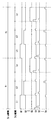
上記構成の表示部兼画素部の動作方法について、図2及び図3の回路図と、図17及び図18のタイミングチャートを用いて説明する。
【0094】
まず、EL表示部の動作方法について、図2及び図3と、図17を用いて説明する。
【0095】
なお、ここでは、ソース信号線S1〜Sxにアナログの信号を入力し、表示を行う方式(以下、アナログ方式と呼ぶ)について説明する。
【0096】
ここで、スイッチング用TFT3302及びEL駆動用TFT3303は、nチャネル型TFTであるとするが、スイッチング用TFT3302及びEL駆動用TFT3303は、それぞれnチャネル型TFTでもpチャネル型TFTでもどちらでも良い。ただし、EL素子3301の陽極が画素電極となる場合、EL駆動用TFT3303は、pチャネル型TFTであることが望ましく、逆に、EL素子3301の陰極が画素電極となる場合には、EL駆動用TFT3303は、nチャネル型TFTであることが望ましい。
【0097】
はじめ、EL表示用ゲート信号線G1に入力された信号により、EL表示用ゲート信号線G1に接続された全てのスイッチング用TFT3302が、導通状態になる。
【0098】
ある一本のEL表示用ゲート信号線が選択されている期間を、1ライン期間と呼び、特に、EL表示用ゲート信号線G1が選択されている期間を第1のライン期間L1と呼ぶ。このライン期間L1の間に、EL表示用ソース信号線S1〜Sxに順にアナログ信号が入力される。EL表示用ソース信号線に入力されたアナログ信号電圧は、コンデンサ3304及びEL駆動用TFT3303のゲート電極に印加される。EL駆動用TFT3303は、そのゲート電極に印加されたこのアナログ信号電圧に対応するソース・ドレイン間電流を、電源供給線VよりEL素子3301に流す。この電流に応じた輝度でEL素子3301は発光する。
【0099】
次に、EL表示用ゲート信号線G2が選択され、EL表示用ゲート信号線G2に接続された全てのスイッチング用TFT3302が導通状態になる。こうして、第2のライン期間L2が始まる。この後、EL表示用ソース信号線S1〜Sxに順に信号電圧が入力される。この信号電圧が、EL駆動用TFT3303のゲート電極に印加され、そのゲート電極に印加されたこのアナログ信号電圧に対応するソース・ドレイン間電流を、電源供給線VよりEL素子3301に流す。この電流に応じた輝度でEL素子3301は発光する。
【0100】
上記動作を、すべてのEL表示用ゲート信号線G1〜Gyについて繰り返し、1フレーム期間F1が終了する。その後、第2のフレーム期間F2が始まる。この動作を繰り返すことによって、画像を表示する。
【0101】
次に、センサ部の動作方法について、図2及び図3、図18を用いて説明する。
【0102】
ここで、リセット用TFT3308はnチャネル型TFTとし、バッファ用TFT3307はpチャネル型TFTとし、選択用TFT3306はnチャネル型TFTとしたが、リセット用TFT3308、バッファ用TFT3307及び選択用TFT3306はそれぞれ、nチャネル型TFTでもpチャネル型TFTでもどちらでも良い。なお、リセット用TFT3308とバッファ用TFT3307の極性は逆の方が望ましい。
【0103】
始め、リセット用ゲート信号線RG1の信号により、リセット用ゲート信号線RG1に接続された全てのリセット用TFT3308は、導通状態にある。このとき、リセット用ゲート信号線は、選択されているということにする。なお、他のリセット用ゲート信号線RG2〜RGyに接続されたすべてのりセット用TFT3308は、すべて非導通状態にある。このとき、センサ用電源線VBの電位は、リセット用TFT3308を介して、バッファ用TFT3307のゲート電極に印加される。こうして、バッファ用TFT3307のソース領域は、センサ用電源線VBの電位(基準電位)から、バッファ用TFT3307のソース領域とゲート領域の電位差を差し引いた電位に保たれている。こうしてフォトダイオード3305の電極間には、逆バイアスの電圧が印加される。
【0104】
このとき、センサ用ゲート信号線SG1の信号によって、センサ用ゲート信号線SG1に接続された全ての選択用TFT3306は、非導通状態にある。本明細書において、リセット用ゲート信号線が選択されている期間をリセット期間RSと呼ぶことにする。
【0105】
次に、リセット用ゲート信号線RG1の信号が変化し、リセット用ゲート信号線RG1に接続された全てのリセット用TFT3308が非導通状態になる。このときリセット用ゲート信号線は、非選択であるということにする。すると、フォトダイオード3305に光が照射されていると、フォトダイオード3305の電極間に電流が流れ、リセット期間中に印加された電極間の逆バイアス電圧が、低くなる。この後、センサ用ゲート信号線SG1に入力される信号によって、センサ用ゲート信号線SG1に接続された全ての選択用TFT3306が導通状態になる。
【0106】
リセット用ゲート信号線が非選択の状態になり、同じラインの画素に対応する選択用TFTが選択されるまでの期間をサンプリング期間STと呼ぶことにする。特に、リセット用ゲート信号線RG1が非選択になり、選択用ゲート信号線SG1が選択されるまでの期間を第1のサンプリング期間ST1と呼ぶことにする。
【0107】
サンプリング期間ST1において、時間の経過と共に、フォトダイオード3305の電極間の逆バイアス電圧が小さくなる。この逆バイアス電圧の低下する度合は、フォトダイオード3305の光電変換層に照射された光の強度に依存する。ここで、フォトダイオード3305のバッファ用TFT3307のゲート電極と接続されていない側の電極は、一定の電位に保たれている。よって、フォトダイオード3305のバッファ用TFT3307のゲート電極に接続されている側の電位が低下する。
【0108】
この電位の低下は、バッファ用TFT3307のゲート電極の電位を低下させる。
【0109】
ここで、バッファ用TFT3307のソース領域は、それぞれ、選択用TFT3306のドレイン・ソース間を介して定電流源2203−1〜2203−xに接続されているので、バッファ用TFT3307は、ソースフォロワとして働く。そのため、バッファ用TFT3307のゲート・ソース間電圧は、常に等しく保たれる。そのため、フォトダイオード3305の電極間の電位の変化によって、バッファ用TFT3307のゲート電極の電位が変化すると、同じ分の電位だけ、バッファ用TFT3307のソース領域の電位も変化する。サンプリング期間ST1の後、センサ用ゲート信号線SG1が選択され、このソース領域の電位の変化は、センサ用出力配線SS1〜SSxに出力される。
【0110】
その後、センサ用ゲート信号線SG1は、非選択の状態になる。
【0111】
一方、リセット用ゲート信号線RG1が非選択の状態になると、リセット用ゲート信号線RG2が選択される。リセット用ゲート信号線RG2に接続された全てのリセット用TFT3308が導通状態となり、第2ライン目のリセット期間RSが始まる。この後、リセット用ゲート信号線RG2が非選択の状態になり、第2ライン目のサンプリング期間ST2が始まる。なお、第1のサンプリング期間ST1と第2のサンプリング期間ST2は、始まる時間は異なるが、長さは同じである。
【0112】
第2のサンプリング期間ST2でも同様に、各画素のセンサ部において、入力された光の強度に応じて、フォトダイオードの電極間の逆バイアス電圧が低下する。第2のサンプリング期間ST2の後、センサ用ゲート信号線SG2の信号によって、センサ用ゲート信号線SG2に接続された全ての選択用TFT3306が導通状態となり、フォトダイオード3305の電極間の電位の変化は、バッファ用TFT3307のゲート電極に入力され、バッファ用TFT3307のソース領域の電位の変化となって、センサ用出力配線SS1〜SSxに出力される。
【0113】
その後、センサ用ゲート信号線SG2が非選択の状態となる。
【0114】
上記動作を、全てのセンサ用ゲート信号線SG1〜SGyについて繰り返し、表示部兼入力部2201の画素全部のセンサ部3312に入力された信号の情報を読み取る。
【0115】
この様に、EL表示部は、画像の表示を行う。また同時に、センサ部において、入力ペンのペン先から発した光を検出し、入力ペンのペン先が指し示した位置を特定することができる。
【0116】
【実施例】
以下に本発明の実施例について記述する。
【0117】
[実施例1]
本実施例では、実施の形態において述べた構造の情報装置を実際に作製した場合について説明する。
【0118】
本実施例では、本発明の情報装置の断面図について、図15を用いて説明する。
【0119】
601はスイッチング用TFT、602はEL駆動用TFT、603はリセット用TFT、604はバッファ用TFT、605は選択用TFTである。
【0120】
また、606はアノード電極、607は光電変換層、608はカソード電極である。アノード電極606、光電変換層607、カソード電極608とによって、フォトダイオード621が形成される。614はセンサ用配線であり、カソード電極608と外部の電源とを電気的に接続している。また、フォトダイオード621のアノード電極606とリセット用TFT603のドレイン領域とは電気的に接続されている。
【0121】
ここで、フォトダイオード621のアノード電極606は、透光性を有する材料で形成されている。
【0122】
また609は画素電極(陽極)、610はEL層、611は対向電極(陰極)である。画素電極(陽極)609と、EL層610と、対向電極(陰極)611とでEL素子622が形成される。なお612はバンクであり、隣り合う画素同士のEL層610を区切っている。
【0123】
ここで、EL素子622の画素電極609は、透光性を有する材料で形成されている。
【0124】
図15に示した構成の情報装置において、EL素子622は、基板630の方向に光を放射する。
【0125】
624は入力ペンであり、入力ペン624のペン先発光部623から発した光は、フォトダイオード621に入射する。本実施例では、入力ペン624による入力を基板630のTFTが形成されていない側から行う。なお、このペン入力を行う側は、EL素子622の光の放射側にあたり、EL素子622によって表示される画像を視認しながら情報の入力を行う。
【0126】
なお、入力ペン624のペン先発光部623から発する光は、指向性が高いものが好ましい。そのため、ペン先発光部623からレーザー光を発するような入力ペン624を用いるのが好ましい。
【0127】
また、入力ペン624のペン先発光部623から発する光として、波長の短い光、つまりエネルギーの高い光を用いるのが好ましい。例えば、紫外や近紫外の光を用いるのが好ましい。なお、本明細書中で、近紫外の光とは、紫色及び青色の可視光も含むものとする。よって、紫外発光ダイオードや近紫外発光ダイオード等を有し、ペン先発光部623からそれらの発光ダイオードの光が照射される構造の入力ペン624を用いるのが好ましい。
【0128】
この様なエネルギーの高い光を用いることで、入力ペン624によってフォトダイオード等の光電変換素子に入力され電気信号に変換された信号を、外光等のノイズの信号と比較して大きくすることができる。そのため、より信頼性の高いペン入力操作を行うことができる。
【0129】
本実施例において、スイッチング用TFT601、リセット用TFT603、選択用TFT605は全てnチャネル型TFTである。またEL駆動用TFT602、バッファ用TFT604はpチャネル型TFTである。なお、本発明はこの構成に限定されない。よってスイッチング用TFT601、EL駆動用TFT602、バッファ用TFT604、選択用TFT605、リセット用TFT603は、nチャネル型TFTとpチャネル型TFTのどちらでも良い。
【0130】
ただし本実施例のように、EL駆動用TFT602のソース領域またはドレイン領域がEL素子622の陽極609と電気的に接続されている場合、EL駆動用TFT602はpチャネル型TFTであることが望ましい。また逆に、EL駆動用TFT602のソース領域またはドレイン領域がEL素子622の陰極と電気的に接続されている場合、EL駆動用TFT602はnチャネル型TFTであることが望ましい。
【0131】
また、本実施例のように、フォトダイオード621のアノード電極606がリセット用TFT603と電気的に接続されている場合、リセット用TFT603はnチャネル型TFT、バッファ用TFT604はpチャネル型TFTであることが望ましい。逆にフォトダイオード621のカソード電極がリセット用TFT603と接続され、センサ用配線616がアノード電極と接続されている場合、リセット用TFT303はpチャネル型TFT、バッファ用TFT304はnチャネル型TFTであることが望ましい。
【0132】
[実施例2]
本実施例では、実施例1において述べた構造の情報装置において、EL素子の発光の方向が異なる例について図16を用いて説明する。
【0133】
図16に本実施例の情報装置の断面図を示す。701はスイッチング用TFT、702はEL駆動用TFT、703はリセット用TFT、704はバッファ用TFT、705は選択用TFTである。
【0134】
また、706はカソード電極、707は光電変換層、708はアノード電極である。カソード電極706、光電変換層707、アノード電極708とによって、フォトダイオード721が形成される。714はセンサ用配線であり電気的に、アノード電極708と外部の電源とを接続している。また、フォトダイオード721のカソード電極706とリセット用TFT703のドレイン領域とは電気的に接続されている。
【0135】
ここで、フォトダイオード721のアノード電極708は、透光性を有する材料で形成されている。
【0136】
また709は画素電極(陰極)、710はEL層、712は対向電極(陽極)である。画素電極(陰極)709と、EL層710と、対向電極(陽極)712とでEL素子722が形成される。なお713はバンクであり、隣り合う画素同士のEL層710を区切っている。
【0137】
ここで、EL素子722の対向電極712は、透光性を有する材料で形成されている。
【0138】
図16に示した構成の情報装置において、EL素子722は、基板730とは逆の方向に光を放射する。
【0139】
724は入力ペンであり、入力ペン724のペン先発光部723から発した光は、フォトダイオード721に入射する。本実施例では、入力ペン724による情報の入力を、基板730のTFTが形成されている側から行う。なお、このペン入力を行う側は、EL素子722の光の放射側にあたり、EL素子722によって表示される画像を視認しながら情報の入力を行う。
【0140】
なお、入力ペン724のペン先発光部723から発する光は、指向性が高いものが好ましい。そのため、ペン先発光部723からレーザー光を発するような入力ペン724を用いるのが好ましい。
【0141】
また、入力ペン624のペン先発光部623から発する光として、波長の短い光、つまりエネルギーの高い光を用いるのが好ましい。例えば、紫外や近紫外の光を用いるのが好ましい。なお、本明細書中で、近紫外の光とは、紫色及び青色の可視光も含むものとする。よって、紫外発光ダイオードや近紫外発光ダイオード等を有し、ペン先発光部623からそれらの発光ダイオードの光が照射される構造の入力ペン624を用いるのが好ましい。
【0142】
この様なエネルギーの高い光を用いることで、入力ペン624によってフォトダイオード等の光電変換素子に入力され電気信号に変換された信号を、外光等のノイズの信号と比較して大きくすることができる。そのため、より信頼性の高いペン入力操作を行うことができる。
【0143】
本実施例において、スイッチング用TFT701、EL駆動用TFT702、バッファ用TFT704、選択用TFT705は全てnチャネル型TFTである。またリセット用TFT703はpチャネル型TFTである。なお本発明はこの構成に限定されない。よってスイッチング用TFT701、EL駆動用TFT702、バッファ用TFT704、選択用TFT705、リセット用TFT703は、nチャネル型TFTとpチャネル型TFTのどちらでも良い。
【0144】
ただし本実施例のように、EL駆動用TFT702のソース領域またはドレイン領域がEL素子722の陰極709と電気的に接続されている場合、EL駆動用TFT702はnチャネル型TFTであることが望ましい。また逆に、EL駆動用TFT702のソース領域またはドレイン領域がEL素子722の陽極712と電気的に接続されている場合、EL駆動用TFT702はpチャネル型TFTであることが望ましい。
【0145】
また、本実施例のように、フォトダイオード721のカソード電極706がリセット用TFT703と電気的に接続されている場合、リセット用TFT703はpチャネル型TFT、バッファ用TFT704はnチャネル型TFTであることが望ましい。逆にフォトダイオード721のアノード電極がリセット用TFT703と接続され、センサ用配線714がカソード電極と接続されている場合、リセット用TFT703はnチャネル型TFT、バッファ用TFT704はpチャネル型TFTであることが望ましい。
【0146】
[実施例3]
本実施例では、実施の形態で示したのとは異なる、表示部兼入力部の動作方法について説明する。なお、画素部兼入力部の構成は、実施の形態で示したものと同じであり図2及び図3を参照し説明は省略する。また、本実施例のセンサ部の動作方法も実施の形態で示したものと同じであり、図18を参照する。本実施例のEL表示部の動作方法を示すタイミングチャートを図5に示す。
【0147】
まず、1フレーム期間(F)をN個のサブフレーム期間(SF1〜SFN)に分割する。階調数が多くなるにつれて1フレーム期間におけるサブフレーム期間の数も増える。なおエリアセンサのセンサ部が画像を表示する場合、1フレーム期間(F)とは、表示部兼入力部の全ての画素のEL表示部が1つの画像を表示する期間を指す。
【0148】
本実施例の場合、フレーム期間は1秒間に60以上設けることが好ましい。1秒間に表示される画像の数を60以上にすることで、視覚的にフリッカ等の画像のちらつきを抑えることが可能になる。
【0149】
サブフレーム期間はアドレス期間(Ta)とサステイン期間(Ts)とに分けられる。アドレス期間とは、1サブフレーム期間中、全ての画素にデジタルビデオ信号を入力する期間である。なおデジタルビデオ信号とは、画像情報を有するデジタルの信号である。サステイン期間(点灯期間とも呼ぶ)とは、アドレス期間において画素に入力されたデジタルビデオ信号によって、EL素子を発光又は非発光の状態にし、表示を行う期間を示している。なおデジタルビデオ信号とは、画像情報を有するデジタルの信号を意味する。
【0150】
SF1〜SFNが有するアドレス期間(Ta)をそれぞれTa1〜TaNとする。SF1〜SFNが有するサステイン期間(Ts)をそれぞれTs1〜TsNとする。
【0151】
電源供給線(V1〜Vx)の電位は所定の電位(電源電位)に保たれている。
【0152】
まずアドレス期間Taにおいて、EL素子3301対向電極の電位は、電源電位と同じ高さに保たれている。
【0153】
次にEL表示用ゲート信号線G1に入力される信号によって、EL表示用ゲート信号線G1に接続されている全てのスイッチング用TFT3302が導通状態になる。次に、EL表示用ソース信号線(S1〜Sx)にデジタルビデオ信号が入力される。デジタルビデオ信号は「0」または「1」の情報を有しており、「0」と「1」のデジタルビデオ信号は、一方がHi、一方がLoの電圧を有する信号である。
【0154】
そしてEL表示用ソース信号線(S1〜Sx)に入力されたデジタルビデオ信号は、導通状態のスイッチング用TFT3302を介して、EL駆動用TFT3303のゲート電極に入力される。
【0155】
次にEL表示用ゲート信号線G1に接続されている全てのスイッチング用TFT3302が非導通状態になり、EL表示用ゲート信号線G2に入力されるゲート信号によって、EL表示用ゲート信号線G2に接続されている全てのスイッチング用TFT3302が導通状態になる。次に、EL表示用ソース信号線(S1〜Sx)にデジタルビデオ信号が入力される。EL表示用ソース信号線(S1〜Sx)に入力されたデジタルビデオ信号は、導通状態のスイッチング用TFT3302を介して、EL駆動用TFT3303のゲート電極に入力される。
【0156】
上述した動作をEL表示用ゲート信号線Gyまで繰り返し、全ての画素のEL駆動用TFT3303のゲート電極にデジタルビデオ信号が入力され、アドレス期間が終了する。
【0157】
アドレス期間Taが終了すると同時にサステイン期間Tsとなる。サステイン期間において、全てのスイッチング用TFT3302はオフの状態になる。サステイン期間において、全てのEL素子3301の対向電極の電位は、電源電位が画素電極に与えられたときにEL素子3301が発光する程度に、電源電位との間に電位差を有する高さになる。
【0158】
本実施例では、デジタルビデオ信号が「0」の情報を有していた場合、EL駆動用TFT3303は非導通状態になる。よってEL素子3301の画素電極は対向電極の電位に保たれたままである。その結果、「0」の情報を有するデジタルビデオ信号が入力された画素において、EL素子3301は発光しない。
【0159】
逆にデジタルビデオ信号が「1」の情報を有していた場合、EL駆動用TFT3303は導通状態になる。よって電源電位がEL素子3301の画素電極に与えられる。その結果、「1」の情報を有するデジタルビデオ信号が入力された画素が有するEL素子3301は発光する。
【0160】
このように、画素に入力されるデジタルビデオ信号の有する情報によって、EL素子が発光または非発光の状態になり、画素は表示を行う。
【0161】
サステイン期間が終了すると同時に、1つのサブフレーム期間が終了する。そして次のサブフレーム期間が出現し、再びアドレス期間に入り、全画素にデジタルビデオ信号を入力したら、再びサステイン期間に入る。なお、サブフレーム期間SF1〜SFNの出現する順序は任意である。
【0162】
以下、残りのサブフレーム期間においても同様の動作を繰り返し、表示を行う。N個のサブフレーム期間が全て終了したら、1つの画像が表示され、1フレーム期間が終了する。1フレーム期間が終了すると次のフレーム期間のサブフレーム期間が出現し、上述した動作を繰り返す。
【0163】
本発明において、N個のサブフレーム期間がそれぞれ有するアドレス期間(Ta1〜TaN)の長さは全て同じである。またN個のサステイン期間Ts1、…、TsNの長さの比は、Ts1:Ts2:Ts3:…:Ts(N−1):TsN=20:2-1:2-2:…:2-(N-2):2-(N-1)で表される。
【0164】
各画素の階調は、1フレーム期間においてどのサブフレーム期間を発光させるかによって決まる。例えば、N=8のとき、全部のサステイン期間で発光した場合の画素の輝度を100%とすると、Ts1とTs2において画素が発光した場合には75%の輝度が表現でき、Ts3とTs5とTs8を選択した場合には16%の輝度が表現できる。
【0165】
上記のように画素のEL素子を発光させて、画像表示を行う手法をデジタル方式とよぶことにする。
【0166】
次に、センサ部の動作方法について、図2及び図3、図18を用いて説明する。
【0167】
ここで、リセット用TFT3308はnチャネル型TFTとし、バッファ用TFT3307はpチャネル型TFTとし、選択用TFT3306はnチャネル型TFTとしたが、リセット用TFT3308、バッファ用TFT3307及び選択用TFT3306はそれぞれ、nチャネル型TFTでもpチャネル型TFTでもどちらでも良い。なお、リセット用TFT3308とバッファ用TFT3307の極性は逆の方が望ましい。
【0168】
始め、リセット用ゲート信号線RG1の信号により、リセット用ゲート信号線RG1に接続された全てのリセット用TFT3308は、導通状態にある。このとき、リセット用ゲート信号線は、選択されているということにする。なお、他のリセット用ゲート信号線RG2〜RGyに接続されたすべてのりセット用TFT3308は、すべて非導通状態にある。このとき、センサ用電源線VBの電位は、リセット用TFT3308を介して、バッファ用TFT3307のゲート電極に印加される。こうして、バッファ用TFT3307のソース領域は、センサ用電源線VBの電位(基準電位)から、バッファ用TFT3307のソース領域とゲート領域の電位差を差し引いた電位に保たれている。こうしてフォトダイオード3305の電極間には、逆バイアスの電圧が印加される。
【0169】
このとき、センサ用ゲート信号線SG1の信号によって、センサ用ゲート信号線SG1に接続された全ての選択用TFT3306は、非導通状態にある。本明細書において、リセット用ゲート信号線が選択されている期間をリセット期間RSと呼ぶことにする。
【0170】
次に、リセット用ゲート信号線RG1の信号が変化し、リセット用ゲート信号線RG1に接続された全てのリセット用TFT3308が非導通状態になる。このときリセット用ゲート信号線は、非選択であるということにする。すると、フォトダイオード3305に光が照射されていると、フォトダイオード3305の電極間に電流が流れ、リセット期間中に印加された電極間の逆バイアス電圧が、低くなる。この後、センサ用ゲート信号線SG1に入力される信号によって、センサ用ゲート信号線SG1に接続された全ての選択用TFT3306が導通状態になる。
【0171】
リセット用ゲート信号線が非選択の状態になり、同じラインの画素に対応する選択用TFTが選択されるまでの期間をサンプリング期間STと呼ぶことにする。特に、リセット用ゲート信号線RG1が非選択になり、選択用ゲート信号線SG1が選択されるまでの期間を第1のサンプリング期間ST1と呼ぶことにする。
【0172】
サンプリング期間ST1において、時間の経過と共に、フォトダイオード3305の電極間の逆バイアス電圧が小さくなる。この逆バイアス電圧の低下する度合は、フォトダイオード3305の光電変換層に照射された光の強度に依存する。ここで、フォトダイオード3305のバッファ用TFT3307のゲート電極と接続されていない側の電極は、一定の電位に保たれている。よって、フォトダイオード3305のバッファ用TFT3307のゲート電極に接続されている側の電位が低下する。
【0173】
この電位の低下は、バッファ用TFT3307のゲート電極の電位を低下させる。
【0174】
ここで、バッファ用TFT3307のソース領域は、それぞれ、選択用TFT3306のドレイン・ソース間を介して定電流源2203−1〜2203−xに接続されているので、バッファ用TFT3307は、ソースフォロワとして働く。そのため、バッファ用TFT3307のゲート・ソース間電圧は、常に等しく保たれる。そのため、フォトダイオード3305の電極間の電位の変化によって、バッファ用TFT3307のゲート電極の電位が変化すると、同じ分の電位だけ、バッファ用TFT3307のソース領域の電位も変化する。サンプリング期間ST1の後、センサ用ゲート信号線SG1が選択され、このソース領域の電位の変化は、センサ用出力配線SS1〜SSxに出力される。
【0175】
その後、センサ用ゲート信号線SG1は、非選択の状態になる。
【0176】
一方、リセット用ゲート信号線RG1が非選択の状態になると、リセット用ゲート信号線RG2が選択される。リセット用ゲート信号線RG2に接続された全てのリセット用TFT3308が導通状態となり、第2ライン目のリセット期間RSが始まる。この後、リセット用ゲート信号線RG2が非選択の状態になり、第2ライン目のサンプリング期間ST2が始まる。なお、第1のサンプリング期間ST1と第2のサンプリング期間ST2は、始まる時間は異なるが、長さは同じである。
【0177】
第2のサンプリング期間ST2でも同様に、各画素のセンサ部において、入力された光の強度に応じて、フォトダイオードの電極間の逆バイアス電圧が低下する。第2のサンプリング期間ST2の後、センサ用ゲート信号線SG2の信号によって、センサ用ゲート信号線SG2に接続された全ての選択用TFT3306が導通状態となり、フォトダイオード3305の電極間の電位の変化は、バッファ用TFT3307のゲート電極に入力され、バッファ用TFT3307のソース領域の電位の変化となって、センサ用出力配線SS1〜SSxに出力される。
【0178】
その後、センサ用ゲート信号線SG2が非選択の状態となる。
【0179】
上記動作を、全てのセンサ用ゲート信号線SG1〜SGyについて繰り返し、表示部兼入力部2201の画素全部のセンサ部3312に入力された信号の情報を読み取る。
【0180】
こうして、入力ペンのペン先の位置を特定することができる。
【0181】
なお本実施例は、実施例1〜実施例2と自由に組み合わせることが可能である。
【0182】
[実施例4]
本発明の情報装置において、入力ペンによって情報の入力を行うだけではなく、イメージセンサとしても用いることができる。
【0183】
図20は、本発明の情報装置をイメージセンサとして用いた場合の模式図である。
【0184】
情報装置の表示部兼入力部の回路構成は、実施の形態と同様であるので、説明はここでは省略する。また、図20の模式図において、図15と同様の部分は、同じ符号を用いて示し説明は省略する。
【0185】
また、表示部兼入力部を駆動する方法は、実施の形態や、実施例3で示した手法と同様の手法を用いることができるので、説明は、ここでは省略する。
【0186】
本発明の情報装置の表示部兼入力部の、ペン入力を行う側に、読みとりたい物体(読みとり対象物体:625)を近づける。ここで、実施の形態や、実施例3等で示したのと同様の手法で、各画素のEL素子622を発光させる。このEL素子622の発光を用いて、読みとり対象物体625に光を照射する。つまり、各画素のEL素子622は、読みとり対象物体625の情報を読みとるための照明装置として用いられる。
【0187】
そのため、本発明の情報装置をイメージセンサとして用いる際は、各画素のEL素子の発光輝度は、全て同じにするのが望ましい。
【0188】
つまり、実施の形態において示したような、アナログ方式によって各画素のEL素子を駆動する場合は、全ての画素に、EL用ソース信号線より入力されるアナログの信号を、等しくする。
【0189】
一方、実施例3に示したような、デジタル方式によって、各画素のEL素子を駆動させる場合は、全ての画素が、1フレーム期間内に同じ長さの時間だけ発光するようにする。なお、できる限り連続的に光を照射するために、全ての画素のEL素子が、1フレーム期間内の全てのサスティン期間において発光するように設定するのが望ましい。
【0190】
こうして、読みとり対象物体625に照射された光は、読みとり対象物体625表面で反射され、各画素のセンサ部のフォトダイオード621に入力される。この入力された光が電気信号に変換され、センサ用駆動回路(センサ用ソース信号線駆動回路、センサ用ゲート信号線駆動回路)によって読み出され、読みとり対象物体625の表面の情報が、画像として得られる。
【0191】
ここで、本実施例では、実施例1に示した構成の情報装置を用いて説明を行ったが、実施例2において図16で示した構成の情報装置を用い、表示部兼画素部の形成された基板の、TFTが形成された側から、読み取り対象物体を近づけて、読み取り対象物体表面の情報を読み取ることもできる。
【0192】
なお、本実施例は、実施例1〜実施例3と自由に組み合わせて実施することが可能である。
【0193】
[実施例5]
本発明の情報装置の表示部兼入力部の作製方法について、図10〜図14を用いて説明する。
【0194】
まず、図10(A)において、本実施例ではコーニング社の#7059ガラスや#1737ガラスなどに代表されるバリウムホウケイ酸ガラス、またはアルミノホウケイ酸ガラスなどのガラスからなる基板200を用いる。なお、基板200としては、透光性を有する基板であれば限定されず、石英基板を用いてもよく、また、ガラス基板、セラミック基板等を用いてもよい。また、本実施例の処理温度に耐えうる耐熱性を有するプラスチック基板を用いてもよい。
【0195】
また基板200としては、ステンレス基板を用いてもよい。しかし、ステンレス基板は、透明ではないため、EL素子が発する光が基板200とは反対側に放射される場合のみ有効である。
【0196】
次に基板200を覆うように、基板200上に酸化珪素からなる絶縁膜を形成する。絶縁膜は、酸化珪素膜、窒化珪素膜または酸化窒化珪素膜を用いることができる。例えば、プラズマCVD法でSiH4、NH3、N2Oから作製される酸化窒化珪素膜を250〜800nm(好ましくは300〜500nm)、同様にSiH4、N2Oから作製される酸化窒化水素化珪素膜を250〜800nm(好ましくは300〜500nm)の厚さに積層して形成しても良い。ここでは酸化珪素からなる絶縁膜を単層構造とし、0.5〜1.5μmの厚さに形成した。なお絶縁膜の材料は酸化珪素に限定されない。
【0197】
次にCMP法で該絶縁膜を研磨することで平坦化絶縁膜201が形成される。CMP法は公知の方法で行うことが可能である。酸化膜の研磨では、一般的に100〜1000nmφの研磨剤を、PH調整剤等の試薬を含む水溶液に分散させた固液分散系のスラリーが用いられる。本実施例では、水酸化カリウムが添加された水溶液に、塩化珪素ガスを熱分解して得られるフュームドシリカ粒子を20wt%分散したシリカスラリー(PH=10〜11)を用いる。
【0198】
平坦化絶縁膜201形成後、平坦化絶縁膜201上に半導体層202〜206を形成する。半導体層202〜206は、非晶質構造を有する半導体膜を公知の手段(スパッタ法、LPCVD法、またはプラズマCVD法等)により成膜した後、公知の結晶化処理(レーザー結晶化法、熱結晶化法、またはニッケルなどの触媒を用いた熱結晶化法等)を行って得られた結晶質半導体膜を所望の形状にパターニングして形成する。この半導体層202〜206の厚さは25〜80nm(好ましくは30〜60nm)の厚さで形成する。結晶質半導体膜の材料に限定はないが、好ましくは珪素またはシリコンゲルマニウム(SiXGe1-X(X=0.0001〜0.02))合金などで形成すると良い。本実施例では、プラズマCVD法を用い、55nmの非晶質珪素膜を成膜した後、ニッケルを含む溶液を非晶質珪素膜上に保持させた。この非晶質珪素膜に脱水素化(500℃、1時間)を行った後、熱結晶化(550℃、4時間)を行い、さらに結晶化を改善するためのレーザーアニ―ル処理を行って結晶質珪素膜を形成した。そして、この結晶質珪素膜をフォトリソグラフィ法を用いたパターニング処理によって、半導体層202〜206を形成した。
【0199】
また、半導体層202〜206を形成した後、TFTのしきい値を制御するために微量な不純物元素(ボロンまたはリン)のドーピングを行ってもよい。
【0200】
また、レーザー結晶化法で結晶質半導体膜を作製する場合には、パルス発振型または連続発光型のエキシマレーザーやYAGレーザー、YVO4レーザーを用いることができる。これらのレーザーを用いる場合には、レーザー発振器から放射されたレーザー光を光学系で線状に集光し半導体膜に照射する方法を用いると良い。結晶化の条件は実施者が適宣選択するものであるが、エキシマレーザーを用いる場合はパルス発振周波数300Hzとし、レーザーエネルギー密度を100〜400mJ/cm2(代表的には200〜300mJ/cm2)とする。また、YAGレーザーを用いる場合にはその第2高調波を用いパルス発振周波数30〜300kHzとし、レーザーエネルギー密度を300〜600mJ/cm2(代表的には350〜500mJ/cm2)とすると良い。そして幅100〜1000μm、例えば400μmで線状に集光したレーザー光を基板全面に渡って照射し、この時の線状レーザー光の重ね合わせ率(オーバーラップ率)を50〜98%として行えばよい。
【0201】
次いで、半導体層202〜206を覆うゲート絶縁膜209を形成する。ゲート絶縁膜209はプラズマCVD法またはスパッタ法を用い、厚さを40〜150nmとして珪素を含む絶縁膜で形成する。本実施例では、プラズマCVD法により110nmの厚さで酸化窒化珪素膜(組成比Si=32%、O=59%、N=7%、H=2%)で形成した。勿論、ゲート絶縁膜は酸化窒化珪素膜に限定されるものでなく、他の珪素を含む絶縁膜を単層または積層構造として用いても良い。
【0202】
また、酸化珪素膜を用いる場合には、プラズマCVD法でTEOS(Tetraethyl Orthosilicate)とO2とを混合し、反応圧力40Pa、基板温度300〜400℃とし、高周波(13.56MHz)電力密度0.5〜0.8W/cm2で放電させて形成することができる。このようにして作製される酸化珪素膜は、その後400〜500℃の熱アニールによりゲート絶縁膜として良好な特性を得ることができる。
【0203】
次いで、図10(A)に示すように、ゲート絶縁膜209上に膜厚20〜100nmの第1の導電膜210aと、膜厚100〜400nmの第2の導電膜210bとを積層形成する。本実施例では、膜厚30nmのTaN膜からなる第1の導電膜210aと、膜厚370nmのW膜からなる第2の導電膜210bを積層形成した。TaN膜はスパッタ法で形成し、Taのターゲットを用い、窒素を含む雰囲気内でスパッタした。また、W膜は、Wのターゲットを用いたスパッタ法で形成した。その他に6フッ化タングステン(WF6)を用いる熱CVD法で形成することもできる。いずれにしてもゲート電極として使用するためには低抵抗化を図る必要があり、W膜の抵抗率は20μΩcm以下にすることが望ましい。W膜は結晶粒を大きくすることで低抵抗率化を図ることができるが、W膜中に酸素などの不純物元素が多い場合には結晶化が阻害され高抵抗化する。従って、本実施例では、高純度のW(純度99.9999%)のターゲットを用いたスパッタ法で、さらに成膜時に気相中からの不純物の混入がないように十分配慮してW膜を形成することにより、抵抗率9〜20μΩcmを実現することができた。
【0204】
なお、本実施例では、第1の導電膜210aをTaN、第2の導電膜210bをWとしたが、特に限定されず、いずれもTa、W、Ti、Mo、Al、Cu、Cr、Ndから選ばれた元素、または前記元素を主成分とする合金材料若しくは化合物材料で形成してもよい。また、リン等の不純物元素をドーピングした多結晶珪素膜に代表される半導体膜を用いてもよい。また、AgPdCu合金を用いてもよい。また、第1の導電膜をタンタル(Ta)膜で形成し、第2の導電膜をW膜とする組み合わせ、第1の導電膜を窒化チタン(TiN)膜で形成し、第2の導電膜をW膜とする組み合わせ、第1の導電膜を窒化タンタル(TaN)膜で形成し、第2の導電膜をAl膜とする組み合わせ、第1の導電膜を窒化タンタル(TaN)膜で形成し、第2の導電膜をCu膜とする組み合わせとしてもよい。
【0205】
次に、フォトリソグラフィ法を用いてレジストからなるマスク211を形成し、電極及び配線を形成するための第1のエッチング処理を行う(図10(B))。第1のエッチング処理では第1及び第2のエッチング条件で行う。本実施例では第1のエッチング条件として、ICP(Inductively Coupled Plasma:誘導結合型プラズマ)エッチング法を用い、エッチング用ガスにCF4とCl2とO2とを用い、それぞれのガス流量比を25/25/10(sccm)とし、1Paの圧力でコイル型の電極に500WのRF(13.56MHz)電力を投入してプラズマを生成してエッチングを行った。ここでは、松下電器産業(株)製のICPを用いたドライエッチング装置(Model E645−□ICP)を用いた。基板側(試料ステージ)にも150WのRF(13.56MHz)電力を投入し、実質的に負の自己バイアス電圧を印加する。この第1のエッチング条件によりW膜をエッチングして第1の導電層の端部をテーパー形状とする。第1のエッチング条件でのWに対するエッチング速度は200.39nm/min、TaNに対するエッチング速度は80.32nm/minであり、TaNに対するWの選択比は約2.5である。また、この第1のエッチング条件によって、Wのテーパー角は、約26°となる。
【0206】
上記第1のエッチング処理では、レジストからなるマスク211の形状を適したものとすることにより、基板側に印加するバイアス電圧の効果により第1の導電層及び第2の導電層の端部がテーパー形状となる。このテーパー部の角度は15〜45°とすればよい。こうして、第1のエッチング処理により第1の導電層と第2の導電層から成る第1の形状の導電層212〜216(第1の導電層212a〜216aと第2の導電層212b〜216b)を形成する。217はゲート絶縁膜であり、第1の形状の導電層212〜216で覆われない領域は20〜50nm程度エッチングされ薄くなった領域が形成される。
【0207】
次いで、レジストからなるマスクを除去せずに第2のエッチング処理を行う(図10(C))。ここでは、エッチング用ガスにCF4とCl2とO2とを用い、それぞれのガス流量比を25/25/10(sccm)とし、1Paの圧力でコイル型の電極に500WのRF(13.56MHz)電力を投入してプラズマを生成してエッチングを行った。基板側(試料ステージ)にも20WのRF(13.56MHz)電力を投入し、実質的に負の自己バイアス電圧を印加する。第2のエッチング処理でのWに対するエッチング速度は124.62nm/min、TaNに対するエッチング速度は20.67nm/minであり、TaNに対するWの選択比は6.05である。従って、W膜が選択的にエッチングされる。この第2のエッチングによりWのテーパー角は70°となった。この第2のエッチング処理により第2の導電層218b〜222bを形成する。一方、第1の導電層218a〜222aは、ほとんどエッチングされず、第1の導電層218a〜222aが形成される。223はゲート絶縁膜であり、第2の形状の導電層218〜222で覆われない領域は20〜50nm程度エッチングされ薄くなった領域が形成される。
【0208】
第1の導電層218aと第2の導電層218bとで形成された電極は、後の工程で形成されるnチャネル型のバッファ用TFTとなり、第1の導電層219aと第2の導電層219bとで形成された電極は、後の工程で形成されるnチャネル型の選択用TFTとなる。同様に、第1の導電層220aと第2の導電層220bとで形成された電極は、後の工程で形成されるpチャネル型のリセット用TFTとなり、第1の導電層221aと第2の導電層221bとで形成された電極は、後の工程で形成されるnチャネル型のスイッチング用TFTとなり、第1の導電層222aと第2の導電層222bとで形成された電極は、後の工程で形成されるpチャネル型のEL駆動用TFTとなる。
【0209】
次いで、第1のドーピング処理を行って図11(A)の状態を得る。ドーピングは第2の導電層218b〜222bを不純物元素に対するマスクとして用い、第1の導電層218a〜222aのテーパー部下方の半導体層に不純物元素が添加されるようにドーピングする。本実施例では、不純物元素としてP(リン)を用い、ドーズ量3.5×10¹²atoms/cm3、加速電圧90keVにてプラズマドーピングを行った。こうして第1の導電層と重ならない低濃度不純物領域224a〜228aと、第1の導電層と重なる低濃度不純物領域224b〜228bを自己整合的に形成する。低濃度不純物領域224b〜228bへ添加されたリン(P)の濃度は、1×1017〜1×1018atoms/cm3であり、且つ、第1の導電層218a〜222aのテーパー部の膜厚に従って緩やかな濃度勾配を有している。なお、第1の導電層218a〜222aのテーパー部と重なる半導体層において、第1の導電層218a〜222aのテーパー部の端部から内側に向かって、若干不純物濃度が低くなっているものの、ほぼ同程度の濃度である。
【0210】
そして、レジストからなるマスク231を形成し、第2のドーピング処理を行い、半導体層にn型を付与する不純物元素を添加する(図11(B))。ドーピング処理はイオンドープ法、若しくはイオン注入法で行えば良い。イオンドープ法の条件はドーズ量を1×10¹³〜5×10¹⁵atoms/cm3とし、加速電圧を60〜100keVとして行う。本実施例ではドーズ量を1.5×1015atoms/cm3とし、加速電圧を80keVとして行った。n型を付与する不純物元素として15族に属する元素、典型的にはリン(P)または砒素(As)を用いるが、ここではリン(P)を用いた。この場合、導電層218〜222がn型を付与する不純物元素に対するマスクとなり、自己整合的に高濃度不純物領域232a〜236a、第1の導電層と重ならない低濃度不純物領域232b〜236b、第1の導電層と重なる低濃度不純物領域232c〜236cが形成される。高濃度不純物領域232a〜236aには1×1020〜1×1021atoms/cm3の濃度範囲でn型を付与する不純物元素を添加する。
【0211】
なおpチャネル型の半導体膜が形成される半導体膜には、図11(B)に示した第2のドーピング処理によりn型の不純物をドーピングする必要はないため、マスク231を半導体層204、206上に完全に覆うように形成し、n型の不純物がドーピングされないようにしても良い。逆にマスク231を半導体層204、206上に設けず、第3のドーピング処理において半導体層の極性をp型に反転させても良い。
【0212】
次いで、レジストからなるマスク231を除去した後、新たにレジストからなるマスク239を形成して第3のドーピング処理を行う。この第3のドーピング処理により、pチャネル型TFTの活性層となる半導体層に前記一導電型(n型)とは逆の導電型(p型)を付与する不純物元素が添加された不純物領域240a〜240c、241a〜241cを形成する(図11(C))。第1の導電層220b、222bを不純物元素に対するマスクとして用い、p型を付与する不純物元素を添加して自己整合的に不純物領域を形成する。本実施例では、不純物領域240a〜240c、241a〜241cはジボラン(B2H6)を用いたイオンドープ法で形成する。なお、この第3のドーピング処理の際には、nチャネル型TFTを形成する半導体層はレジストからなるマスク239で覆われている。第1のドーピング処理及び第2のドーピング処理によって、不純物領域240a、240b、240cにはそれぞれ異なる濃度でリンが添加されているが、そのいずれの領域においてもp型を付与する不純物元素の濃度が2×10²⁰〜2×10²¹atoms/cm3となるようにドーピング処理することにより、pチャネル型TFTのソース領域およびドレイン領域として機能するために何ら問題は生じない。
【0213】
次いで、それぞれの半導体層に添加された不純物元素を活性化処理する工程を行う。この活性化工程は、ファーネスアニール炉を用いる熱アニール炉で行う。熱アニール法としては、酸素濃度が1PPm以下、好ましくは0.1PPm以下の窒素雰囲気中で400〜700℃、代表的には500〜550℃で行えばよく、本実施例では550℃、4時間の熱処理で活性化処理を行った。なお、熱アニール法の他に、レーザーアニール法、またはラピッドサーマルアニール法(RTA法)などを適用することができる。
【0214】
また、第1の層間絶縁膜を形成した後に活性化処理を行ってもよい。ただし、配線に用いた配線材料が熱に弱い場合には、本実施例のように配線等を保護するため層間絶縁膜(シリコンを主成分とする絶縁膜、例えば窒化珪素膜)を形成した後で活性化処理を行うことが好ましい。
【0215】
さらに、3〜100%の水素を含む雰囲気中で、300〜550℃で1〜12時間の熱処理を行い、半導体層を水素化する工程を行う。本実施例では、水素を約3%含む窒素雰囲気中で410℃、1時間の熱処理を行った。この工程は熱的に励起された水素により半導体膜の不対結合手を水素終端する工程である。水素化の他の手段として、プラズマ水素化(プラズマにより励起された水素を用いる。)を用いることもできる。
【0216】
また、パッシベーション膜を形成した後に水素化する工程を行ってもよい。
【0217】
以上までの工程でそれぞれの半導体層に不純物領域が形成される。
【0218】
次いで、レジストからなるマスク239を除去し、第3のエッチング処理を行う。本実施例では導電層218〜222をマスクとして用いて、ゲート絶縁膜をエッチング処理する。
【0219】
第3のエッチング処理により、ゲート絶縁膜243c〜247cが、第2の導電層243b〜247bの下方に形成される(図12(A))。
【0220】
次いで、基板200を覆うように、パッシベーション膜291を形成する(図12(B))。パッシベーション膜291は、酸化珪素膜、窒化珪素膜または酸化窒化珪素膜を用いることができる。例えば、プラズマCVD法でSiH4、NH3、N2Oから作製される酸化窒化珪素膜を250〜800nm(好ましくは300〜500nm)、同様にSiH4、N2Oから作製される酸化窒化水素化珪素膜を250〜800nm(好ましくは300〜500nm)の厚さに積層して形成してもよい。本実施例では酸化窒素からなるパッシベーション膜291を、単層構造とし、0.5〜1.5μmの厚さで形成した。
【0221】
次いで、第1層間絶縁膜249を形成する。プラズマCVD法またはスパッタ法を用い、厚さを100〜200nmとして珪素を含む絶縁膜で形成する。本実施例では、プラズマCVD法により膜厚150nmの酸化窒化珪素膜を形成した。勿論、第1層間絶縁膜249は酸化窒化珪素膜に限定されるものでなく、他の珪素を含む絶縁膜を単層または積層構造として用いても良い。次いで、各不純物領域232a、233a、235a、238、240a、241a、242に達するコンタクトホールを形成するためのパターニングを行う。
【0222】
次いで、ソース配線251〜255、ドレイン配線257〜261を形成する(図12(C))。なお、本実施例では、この配線の材料としては、AlまたはAgを主成分とする膜、またはそれらの積層膜等の反射性の優れた材料を用いることが望ましい。
【0223】
次に、図13(A)に示すように50〜500nm(代表的には200〜300nm)の厚さで第2パッシベーション膜268を形成する。本実施例では第2パッシベーション膜268として300nm厚の窒化酸化珪素膜を用いる。これは窒化珪素膜で代用しても良い。なお、窒化酸化珪素膜の形成に先立ってH2、NH3等水素を含むガスを用いてプラズマ処理を行うことは有効である。
【0224】
次に、有機樹脂からなる第2層間絶縁膜269を形成する。有機樹脂としてはポリイミド、ポリアミド、アクリル、BCB(ベンゾシクロブテン)等を使用することができる。特に、第2層間絶縁膜269は平坦化の意味合いが強いので、平坦性に優れたアクリルが好ましい。本実施例ではTFTによって形成される段差を十分に平坦化しうる膜厚でアクリル膜を形成する。好ましくは1〜5μm(さらに好ましくは2〜4μm)とすれば良い。
【0225】
次に、第2層間絶縁膜269及び第2パッシベーション膜268にドレイン配線259に達するコンタクトホールを形成し、ドレイン配線259に接するようにフォトダイオードのカソード電極270を形成する。本実施例では、カソード電極270としてスパッタ法によって形成したアルミニウム膜を用いたが、その他の金属、例えばチタン、タンタル、タングステン、銅を用いることができる。また、チタン、アルミニウム、チタンでなる積層膜を用いてもよい。
【0226】
次に、水素を含有する非晶質珪素膜を基板全面に成膜した後にパターニングし、光電変換層271を形成する。次に、基板全面に透明導電膜を形成する。本実施例では透明導電膜として厚さ200nmのITOをスパッタ法で成膜する。透明導電膜をパターニングし、アノード電極272を形成する。(図13(B))
【0227】
次に、図14(A)に示すように第3層間絶縁膜273を形成する。第3層間絶縁膜273として、ポリイミド、ポリアミド、ポリイミドアミド、アクリル等の樹脂を用いることで、平坦な表面を得ることができる。本実施例では、第3層間絶縁膜273として厚さ0.7μmのポリイミド膜を基板全面に形成した。
【0228】
次に、第3層間絶縁膜273、第2層間絶縁膜269及び第2パッシベーション膜268にドレイン配線261に達するコンタクトホールを形成し、画素電極275を形成する。また第3層間絶縁膜273に、アノード電極272に達するコンタクトホールを形成し、センサ用配線274を形成する。本実施例ではアルミニウム合金膜(1wt%のチタンを含有したアルミニウム膜)を300nmの厚さに形成し、パターニングを行ってセンサ用配線274及び画素電極275を同時に形成する。
【0229】
次に、図14(B)に示すように、樹脂材料でなるバンク276を形成する。バンク276は1〜2μm厚のアクリル膜またはポリイミド膜をパターニングして形成すれば良い。バンク276はソース配線254上に沿って形成しても良いし、ゲート配線(図示せず)上に沿って形成しても良い。なおバンク276を形成している樹脂材料に顔料等を混ぜ、バンク276を遮蔽膜として用いても良い。
【0230】
次に、発光層277を形成する。具体的には、発光層277となる有機EL材料をクロロフォルム、ジクロロメタン、キシレン、トルエン、テトラヒドロフラン等の溶媒に溶かして塗布し、その後、熱処理を行うことにより溶媒を揮発させる。こうして有機EL材料でなる被膜(発光層)が形成される。
【0231】
なお、本実施例では一画素しか図示されていないが、カラー表示を行う情報装置を作製する場合は、このとき同時に赤色に発光する発光層、緑色に発光する発光層及び青色に発光する発光層が形成される。本実施例では、赤色に発光する発光層としてシアノポリフェニレンビニレン、緑色に発光する発光層としてポリフェニレンビニレン、青色に発光する発光層としてポリアルキルフェニレンを各々50nmの厚さに形成する。また、溶媒としては1,2−ジクロロメタンを用い、80〜150℃のホットプレートで1〜5分の熱処理を行って揮発させる。
【0232】
本実施例ではEL層を発光層でなる1層構造とするが、その他に正孔注入層、正孔輸送層、電子注入層、電子輸送層等を設けても構わない。このように組み合わせは既に様々な例が報告されており、そのいずれの構成を用いても構わない。
【0233】
発光層277を形成したら、対向電極として透明導電膜でなる陽極279を120nmの厚さに形成する。本実施例では、酸化インジウムに10〜20wt%の酸化亜鉛を添加した透明導電膜を用いる。成膜方法は、発光層277を劣化させないように室温で蒸着法により形成することが好ましい。
【0234】
陽極279を形成したら、図14(B)に示すように第4層間絶縁膜280を形成する。第4層間絶縁膜280として、ポリイミド、ポリアミド、ポリイミドアミド、アクリル等の樹脂を用いることで、平坦な表面を得ることができる。本実施例では、第4層間絶縁膜280として厚さ0.7μmのポリイミド膜を基板全面に形成した。
【0235】
こうして図14(B)に示すような構造のセンサ基板が完成する。なお、バンク276を形成した後、第4層間絶縁膜280を形成するまでの工程をマルチチャンバー方式(またはインライン方式)の薄膜形成装置を用いて、大気解放せずに連続的に処理することは有効である。
【0236】
以上の様にして、バッファ用TFT304、選択用TFT305、リセット用TFT303、フォトダイオード306、スイッチング用TFT301、EL駆動用TFT302及びEL素子269を同一基板上に形成することができる。
【0237】
なお、各駆動回路(EL表示用ソース信号線駆動回路、EL表示用ゲート信号線駆動回路、センサ用ソース信号線駆動回路、センサ用ゲート信号線駆動回路)を構成するTFTも、上記作製工程によって同様に作製することができる。こうして、表示部兼入力部と同一基板上に各駆動回路を形成することができる。
【0238】
なお本実施例は、実施例1〜実施例4と自由に組み合わせることが可能である。
【0239】
[実施例6]
本実施例では、本発明を用いて情報装置を作製した例について、図6を用いて説明する。
【0240】
図6(A)は、TFT基板をシーリング材によって封止することによって形成された情報装置の上面図であり、図6(B)は、図6(A)のA−A’における断面図、図6(C)は図6(A)のB−B’における断面図である。
【0241】
同一基板4001上に設けられた表示部兼入力部4002と、センサ用およびEL素子用のソース信号線駆動回路4003a、bと、センサ用およびEL素子用のゲート信号線駆動回路4004a、bとを囲むようにして、シール材4009が設けられている。また表示部兼入力部4002と、センサ用およびEL素子用のソース信号線駆動回路4003a、bと、センサ用およびEL素子用のゲート信号線駆動回路4004a、bとの上にシーリング材4008が設けられている。よって表示部兼入力部4002と、センサ用およびEL素子用のソース信号線駆動回路4003a、bと、センサ用およびEL素子用の第1及び第2のゲート信号線駆動回路4004a、bとは、基板4001とシール材4009とシーリング材4008とによって、充填材4210で密封されている。
【0242】
また基板4001上に設けられた表示部兼入力部4002と、センサ用およびEL素子用のソース信号線駆動回路4003a、bと、センサ用およびEL素子用のゲート信号線駆動回路4004a、bとは、複数のTFTを有している。図6(B)では代表的に、下地膜4010上に形成された、画素部兼入力部4002に含まれるリセット用TFT(フォトダイオードに逆バイアス電圧をかけるためのTFT)4201及びEL駆動用TFT(EL素子への電流を制御するTFT)4202、フォトダイオード4211を図示した。
【0243】
本実施例では、リセット用TFT4201には公知の方法で作製されたnチャネル型TFTが用いられ、EL駆動用TFT4202には公知の方法で作製されたpチャネル型TFTが用いられる。また、表示部兼入力部4002にはEL駆動用TFT4202のゲートに接続された保持容量(図示せず)が設けられる。
【0244】
リセット用TFT4201、EL駆動用TFT4202上には第1層間絶縁膜(平坦化膜)4311が形成される。次に第2層間絶縁膜(平坦化膜)4302が形成され、その上にフォトダイオード4211が形成される。次に第3層間絶縁膜4403が形成され、その上にEL駆動用TFT4202のドレインと電気的に接続する画素電極(陽極)4203が形成される。画素電極4203としては仕事関数の大きい透明導電膜が用いられる。透明導電膜としては、酸化インジウムと酸化スズとの化合物、酸化インジウムと酸化亜鉛との化合物、酸化亜鉛、酸化スズまたは酸化インジウムを用いることができる。また、前記透明導電膜にガリウムを添加したものを用いても良い。
【0245】
そして、画素電極4203の上には絶縁膜4404が形成され、絶縁膜4404は画素電極4203の上に開口部が形成されている。この開口部において、画素電極4203の上にはEL(エレクトロルミネッセンス)層4204が形成される。EL層4204は公知の有機EL材料または無機EL材料を用いることができる。また、有機EL材料には低分子系(モノマー系)材料と高分子系(ポリマー系)材料があるがどちらを用いても良い。
【0246】
EL層4204の形成方法は公知の蒸着技術もしくは塗布法技術を用いれば良い。また、EL層の構造は正孔注入層、正孔輸送層、発光層、電子輸送層または電子注入層を自由に組み合わせて積層構造または単層構造とすれば良い。
【0247】
EL層4204の上には遮光性を有する導電膜(代表的にはアルミニウム、銅もしくは銀を主成分とする導電膜またはそれらと他の導電膜との積層膜)からなる陰極4205が形成される。また、陰極4205とEL層4204の界面に存在する水分や酸素は極力排除しておくことが望ましい。従って、EL層4204を窒素または希ガス雰囲気で形成し、酸素や水分に触れさせないまま陰極4205を形成するといった工夫が必要である。本実施例ではマルチチャンバー方式(クラスターツール方式)の成膜装置を用いることで上述のような成膜を可能とする。そして陰極4205は所定の電圧が与えられている。
【0248】
以上のようにして、画素電極(陽極)4203、EL層4204及び陰極4205からなるEL素子4303が形成される。そしてEL素子4303を覆うように、絶縁膜4302上に保護膜4209が形成されている。保護膜4209は、EL素子4303に酸素や水分等が入り込むのを防ぐのに効果的である。
【0249】
4005は電源供給線に接続された引き回し配線であり、EL駆動用TFT4202のソース領域に電気的に接続されている。引き回し配線4005はシール材4009と基板4001との間を通り、異方導電性フィルム4300を介してFPC4006が有するFPC用配線4301に電気的に接続される。
【0250】
シーリング材4008としては、ガラス材、金属材(代表的にはステンレス材)、セラミックス材、プラスチック材(プラスチックフィルムも含む)を用いることができる。プラスチック材としては、FRP(Fiberglass−Reinforced Plastics)板、PVF(ポリビニルフルオライド)フィルム、マイラーフィルム、ポリエステルフィルムまたはアクリル樹脂フィルムを用いることができる。また、アルミニウムホイルをPVFフィルムやマイラーフィルムで挟んだ構造のシートを用いることもできる。
【0251】
但し、EL素子からの光の放射方向がカバー材側に向かう場合にはカバー材は透明でなければならない。その場合には、ガラス板、プラスチック板、ポリエステルフィルムまたはアクリルフィルムのような透明物質を用いる。
【0252】
また、充填材4103としては窒素やアルゴンなどの不活性な気体の他に、紫外線硬化樹脂または熱硬化樹脂を用いることができ、PVC(ポリビニルクロライド)、アクリル、ポリイミド、エポキシ樹脂、シリコン樹脂、PVB(ポリビニルブチラル)またはEVA(エチレンビニルアセテート)を用いることができる。本実施例では充填材として窒素を用いた。
【0253】
また充填材4210を吸湿性物質(好ましくは酸化バリウム)もしくは酸素を吸着しうる物質にさらしておくために、シーリング材4008の基板4001側の面に凹部4007を設けて吸湿性物質または酸素を吸着しうる物質4207を配置する。そして、吸湿性物質または酸素を吸着しうる物質4207が飛び散らないように、凹部カバー材4208によって吸湿性物質または酸素を吸着しうる物質4207は凹部4007に保持されている。なお凹部カバー材4208は目の細かいメッシュ状になっており、空気や水分は通し、吸湿性物質または酸素を吸着しうる物質4207は通さない構成になっている。吸湿性物質または酸素を吸着しうる物質4207を設けることで、EL素子4303の劣化を抑制できる。
【0254】
図6(C)に示すように、画素電極4203が形成されると同時に、引き回し配線4005上に接するように導電性膜4203aが形成される。
【0255】
また、異方導電性フィルム4300は導電性フィラー4300aを有している。基板4001とFPC4006とを熱圧着することで、基板4001上の導電性膜4203aとFPC4006上のFPC用配線4301とが、導電性フィラー4300aによって電気的に接続される。
【0256】
なお、本実施例は、実施例1〜実施例5と自由に組み合わせて実施することが可能である。
【0257】
[実施例7]
本実施例では、本発明の情報装置の光電変換素子を、有機物を用いて作製した例について説明する。
【0258】
光電変換素子として、フォトダイオードを例に説明する。
【0259】
フォトダイオードの光電変換層として、有機物を用いる。具体的には、アゾ顔料、ペリレンのような多環式化合物、フタロシアニン顔料、イオン性色素などを用いることができる。なお、ここでは光電変換層を、電荷発生層と呼ぶ事にする。
【0260】
また、電荷発生層のほかに、電荷注入障壁層や、電荷輸送層等を設けることもできる。
【0261】
電荷輸送層としては、ヒドラゾン誘導体、スチルベンゼン誘導体、トリファニルアミン誘導体等の低分子化合物、ポリシラン誘導体等の高分子材料を利用することができる。
【0262】
この様な電荷輸送層を設けることで、フォトダイオードの光応答特性を向上させることができる。
【0263】
また、電荷注入障壁層としては、共重合ナイロン等を用いることができる。
【0264】
この様な、電荷注入障壁層と電荷発生層と電荷輸送層の積層構造を有するフォトダイオードを作製する手法について図19を用いて説明する。
【0265】
ITO膜のアノード電極991を形成し、その上に電荷注入障壁層992、電荷発生層993、電荷輸送層994、カソード電極996の順に形成する。
【0266】
ここでは、電荷注入障壁層992としては、共重合ナイロン層を塗布する。
【0267】
その後、アゾ顔料をバインダ樹脂に分散し塗布することで、電荷発生層993を形成する。
【0268】
次に、ヒドラゾン誘導体をバインダ樹脂に分散し、塗布することで、電荷輸送層994を形成する。
【0269】
最後に、アルミニウムでカソード電極996を形成し、フォトダイオード997が完成する。
【0270】
なお、フォトダイオードの構成はこれに限定されない。電荷注入障壁層や電荷輸送層は必ずしも設定する必要はない。
【0271】
また、アノード電極、カソード電極、電荷注入障壁層、電荷発生層、電荷輸送層等は、上記材料に限らず、公知の材料を自由に用いる事ができる。
【0272】
半導体等の無機物を用いたフォトダイオードに比べて、有機物を用いたものは、大面積のフォトダイオードが作製可能であり、また柔軟性に富み、加工性に優れるといった利点がある。
【0273】
なお、本実施例は、実施例1〜実施例6と自由に組み合あわせて実施する事が可能である。
【0274】
[実施例8]
本実施例では、本発明の情報装置を応用した電子機器について説明する。本発明の情報装置を応用する例として、携帯情報端末(PDA、携帯電話または電子書籍等)などが挙げられる。
【0275】
図4(A)は、PDAの模式図である。表示部兼入力部1901と入力ペン1902、操作キー1903、外部接続ポート1904及び電源スイッチ1905を有する。本発明の情報装置はPDAの表示部兼入力部1901に用いることができる。
【0276】
図4(B)は、電子書籍の模式図である。表示部兼入力部1911と入力ペン1912、操作キー1913及び記録媒体1914を有する。本発明の情報装置は電子書籍の表示部兼入力部1911に用いることができる。
【0277】
図21(A)及び図21(B)は、本発明の情報装置を、本人認証作業の機能を有する携帯情報端末に応用した例である。
【0278】
ここで、本人認証作業とは、予め登録されている情報と、その後入力された情報とを比較して、この2つの情報が、同じ人物を指し示すものかどうかを判断する機能のことをいうとする。
【0279】
図21(A)に携帯情報端末2183を示す。この携帯情報端末2183は、入力ペン2181、表示部兼入力部2184、操作キー2185、外部接続ポート2186、電源スイッチ2187等を有する。
【0280】
実施例4において示した、表示部兼入力部2184をイメージセンサとして用いる手法を用い、手2188を、表示部兼入力部2184上に置いて、掌紋を読み取る。
【0281】
この読み取った掌紋を、個人を識別する情報(個人情報)として用いて、認証作業を行うことができる。
【0282】
なお、認証作業に用いる個人情報は、掌紋のみに限らず、指紋等の生体情報を自由に用いることができる。
【0283】
また、これらの、認証のための個人情報は、自由に組み合わせて用いることができる。
【0284】
また、図21(B)は、図21(A)で示したのと同じ構成の携帯情報装置であるが、異なる方法で本人認証作業を行う場合について説明する。
【0285】
ここでは、入力ペン2181によって、表示部兼入力部2184に入力した筆跡2191の情報を、認証作業に用いる。
【0286】
なお、ペン入力によって入力された、筆跡などの個人情報と、イメージセンサによって入力された、掌紋、指紋などの個人情報を、自由に組み合わせて、本人認証の作業を行う携帯情報端末に応用することもできる。
【0287】
本発明の適用範囲は極めて広く、あらゆる分野の電子機器に適用することが可能である。また、本実施例の電子機器は実施例1〜7のどのような組み合わせからなる構成を用いても実現することができる。
【発明の効果】
従来の抵抗膜式や光学式のペン入力機能を有する情報装置では、画像の視認性、装置の耐久性、精度や小型化、消費電力等の問題があった。
【0288】
本発明のペン入力機能を有する情報装置は、表示装置の画素に、EL素子と光電変換素子の両方を配置し、ペン先が発光するペンによって、光電変換素子に光を入力することによって情報入力を行う。これによって、表示画像の輝度を損なわず、また鮮明な画像を表示し、耐久性に優れ、小型化可能で、精度の良い、ペン入力機能を有する情報装置が得られる。
【図面の簡単な説明】
【図1】 本発明の情報装置の模式図。
【図2】 本発明の光センサの上面及び断面の模式図。
【図3】 本発明の情報装置のイメージセンサ付表示パネルの画素部の回路図。
【図4】 本発明の情報装置を応用した電子機器の図。
【図5】 本発明の情報装置の駆動のタイミングチャートを示す図。
【図6】 本発明の情報装置の上面図及び断面図。
【図7】 従来の抵抗膜式ペン入力装置の構造を示す図。
【図8】 従来の抵抗膜式ペン入力装置の構造を示す図。
【図9】 従来の光学式ペン入力装置の構造を示す図。
【図10】 本発明の情報装置の作製工程を示す図。
【図11】 本発明の情報装置の作製工程を示す図。
【図12】 本発明の情報装置の作製工程を示す図。
【図13】 本発明の情報装置の作製工程を示す図。
【図14】 本発明の情報装置の作製工程を示す図。
【図15】 本発明の情報装置の断面図。
【図16】 本発明の情報装置の断面図。
【図17】 本発明の情報装置の駆動のタイミングチャートを示す図。
【図18】 本発明の情報装置の駆動のタイミングチャートを示す図。
【図19】 本発明の情報装置の光電変換素子の構成を示す図。
【図20】 本発明の情報装置の断面図。
【図21】 本発明の情報装置を応用した電子機器の図。[0001]
BACKGROUND OF THE INVENTION
The present invention relates to an information device having a function of inputting information with a pen or the like. In particular, the present invention relates to an information device that performs a pen input operation on a screen of a display device. The display device particularly relates to an EL display device using an EL element. The present invention also relates to a portable information device having this information device.
[0002]
Note that in this specification, an EL element refers to an element that utilizes both light emission from singlet excitons (fluorescence) and light emission from triplet excitons (phosphorescence).
[0003]
[Prior art]
In portable information devices, demand for pen-type portable information devices is increasing from the viewpoints of miniaturization and operability. The pen input method is a method of inputting information by using a dedicated or arbitrary pen or the like and bringing the pen tip into contact with or close to the display screen.
[0004]
That is, information corresponding to the position indicated by the pen tip on the display screen is input. The display screen also serves as a pen input screen. In this pen input method, it is necessary to specify the position indicated by the pen on the pen input screen. Examples of the pen input method include a resistance film type and an optical type.
[0005]
First, the resistance film type will be described.
[0006]
FIG. 7 is a schematic diagram showing the structure of a resistance film type pen input device. Note that the
[0007]
In the
[0008]
In the resistance film type, the movable electrode 7701 and the fixed electrode 7702 are in contact with each other at the position (input point A in FIG. 7) indicated by the
[0009]
Specifically, FIG. 8 shows an example in which the position is read. A pressure is applied from the movable electrode 801 side at the input point A by the input pen 807 and brought into contact with the fixed electrode 802. Here, a voltage is applied between the two electrodes 803 and 804 of the movable electrode 801 to generate a potential gradient inside the movable electrode 801. The potential V of the input point A at this time A By measuring the resistance R from the electrodes 803 and 804 to the input point A x1 And R x2 Can know. Here, if the film quality of the movable electrode 801 is uniform, the resistance value R x1 And R x2 Is proportional to the distance from each of the electrodes 803 and 804 to the input point A.
[0010]
Similarly, this time, a voltage is applied between the two electrodes 805 and 806 of the fixed electrode 802, and a potential gradient is generated inside the fixed electrode 802. The potential V of the input point A at this time A , The resistance value R from the electrode 805 and the electrode 806 to the input point A y1 And R y2 Can know. Here, if the film quality of the fixed electrode 802 is uniform, the resistance value R y1 And R y2 Is proportional to the distance from each of the electrodes 805 and 806 to the point A. Thus, the position of the input point A can be known.
[0011]
Note that the method of measuring the potential of the input point A for measuring the position of the input point A is not limited to the above configuration, and various methods can be used.
[0012]
Next, an optical pen input device will be described. FIG. 9A shows a schematic top view of this type of pen input device.
[0013]
When the pen tip of the
[0014]
Around the
[0015]
On the other hand, on the lower side, y-1 LEDs 5 1 ~ 5 y Are arranged on the upper side, and y-1 PT6 1 ~ 6 y But LED5 1 ~ 5 y And is embedded in the
[0016]
And LED2 1 ~ 2 x And PT3 1 ~ 3 x Form x-1 horizontal touch input lines, LED5 1 ~ 5 y And PT6 1 ~ 6 y Form y-1 vertical touch input lines.
[0017]
Here, the touch input line is a path through which light emitted from the LED is input to the PT in a pair of LEDs and PT facing each other.
[0018]
3 1 ~ 3 x And 6 1 ~ 6 y As described above, PT is used, but not limited to PT, any photoelectric conversion element that converts light into an electric signal can be used freely.
[0019]
LED2 1 ~ 2 x And 5 1 ~ 5 y Radiated from each, PT3 1 ~ 3 x And 6 1 ~ 6 y In order to improve the directivity of light incident on each of the two, circular slits 7 are formed in front of the
[0020]
FIG. 9B is a cross-sectional view taken along line aa ′ in FIG. A
[0021]
Reference is again made to FIG.
[0022]
In the pen input device having the above-described configuration, the horizontal light touch input line and the vertical touch input line are simultaneously made to emit light and receive light sequentially from the end of each pair of opposing LED and PT (hereinafter referred to as scanning). ).
[0023]
Here, the
[0024]
[Problems to be solved by the invention]
In the resistive film type, it is necessary to mechanically deform the movable electrode every time information is input. For this reason, the movable electrode may be fatigued and destroyed by repeated deformation. This is a problem in terms of durability.
[0025]
In addition, even if it does not lead to destruction, if a minute crack of micrometer order is formed in the process of repeated deformation or production, the conductivity of the ITO film will not be uniform, so the position of the pen input A problem occurs in the accuracy of detection.
[0026]
In addition, the image of the display device is read through the two electrodes of the movable electrode and the fixed electrode. At this time, since the transmittance of the transparent electrode is not 100%, there arises a problem of visibility of the screen such that the light from the display device is attenuated and the luminance of the image is lowered. Therefore, it is necessary to increase the light emission of the display device in order to increase the luminance of the image, and there is a problem of an increase in power consumption of the device.
[0027]
In addition, when stress is applied from the outside and the distance between the two electrodes of the movable electrode and the fixed electrode becomes 40 μm or less, there is a problem that Newton rings appear due to the interference effect of reflected light between the two electrodes.
[0028]
Furthermore, since the capacitor structure has two electrodes arranged in parallel, there is a problem that consumption is large when using a battery power source. This is a serious problem in portable information devices where low power consumption is desired.
[0029]
On the other hand, in the optical pen input device, it is not necessary to repeatedly deform the thin film as in the resistive film type, and there is no problem of mechanical durability. Further, the display device is not seen through the transparent electrode, and there are few problems in terms of visibility of the screen.
[0030]
However, when the light emitted from the light emitting element is not received straight by the pair of light receiving elements, it may not be recognized even if it indicates the position of the input pen or the like.
[0031]
In addition, since it is necessary to form a row of light emitting elements and light receiving elements, slits, and the like on the display device, there is a problem that miniaturization is difficult.
[0032]
[Means for Solving the Problems]
Therefore, in the information device having the pen input function of the present invention, both an EL (electroluminescence) element and a photoelectric conversion element are arranged in the pixel of the display device, and information is input by a pen that emits light from the pen tip.
[0033]
The EL element is a self-luminous element and is mainly used in an EL display device. The EL display device is also referred to as an organic EL display device (OELD) or an organic light emitting diode (OLED).
[0034]
The EL element has a structure in which an EL layer is sandwiched between a pair of electrodes (anode and cathode). The EL layer usually has a laminated structure. A typical example is a stacked structure of “hole transport layer / light emitting layer / electron transport layer” proposed by Tang et al. Of Kodak Eastman Company. This structure is known to have extremely high luminous efficiency.
[0035]
In addition, the “hole injection layer / hole transport layer / light emitting layer / electron transport layer” layered on the electrode or “hole injection layer / hole transport layer / light emitting layer / electron transport layer” / "Electron injection layer" may be laminated. Further, the light emitting layer may be doped with a fluorescent dye or the like.
[0036]
In this specification, all layers provided between a pair of electrodes are referred to as EL layers. Therefore, the above-described hole injection layer, hole transport layer, light emitting layer, electron transport layer, electron injection layer, and the like are all included in the EL layer. A predetermined voltage is applied from the pair of electrodes to the EL layer having the above structure. Thereby, recombination of carriers occurs in the light emitting layer to emit light.
[0037]
A photodiode or the like can be used as the photoelectric conversion element. In this specification, the photodiode includes a cathode electrode, an anode electrode, and a photoelectric conversion layer between the cathode electrode and the anode electrode.
[0038]
Note that the photodiode is not limited to this configuration, and may have a PIN structure in which a photoelectric conversion layer including an i-type (intrinsic) semiconductor layer is provided between a p-type semiconductor layer and an n-type semiconductor layer. Alternatively, a PN photodiode including a p-type semiconductor layer and an n-type semiconductor layer may be used.
[0039]
Moreover, you may use the thing which has the photoelectric converting layer etc. which are comprised from organic substance as a photoelectric conversion element.
[0040]
In a photodiode, when a reverse bias voltage is applied between the cathode electrode and the anode electrode (referred to as between the electrodes of the photodiode) and then irradiated with light, the voltage between the electrodes decreases due to the carriers generated by the light. To do. At this time, the higher the intensity of the irradiated light, the greater the amount by which this voltage decreases. Using this, the light is detected as an electrical signal by comparing the voltage when the photodiode is irradiated with light and the voltage when the photodiode is not irradiated.
[0041]
The EL elements and the photodiodes are formed in a matrix on the same substrate, and the respective operations of the EL elements and the photodiodes are controlled using thin film transistors (TFTs) that are also provided in the matrix.
[0042]
As a result, an information device that displays a clear image without impairing the luminance of the display image, has excellent durability, can be reduced in size, has high accuracy, and has a pen input function with low power consumption can be obtained.
[0043]
The configuration of the information device of the present invention will be described below.
[0044]
According to the present invention,
In an information device having a plurality of pixels,
Have an input pen,
Each of the plurality of pixels has an EL element and a photoelectric conversion element,
The input pen emits a light beam;
An information device is provided in which information is input by the light beam being input to the photoelectric conversion element.
[0045]
The EL device and the photoelectric conversion device may be an information device formed on the same substrate.
[0046]
The photoelectric conversion element may be an information device that is a photodiode.
[0047]
According to the present invention,
In an information device having a plurality of pixels,
EL display source signal line drive circuit, EL display gate signal line drive circuit, a plurality of EL display source signal lines, a plurality of EL display gate signal lines, a plurality of power supply lines, and an input pen Have
The EL display source signal line drive circuit outputs a signal to the plurality of EL display source signal lines,
The EL display gate signal line driving circuit outputs a signal to the plurality of EL display gate signal lines,
Each of the plurality of pixels has an EL display unit and a sensor unit,
The EL display unit and the sensor unit are formed on the same substrate,
The EL display unit includes a switching TFT, an EL driving TFT, and an EL element.
A gate electrode of the switching TFT is connected to one of the plurality of EL display gate signal lines;
One of a source region and a drain region of the switching TFT is connected to one of the plurality of EL display source signal lines, and the other is connected to a gate electrode of the EL driving TFT.
One of the source region and the drain region of the EL driving TFT is connected to one of the plurality of power supply lines, and the other is connected to the EL element.
The sensor unit includes a photodiode,
The input pen emits a light beam;
An information device is provided in which information is input by inputting the light beam to the photodiode.
[0048]
According to the present invention,
In an information device having a plurality of pixels,
Sensor source signal line drive circuit, sensor gate signal pioneer circuit, multiple sensor output wires, multiple sensor gate signal lines, multiple reset gate signal lines, and multiple sensor power lines Have an input pen,
The sensor source signal line drive circuit reads signals from the plurality of sensor output wirings,
The sensor gate signal line driving circuit outputs signals to the plurality of sensor gate signal lines and the plurality of reset gate signal lines,
Each of the plurality of pixels has an EL display unit and a sensor unit,
The EL display unit and the sensor unit are formed on the same substrate,
The sensor unit includes a selection TFT, a buffer TFT, a reset TFT, and a photodiode.
A gate electrode of the selection TFT is connected to one of the plurality of sensor gate signal lines;
One of the source region and the drain region of the selection TFT is connected to one of the plurality of sensor output wirings, and the other is either the source region or the drain region of the buffer TFT. Connected to
The source region and drain region of the buffer TFT that are not connected to the selection TFT are connected to one of the plurality of sensor power lines,
A gate electrode of the buffer TFT is connected to a source region or a drain region of the photodiode and the reset TFT;
The source region or drain region of the reset TFT that is not connected to the buffer TFT is connected to one of the plurality of sensor power lines,
A gate electrode of the reset TFT is connected to one of the plurality of reset gate signal lines;
The EL display unit includes an EL element,
The input pen emits light;
An information device is provided in which information is input by inputting the light beam to the photodiode.
[0049]
According to the present invention,
In an information device having a plurality of pixels,
EL display source signal line drive circuit, EL display gate signal line drive circuit, sensor source signal line drive circuit, sensor gate signal precursor circuit, a plurality of EL display source signal lines, and a plurality of ELs Display gate signal lines, a plurality of power supply lines, a plurality of sensor output lines, a plurality of sensor gate signal lines, a plurality of reset gate signal lines, a plurality of sensor power lines, and an input pen And
The EL display source signal line drive circuit outputs a signal to the plurality of EL display source signal lines,
The EL display gate signal line driving circuit outputs a signal to the plurality of EL display gate signal lines,
The sensor source signal line drive circuit reads signals from the plurality of sensor output wirings,
The sensor gate signal line driving circuit outputs signals to the plurality of sensor gate signal lines and the plurality of reset gate signal lines,
The plurality of pixels include an EL display unit and a sensor unit,
The EL display unit and the sensor unit are formed on the same substrate,
The EL display unit includes a switching TFT, an EL driving TFT, and an EL element.
A gate electrode of the switching TFT is connected to one of the plurality of EL display gate signal lines;
One of a source region and a drain region of the switching TFT is connected to one of the plurality of EL display source signal lines, and the other is connected to a gate electrode of the EL driving TFT.
One of the source region and the drain region of the EL driving TFT is connected to one of the plurality of power supply lines, and the other is connected to the EL element.
The sensor unit includes a selection TFT, a buffer TFT, a reset TFT, and a photodiode.
A gate electrode of the selection TFT is connected to one of the plurality of sensor gate signal lines;
One of the source region and the drain region of the selection TFT is connected to one of the plurality of sensor output wirings, and the other is either the source region or the drain region of the buffer TFT. Connected to
The source region and drain region of the buffer TFT that are not connected to the selection TFT are connected to one of the plurality of sensor power lines,
A gate electrode of the buffer TFT is connected to a source region or a drain region of the photodiode and the reset TFT;
The source region or drain region of the reset TFT that is not connected to the buffer TFT is connected to one of the plurality of sensor power lines,
A gate electrode of the reset TFT is connected to one of the plurality of reset gate signal lines;
The input pen emits a light beam;
An information device is provided in which information is input by inputting the light beam to the photodiode.
[0050]
The light beam may be an information device characterized by being a laser beam.
[0051]
The light beam may be an information device characterized by being ultraviolet light or near ultraviolet light.
[0052]
The EL display source signal line drive circuit and the EL display gate signal drive circuit are formed on the same substrate as the substrate on which the EL display unit and the sensor unit are formed. There may be.
[0053]
The sensor source signal line drive circuit and the sensor gate signal drive circuit are formed on the same substrate as the substrate on which the EL display unit and the sensor unit are formed. Also good.
[0054]
The EL display source signal line drive circuit, the EL display gate signal drive circuit, the sensor source signal line drive circuit, and the sensor gate signal drive circuit form the EL display unit and the sensor unit. The information device may be formed on the same substrate as the other substrate.
[0055]
The photodiode may be an information device including an anode electrode, a cathode electrode, and a photoelectric conversion layer sandwiched between the anode electrode and the cathode electrode.
[0056]
The photoelectric conversion layer may be an information device including an organic material.
[0057]
The photodiode includes an p-type semiconductor layer, an n-type semiconductor layer, and a photoelectric conversion layer sandwiched between the p-type semiconductor layer and the n-type semiconductor layer. Also good.
[0058]
The photoelectric conversion layer may be an information device including an amorphous semiconductor.
[0059]
The light emitted from the EL element is applied to the surface of the subject,
The light applied to the surface of the subject is reflected by the surface of the subject,
The information apparatus may be characterized in that light reflected by the surface of the subject is input to the photoelectric conversion element, whereby information on the surface of the subject is input as an image.
[0060]
The information on the surface of the subject may be biological information.
[0061]
The biological information may be an information device that is a palm print.
[0062]
The biological information may be an information device that is a fingerprint.
[0063]
The information device may be a portable information terminal or a PDA.
[0064]
DETAILED DESCRIPTION OF THE INVENTION
Embodiments of the present invention will be described.
[0065]
FIG. 1 is a schematic diagram of an information apparatus having a pen input function according to the present invention.
[0066]
In the present embodiment, a method of inputting information by indicating the inside of the display / input unit with an input pen that emits light from the pen tip will be described. Here, each pixel in the display / input unit includes an EL display unit having an EL element and a sensor unit having a photoelectric conversion element. The EL display unit and the sensor unit are arranged around the display unit / input unit, such as an EL display source signal line driving circuit, an EL display gate signal line driving circuit, a sensor source signal line driving circuit, and a sensor. It is driven by a signal from the gate signal line driving circuit.
[0067]
Here, each driving circuit (EL display source signal line driving circuit, EL driving gate signal line driving circuit, sensor source signal line driving circuit, sensor) is formed on the same substrate as the substrate on which the display / input unit is formed. Gate signal line driving circuit).
[0068]
The signal from the EL display source signal line drive circuit is transmitted to the EL display portion of each pixel by the EL display source signal line S, and the signal from the EL display gate signal line drive circuit is transmitted to the EL display gate signal line. G is transmitted to the EL display section of each pixel.
[0069]
The sensor source signal line drive circuit reads the signal of the sensor part of each pixel by the sensor output wiring SS, and the sensor gate signal line drive circuit transmits the signal to the sensor part of each pixel by the sensor gate signal line SG. To do.
[0070]
In FIG. 1, a power supply line for EL elements (power supply line), a sensor power supply line, a reset signal line (reset gate signal line), and the like wired to each pixel are not shown.
[0071]
In the display / input unit, each pixel displays on the EL display unit.
[0072]
At the same time, the pen tip of the input pen emits light and a light beam is emitted, and light is input to a sensor unit (light input region) near the pen tip. Thus, the position pointed to by the input pen is recognized.
[0073]
Next, a specific circuit configuration of the display / input unit will be described.
[0074]
FIG. 2 is a diagram illustrating an example of a circuit configuration of the display / input unit.
[0075]
The display / input unit 2201 includes EL display source signal lines S1 to Sx, EL display gate signal lines G1 to Gy, power supply lines V1 to Vx, sensor output wirings SS1 to SSx, and a sensor gate. It has signal lines SG1 to SGy, reset gate signal lines RG1 to RGy, and a sensor power supply line VB.
[0076]
The display / input unit 2201 has a plurality of pixels 2202. Each of the plurality of pixels 2202 is one of the EL display source signal lines S1 to Sx, one of the EL display gate signal lines G1 to Gy, and one of the power supply lines V1 to Vx. One of the sensor output lines SS1 to SSx, one of the sensor gate signal lines SG1 to SGy, one of the reset gate signal lines RG1 to RGy, and the sensor power line Has VB.
[0077]
The sensor output lines SS1 to SSx are connected to constant current sources 2203-1 to 2203-x, respectively.
[0078]
FIG. 3 shows a detailed configuration of the pixel 2202 in FIG. The EL display source signal line S indicates one of the EL display source signal lines S1 to Sx. The EL display gate signal line G indicates any one of the EL drive gate signal lines G1 to Gy. The power supply line V indicates any one of the power supply lines V1 to Vx. The sensor output wiring SS indicates any one of the sensor output wirings SS1 to SSx. The sensor gate signal line SG indicates any one of the sensor gate signal lines SG1 to SGy.
[0079]
The pixel includes an
[0080]
The
[0081]
The gate electrode of the switching
[0082]
The side of the
[0083]
The
[0084]
As the structure of the
[0085]
Light incident on the photodiode is absorbed by the photoelectric conversion layer to form carriers. The amount of carriers formed by this light depends on the amount of light absorbed by the photoelectric conversion layer.
[0086]
Here, the photodiode having the above-described configuration is used as the photoelectric conversion element that converts light into an electric signal.
[0087]
Note that a PIN photodiode includes a p-type semiconductor layer, an n-type semiconductor layer, and an i-type (intrinsic) semiconductor layer sandwiched between the p-type semiconductor layer and the n-type semiconductor layer. Here, the i-type semiconductor layer is also referred to as a photoelectric conversion layer.
[0088]
Further, by using an amorphous semiconductor such as an amorphous silicon film (amorphous silicon film) as a photoelectric conversion layer included in these photodiodes, the light absorption rate in the photoelectric conversion layer can be increased.
[0089]
Moreover, you may use the thing which has the photoelectric converting layer etc. which are comprised from organic substance as a photoelectric conversion element.
[0090]
The gate electrode of the
[0091]
The sensor power supply line VB is kept at a constant potential (reference potential). The sensor output wiring SS is connected to a constant current source.
[0092]
Note that the EL display source signal line drive circuit, the sensor source signal line drive circuit, the EL display gate signal line drive circuit, and the sensor gate signal line drive circuit may be circuits having known configurations.
[0093]
An operation method of the display / pixel unit having the above structure will be described with reference to circuit diagrams of FIGS. 2 and 3 and timing charts of FIGS. 17 and 18.
[0094]
First, an operation method of the EL display unit will be described with reference to FIGS. 2 and 3 and FIG.
[0095]
Here, a method of inputting an analog signal to the source signal lines S1 to Sx and performing display (hereinafter referred to as an analog method) will be described.
[0096]
Here, although the switching
[0097]
First, all the switching
[0098]
A period in which a certain EL display gate signal line is selected is referred to as one line period, and in particular, a period in which the EL display gate signal line G1 is selected is referred to as a first line period L1. During the line period L1, analog signals are sequentially input to the EL display source signal lines S1 to Sx. The analog signal voltage input to the EL display source signal line is applied to the
[0099]
Next, the EL display gate signal line G2 is selected, and all the switching
[0100]
The above operation is repeated for all the EL display gate signal lines G1 to Gy, and one frame period F1 ends. Thereafter, the second frame period F2 starts. By repeating this operation, an image is displayed.
[0101]
Next, an operation method of the sensor unit will be described with reference to FIGS. 2, 3, and 18.
[0102]
Here, the
[0103]
First, all reset
[0104]
At this time, all the
[0105]
Next, the signal of the reset gate signal line RG1 changes, and all the
[0106]
A period until the reset gate signal line is in a non-selected state and a selection TFT corresponding to a pixel on the same line is selected is referred to as a sampling period ST. In particular, a period until the reset gate signal line RG1 is deselected and the selection gate signal line SG1 is selected is referred to as a first sampling period ST1.
[0107]
In the sampling period ST1, the reverse bias voltage between the electrodes of the
[0108]
This decrease in potential lowers the potential of the gate electrode of the
[0109]
Here, since the source region of the
[0110]
Thereafter, the sensor gate signal line SG1 is in a non-selected state.
[0111]
On the other hand, when the reset gate signal line RG1 is not selected, the reset gate signal line RG2 is selected. All reset
[0112]
Similarly, in the second sampling period ST2, the reverse bias voltage between the electrodes of the photodiode decreases in the sensor portion of each pixel according to the intensity of the input light. After the second sampling period ST2, all the
[0113]
Thereafter, the sensor gate signal line SG2 is not selected.
[0114]
The above operation is repeated for all the sensor gate signal lines SG1 to SGy, and the information of the signals input to the
[0115]
In this way, the EL display unit displays an image. At the same time, the sensor unit can detect light emitted from the pen tip of the input pen and specify the position indicated by the pen tip of the input pen.
[0116]
【Example】
Examples of the present invention will be described below.
[0117]
[Example 1]
In this example, a case where an information device having the structure described in Embodiment Mode is actually manufactured will be described.
[0118]
In this embodiment, a cross-sectional view of the information device of the present invention will be described with reference to FIG.
[0119]
Reference numeral 601 denotes a switching TFT, 602 denotes an EL drive TFT, 603 denotes a reset TFT, 604 denotes a buffer TFT, and 605 denotes a selection TFT.
[0120]
[0121]
Here, the
[0122]
[0123]
Here, the
[0124]
In the information device having the configuration illustrated in FIG. 15, the
[0125]
[0126]
Note that light emitted from the pen tip
[0127]
In addition, it is preferable to use light having a short wavelength, that is, light having high energy, as light emitted from the pen tip
[0128]
By using light having such high energy, a signal input to a photoelectric conversion element such as a photodiode by the
[0129]
In this embodiment, the switching TFT 601, the reset TFT 603, and the selection TFT 605 are all n-channel TFTs. The EL driving TFT 602 and the buffer TFT 604 are p-channel TFTs. The present invention is not limited to this configuration. Therefore, the switching TFT 601, the EL driving TFT 602, the buffer TFT 604, the selection TFT 605, and the reset TFT 603 may be either an n-channel TFT or a p-channel TFT.
[0130]
However, when the source region or the drain region of the EL driving TFT 602 is electrically connected to the
[0131]
Further, when the
[0132]
[Example 2]
In this embodiment, an example in which the light emitting direction of the EL element is different in the information device having the structure described in
[0133]
FIG. 16 shows a cross-sectional view of the information device of this embodiment. Reference numeral 701 denotes a switching TFT, 702 denotes an EL drive TFT, 703 denotes a reset TFT, 704 denotes a buffer TFT, and 705 denotes a selection TFT.
[0134]
[0135]
Here, the
[0136]
[0137]
Here, the
[0138]
In the information device having the structure illustrated in FIG. 16, the
[0139]
[0140]
Note that light emitted from the pen tip
[0141]
In addition, it is preferable to use light having a short wavelength, that is, light having high energy, as light emitted from the pen tip
[0142]
By using light having such high energy, a signal input to a photoelectric conversion element such as a photodiode by the
[0143]
In this embodiment, the switching TFT 701, the EL driving TFT 702, the buffer TFT 704, and the selection TFT 705 are all n-channel TFTs. The reset TFT 703 is a p-channel TFT. The present invention is not limited to this configuration. Therefore, the switching TFT 701, the EL driving TFT 702, the buffer TFT 704, the selection TFT 705, and the reset TFT 703 may be either an n-channel TFT or a p-channel TFT.
[0144]
However, when the source region or drain region of the EL driving TFT 702 is electrically connected to the
[0145]
Further, when the
[0146]
[Example 3]
In this example, an operation method of the display / input unit, which is different from that described in the embodiment, will be described. Note that the configuration of the pixel unit / input unit is the same as that shown in the embodiment, and the description thereof is omitted with reference to FIGS. Further, the operation method of the sensor unit of the present example is also the same as that shown in the embodiment, and FIG. 18 is referred to. FIG. 5 shows a timing chart showing the operation method of the EL display unit of this embodiment.
[0147]
First, one frame period (F) is divided into N subframe periods (SF1 to SFN). As the number of gradations increases, the number of subframe periods in one frame period also increases. Note that when the sensor unit of the area sensor displays an image, one frame period (F) indicates a period during which the EL display unit of all the pixels of the display unit / input unit displays one image.
[0148]
In this embodiment, it is preferable to provide 60 or more frame periods per second. By setting the number of images displayed per second to 60 or more, it is possible to visually suppress flickering of images such as flicker.
[0149]
The subframe period is divided into an address period (Ta) and a sustain period (Ts). The address period is a period during which a digital video signal is input to all pixels during one subframe period. The digital video signal is a digital signal having image information. The sustain period (also referred to as a lighting period) indicates a period during which display is performed by causing an EL element to emit light or not to emit light by a digital video signal input to a pixel in an address period. The digital video signal means a digital signal having image information.
[0150]
Address periods (Ta) included in SF1 to SFN are Ta1 to TaN, respectively. The sustain periods (Ts) of SF1 to SFN are Ts1 to TsN, respectively.
[0151]
The potential of the power supply lines (V1 to Vx) is kept at a predetermined potential (power supply potential).
[0152]
First, in the address period Ta, the potential of the counter electrode of the
[0153]
Next, all the switching
[0154]
The digital video signal input to the EL display source signal lines (S1 to Sx) is input to the gate electrode of the
[0155]
Next, all the switching
[0156]
The above-described operation is repeated up to the EL display gate signal line Gy, the digital video signal is input to the gate electrodes of the
[0157]
At the same time as the address period Ta ends, the sustain period Ts is reached. In the sustain period, all the switching
[0158]
In this embodiment, when the digital video signal has information of “0”, the
[0159]
On the other hand, when the digital video signal has information of “1”, the
[0160]
In this manner, the EL element enters a light emitting state or a non-light emitting state depending on information included in the digital video signal input to the pixel, and the pixel performs display.
[0161]
Simultaneously with the end of the sustain period, one subframe period ends. Then, the next subframe period appears, the address period starts again, and when the digital video signal is input to all pixels, the sustain period starts again. Note that the order in which the subframe periods SF1 to SFN appear is arbitrary.
[0162]
Thereafter, display is performed by repeating the same operation in the remaining subframe periods. When all N subframe periods have ended, one image is displayed and one frame period ends. When one frame period ends, the subframe period of the next frame period appears, and the above-described operation is repeated.
[0163]
In the present invention, the lengths of the address periods (Ta1 to TaN) included in each of the N subframe periods are the same. The ratio of the lengths of the N sustain periods Ts1,..., TsN is Ts1: Ts2: Ts3: ...: Ts (N-1): TsN = 2. 0 : 2 -1 : 2 -2 : ...: 2 -(N-2) : 2 -(N-1) It is represented by
[0164]
The gradation of each pixel is determined by which sub-frame period is emitted in one frame period. For example, when N = 8, assuming that the luminance of a pixel when light is emitted during the entire sustain period is 100%, when the pixel emits light at Ts1 and Ts2, 75% luminance can be expressed. Ts3, Ts5, and Ts8 When is selected, a luminance of 16% can be expressed.
[0165]
A method of displaying an image by causing the EL element of the pixel to emit light as described above is called a digital method.
[0166]
Next, an operation method of the sensor unit will be described with reference to FIGS. 2, 3, and 18.
[0167]
Here, the
[0168]
First, all reset
[0169]
At this time, all the
[0170]
Next, the signal of the reset gate signal line RG1 changes, and all the
[0171]
A period until the reset gate signal line is in a non-selected state and a selection TFT corresponding to a pixel on the same line is selected is referred to as a sampling period ST. In particular, a period until the reset gate signal line RG1 is deselected and the selection gate signal line SG1 is selected is referred to as a first sampling period ST1.
[0172]
In the sampling period ST1, the reverse bias voltage between the electrodes of the
[0173]
This decrease in potential lowers the potential of the gate electrode of the
[0174]
Here, since the source region of the
[0175]
Thereafter, the sensor gate signal line SG1 is in a non-selected state.
[0176]
On the other hand, when the reset gate signal line RG1 is not selected, the reset gate signal line RG2 is selected. All reset
[0177]
Similarly, in the second sampling period ST2, the reverse bias voltage between the electrodes of the photodiode decreases in the sensor portion of each pixel according to the intensity of the input light. After the second sampling period ST2, all the
[0178]
Thereafter, the sensor gate signal line SG2 is not selected.
[0179]
The above operation is repeated for all the sensor gate signal lines SG1 to SGy, and the information of the signals input to the
[0180]
In this way, the position of the pen tip of the input pen can be specified.
[0181]
Note that this embodiment can be freely combined with
[0182]
[Example 4]
The information device of the present invention can be used not only for inputting information with an input pen but also as an image sensor.
[0183]
FIG. 20 is a schematic diagram when the information device of the present invention is used as an image sensor.
[0184]
Since the circuit configuration of the display unit / input unit of the information device is the same as that of the embodiment, the description is omitted here. Further, in the schematic diagram of FIG. 20, the same parts as those of FIG.
[0185]
Further, as a method for driving the display / input unit, a method similar to the method described in the embodiment mode or Example 3 can be used, and thus description thereof is omitted here.
[0186]
An object to be read (read target object: 625) is brought close to the pen input side of the display unit / input unit of the information apparatus of the present invention. Here, the
[0187]
Therefore, when the information device of the present invention is used as an image sensor, it is desirable that the light emission luminances of the EL elements of each pixel are all the same.
[0188]
That is, in the case where the EL element of each pixel is driven by an analog method as shown in the embodiment mode, the analog signal input from the EL source signal line is made equal to all the pixels.
[0189]
On the other hand, when the EL element of each pixel is driven by the digital method as shown in the third embodiment, all the pixels emit light for the same length of time within one frame period. In order to emit light continuously as much as possible, it is desirable that the EL elements of all the pixels be set to emit light in all the sustain periods within one frame period.
[0190]
Thus, the light irradiated on the
[0191]
Here, in this embodiment, the description has been given using the information device having the configuration shown in the first embodiment. However, in the second embodiment, the information device having the configuration shown in FIG. It is also possible to read information on the surface of the reading target object by bringing the reading target object closer from the side of the substrate on which the TFT is formed.
[0192]
In addition, a present Example can be implemented combining freely with Example 1- Example 3.
[0193]
[Example 5]
A method for manufacturing the display portion / input portion of the information device of the present invention will be described with reference to FIGS.
[0194]
First, in FIG. 10A, in this embodiment, a
[0195]
As the
[0196]
Next, an insulating film made of silicon oxide is formed over the
[0197]
Next, the
[0198]
After the
[0199]
Further, after forming the semiconductor layers 202 to 206, a small amount of impurity element (boron or phosphorus) may be doped in order to control the threshold value of the TFT.
[0200]
When a crystalline semiconductor film is formed by laser crystallization, a pulse oscillation type or continuous emission type excimer laser, YAG laser, YVO Four A laser can be used. When these lasers are used, it is preferable to use a method in which laser light emitted from a laser oscillator is linearly collected by an optical system and irradiated onto a semiconductor film. Crystallization conditions are appropriately selected by the practitioner. When an excimer laser is used, the pulse oscillation frequency is 300 Hz and the laser energy density is 100 to 400 mJ / cm. 2 (Typically 200-300mJ / cm 2 ). When a YAG laser is used, the second harmonic is used and the pulse oscillation frequency is set to 30 to 300 kHz, and the laser energy density is set to 300 to 600 mJ / cm. 2 (Typically 350-500mJ / cm 2 ) Then, if the laser beam condensed linearly with a width of 100 to 1000 μm, for example 400 μm, is irradiated over the entire surface of the substrate, the superposition ratio (overlap ratio) of the linear laser light at this time is 50 to 98%. Good.
[0201]
Next, a
[0202]
When a silicon oxide film is used, TEOS (Tetraethyl Orthosilicate) and O 2 The reaction pressure is 40 Pa, the substrate temperature is 300 to 400 ° C., and the high frequency (13.56 MHz) power density is 0.5 to 0.8 W / cm. 2 And can be formed by discharging. The silicon oxide film thus manufactured can obtain good characteristics as a gate insulating film by thermal annealing at 400 to 500 ° C. thereafter.
[0203]
Next, as illustrated in FIG. 10A, a first
[0204]
In this embodiment, the first
[0205]
Next, a resist
[0206]
In the first etching process, by making the shape of the
[0207]
Next, a second etching process is performed without removing the resist mask (FIG. 10C). Here, CF is used as an etching gas. Four And Cl 2 And O 2 The gas flow ratio was 25/25/10 (sccm), and 500 W RF (13.56 MHz) power was applied to the coil-type electrode at a pressure of 1 Pa to generate plasma and perform etching. . 20 W of RF (13.56 MHz) power is also applied to the substrate side (sample stage), and a substantially negative self-bias voltage is applied. In the second etching process, the etching rate with respect to W is 124.62 nm / min, the etching rate with respect to TaN is 20.67 nm / min, and the selection ratio of W with respect to TaN is 6.05. Therefore, the W film is selectively etched. By this second etching, the taper angle of W became 70 °. The second conductive layers 218b to 222b are formed by this second etching process. On the other hand, the first
[0208]
An electrode formed of the first
[0209]
Next, a first doping process is performed to obtain the state of FIG. Doping is performed using the second conductive layers 218b to 222b as masks against the impurity elements so that the impurity elements are added to the semiconductor layers below the tapered portions of the first
[0210]
Then, a resist
[0211]
Note that the semiconductor film in which the p-channel semiconductor film is formed does not need to be doped with n-type impurities by the second doping treatment illustrated in FIG. It may be formed so as to completely cover the surface so that n-type impurities are not doped. Conversely, the
[0212]
Next, after removing the resist
[0213]
Next, a step of activating the impurity element added to each semiconductor layer is performed. This activation process is performed in a thermal annealing furnace using a furnace annealing furnace. The thermal annealing may be performed at 400 to 700 ° C., typically 500 to 550 ° C. in a nitrogen atmosphere having an oxygen concentration of 1 PPm or less, preferably 0.1 PPm or less. In this embodiment, 550 ° C. for 4 hours. The activation treatment was performed by heat treatment. In addition to the thermal annealing method, a laser annealing method, a rapid thermal annealing method (RTA method), or the like can be applied.
[0214]
Further, the activation process may be performed after the first interlayer insulating film is formed. However, when the wiring material used for the wiring is weak against heat, after forming an interlayer insulating film (insulating film containing silicon as a main component, for example, a silicon nitride film) to protect the wiring and the like as in this embodiment. It is preferable to perform the activation process.
[0215]
Furthermore, a heat treatment is performed at 300 to 550 ° C. for 1 to 12 hours in an atmosphere containing 3 to 100% hydrogen to perform a step of hydrogenating the semiconductor layer. In this example, heat treatment was performed at 410 ° C. for 1 hour in a nitrogen atmosphere containing about 3% hydrogen. This step is a step in which the dangling bonds of the semiconductor film are terminated with hydrogen by thermally excited hydrogen. As another means of hydrogenation, plasma hydrogenation (using hydrogen excited by plasma) can also be used.
[0216]
Alternatively, a hydrogenation step may be performed after the passivation film is formed.
[0217]
Through the above steps, impurity regions are formed in the respective semiconductor layers.
[0218]
Next, the resist
[0219]
Through the third etching process,
[0220]
Next, a
[0221]
Next, a first
[0222]
Next, source wirings 251 to 255 and
[0223]
Next, as shown in FIG. 13A, a
[0224]
Next, a second
[0225]
Next, a contact hole reaching the
[0226]
Next, an amorphous silicon film containing hydrogen is formed over the entire surface of the substrate and then patterned to form a
[0227]
Next, as shown in FIG. 14A, a third
[0228]
Next, a contact hole reaching the
[0229]
Next, as shown in FIG. 14B, a bank 276 made of a resin material is formed. The bank 276 may be formed by patterning an acrylic film or a polyimide film having a thickness of 1 to 2 μm. The bank 276 may be formed along the
[0230]
Next, the
[0231]
Although only one pixel is shown in this embodiment, when an information device that performs color display is manufactured, a light emitting layer that emits red light, a light emitting layer that emits green light, and a light emitting layer that emits blue light at the same time. Is formed. In this embodiment, cyanopolyphenylene vinylene is formed as a light emitting layer that emits red light, polyphenylene vinylene is formed as a light emitting layer that emits green light, and polyalkylphenylene is formed as a light emitting layer that emits blue light to a thickness of 50 nm. In addition, 1,2-dichloromethane is used as a solvent, and is volatilized by performing heat treatment for 1 to 5 minutes on a hot plate at 80 to 150 ° C.
[0232]
In this embodiment, the EL layer has a single-layer structure composed of a light emitting layer, but a hole injection layer, a hole transport layer, an electron injection layer, an electron transport layer, and the like may be provided in addition. As described above, various examples of combinations have already been reported, and any of the configurations may be used.
[0233]
After the
[0234]
After the
[0235]
Thus, a sensor substrate having a structure as shown in FIG. 14B is completed. It should be noted that, after the bank 276 is formed, the process from the formation of the fourth
[0236]
As described above, the buffer TFT 304, the selection TFT 305, the reset TFT 303, the
[0237]
Note that the TFTs constituting each driving circuit (EL display source signal line driving circuit, EL display gate signal line driving circuit, sensor source signal line driving circuit, sensor gate signal line driving circuit) are also manufactured by the above manufacturing process. It can be similarly produced. Thus, each drive circuit can be formed on the same substrate as the display / input unit.
[0238]
Note that this embodiment can be freely combined with
[0239]
[Example 6]
In this embodiment, an example in which an information device is manufactured using the present invention will be described with reference to FIGS.
[0240]
6A is a top view of an information device formed by sealing a TFT substrate with a sealing material, and FIG. 6B is a cross-sectional view taken along line AA ′ in FIG. FIG. 6C is a cross-sectional view taken along the line BB ′ in FIG.
[0241]
Display /
[0242]
The display /
[0243]
In this embodiment, an n-channel TFT manufactured by a known method is used as the
[0244]
A first interlayer insulating film (planarization film) 4311 is formed on the
[0245]
An insulating
[0246]
As a method for forming the
[0247]
Over the
[0248]
As described above, an
[0249]
Reference numeral 4005 denotes a lead wiring connected to the power supply line, and is electrically connected to the source region of the
[0250]
As the sealing
[0251]
However, when the emission direction of light from the EL element is directed toward the cover material, the cover material must be transparent. In that case, a transparent material such as a glass plate, a plastic plate, a polyester film or an acrylic film is used.
[0252]
As the filler 4103, in addition to an inert gas such as nitrogen or argon, an ultraviolet curable resin or a thermosetting resin can be used. PVC (polyvinyl chloride), acrylic, polyimide, epoxy resin, silicon resin, PVB (Polyvinyl butyral) or EVA (ethylene vinyl acetate) can be used. In this example, nitrogen was used as the filler.
[0253]
Further, in order to expose the
[0254]
As shown in FIG. 6C, a
[0255]
The anisotropic
[0256]
In addition, a present Example can be implemented freely combining with Example 1- Example 5. FIG.
[0257]
[Example 7]
In this example, an example in which the photoelectric conversion element of the information device of the present invention is manufactured using an organic substance will be described.
[0258]
A photodiode is described as an example of the photoelectric conversion element.
[0259]
An organic substance is used as the photoelectric conversion layer of the photodiode. Specifically, azo pigments, polycyclic compounds such as perylene, phthalocyanine pigments, ionic dyes, and the like can be used. Here, the photoelectric conversion layer is referred to as a charge generation layer.
[0260]
In addition to the charge generation layer, a charge injection barrier layer, a charge transport layer, or the like can be provided.
[0261]
As the charge transport layer, a low molecular compound such as a hydrazone derivative, a stilbenzene derivative or a triphanylamine derivative, or a polymer material such as a polysilane derivative can be used.
[0262]
By providing such a charge transport layer, the light response characteristics of the photodiode can be improved.
[0263]
As the charge injection barrier layer, copolymer nylon or the like can be used.
[0264]
A method for manufacturing such a photodiode having a stacked structure of a charge injection barrier layer, a charge generation layer, and a charge transport layer will be described with reference to FIGS.
[0265]
An anode electrode 991 of an ITO film is formed, and a charge injection barrier layer 992, a charge generation layer 993, a charge transport layer 994, and a cathode electrode 996 are formed in this order.
[0266]
Here, as the charge injection barrier layer 992, a copolymer nylon layer is applied.
[0267]
Thereafter, the charge generation layer 993 is formed by dispersing and applying an azo pigment in a binder resin.
[0268]
Next, the charge transport layer 994 is formed by dispersing and applying the hydrazone derivative in a binder resin.
[0269]
Finally, a cathode electrode 996 is formed from aluminum, and a photodiode 997 is completed.
[0270]
Note that the configuration of the photodiode is not limited to this. The charge injection barrier layer and the charge transport layer are not necessarily set.
[0271]
The anode electrode, the cathode electrode, the charge injection barrier layer, the charge generation layer, the charge transport layer, and the like are not limited to the above materials, and known materials can be used freely.
[0272]
Compared with photodiodes using inorganic substances such as semiconductors, those using organic substances have the advantage that a large-area photodiode can be manufactured, and that they are flexible and have excellent processability.
[0273]
In addition, a present Example can be implemented combining freely with Example 1- Example 6. FIG.
[0274]
[Example 8]
In this embodiment, an electronic device to which the information device of the present invention is applied will be described. As an example to which the information device of the present invention is applied, a personal digital assistant (PDA, mobile phone, electronic book, etc.) and the like can be cited.
[0275]
FIG. 4A is a schematic diagram of a PDA. A display / input unit 1901, an input pen 1902,
[0276]
FIG. 4B is a schematic diagram of an electronic book. A display /
[0277]
FIG. 21A and FIG. 21B are examples in which the information device of the present invention is applied to a portable information terminal having a function of personal authentication work.
[0278]
Here, the personal authentication work refers to a function that compares information registered in advance with information input thereafter and determines whether these two pieces of information indicate the same person. To do.
[0279]
FIG. 21A illustrates a portable information terminal 2183. This portable information terminal 2183 includes an input pen 2181, a display / input unit 2184,
[0280]
Using the method using the display / input unit 2184 as an image sensor shown in the fourth embodiment, the hand 2188 is placed on the display / input unit 2184 to read the palm print.
[0281]
The read palm print can be used as information for identifying an individual (personal information) to perform an authentication operation.
[0282]
The personal information used for the authentication work is not limited to palm prints, and biometric information such as fingerprints can be used freely.
[0283]
These personal information for authentication can be used in any combination.
[0284]
FIG. 21B illustrates a portable information device having the same configuration as that illustrated in FIG. 21A, but a case where the personal authentication operation is performed by a different method will be described.
[0285]
Here, the information of handwriting 2191 input to the display / input unit 2184 by the input pen 2181 is used for the authentication work.
[0286]
In addition, personal information such as handwriting input by pen input and personal information such as palm prints and fingerprints input by an image sensor can be freely combined and applied to a portable information terminal that performs personal authentication work. You can also.
[0287]
The application range of the present invention is extremely wide, and can be applied to electronic devices in various fields. Moreover, the electronic apparatus of a present Example is realizable even if it uses the structure which consists of what combination of Examples 1-7.
【The invention's effect】
Conventional information devices having a resistive film type or optical pen input function have problems such as image visibility, device durability, accuracy, miniaturization, and power consumption.
[0288]
The information device having a pen input function according to the present invention has both an EL element and a photoelectric conversion element arranged in a pixel of a display device, and information is input by inputting light to the photoelectric conversion element with a pen that emits light from a pen tip. I do. As a result, an information device that displays a clear image without impairing the brightness of the display image, has excellent durability, can be miniaturized, and has a highly accurate pen input function can be obtained.
[Brief description of the drawings]
FIG. 1 is a schematic diagram of an information device of the present invention.
FIGS. 2A and 2B are schematic views of an upper surface and a cross section of the photosensor of the present invention. FIGS.
FIG. 3 is a circuit diagram of a pixel portion of a display panel with an image sensor of the information device of the present invention.
FIG. 4 is a diagram of an electronic apparatus to which the information device of the present invention is applied.
FIG. 5 is a timing chart of driving of the information device of the present invention.
6A and 6B are a top view and a cross-sectional view of an information device according to the present invention.
FIG. 7 is a diagram showing the structure of a conventional resistive film pen input device.
FIG. 8 is a diagram showing the structure of a conventional resistive film pen input device.
FIG. 9 is a diagram showing a structure of a conventional optical pen input device.
FIG. 10 is a diagram showing a manufacturing process of an information device of the present invention.
FIG. 11 is a diagram showing a manufacturing process of an information device of the present invention.
FIG. 12 is a diagram showing a manufacturing process of an information device of the present invention.
13 is a diagram showing a manufacturing process of an information device of the present invention. FIG.
14 is a diagram showing a manufacturing process of an information device of the present invention. FIG.
FIG. 15 is a cross-sectional view of an information device of the present invention.
FIG. 16 is a cross-sectional view of an information device according to the present invention.
FIG. 17 is a timing chart of driving of the information device of the present invention.
FIG. 18 is a timing chart of driving of the information device of the present invention.
FIG 19 is a diagram showing a structure of a photoelectric conversion element of an information device of the present invention.
FIG. 20 is a cross-sectional view of the information device of the present invention.
FIG. 21 is a diagram of an electronic device to which the information device of the invention is applied.
Claims (7)
前記複数の画素各々は、第1トランジスタと、第2トランジスタとを有し、
前記第1トランジスタのソースとドレインの一方は第1配線と電気的に接続され、
前記第1トランジスタのソースとドレインの他方は前記第2トランジスタのゲートと電気的に接続され、
前記第2トランジスタのソースとドレインの一方は第2配線と電気的に接続され、
前記第2トランジスタのソースとドレインの他方は前記EL素子と電気的に接続され、
1フレーム期間は複数のサブフレーム期間を有し、
前記複数のサブフレーム期間のそれぞれは、アドレス期間とサステイン期間とを有し、
前記情報装置をイメージセンサとして用いる際に、前記複数のサブフレーム期間の全てのサステイン期間において、前記複数の画素の全ての前記EL素子を発光させることによって読みとり対象物体に光を照射し、
前記読みとり対象物体において反射した光を前記複数の画素の前記光電変換素子に入力し、
前記光電変換素子に入力された光を電気信号に変換して読み出すことによって、前記読みとり対象物体の表面の情報を得ることを特徴とする情報装置の駆動方法。 A method for driving an information device having a plurality of pixels each having an EL element and a photoelectric conversion element in a display / input unit ,
Each of the plurality of pixels includes a first transistor and a second transistor,
One of a source and a drain of the first transistor is electrically connected to the first wiring;
The other of the source and drain of the first transistor is electrically connected to the gate of the second transistor;
One of a source and a drain of the second transistor is electrically connected to the second wiring;
The other of the source and drain of the second transistor is electrically connected to the EL element ;
One frame period has a plurality of subframe periods,
Each of the plurality of subframe periods has an address period and a sustain period;
When using the information device as an image sensor , in all the sustain periods of the plurality of subframe periods, the reading target object is irradiated with light by causing all the EL elements of the plurality of pixels to emit light,
The light reflected from the object to be read is input to the photoelectric conversion elements of the plurality of pixels,
A method of driving an information device, wherein information on a surface of the object to be read is obtained by converting light input to the photoelectric conversion element into an electrical signal and reading the electrical signal.
前記複数の画素各々は、第3トランジスタと、第4トランジスタと、第5トランジスタとを有し、
前記第3トランジスタのゲートは前記光電変換素子と電気的に接続され、
前記第3トランジスタのソースは導通状態となった前記第4トランジスタを介して第3配線と電気的に接続され、
前記光電変換素子は導通状態となった前記第5トランジスタを介して第4配線と電気的に接続されていることを特徴とする情報装置の駆動方法。Oite to claim 1,
Each of the plurality of pixels includes a third transistor, a fourth transistor, and a fifth transistor,
A gate of the third transistor is electrically connected to the photoelectric conversion element;
The source of the third transistor is electrically connected to the third wiring through the fourth transistor in a conductive state,
The method for driving an information device, wherein the photoelectric conversion element is electrically connected to a fourth wiring through the fifth transistor in a conductive state.
前記光電変換素子は、フォトダイオードであることを特徴とする情報装置の駆動方法。In claim 1 or 2 ,
The method for driving an information device, wherein the photoelectric conversion element is a photodiode.
前記フォトダイオードは、アノード電極と、カソード電極と、前記アノード電極と前記カソード電極との間に挟まれた光電変換層とを有することを特徴とする情報装置の駆動方法。In claim 3 ,
The method of driving an information device, wherein the photodiode includes an anode electrode, a cathode electrode, and a photoelectric conversion layer sandwiched between the anode electrode and the cathode electrode.
前記光電変換層は、有機材料又は非晶質半導体によって構成されることを特徴とする情報装置の駆動方法。In claim 4 ,
The method for driving an information device, wherein the photoelectric conversion layer is made of an organic material or an amorphous semiconductor.
前記読みとり対象物体の表面の情報は、生体情報であることを特徴とする情報装置の駆動方法。In any one of Claims 1 thru | or 5 ,
A method of driving an information device, wherein the information on the surface of the object to be read is biological information.
前記生体情報は、掌紋又は指紋であることを特徴とする情報装置の駆動方法。In claim 6 ,
The method of driving an information device, wherein the biological information is a palm print or a fingerprint.
Priority Applications (1)
| Application Number | Priority Date | Filing Date | Title |
|---|---|---|---|
| JP2000376766A JP4671494B2 (en) | 2000-12-12 | 2000-12-12 | Driving method of information device |
Applications Claiming Priority (1)
| Application Number | Priority Date | Filing Date | Title |
|---|---|---|---|
| JP2000376766A JP4671494B2 (en) | 2000-12-12 | 2000-12-12 | Driving method of information device |
Publications (3)
| Publication Number | Publication Date |
|---|---|
| JP2002182839A JP2002182839A (en) | 2002-06-28 |
| JP2002182839A5 JP2002182839A5 (en) | 2008-02-07 |
| JP4671494B2 true JP4671494B2 (en) | 2011-04-20 |
Family
ID=18845586
Family Applications (1)
| Application Number | Title | Priority Date | Filing Date |
|---|---|---|---|
| JP2000376766A Expired - Fee Related JP4671494B2 (en) | 2000-12-12 | 2000-12-12 | Driving method of information device |
Country Status (1)
| Country | Link |
|---|---|
| JP (1) | JP4671494B2 (en) |
Families Citing this family (8)
| Publication number | Priority date | Publication date | Assignee | Title |
|---|---|---|---|---|
| US7602380B2 (en) | 2004-08-10 | 2009-10-13 | Toshiba Matsushita Display Technology Co., Ltd. | Display device with optical input function |
| JP2009033002A (en) * | 2007-07-30 | 2009-02-12 | Hitachi Displays Ltd | Image display device |
| US8736587B2 (en) | 2008-07-10 | 2014-05-27 | Semiconductor Energy Laboratory Co., Ltd. | Semiconductor device |
| US8780101B2 (en) | 2009-08-26 | 2014-07-15 | Sharp Kabushiki Kaisha | Photosensor operating in accordacne with specific voltages and display device including same |
| JP5740132B2 (en) | 2009-10-26 | 2015-06-24 | 株式会社半導体エネルギー研究所 | Display device and semiconductor device |
| WO2011121842A1 (en) * | 2010-03-29 | 2011-10-06 | シャープ株式会社 | Display device with input unit, control method for same, control program and recording medium |
| WO2016166863A1 (en) * | 2015-04-16 | 2016-10-20 | 株式会社 東芝 | Detection device and processing device |
| JP6938119B2 (en) * | 2016-06-28 | 2021-09-22 | 株式会社ジャパンディスプレイ | Transparent display with input function |
Citations (6)
| Publication number | Priority date | Publication date | Assignee | Title |
|---|---|---|---|---|
| JPS6394671A (en) * | 1986-10-08 | 1988-04-25 | Ricoh Co Ltd | Optical scanning type image scanner |
| JPH0268455U (en) * | 1988-11-15 | 1990-05-24 | ||
| JPH0348245U (en) * | 1989-09-14 | 1991-05-08 | ||
| JPH11194321A (en) * | 1997-12-26 | 1999-07-21 | Semiconductor Energy Lab Co Ltd | Semiconductor display device and its driving method |
| JPH11326954A (en) * | 1998-05-15 | 1999-11-26 | Semiconductor Energy Lab Co Ltd | Semiconductor device |
| JP2000323662A (en) * | 1999-05-12 | 2000-11-24 | Semiconductor Energy Lab Co Ltd | Capacitor and semiconductor device as well as their manufacture |
Family Cites Families (5)
| Publication number | Priority date | Publication date | Assignee | Title |
|---|---|---|---|---|
| JPS6184055A (en) * | 1984-09-29 | 1986-04-28 | Mitsubishi Electric Corp | Photosensor |
| JP3009431B2 (en) * | 1989-10-13 | 2000-02-14 | 株式会社リコー | Edge emitting EL device |
| JP3141299B2 (en) * | 1990-09-12 | 2001-03-05 | 株式会社リコー | Recording method and recording device |
| JPH05110055A (en) * | 1991-10-15 | 1993-04-30 | Canon Inc | Thin film semiconductor device and manufacture thereof |
| JP3353878B2 (en) * | 1997-07-03 | 2002-12-03 | 富士通株式会社 | Rotating fingerprint impression collection method |
-
2000
- 2000-12-12 JP JP2000376766A patent/JP4671494B2/en not_active Expired - Fee Related
Patent Citations (6)
| Publication number | Priority date | Publication date | Assignee | Title |
|---|---|---|---|---|
| JPS6394671A (en) * | 1986-10-08 | 1988-04-25 | Ricoh Co Ltd | Optical scanning type image scanner |
| JPH0268455U (en) * | 1988-11-15 | 1990-05-24 | ||
| JPH0348245U (en) * | 1989-09-14 | 1991-05-08 | ||
| JPH11194321A (en) * | 1997-12-26 | 1999-07-21 | Semiconductor Energy Lab Co Ltd | Semiconductor display device and its driving method |
| JPH11326954A (en) * | 1998-05-15 | 1999-11-26 | Semiconductor Energy Lab Co Ltd | Semiconductor device |
| JP2000323662A (en) * | 1999-05-12 | 2000-11-24 | Semiconductor Energy Lab Co Ltd | Capacitor and semiconductor device as well as their manufacture |
Also Published As
| Publication number | Publication date |
|---|---|
| JP2002182839A (en) | 2002-06-28 |
Similar Documents
| Publication | Publication Date | Title |
|---|---|---|
| US8946715B2 (en) | Information device | |
| JP2002287900A (en) | Information device | |
| JP5171975B2 (en) | Method for manufacturing semiconductor device | |
| US8644498B2 (en) | Electronic device | |
| JP5110748B2 (en) | Display device | |
| JP4849739B2 (en) | Display panel manufacturing method | |
| JP4112184B2 (en) | Area sensor and display device | |
| US8373166B2 (en) | Light-emitting device | |
| JP2002176162A (en) | Area sensor and display device provided with area sensor | |
| JP4703883B2 (en) | Method for manufacturing semiconductor device | |
| JP4671494B2 (en) | Driving method of information device | |
| JP2001339492A (en) | Electronic equipment |
Legal Events
| Date | Code | Title | Description |
|---|---|---|---|
| A521 | Request for written amendment filed |
Free format text: JAPANESE INTERMEDIATE CODE: A523 Effective date: 20071203 |
|
| A621 | Written request for application examination |
Free format text: JAPANESE INTERMEDIATE CODE: A621 Effective date: 20071203 |
|
| A521 | Request for written amendment filed |
Free format text: JAPANESE INTERMEDIATE CODE: A523 Effective date: 20071217 |
|
| A977 | Report on retrieval |
Free format text: JAPANESE INTERMEDIATE CODE: A971007 Effective date: 20100108 |
|
| A131 | Notification of reasons for refusal |
Free format text: JAPANESE INTERMEDIATE CODE: A131 Effective date: 20100119 |
|
| A521 | Request for written amendment filed |
Free format text: JAPANESE INTERMEDIATE CODE: A523 Effective date: 20100224 |
|
| A02 | Decision of refusal |
Free format text: JAPANESE INTERMEDIATE CODE: A02 Effective date: 20100608 |
|
| A521 | Request for written amendment filed |
Free format text: JAPANESE INTERMEDIATE CODE: A523 Effective date: 20100830 |
|
| A911 | Transfer to examiner for re-examination before appeal (zenchi) |
Free format text: JAPANESE INTERMEDIATE CODE: A911 Effective date: 20100915 |
|
| TRDD | Decision of grant or rejection written | ||
| A01 | Written decision to grant a patent or to grant a registration (utility model) |
Free format text: JAPANESE INTERMEDIATE CODE: A01 Effective date: 20110111 |
|
| A01 | Written decision to grant a patent or to grant a registration (utility model) |
Free format text: JAPANESE INTERMEDIATE CODE: A01 |
|
| A61 | First payment of annual fees (during grant procedure) |
Free format text: JAPANESE INTERMEDIATE CODE: A61 Effective date: 20110118 |
|
| R150 | Certificate of patent or registration of utility model |
Free format text: JAPANESE INTERMEDIATE CODE: R150 |
|
| FPAY | Renewal fee payment (event date is renewal date of database) |
Free format text: PAYMENT UNTIL: 20140128 Year of fee payment: 3 |
|
| R250 | Receipt of annual fees |
Free format text: JAPANESE INTERMEDIATE CODE: R250 |
|
| R250 | Receipt of annual fees |
Free format text: JAPANESE INTERMEDIATE CODE: R250 |
|
| R250 | Receipt of annual fees |
Free format text: JAPANESE INTERMEDIATE CODE: R250 |
|
| R250 | Receipt of annual fees |
Free format text: JAPANESE INTERMEDIATE CODE: R250 |
|
| LAPS | Cancellation because of no payment of annual fees |