JP4670905B2 - Bonding method, bonded body, droplet discharge head, and droplet discharge apparatus - Google Patents
Bonding method, bonded body, droplet discharge head, and droplet discharge apparatus Download PDFInfo
- Publication number
- JP4670905B2 JP4670905B2 JP2008145158A JP2008145158A JP4670905B2 JP 4670905 B2 JP4670905 B2 JP 4670905B2 JP 2008145158 A JP2008145158 A JP 2008145158A JP 2008145158 A JP2008145158 A JP 2008145158A JP 4670905 B2 JP4670905 B2 JP 4670905B2
- Authority
- JP
- Japan
- Prior art keywords
- base material
- film
- bonding
- plasma
- polymerized film
- Prior art date
- Legal status (The legal status is an assumption and is not a legal conclusion. Google has not performed a legal analysis and makes no representation as to the accuracy of the status listed.)
- Expired - Fee Related
Links
- 238000000034 method Methods 0.000 title claims description 69
- 239000000463 material Substances 0.000 claims description 170
- 239000000758 substrate Substances 0.000 claims description 70
- 229920000642 polymer Polymers 0.000 claims description 13
- 229920001795 coordination polymer Polymers 0.000 claims description 10
- JLTRXTDYQLMHGR-UHFFFAOYSA-N trimethylaluminium Chemical compound C[Al](C)C JLTRXTDYQLMHGR-UHFFFAOYSA-N 0.000 claims description 6
- XCZXGTMEAKBVPV-UHFFFAOYSA-N trimethylgallium Chemical compound C[Ga](C)C XCZXGTMEAKBVPV-UHFFFAOYSA-N 0.000 claims description 6
- 229910052751 metal Inorganic materials 0.000 claims description 2
- 239000002184 metal Substances 0.000 claims description 2
- 239000000976 ink Substances 0.000 description 71
- 238000006116 polymerization reaction Methods 0.000 description 58
- 239000007789 gas Substances 0.000 description 52
- 238000005304 joining Methods 0.000 description 30
- 238000007639 printing Methods 0.000 description 21
- 238000011282 treatment Methods 0.000 description 20
- 239000000853 adhesive Substances 0.000 description 18
- 125000002887 hydroxy group Chemical group [H]O* 0.000 description 18
- 230000001070 adhesive effect Effects 0.000 description 17
- 239000000126 substance Substances 0.000 description 16
- 239000007788 liquid Substances 0.000 description 15
- 230000008569 process Effects 0.000 description 15
- 239000002994 raw material Substances 0.000 description 15
- 230000000052 comparative effect Effects 0.000 description 13
- 239000000470 constituent Substances 0.000 description 13
- 238000011156 evaluation Methods 0.000 description 13
- 238000001994 activation Methods 0.000 description 11
- 239000012159 carrier gas Substances 0.000 description 11
- 239000011521 glass Substances 0.000 description 11
- 229920005989 resin Polymers 0.000 description 9
- 239000011347 resin Substances 0.000 description 9
- 230000004913 activation Effects 0.000 description 8
- QVGXLLKOCUKJST-UHFFFAOYSA-N atomic oxygen Chemical compound [O] QVGXLLKOCUKJST-UHFFFAOYSA-N 0.000 description 8
- 238000010438 heat treatment Methods 0.000 description 8
- 229910052760 oxygen Inorganic materials 0.000 description 8
- 239000001301 oxygen Substances 0.000 description 8
- XUIMIQQOPSSXEZ-UHFFFAOYSA-N Silicon Chemical compound [Si] XUIMIQQOPSSXEZ-UHFFFAOYSA-N 0.000 description 7
- 239000012298 atmosphere Substances 0.000 description 7
- 239000007769 metal material Substances 0.000 description 7
- 125000002496 methyl group Chemical group [H]C([H])([H])* 0.000 description 7
- 239000000203 mixture Substances 0.000 description 7
- 229910052710 silicon Inorganic materials 0.000 description 7
- 239000010703 silicon Substances 0.000 description 7
- 239000007787 solid Substances 0.000 description 7
- 230000008901 benefit Effects 0.000 description 6
- 230000015572 biosynthetic process Effects 0.000 description 6
- 230000000694 effects Effects 0.000 description 6
- 230000007246 mechanism Effects 0.000 description 6
- 229910021421 monocrystalline silicon Inorganic materials 0.000 description 6
- -1 polyethylene terephthalate Polymers 0.000 description 6
- VYPSYNLAJGMNEJ-UHFFFAOYSA-N Silicium dioxide Chemical compound O=[Si]=O VYPSYNLAJGMNEJ-UHFFFAOYSA-N 0.000 description 5
- 125000000217 alkyl group Chemical group 0.000 description 5
- 238000004891 communication Methods 0.000 description 5
- FFUAGWLWBBFQJT-UHFFFAOYSA-N hexamethyldisilazane Chemical compound C[Si](C)(C)N[Si](C)(C)C FFUAGWLWBBFQJT-UHFFFAOYSA-N 0.000 description 5
- 230000001678 irradiating effect Effects 0.000 description 5
- 238000004519 manufacturing process Methods 0.000 description 5
- 239000012528 membrane Substances 0.000 description 5
- 239000002210 silicon-based material Substances 0.000 description 5
- 238000002834 transmittance Methods 0.000 description 5
- 238000000862 absorption spectrum Methods 0.000 description 4
- 238000009792 diffusion process Methods 0.000 description 4
- CXQXSVUQTKDNFP-UHFFFAOYSA-N octamethyltrisiloxane Chemical compound C[Si](C)(C)O[Si](C)(C)O[Si](C)(C)C CXQXSVUQTKDNFP-UHFFFAOYSA-N 0.000 description 4
- 125000000962 organic group Chemical group 0.000 description 4
- 238000009832 plasma treatment Methods 0.000 description 4
- 238000003860 storage Methods 0.000 description 4
- 230000035882 stress Effects 0.000 description 4
- 238000004381 surface treatment Methods 0.000 description 4
- XLYOFNOQVPJJNP-UHFFFAOYSA-N water Substances O XLYOFNOQVPJJNP-UHFFFAOYSA-N 0.000 description 4
- YXFVVABEGXRONW-UHFFFAOYSA-N Toluene Chemical compound CC1=CC=CC=C1 YXFVVABEGXRONW-UHFFFAOYSA-N 0.000 description 3
- 230000009471 action Effects 0.000 description 3
- 229910052782 aluminium Inorganic materials 0.000 description 3
- PNEYBMLMFCGWSK-UHFFFAOYSA-N aluminium oxide Inorganic materials [O-2].[O-2].[O-2].[Al+3].[Al+3] PNEYBMLMFCGWSK-UHFFFAOYSA-N 0.000 description 3
- 125000004429 atom Chemical group 0.000 description 3
- 230000008859 change Effects 0.000 description 3
- 239000013078 crystal Substances 0.000 description 3
- 230000005684 electric field Effects 0.000 description 3
- 238000010894 electron beam technology Methods 0.000 description 3
- 230000001747 exhibiting effect Effects 0.000 description 3
- 230000006870 function Effects 0.000 description 3
- 238000005259 measurement Methods 0.000 description 3
- 230000002093 peripheral effect Effects 0.000 description 3
- 238000003825 pressing Methods 0.000 description 3
- 239000006200 vaporizer Substances 0.000 description 3
- IJGRMHOSHXDMSA-UHFFFAOYSA-N Atomic nitrogen Chemical compound N#N IJGRMHOSHXDMSA-UHFFFAOYSA-N 0.000 description 2
- UQSXHKLRYXJYBZ-UHFFFAOYSA-N Iron oxide Chemical compound [Fe]=O UQSXHKLRYXJYBZ-UHFFFAOYSA-N 0.000 description 2
- XAGFODPZIPBFFR-UHFFFAOYSA-N aluminium Chemical compound [Al] XAGFODPZIPBFFR-UHFFFAOYSA-N 0.000 description 2
- 229910010293 ceramic material Inorganic materials 0.000 description 2
- 239000011248 coating agent Substances 0.000 description 2
- 238000000576 coating method Methods 0.000 description 2
- 238000007599 discharging Methods 0.000 description 2
- KPUWHANPEXNPJT-UHFFFAOYSA-N disiloxane Chemical class [SiH3]O[SiH3] KPUWHANPEXNPJT-UHFFFAOYSA-N 0.000 description 2
- 229920006332 epoxy adhesive Polymers 0.000 description 2
- 238000005530 etching Methods 0.000 description 2
- 150000002430 hydrocarbons Chemical class 0.000 description 2
- 229910052739 hydrogen Inorganic materials 0.000 description 2
- 239000001257 hydrogen Substances 0.000 description 2
- ZXEKIIBDNHEJCQ-UHFFFAOYSA-N isobutanol Chemical compound CC(C)CO ZXEKIIBDNHEJCQ-UHFFFAOYSA-N 0.000 description 2
- 230000031700 light absorption Effects 0.000 description 2
- 239000011344 liquid material Substances 0.000 description 2
- 230000003287 optical effect Effects 0.000 description 2
- 125000005375 organosiloxane group Chemical group 0.000 description 2
- 229920006254 polymer film Polymers 0.000 description 2
- 230000000379 polymerizing effect Effects 0.000 description 2
- 230000004044 response Effects 0.000 description 2
- 229910001220 stainless steel Inorganic materials 0.000 description 2
- 239000010935 stainless steel Substances 0.000 description 2
- 230000008646 thermal stress Effects 0.000 description 2
- 125000003903 2-propenyl group Chemical group [H]C([*])([H])C([H])=C([H])[H] 0.000 description 1
- JVZACCIXIYPYEA-UHFFFAOYSA-N CC[Zn](CC)CC Chemical compound CC[Zn](CC)CC JVZACCIXIYPYEA-UHFFFAOYSA-N 0.000 description 1
- HBCLZMGPTDXADD-UHFFFAOYSA-N C[Zn](C)C Chemical compound C[Zn](C)C HBCLZMGPTDXADD-UHFFFAOYSA-N 0.000 description 1
- OKTJSMMVPCPJKN-UHFFFAOYSA-N Carbon Chemical compound [C] OKTJSMMVPCPJKN-UHFFFAOYSA-N 0.000 description 1
- 239000004215 Carbon black (E152) Substances 0.000 description 1
- 229920000089 Cyclic olefin copolymer Polymers 0.000 description 1
- XMSXQFUHVRWGNA-UHFFFAOYSA-N Decamethylcyclopentasiloxane Chemical compound C[Si]1(C)O[Si](C)(C)O[Si](C)(C)O[Si](C)(C)O[Si](C)(C)O1 XMSXQFUHVRWGNA-UHFFFAOYSA-N 0.000 description 1
- JOYRKODLDBILNP-UHFFFAOYSA-N Ethyl urethane Chemical compound CCOC(N)=O JOYRKODLDBILNP-UHFFFAOYSA-N 0.000 description 1
- YCKRFDGAMUMZLT-UHFFFAOYSA-N Fluorine atom Chemical compound [F] YCKRFDGAMUMZLT-UHFFFAOYSA-N 0.000 description 1
- 238000005033 Fourier transform infrared spectroscopy Methods 0.000 description 1
- CBENFWSGALASAD-UHFFFAOYSA-N Ozone Chemical compound [O-][O+]=O CBENFWSGALASAD-UHFFFAOYSA-N 0.000 description 1
- 239000004952 Polyamide Substances 0.000 description 1
- 239000004695 Polyether sulfone Substances 0.000 description 1
- 239000004743 Polypropylene Substances 0.000 description 1
- 229910004541 SiN Inorganic materials 0.000 description 1
- 229910004298 SiO 2 Inorganic materials 0.000 description 1
- BLRPTPMANUNPDV-UHFFFAOYSA-N Silane Chemical compound [SiH4] BLRPTPMANUNPDV-UHFFFAOYSA-N 0.000 description 1
- UCKMPCXJQFINFW-UHFFFAOYSA-N Sulphide Chemical compound [S-2] UCKMPCXJQFINFW-UHFFFAOYSA-N 0.000 description 1
- RTAQQCXQSZGOHL-UHFFFAOYSA-N Titanium Chemical compound [Ti] RTAQQCXQSZGOHL-UHFFFAOYSA-N 0.000 description 1
- YFCGDEUVHLPRCZ-UHFFFAOYSA-N [dimethyl(trimethylsilyloxy)silyl]oxy-dimethyl-trimethylsilyloxysilane Chemical compound C[Si](C)(C)O[Si](C)(C)O[Si](C)(C)O[Si](C)(C)C YFCGDEUVHLPRCZ-UHFFFAOYSA-N 0.000 description 1
- 238000010521 absorption reaction Methods 0.000 description 1
- 230000003213 activating effect Effects 0.000 description 1
- 230000002411 adverse Effects 0.000 description 1
- 125000003172 aldehyde group Chemical group 0.000 description 1
- 125000003342 alkenyl group Chemical group 0.000 description 1
- 229910045601 alloy Inorganic materials 0.000 description 1
- 239000000956 alloy Substances 0.000 description 1
- 125000003368 amide group Chemical group 0.000 description 1
- 125000003277 amino group Chemical group 0.000 description 1
- 238000013459 approach Methods 0.000 description 1
- 239000004760 aramid Substances 0.000 description 1
- 229920003235 aromatic polyamide Polymers 0.000 description 1
- 125000004432 carbon atom Chemical group C* 0.000 description 1
- 239000006229 carbon black Substances 0.000 description 1
- 239000003575 carbonaceous material Substances 0.000 description 1
- 125000003178 carboxy group Chemical group [H]OC(*)=O 0.000 description 1
- 238000006243 chemical reaction Methods 0.000 description 1
- 239000007795 chemical reaction product Substances 0.000 description 1
- 239000002131 composite material Substances 0.000 description 1
- 238000009833 condensation Methods 0.000 description 1
- 230000005494 condensation Effects 0.000 description 1
- 238000011109 contamination Methods 0.000 description 1
- 229910052802 copper Inorganic materials 0.000 description 1
- 238000005520 cutting process Methods 0.000 description 1
- 125000004093 cyano group Chemical group *C#N 0.000 description 1
- 238000000354 decomposition reaction Methods 0.000 description 1
- 230000007547 defect Effects 0.000 description 1
- 230000018044 dehydration Effects 0.000 description 1
- 238000006297 dehydration reaction Methods 0.000 description 1
- 230000006866 deterioration Effects 0.000 description 1
- 230000008030 elimination Effects 0.000 description 1
- 238000003379 elimination reaction Methods 0.000 description 1
- 125000001495 ethyl group Chemical group [H]C([H])([H])C([H])([H])* 0.000 description 1
- 229910052731 fluorine Inorganic materials 0.000 description 1
- 239000011737 fluorine Substances 0.000 description 1
- 150000002222 fluorine compounds Chemical class 0.000 description 1
- 229910002804 graphite Inorganic materials 0.000 description 1
- 239000010439 graphite Substances 0.000 description 1
- 125000005843 halogen group Chemical group 0.000 description 1
- 229930195733 hydrocarbon Natural products 0.000 description 1
- 125000004435 hydrogen atom Chemical group [H]* 0.000 description 1
- AMGQUBHHOARCQH-UHFFFAOYSA-N indium;oxotin Chemical compound [In].[Sn]=O AMGQUBHHOARCQH-UHFFFAOYSA-N 0.000 description 1
- 230000002401 inhibitory effect Effects 0.000 description 1
- 238000007641 inkjet printing Methods 0.000 description 1
- 230000003993 interaction Effects 0.000 description 1
- 229910052742 iron Inorganic materials 0.000 description 1
- XEEYBQQBJWHFJM-UHFFFAOYSA-N iron Substances [Fe] XEEYBQQBJWHFJM-UHFFFAOYSA-N 0.000 description 1
- IQPQWNKOIGAROB-UHFFFAOYSA-N isocyanate group Chemical group [N-]=C=O IQPQWNKOIGAROB-UHFFFAOYSA-N 0.000 description 1
- 125000000468 ketone group Chemical group 0.000 description 1
- 239000004973 liquid crystal related substance Substances 0.000 description 1
- 230000007774 longterm Effects 0.000 description 1
- 238000002156 mixing Methods 0.000 description 1
- 229910052759 nickel Inorganic materials 0.000 description 1
- 125000000449 nitro group Chemical group [O-][N+](*)=O 0.000 description 1
- 229910052757 nitrogen Inorganic materials 0.000 description 1
- 125000004433 nitrogen atom Chemical group N* 0.000 description 1
- HMMGMWAXVFQUOA-UHFFFAOYSA-N octamethylcyclotetrasiloxane Chemical compound C[Si]1(C)O[Si](C)(C)O[Si](C)(C)O[Si](C)(C)O1 HMMGMWAXVFQUOA-UHFFFAOYSA-N 0.000 description 1
- 239000003921 oil Substances 0.000 description 1
- 150000002902 organometallic compounds Chemical class 0.000 description 1
- 230000003647 oxidation Effects 0.000 description 1
- 238000007254 oxidation reaction Methods 0.000 description 1
- 125000004430 oxygen atom Chemical group O* 0.000 description 1
- 239000002245 particle Substances 0.000 description 1
- 238000005192 partition Methods 0.000 description 1
- 125000004437 phosphorous atom Chemical group 0.000 description 1
- 230000010399 physical interaction Effects 0.000 description 1
- 229920003207 poly(ethylene-2,6-naphthalate) Polymers 0.000 description 1
- 229920003229 poly(methyl methacrylate) Polymers 0.000 description 1
- 229920002647 polyamide Polymers 0.000 description 1
- 229920001230 polyarylate Polymers 0.000 description 1
- 229920000515 polycarbonate Polymers 0.000 description 1
- 239000004417 polycarbonate Substances 0.000 description 1
- 229910021420 polycrystalline silicon Inorganic materials 0.000 description 1
- 229920006393 polyether sulfone Polymers 0.000 description 1
- 239000011112 polyethylene naphthalate Substances 0.000 description 1
- 229920000139 polyethylene terephthalate Polymers 0.000 description 1
- 239000005020 polyethylene terephthalate Substances 0.000 description 1
- 239000002861 polymer material Substances 0.000 description 1
- 239000004926 polymethyl methacrylate Substances 0.000 description 1
- 229920006389 polyphenyl polymer Polymers 0.000 description 1
- 229920001155 polypropylene Polymers 0.000 description 1
- 229920001296 polysiloxane Polymers 0.000 description 1
- 238000012545 processing Methods 0.000 description 1
- 230000001737 promoting effect Effects 0.000 description 1
- 239000010453 quartz Substances 0.000 description 1
- 239000004065 semiconductor Substances 0.000 description 1
- 238000000926 separation method Methods 0.000 description 1
- 229910000077 silane Inorganic materials 0.000 description 1
- 239000013464 silicone adhesive Substances 0.000 description 1
- 239000002904 solvent Substances 0.000 description 1
- 238000001228 spectrum Methods 0.000 description 1
- 125000000542 sulfonic acid group Chemical group 0.000 description 1
- 125000004434 sulfur atom Chemical group 0.000 description 1
- 229910052715 tantalum Inorganic materials 0.000 description 1
- GUVRBAGPIYLISA-UHFFFAOYSA-N tantalum atom Chemical compound [Ta] GUVRBAGPIYLISA-UHFFFAOYSA-N 0.000 description 1
- 125000003396 thiol group Chemical group [H]S* 0.000 description 1
- 229910052719 titanium Inorganic materials 0.000 description 1
- 239000010936 titanium Substances 0.000 description 1
- VOITXYVAKOUIBA-UHFFFAOYSA-N triethylaluminium Chemical compound CC[Al](CC)CC VOITXYVAKOUIBA-UHFFFAOYSA-N 0.000 description 1
- RGGPNXQUMRMPRA-UHFFFAOYSA-N triethylgallium Chemical compound CC[Ga](CC)CC RGGPNXQUMRMPRA-UHFFFAOYSA-N 0.000 description 1
- OTRPZROOJRIMKW-UHFFFAOYSA-N triethylindigane Chemical compound CC[In](CC)CC OTRPZROOJRIMKW-UHFFFAOYSA-N 0.000 description 1
- MCULRUJILOGHCJ-UHFFFAOYSA-N triisobutylaluminium Chemical compound CC(C)C[Al](CC(C)C)CC(C)C MCULRUJILOGHCJ-UHFFFAOYSA-N 0.000 description 1
- IBEFSUTVZWZJEL-UHFFFAOYSA-N trimethylindium Chemical compound C[In](C)C IBEFSUTVZWZJEL-UHFFFAOYSA-N 0.000 description 1
- 125000000391 vinyl group Chemical group [H]C([*])=C([H])[H] 0.000 description 1
Images


Classifications
-
- C—CHEMISTRY; METALLURGY
- C09—DYES; PAINTS; POLISHES; NATURAL RESINS; ADHESIVES; COMPOSITIONS NOT OTHERWISE PROVIDED FOR; APPLICATIONS OF MATERIALS NOT OTHERWISE PROVIDED FOR
- C09J—ADHESIVES; NON-MECHANICAL ASPECTS OF ADHESIVE PROCESSES IN GENERAL; ADHESIVE PROCESSES NOT PROVIDED FOR ELSEWHERE; USE OF MATERIALS AS ADHESIVES
- C09J5/00—Adhesive processes in general; Adhesive processes not provided for elsewhere, e.g. relating to primers
- C09J5/02—Adhesive processes in general; Adhesive processes not provided for elsewhere, e.g. relating to primers involving pretreatment of the surfaces to be joined
-
- B—PERFORMING OPERATIONS; TRANSPORTING
- B41—PRINTING; LINING MACHINES; TYPEWRITERS; STAMPS
- B41J—TYPEWRITERS; SELECTIVE PRINTING MECHANISMS, i.e. MECHANISMS PRINTING OTHERWISE THAN FROM A FORME; CORRECTION OF TYPOGRAPHICAL ERRORS
- B41J2/00—Typewriters or selective printing mechanisms characterised by the printing or marking process for which they are designed
- B41J2/005—Typewriters or selective printing mechanisms characterised by the printing or marking process for which they are designed characterised by bringing liquid or particles selectively into contact with a printing material
- B41J2/01—Ink jet
- B41J2/135—Nozzles
- B41J2/14—Structure thereof only for on-demand ink jet heads
- B41J2/14201—Structure of print heads with piezoelectric elements
- B41J2/14233—Structure of print heads with piezoelectric elements of film type, deformed by bending and disposed on a diaphragm
-
- B—PERFORMING OPERATIONS; TRANSPORTING
- B32—LAYERED PRODUCTS
- B32B—LAYERED PRODUCTS, i.e. PRODUCTS BUILT-UP OF STRATA OF FLAT OR NON-FLAT, e.g. CELLULAR OR HONEYCOMB, FORM
- B32B9/00—Layered products comprising a layer of a particular substance not covered by groups B32B11/00 - B32B29/00
-
- B—PERFORMING OPERATIONS; TRANSPORTING
- B41—PRINTING; LINING MACHINES; TYPEWRITERS; STAMPS
- B41J—TYPEWRITERS; SELECTIVE PRINTING MECHANISMS, i.e. MECHANISMS PRINTING OTHERWISE THAN FROM A FORME; CORRECTION OF TYPOGRAPHICAL ERRORS
- B41J2/00—Typewriters or selective printing mechanisms characterised by the printing or marking process for which they are designed
- B41J2/005—Typewriters or selective printing mechanisms characterised by the printing or marking process for which they are designed characterised by bringing liquid or particles selectively into contact with a printing material
- B41J2/01—Ink jet
- B41J2/135—Nozzles
- B41J2/16—Production of nozzles
- B41J2/1607—Production of print heads with piezoelectric elements
- B41J2/161—Production of print heads with piezoelectric elements of film type, deformed by bending and disposed on a diaphragm
-
- B—PERFORMING OPERATIONS; TRANSPORTING
- B41—PRINTING; LINING MACHINES; TYPEWRITERS; STAMPS
- B41J—TYPEWRITERS; SELECTIVE PRINTING MECHANISMS, i.e. MECHANISMS PRINTING OTHERWISE THAN FROM A FORME; CORRECTION OF TYPOGRAPHICAL ERRORS
- B41J2/00—Typewriters or selective printing mechanisms characterised by the printing or marking process for which they are designed
- B41J2/005—Typewriters or selective printing mechanisms characterised by the printing or marking process for which they are designed characterised by bringing liquid or particles selectively into contact with a printing material
- B41J2/01—Ink jet
- B41J2/135—Nozzles
- B41J2/16—Production of nozzles
- B41J2/1621—Manufacturing processes
- B41J2/1623—Manufacturing processes bonding and adhesion
-
- C—CHEMISTRY; METALLURGY
- C09—DYES; PAINTS; POLISHES; NATURAL RESINS; ADHESIVES; COMPOSITIONS NOT OTHERWISE PROVIDED FOR; APPLICATIONS OF MATERIALS NOT OTHERWISE PROVIDED FOR
- C09J—ADHESIVES; NON-MECHANICAL ASPECTS OF ADHESIVE PROCESSES IN GENERAL; ADHESIVE PROCESSES NOT PROVIDED FOR ELSEWHERE; USE OF MATERIALS AS ADHESIVES
- C09J183/00—Adhesives based on macromolecular compounds obtained by reactions forming in the main chain of the macromolecule a linkage containing silicon, with or without sulfur, nitrogen, oxygen, or carbon only; Adhesives based on derivatives of such polymers
- C09J183/04—Polysiloxanes
-
- B—PERFORMING OPERATIONS; TRANSPORTING
- B05—SPRAYING OR ATOMISING IN GENERAL; APPLYING FLUENT MATERIALS TO SURFACES, IN GENERAL
- B05D—PROCESSES FOR APPLYING FLUENT MATERIALS TO SURFACES, IN GENERAL
- B05D1/00—Processes for applying liquids or other fluent materials
- B05D1/62—Plasma-deposition of organic layers
-
- C—CHEMISTRY; METALLURGY
- C08—ORGANIC MACROMOLECULAR COMPOUNDS; THEIR PREPARATION OR CHEMICAL WORKING-UP; COMPOSITIONS BASED THEREON
- C08G—MACROMOLECULAR COMPOUNDS OBTAINED OTHERWISE THAN BY REACTIONS ONLY INVOLVING UNSATURATED CARBON-TO-CARBON BONDS
- C08G77/00—Macromolecular compounds obtained by reactions forming a linkage containing silicon with or without sulfur, nitrogen, oxygen or carbon in the main chain of the macromolecule
- C08G77/04—Polysiloxanes
- C08G77/12—Polysiloxanes containing silicon bound to hydrogen
-
- Y—GENERAL TAGGING OF NEW TECHNOLOGICAL DEVELOPMENTS; GENERAL TAGGING OF CROSS-SECTIONAL TECHNOLOGIES SPANNING OVER SEVERAL SECTIONS OF THE IPC; TECHNICAL SUBJECTS COVERED BY FORMER USPC CROSS-REFERENCE ART COLLECTIONS [XRACs] AND DIGESTS
- Y10—TECHNICAL SUBJECTS COVERED BY FORMER USPC
- Y10T—TECHNICAL SUBJECTS COVERED BY FORMER US CLASSIFICATION
- Y10T156/00—Adhesive bonding and miscellaneous chemical manufacture
- Y10T156/10—Methods of surface bonding and/or assembly therefor
-
- Y—GENERAL TAGGING OF NEW TECHNOLOGICAL DEVELOPMENTS; GENERAL TAGGING OF CROSS-SECTIONAL TECHNOLOGIES SPANNING OVER SEVERAL SECTIONS OF THE IPC; TECHNICAL SUBJECTS COVERED BY FORMER USPC CROSS-REFERENCE ART COLLECTIONS [XRACs] AND DIGESTS
- Y10—TECHNICAL SUBJECTS COVERED BY FORMER USPC
- Y10T—TECHNICAL SUBJECTS COVERED BY FORMER US CLASSIFICATION
- Y10T428/00—Stock material or miscellaneous articles
- Y10T428/31504—Composite [nonstructural laminate]
Landscapes
- Engineering & Computer Science (AREA)
- Manufacturing & Machinery (AREA)
- Chemical & Material Sciences (AREA)
- Organic Chemistry (AREA)
- Chemical Kinetics & Catalysis (AREA)
- Particle Formation And Scattering Control In Inkjet Printers (AREA)
- Adhesives Or Adhesive Processes (AREA)
- Laminated Bodies (AREA)
Description
本発明は、接合方法、接合体、液滴吐出ヘッドおよび液滴吐出装置に関するものである。 The present invention relates to a bonding method, a bonded body, a droplet discharge head, and a droplet discharge device.
2つの部材(基材)同士を接合(接着)する際には、従来、エポキシ系接着剤、ウレタン系接着剤、シリコーン系接着剤等の接着剤を用いて行う方法が多く用いられている。
接着剤は、部材の材質によらず、接着性を示すことができる。このため、種々の材料で構成された部材同士を、様々な組み合わせで接着することができる。
例えば、インクジェットプリンタが備える液滴吐出ヘッド(インクジェット式記録ヘッド)は、樹脂材料、金属材料、シリコン系材料等の異種材料で構成された部品同士を、接着剤を用いて接着することにより構成されている。
このように接着剤を用いて部材同士を接着する際には、液状またはペースト状の接着剤を接着面に塗布し、塗布された接着剤を介して部材同士を貼り合わせる。その後、熱または光の作用により接着剤が硬化すると、部材同士がアンカー効果のような物理的相互作用や、化学結合のような化学的相互作用に基づいて接着される。
When joining (adhering) two members (base materials), conventionally, a method of using an adhesive such as an epoxy adhesive, a urethane adhesive, or a silicone adhesive is often used.
The adhesive can exhibit adhesiveness regardless of the material of the member. For this reason, members composed of various materials can be bonded in various combinations.
For example, a droplet discharge head (inkjet recording head) provided in an inkjet printer is configured by bonding parts made of different materials such as a resin material, a metal material, and a silicon material using an adhesive. ing.
When the members are bonded together using the adhesive as described above, a liquid or paste adhesive is applied to the bonding surface, and the members are bonded together via the applied adhesive. Thereafter, when the adhesive is cured by the action of heat or light, the members are bonded based on a physical interaction such as an anchor effect or a chemical interaction such as a chemical bond.
ところが、部材の接着面に接着剤を塗布する際には、印刷法等の煩雑な方法を用いる必要がある。また、塗布された接着剤の厚さは、接着剤の粘度、気温、湿度、印刷装置の条件等の多くのパラメータの影響を受けるため、厳密に制御することは、極めて困難である。このため、接合体の寸法精度を十分に高めることができないという問題を抱えている。その結果、前述の液滴吐出ヘッドのように、高い寸法精度が要求される構造物を接着剤を用いて製造する場合、液滴吐出ヘッドの寸法精度が低下して、プリンタの印刷結果に悪影響を及ぼす等の問題を引き起こすおそれがある。
また、接着剤の硬化時間が非常に長くなるため、接着に長時間を要するという問題もある。
さらに、多くの場合、接着強度を高めるためにプライマーを用いる必要があり、そのためのコストと手間が接着工程を複雑化している。
However, when applying an adhesive to the bonding surface of the member, it is necessary to use a complicated method such as a printing method. Further, since the thickness of the applied adhesive is affected by many parameters such as the viscosity, temperature, humidity, and printing device conditions of the adhesive, it is extremely difficult to strictly control. For this reason, it has the problem that the dimensional accuracy of a joined body cannot fully be raised. As a result, when a structure that requires high dimensional accuracy, such as the above-described droplet discharge head, is manufactured using an adhesive, the dimensional accuracy of the droplet discharge head is reduced, and the printing result of the printer is adversely affected. This may cause problems such as
Moreover, since the hardening time of an adhesive agent becomes very long, there also exists a problem that adhesion requires a long time.
Furthermore, in many cases, it is necessary to use a primer in order to increase the bonding strength, and the cost and labor for that purpose complicate the bonding process.
一方、接着剤を用いない接合方法として、固体接合による方法がある。
固体接合は、接着剤等の中間層が介在することなく、部材同士を直接接合する方法である(例えば、特許文献1参照)。
このような固体接合によれば、接着剤のような中間層を用いないので、寸法精度の高い接合体を得ることができる。
On the other hand, there is a solid bonding method as a bonding method that does not use an adhesive.
Solid bonding is a method of directly bonding members without an intermediate layer such as an adhesive (see, for example, Patent Document 1).
According to such solid bonding, since an intermediate layer such as an adhesive is not used, a bonded body with high dimensional accuracy can be obtained.
しかしながら、部材の材質に制約があるという問題がある。具体的には、一般に、固体接合は、同種材料同士の接合しか行うことができない。また、接合可能な材料は、シリコン系材料や一部の金属材料等に限られている。
さらに、固体接合を行う雰囲気が減圧雰囲気に限られる上、高温(700〜800℃程度)の熱処理を必要とする等、接合プロセスにおける問題もある。
このような問題を受け、2つの部材同士を、高い寸法精度で強固に、かつ効率よく接合する方法が求められている。
However, there is a problem that the material of the member is limited. Specifically, in general, solid bonding can only be performed between the same kind of materials. In addition, materials that can be joined are limited to silicon-based materials and some metal materials.
Furthermore, there are problems in the bonding process, such as the fact that the atmosphere in which solid bonding is performed is limited to a reduced-pressure atmosphere and that high-temperature (about 700 to 800 ° C.) heat treatment is required.
In response to such problems, a method for joining two members firmly and efficiently with high dimensional accuracy is required.
本発明の目的は、2つの部材同士を、高い寸法精度で強固にかつ効率よく接合可能な接合方法、2つの部材同士を高い寸法精度で強固に接合してなる接合体、かかる接合体を備えた信頼性の高い液滴吐出ヘッド、およびかかる液滴吐出ヘッドを備えた液滴吐出装置を提供することにある。 An object of the present invention is to provide a joining method capable of joining two members firmly and efficiently with high dimensional accuracy, a joined body obtained by joining two members firmly with high dimensional accuracy, and such a joined body. Another object of the present invention is to provide a highly reliable droplet discharge head and a droplet discharge apparatus including the droplet discharge head.
このような目的は、下記の本発明により達成される。
本発明の接合方法は、基材上に、トリメチルガリウムまたはトリメチルアルミニウムの重合物を主成分とする有機金属ポリマーを主材料として構成されたプラズマ重合膜を備えた第1の被着体を用意する第1の工程と、
前記プラズマ重合膜の表面にエネルギーを付与して、該プラズマ重合膜の表面を活性化させる第2の工程と、
少なくとも前記第1の被着体と接合される面にプラズマ重合膜を備えない第2の被着体を用意し、前記活性化させたプラズマ重合膜の表面と前記第2の被着体とを密着させるように、前記第1の被着体と前記第2の被着体とを貼り合わせ、接合体を得る第3の工程とを有することを特徴とする。
これにより、2つの基材同士を、高い寸法精度で強固にかつ効率よく接合することができる。
Such an object is achieved by the present invention described below.
In the bonding method of the present invention, a first adherend including a plasma polymerization film composed mainly of an organometallic polymer mainly composed of a polymer of trimethylgallium or trimethylaluminum is prepared on a base material. A first step;
A second step of applying energy to the surface of the plasma polymerized film to activate the surface of the plasma polymerized film;
A second adherend having no plasma polymerized film is prepared at least on a surface to be bonded to the first adherend, and the activated surface of the plasma polymerized film and the second adherend are prepared. The first and second adherends are bonded to each other so as to be in close contact with each other, and a third step of obtaining a joined body is provided.
Thereby, two base materials can be joined firmly and efficiently with high dimensional accuracy .
本発明の接合体は、第1の基材および第2の基材と、
トリメチルガリウムまたはトリメチルアルミニウムの重合物を主成分とする有機金属ポリマーを主材料とするプラズマ重合膜と、を有し、
前記第1の基材上に設けられた前記プラズマ重合膜を介して、前記第1の基材と前記第2の基材とが接合されていることを特徴とする。
これにより、2つの基材同士を、高い寸法精度で強固に接合してなる接合体が得られる。
本発明の液滴吐出ヘッドは、本発明の接合体を有することを特徴とする。
これにより、信頼性の高い液滴吐出ヘッドが得られる。
本発明の液滴吐出装置は、本発明の液滴吐出ヘッドを備えることを特徴とする。
これにより、信頼性の高い液滴吐出装置が得られる。
The joined body of the present invention includes a first substrate and a second substrate ,
A plasma polymerized film of an organic metal polymer over which the door trimethyl gallium or polymer of trimethyl aluminum as its main component as a main material, and
The first base material and the second base material are bonded to each other through the plasma polymerized film provided on the first base material.
Thereby, the joined body formed by joining two base materials firmly with high dimensional accuracy is obtained.
The droplet discharge head of the present invention is characterized by having the joined body of the present invention.
Thereby, a highly reliable droplet discharge head can be obtained.
The liquid droplet ejection apparatus of the present invention includes the liquid droplet ejection head of the present invention.
Thereby, a highly reliable droplet discharge device can be obtained.
以下、本発明の接合方法、接合体、液滴吐出ヘッドおよび液滴吐出装置を、添付図面に示す好適実施形態に基づいて詳細に説明する。
<接合方法>
本発明の接合方法は、2つの基材(第1の基材21および第2の基材22)を、プラズマ重合膜3を介して接合する方法である。かかる方法によれば、2つの基材21、22を、高い寸法精度で強固にかつ効率よく接合することができる。
ここでは、本発明の接合方法を説明するのに先立って、まず、第1の基材21上に形成されるプラズマ重合膜3を作製するのに用いられるプラズマ重合装置について説明する。
Hereinafter, a bonding method, a bonded body, a droplet discharge head, and a droplet discharge device according to the present invention will be described in detail based on preferred embodiments shown in the accompanying drawings.
<Join method>
The joining method of the present invention is a method of joining two base materials (
Here, prior to describing the bonding method of the present invention, first, a plasma polymerization apparatus used to produce the
図1は、本発明の接合方法に用いられるプラズマ重合装置を模式的に示す縦断面図である。なお、以下の説明では、図1中の上側を「上」、下側を「下」と言う。
図1に示すプラズマ重合装置100は、チャンバー101と、第1の基材21を支持する第1の電極130と、第2の電極140と、各電極130、140間に高周波電圧を印加する電源回路180と、チャンバー101内にガスを供給するガス供給部190と、チャンバー101内のガスを排気する排気ポンプ170とを備えている。これらの各部のうち、第1の電極130および第2の電極140がチャンバー101内に設けられている。以下、各部について詳細に説明する。
FIG. 1 is a longitudinal sectional view schematically showing a plasma polymerization apparatus used in the bonding method of the present invention. In the following description, the upper side in FIG. 1 is referred to as “upper” and the lower side is referred to as “lower”.
A
チャンバー101は、内部の気密を保持し得る容器であり、内部を減圧(真空)状態にして使用されるため、内部と外部との圧力差に耐え得る耐圧性能を有するものとされる。
図1に示すチャンバー101は、軸線が水平方向に沿って配置されたほぼ円筒形をなすチャンバー本体と、チャンバー本体の左側開口部を封止する円形の側壁と、右側開口部を封止する円形の側壁とで構成されている。
The
A
チャンバー101の上方には供給口103が、下方には排気口104が、それぞれ設けられている。そして、供給口103にはガス供給部190が接続され、排気口104には排気ポンプ170が接続されている。
なお、本実施形態では、チャンバー101は、導電性の高い金属材料で構成されており、接地線102を介して電気的に接地されている。
A
In this embodiment, the
第1の電極130は、板状をなしており、第1の基材21を支持している。
この第1の電極130は、チャンバー101の側壁の内壁面に、鉛直方向に沿って設けられており、これにより、第1の電極130は、チャンバー101を介して電気的に接地されている。なお、第1の電極130は、図1に示すように、チャンバー本体と同心状に設けられている。
The
The
第1の電極130の第1の基材21を支持する面には、静電チャック(吸着機構)139が設けられている。
この静電チャック139により、図1に示すように、第1の基材21を鉛直方向に沿って支持することができる。また、第1の基材21に多少の反りがあっても、静電チャック139に吸着させることにより、その反りを矯正した状態で第1の基材21をプラズマ処理に供することができる。
An electrostatic chuck (suction mechanism) 139 is provided on the surface of the
As shown in FIG. 1, the
第2の電極140は、第1の基材21を介して、第1の電極130と対向して設けられている。なお、第2の電極140は、チャンバー101の側壁の内壁面から離間した(絶縁された)状態で設けられている。
この第2の電極140には、配線184を介して高周波電源182が接続されている。また、配線184の途中には、マッチングボックス(整合器)183が設けられている。これらの配線184、高周波電源182およびマッチングボックス183により、電源回路180が構成されている。
このような電源回路180によれば、第1の電極130は接地されているので、第1の電極130と第2の電極140との間に高周波電圧が印加される。これにより、第1の電極130と第2の電極140との間隙には、高い周波数で向きが反転する電界が誘起される。
The
A high
According to such a
ガス供給部190は、チャンバー101内に所定のガスを供給するものである。
図1に示すガス供給部190は、液状の膜材料(原料液)を貯留する貯液部191と、液状の膜材料を気化してガス状に変化させる気化装置192と、キャリアガスを貯留するガスボンベ193とを有している。また、これらの各部とチャンバー101の供給口103とが、それぞれ配管194で接続されており、ガス状の膜材料(原料ガス)とキャリアガスとの混合ガスを、供給口103からチャンバー101内に供給するように構成されている。
The
A
貯液部191に貯留される液状の膜材料は、プラズマ重合装置100により、重合して第1の基材21の表面に重合膜を形成する原材料となるものである。
このような液状の膜材料は、気化装置192により気化され、ガス状の膜材料(原料ガス)となってチャンバー101内に供給される。なお、原料ガスについては、後に詳述する。
The liquid film material stored in the
Such a liquid film material is vaporized by the
ガスボンベ193に貯留されるキャリアガスは、電界の作用により放電し、およびこの放電を維持するために導入するガスである。このようなキャリアガスとしては、例えば、Arガス、Heガス等が挙げられる。
また、チャンバー101内の供給口103の近傍には、拡散板195が設けられている。
拡散板195は、チャンバー101内に供給される混合ガスの拡散を促進する機能を有する。これにより、混合ガスは、チャンバー101内に、ほぼ均一の濃度で分散することができる。
The carrier gas stored in the
A
The
排気ポンプ170は、チャンバー101内を排気するものであり、例えば、油回転ポンプ、ターボ分子ポンプ等で構成される。このようにチャンバー101内を排気して減圧することにより、ガスを容易にプラズマ化することができる。また、大気雰囲気との接触による第1の基材21の汚染・酸化等を防止するとともに、プラズマ処理による反応生成物をチャンバー101内から効果的に除去することができる。
また、排気口104には、チャンバー101内の圧力を調整する圧力制御機構171が設けられている。これにより、チャンバー101内の圧力が、ガス供給部190の動作状況に応じて、適宜設定される。
The
The
次に、本発明の接合方法の実施形態について、上記のプラズマ重合装置100を用いた場合を例に説明する。
図2および図3は、本発明の接合方法を説明するための図(縦断面図)である。なお、以下の説明では、図2および図3中の上側を「上」、下側を「下」と言う。
本実施形態にかかる接合方法は、第1の基材21を用意し、第1の基材21の表面上に、プラズマ重合膜3を形成する工程(第1の工程)と、プラズマ重合膜3の表面にエネルギーを付与して、表面を活性化させる工程(第2の工程)と、少なくともプラズマ重合膜3と接合される面にプラズマ重合膜を備えない第2の基材22を用意し、この第2の基材22と、活性化させたプラズマ重合膜3の表面とが接触するように、第1の基材21と第2の基材22とを貼り合わせ、接合体を得る工程(第3の工程)と、接合体を加熱しつつ加圧する工程とを有する。
Next, an embodiment of the bonding method of the present invention will be described by taking the case of using the
2 and 3 are views (longitudinal sectional views) for explaining the joining method of the present invention. In the following description, the upper side in FIGS. 2 and 3 is referred to as “upper” and the lower side is referred to as “lower”.
In the bonding method according to the present embodiment, a
すなわち、本発明の接合方法では、接合に供される第1の被着体は、第1の基材21と、第1の基材21上に設けられたプラズマ重合膜3とを有しており、接合に供される第2の被着体は、第2の基材22を有する。
換言すれば、第1の基材21の接合面には、あらかじめプラズマ重合膜3が設けられているが、第2の基材22の接合面には、あらかじめプラズマ重合膜が設けられていない。
以下、本実施形態にかかる接合方法の各工程について順次説明する。
That is, in the joining method of the present invention, the first adherend to be joined has the
In other words, the
Hereinafter, each process of the joining method concerning this embodiment is demonstrated one by one.
[1]まず、第1の基材21を用意する。
第1の基材21の構成材料は、特に限定されないが、ポリフェニルサルファイド、アラミド系樹脂、ポリエチレンテレフタレート、ポリエチレンナフタレート、ポリプロピレン、シクロオレフィンポリマー、ポリアミド、ポリエーテルサルフォン、ポリメチルメタクリレート、ポリカーボネート、ポリアリレートのような樹脂材料、ステンレス鋼、アルミニウム、タンタル、チタン、酸化インジウムスズ(ITO)のような金属材料、単結晶シリコン、多結晶シリコン、石英ガラスのようなシリコン系材料、アルミナのようなセラミックス材料、またはこれらの材料の1種または2種以上を組み合わせた複合材料等が挙げられる。
[1] First, the
The constituent material of the
次に、必要に応じて、第1の基材21の接合面23に下地処理を施す。これにより、接合面23を清浄化および活性化する。その結果、後述する工程において、接合面23上にプラズマ重合膜3を形成したとき、接合面23とプラズマ重合膜3との接合強度を高めることができる。
この下地処理としては、特に限定されないが、例えば、酸素プラズマ処理、エッチング処理、電子線照射処理、紫外光照射処理等が挙げられる。
なお、下地処理を施す第1の基材21が、樹脂材料(高分子材料)で構成されている場合には、特に、コロナ放電処理、窒素プラズマ処理等が好適に用いられる。
Next, a base treatment is performed on the
The base treatment is not particularly limited, and examples thereof include oxygen plasma treatment, etching treatment, electron beam irradiation treatment, and ultraviolet light irradiation treatment.
In addition, when the
[2]次に、図2(a)〜(c)に示すように、第1の基材21の接合面23に、プラズマ重合膜3を形成する(第1の工程)。
かかるプラズマ重合膜3は、強電界中に、原料ガスとキャリアガスとの混合ガスを供給することにより、原料ガス中の分子を重合して得ることができる。
具体的には、まず、チャンバー101内に第1の基材21を収納して封止状態とした後、排気ポンプ170の作動により、チャンバー101内を減圧状態とする。
[2] Next, as shown in FIGS. 2A to 2C, the plasma polymerized
The plasma polymerized
Specifically, first, the
次に、ガス供給部190を作動させ、チャンバー101内に原料ガスとキャリアガスの混合ガスを供給する。供給された混合ガスは、チャンバー101内に充填される(図2(a)参照)。
混合ガス中における原料ガスの占める割合(混合比)は、原料ガスやキャリアガスの種類や目的とする成膜速度等によって若干異なるが、例えば、混合ガス中の原料ガスの割合を20〜70%程度に設定するのが好ましく、30〜60%程度に設定するのがより好ましい。これにより、重合膜の形成(成膜)の条件の最適化を図ることができる。
また、供給するガスの流量は、ガスの種類や目的とする成膜速度、膜厚等によって適宜決定され、特に限定されるものではないが、通常は、原料ガスおよびキャリアガスの流量を、それぞれ、1〜100ccm程度に設定するのが好ましく、10〜60ccm程度に設定するのがより好ましい。
Next, the
The ratio (mixing ratio) of the raw material gas in the mixed gas is slightly different depending on the kind of the raw material gas and the carrier gas, the target film forming speed, and the like. It is preferable to set it to a degree, and it is more preferable to set it to about 30-60%. As a result, it is possible to optimize the conditions for formation (film formation) of the polymer film.
Further, the flow rate of the gas to be supplied is appropriately determined depending on the type of gas, the target film formation rate, the film thickness, etc., and is not particularly limited, but usually the flow rates of the source gas and the carrier gas are respectively , Preferably about 1 to 100 ccm, more preferably about 10 to 60 ccm.
次いで、電源回路180を作動させ、一対の電極130、140間に高周波電圧を印加する。これにより、一対の電極130、140間に存在するガスの分子が電離し、プラズマが発生する。このプラズマのエネルギーにより原料ガス中の分子が重合し、図2(b)に示すように、重合物が第1の基材21上に付着・堆積する。これにより、第1の基材21上にプラズマ重合膜3が形成される(図2(c)参照)。
Next, the
原料ガスとしては、例えば、メチルシロキサン、オクタメチルトリシロキサン、デカメチルテトラシロキサン、デカメチルシクロペンタシロキサン、オクタメチルシクロテトラシロキサン、メチルフェニルシロキサンのようなオルガノシロキサン、トリメチルガリウム、トリエチルガリウム、トリメチルアルミニウム、トリエチルアルミニウム、トリイソブチルアルミニウム、トリメチルインジウム、トリエチルインジウム、トリメチル亜鉛、トリエチル亜鉛のような有機金属系化合物、各種炭化水素系化合物、各種フッ素系化合物等が挙げられる。 Examples of the source gas include methylsiloxane, octamethyltrisiloxane, decamethyltetrasiloxane, decamethylcyclopentasiloxane, octamethylcyclotetrasiloxane, organosiloxane such as methylphenylsiloxane, trimethylgallium, triethylgallium, trimethylaluminum, Examples thereof include organometallic compounds such as triethylaluminum, triisobutylaluminum, trimethylindium, triethylindium, trimethylzinc, and triethylzinc, various hydrocarbon compounds, and various fluorine compounds.
このような原料ガスを用いて得られるプラズマ重合膜3は、これらの原料が重合してなるもの(重合物)、すなわち、ポリオルガノシロキサン、有機金属ポリマー、炭化水素系ポリマー、フッ素系ポリマー等で構成されることとなる。
これらの中でも、プラズマ重合膜3は、特に、ポリオルガノシロキサンまたは有機金属ポリマーを主材料として構成されているのが好ましい。これにより、プラズマ重合膜3は、第1の基材21と第2の基材22とをより強固に接合することができる。
The plasma polymerized
Among these, the plasma polymerized
また、このうち、ポリオルガノシロキサンは、通常、撥水性を示すが、各種の活性化処理を施すことにより、容易に有機基等の脱離基を脱離させることができ、親水性に変化することができる。すなわち、プラズマ重合膜3の撥水性と親水性の制御を容易に行えるという利点がある。
また、撥水性を示すポリオルガノシロキサンで構成されたプラズマ重合膜3は、後述する工程において、第2の基材と接触させても、プラズマ重合膜3の表面にある有機基等の脱離基によって接着が阻害されることとなり、極めて接着し難い。一方、親水性を示すポリオルガノシロキサンで構成されたプラズマ重合膜3は、第2の基材に接触させると、両者の接着が可能になる。すなわち、撥水性と親水性の制御を容易に行えるという利点は、接着性の制御を容易に行えるという利点に繋がるため、ポリオルガノシロキサンで構成されたプラズマ重合膜3は、本発明の接合方法において好適に用いられるものとなる。
Of these, polyorganosiloxane usually exhibits water repellency, but by performing various activation treatments, the leaving group such as an organic group can be easily removed, and it becomes hydrophilic. be able to. That is, there is an advantage that the water repellency and hydrophilicity of the plasma polymerized
In addition, the plasma polymerized
また、ポリオルガノシロキサンは、比較的柔軟性に富んでいるので、例えば、第1の基材21と第2の基材22との各構成材料が互いに異なる場合でも、各基材21、22間に生じる熱膨張に伴う応力を緩和することができる。これにより、最終的に得られる接合体1において、剥離を確実に防止することができる。
さらに、ポリオルガノシロキサンは、耐薬品性に優れているため、薬品類等に長期にわたって曝されるような部材の接合に際して効果的に用いることができる。具体的には、例えば、樹脂材料を浸食し易い有機系インクが用いられる工業用インクジェットプリンタの液滴吐出ヘッドを製造する際に、ポリオルガノシロキサンを主材料とするプラズマ重合膜3を用いることにより、その耐久性を向上させることができる。
In addition, since polyorganosiloxane is relatively flexible, for example, even when the constituent materials of the
Furthermore, since polyorganosiloxane is excellent in chemical resistance, it can be effectively used for joining members that are exposed to chemicals for a long time. Specifically, for example, when manufacturing a droplet discharge head of an industrial inkjet printer in which an organic ink that easily erodes a resin material is used, by using the plasma polymerized
また、ポリオルガノシロキサンの中でも、特に、オクタメチルトリシロキサンの重合物を主成分とするものが好ましい。オクタメチルトリシロキサンの重合物を主成分とするプラズマ重合膜は、接着性に特に優れることから、本発明の接合方法において、特に好適に用いられるものである。また、オクタメチルトリシロキサンを主成分とする原料は、常温で液状をなし、適度な粘度を有するため、取り扱いが容易であるという利点もある。 Further, among polyorganosiloxanes, those mainly composed of a polymer of octamethyltrisiloxane are preferred. A plasma polymerized film containing a polymer of octamethyltrisiloxane as a main component is particularly excellent in adhesiveness, and therefore is particularly preferably used in the bonding method of the present invention. Moreover, since the raw material which has octamethyltrisiloxane as a main component is liquid at normal temperature and has an appropriate viscosity, there is also an advantage that it is easy to handle.
また、ポリオルガノシロキサンは、Si−H結合を含んでいるのが好ましい。このSi−H結合を適度に含んだポリオルガノシロキサンにおいては、Si−H結合がシロキサン結合の生成が規則的に行われるのを阻害すると考えられる。これにより、シロキサン結合は、Si−H結合を避けるように形成されることとなり、ポリオルガノシロキサン中のSi骨格の規則性が低下する。その結果、ポリオルガノシロキサンを主材料とするプラズマ重合膜3は、結晶性が低いものとなる。
The polyorganosiloxane preferably contains Si-H bonds. In the polyorganosiloxane that appropriately contains Si—H bonds, it is considered that the Si—H bonds inhibit the generation of siloxane bonds regularly. As a result, the siloxane bond is formed so as to avoid the Si—H bond, and the regularity of the Si skeleton in the polyorganosiloxane is lowered. As a result, the plasma polymerized
このような結晶性の低いプラズマ重合膜は、結晶材料特有の結晶粒界における転位やズレ等の欠陥が生じ難くなる。このため、プラズマ重合膜3自体が接合強度、耐薬品性および寸法精度の高いものとなり、最終的に得られる接合体においても、接合強度、耐薬品性および寸法精度の高いものが得られる。
一方、ポリオルガノシロキサン中のSi−H結合の含有率が多ければ多いほど前述したプラズマ重合膜3の特性が向上するわけではなく、Si−H結合の含有率は所定の範囲内にあるのが好ましい。すなわち、ポリオルガノシロキサンの赤外光吸収スペクトルにおいて、シロキサン結合に帰属するピークの強度を1としたとき、Si−H結合に帰属するピークの強度は、0.001〜0.2程度であるのが好ましく、0.002〜0.05程度であるのがより好ましく、0.005〜0.02程度であるのがさらに好ましい。Si−H結合のシロキサン結合に対する割合が前記範囲内であることにより、シロキサン結合によってプラズマ重合膜3の骨格部分が構築され、これにより膜強度が高くなる作用と、Si−H結合によるポリオルガノシロキサンの結晶性低下の作用とを、高度に両立することができる。その結果、プラズマ重合膜3は、接合強度、耐薬品性および寸法精度において特に優れたものとなる。
Such a plasma polymerized film having low crystallinity is less likely to cause defects such as dislocations and deviations at crystal grain boundaries peculiar to the crystal material. For this reason, the plasma polymerized
On the other hand, the more the Si—H bond content in the polyorganosiloxane, the more the characteristics of the plasma polymerized
また、ポリオルガノシロキサンに活性化処理を施すことによって、プラズマ重合膜3から脱離する前述の脱離基は、ポリオルガノシロキサン中のSi骨格から脱離することによって、プラズマ重合膜3に活性手を生じさせるよう振る舞うものである。したがって、脱離基には、エネルギーを付与されることによって、比較的簡単に、かつ均一に脱離するものの、エネルギーが付与されないときには、脱離しないようSi骨格に確実に結合しているものである必要がある。
In addition, the above-described leaving groups that are released from the plasma polymerized
このような脱離基としては、例えば、H原子、B原子、C原子、N原子、O原子、P原子、S原子およびハロゲン系原子、またはこれらの各原子を含み、これらの各原子がポリオルガノシロキサン中のSi骨格に結合するよう配置された原子団からなる群から選択される少なくとも1種で構成されたものが好ましく用いられる。かかる脱離基は、エネルギーの付与による結合/脱離の選択性に比較的優れている。このため、このような脱離基は、上記のような必要性を十分に満足し得るものとなり、接合膜付き基材の接着性をより高度なものとすることができる。 Examples of such a leaving group include an H atom, a B atom, a C atom, an N atom, an O atom, a P atom, an S atom, and a halogen atom, or each of these atoms. What consists of at least 1 sort (s) selected from the group which consists of the atomic group arrange | positioned so that it may couple | bond with Si skeleton in organosiloxane is used preferably. Such a leaving group is relatively excellent in bond / elimination selectivity by applying energy. For this reason, such a leaving group can sufficiently satisfy the above-described necessity, and the adhesiveness of the substrate with a bonding film can be made higher.
また、上記のような各原子がポリオルガノシロキサン中のSi骨格に結合するように配置された原子団(基)としては、例えば、メチル基、エチル基のようなアルキル基、ビニル基、アリル基のようなアルケニル基、アルデヒド基、ケトン基、カルボキシル基、アミノ基、アミド基、ニトロ基、ハロゲン化アルキル基、メルカプト基、スルホン酸基、シアノ基、イソシアネート基等が挙げられる。
これらの各基の中でも、前述の有機基は、特にアルキル基であるのが好ましい。アルキル基は化学的な安定性が高いため、アルキル基を含むプラズマ重合膜3は、耐候性および耐薬品性に優れたものとなる。
Examples of the atomic group (group) arranged so that each atom as described above is bonded to the Si skeleton in the polyorganosiloxane include, for example, an alkyl group such as a methyl group and an ethyl group, a vinyl group, and an allyl group. Alkenyl group, aldehyde group, ketone group, carboxyl group, amino group, amide group, nitro group, halogenated alkyl group, mercapto group, sulfonic acid group, cyano group, isocyanate group and the like.
Among these groups, the aforementioned organic group is particularly preferably an alkyl group. Since the alkyl group has high chemical stability, the plasma polymerized
ここで、前述の有機基がメチル基(−CH3)である場合、その好ましい含有率は、赤外光吸収スペクトルにおけるピーク強度から以下のように規定される。
すなわち、ポリオルガノシロキサンの赤外光吸収スペクトルにおいて、シロキサン結合に帰属するピークの強度を1としたとき、メチル基に帰属するピークの強度は、0.05〜0.45程度であるのが好ましく、0.1〜0.4程度であるのがより好ましく、0.2〜0.3程度であるのがさらに好ましい。メチル基のピーク強度がシロキサン結合のピーク強度に対する割合が前記範囲内であることにより、メチル基がシロキサン結合の生成を必要以上に阻害してしまうのを防止しつつ、ポリオルガノシロキサン中に必要かつ十分な数の活性手が生じるため、プラズマ重合膜3に十分な接着性が生じる。また、プラズマ重合膜3には、メチル基に起因する十分な耐候性および耐薬品性が発現する。
Here, when the organic group described above is a methyl group (-CH 3), the preferred content is defined as follows from the peak intensity in the infrared light absorption spectrum.
That is, in the infrared absorption spectrum of polyorganosiloxane, when the intensity of the peak attributed to the siloxane bond is 1, the intensity of the peak attributed to the methyl group is preferably about 0.05 to 0.45. More preferably, it is about 0.1 to 0.4, and more preferably about 0.2 to 0.3. When the ratio of the peak intensity of the methyl group to the peak intensity of the siloxane bond is within the above range, it is necessary in the polyorganosiloxane while preventing the methyl group from unnecessarily inhibiting the formation of the siloxane bond. Since a sufficient number of active hands are generated, sufficient adhesiveness is generated in the
一方、有機金属ポリマーは、活性化処理を経ることにより、優れた導電性を発現するとともに、2つの基材21、22をより強固に接合することができる。したがって、有機金属ポリマーで構成されたプラズマ重合膜3は、後述する活性化処理を経ることにより、剥離等を確実に防止し得る信頼性の高い配線等として用いることが可能な接合体1を構成し得るものとなる。
On the other hand, the organometallic polymer exhibits excellent electrical conductivity through the activation treatment and can more firmly join the two
また、有機金属ポリマーの中でも、特に、トリメチルガリウムまたはトリメチルアルミニウムの重合物を主成分とするものが好ましい。これらの成分は、有機金属ポリマーの中でも、2つの基材21、22を特に強固に接合するとともに、活性化処理を経ることにより、プラズマ重合膜に高い導電性を付与することができる。
プラズマ重合の際、一対の電極130、140間に印加する高周波の周波数は、特に限定されないが、1kHz〜100MHz程度であるのが好ましく、10〜60MHz程度であるのがより好ましい。
Further, among the organometallic polymers, those mainly composed of a polymer of trimethylgallium or trimethylaluminum are preferable. Among these organometallic polymers, these components can particularly strongly bond the two
In the plasma polymerization, the frequency of the high frequency applied between the pair of
また、高周波の出力密度は、特に限定されないが、0.01〜100W/cm2程度であるのが好ましく、0.1〜50W/cm2程度であるのがより好ましく、1〜40W/cm2程度であるのがさらに好ましい。高周波の出力密度を前記範囲内とすることにより、高周波の出力密度が高過ぎて原料ガスに必要以上のプラズマエネルギーが付加されるのを防止しつつ、プラズマ重合膜3を確実に形成することができる。すなわち、高周波の出力密度が前記下限値を下回った場合、原料ガス中の分子に重合反応を生じさせることができず、プラズマ重合膜3を形成することができないおそれがある。一方、高周波の出力密度が前記上限値を上回った場合、原料ガスが分解する等して、脱離基となり得る構造がポリオルガノシロキサン中のSi骨格から分離してしまい、得られるプラズマ重合膜3において脱離基の含有率が著しく低くなるため、プラズマ重合膜3の接合強度が低下するおそれがある。
また、成膜時のチャンバー101内の圧力は、133.3×10⁻⁵〜1333Pa(1×10⁻⁵〜10Torr)程度であるのが好ましく、133.3×10⁻⁴〜133.3Pa(1×10⁻⁴〜1Torr)程度であるのがより好ましい。
Further, the power density of the high frequency is not particularly limited, and is preferably about 0.01~100W / cm 2, more preferably about 0.1~50W / cm 2, 1~40W / cm 2 More preferably, it is about. By setting the high-frequency power density within the above range, the
Further, the pressure in the
原料ガス流量は、0.5〜200sccm程度であるのが好ましく、1〜100sccm程度であるのがより好ましい。一方、キャリアガス流量は、5〜750sccm程度であるのが好ましく、10〜500sccm程度であるのがより好ましい。
処理時間は、1〜10分程度であるのが好ましく、4〜7分程度であるのがより好ましい。
また、第1の基材21の温度は、25℃以上であるのが好ましく、25〜100℃程度であるのがより好ましい。
The raw material gas flow rate is preferably about 0.5 to 200 sccm, and more preferably about 1 to 100 sccm. On the other hand, the carrier gas flow rate is preferably about 5 to 750 sccm, and more preferably about 10 to 500 sccm.
The treatment time is preferably about 1 to 10 minutes, more preferably about 4 to 7 minutes.
Moreover, it is preferable that the temperature of the
このような条件を適宜設定することにより、緻密なプラズマ重合膜3をムラなく形成することができる。
なお、本実施形態では、プラズマ重合装置を用いて、第1の基材21上にプラズマ重合膜3を形成する手順について説明しているが、プラズマ重合膜を備えた基材(被着体)をあらかじめ用意しておき、その被着体を用いるようにしてもよい。
By appropriately setting such conditions, the dense plasma polymerized
In the present embodiment, the procedure for forming the
また、プラズマ重合膜3の平均厚さは、10〜10000nm程度であるのが好ましく、50〜5000nm程度であるのがより好ましい。プラズマ重合膜3の平均厚さを前記範囲内とすることにより、第1の基材21と第2の基材22とを接合した接合体の寸法精度が著しく低下するのを防止しつつ、より強固に接合することができる。
すなわち、プラズマ重合膜3の平均厚さが前記下限値を下回った場合は、十分な接合強度が得られないおそれがある。一方、プラズマ重合膜3の平均厚さが前記上限値を上回った場合は、接合体の寸法精度が著しく低下するおそれがある。
Moreover, it is preferable that the average thickness of the plasma polymerization film |
That is, when the average thickness of the plasma polymerized
さらに、プラズマ重合膜3の平均厚さが前記範囲内であれば、プラズマ重合膜3にある程度の形状追従性が確保される。このため、例えば、第1の基材21の接合面(プラズマ重合膜3に隣接する面)に凹凸が存在している場合でも、その凹凸の高さにもよるが、凹凸の形状に追従するようにプラズマ重合膜3を被着させることができる。その結果、プラズマ重合膜3は、凹凸を吸収して、その表面に生じる凹凸の高さを緩和することができる。
なお、上記のような形状追従性の程度は、プラズマ重合膜3の厚さが厚いほど顕著になる。したがって、形状追従性を十分に確保するためには、プラズマ重合膜3の厚さをできるだけ厚くすればよい。
Furthermore, if the average thickness of the plasma polymerized
In addition, the degree of the shape followability as described above becomes more prominent as the thickness of the
[3]次に、得られたプラズマ重合膜3の表面31にエネルギーを付与する。これにより、エネルギーを付与された領域の表面31付近の結合の一部が切断され、表面31を活性化させる(第2の工程)。
プラズマ重合膜3の表面31にエネルギーを付与する方法としては、表面31を活性化し得る方法であれば、いかなる方法であってもよいが、エネルギー線を照射する方法が好ましい。かかる方法によれば、プラズマ重合膜3の表面31を効率よく活性化させる。また、この方法によれば、プラズマ重合膜3中の構造を必要以上に(例えば、第1の基材21との界面に至るまで)切断しないので、プラズマ重合膜3の特性が低下してしまうのを避けることができる。
[3] Next, energy is applied to the
As a method for imparting energy to the
エネルギー線としては、例えば、紫外光、レーザー光のような光、電子線、粒子線等が挙げられる。
また、エネルギー線には、特に、図2(d)に示すように、波長150〜300nm程度の紫外光を照射する方法を用いるのが好ましい。かかる紫外光によれば、プラズマ重合膜3の特性の著しい低下を防止しつつ、広い範囲をムラなく、より短時間に処理することができる。このため、プラズマ重合膜3の表面31の活性化をより効率よく行うことができる。また、紫外光には、紫外ランプ等の簡単な設備で発生させることができるという利点もある。
なお、紫外光の波長は、より好ましくは、160〜200nm程度とされる。
Examples of energy rays include light such as ultraviolet light and laser light, electron beams, and particle beams.
In addition, it is preferable to use a method of irradiating ultraviolet rays having a wavelength of about 150 to 300 nm as energy rays, as shown in FIG. According to such ultraviolet light, a wide range can be processed in a shorter time without unevenness while preventing a significant deterioration in the characteristics of the plasma polymerized
The wavelength of the ultraviolet light is more preferably about 160 to 200 nm.
また、紫外光を照射する時間は、プラズマ重合膜3の表面31付近の結合を切断し得る程度の時間であればよく、特に限定されないが、0.5〜30分程度であるのが好ましく、1〜10分程度であるのがより好ましい。
また、プラズマ重合膜3に対するエネルギー線の照射は、いかなる雰囲気中で行うようにしてもよいが、大気雰囲気中で行われるのが好ましい。これにより、雰囲気を制御することに手間やコストをかける必要がなくなり、活性化処理をより簡単に行うことができる。
Moreover, the time for irradiating the ultraviolet light may be a time that can break the bond near the
Further, the irradiation of the energy beam to the
このようにして活性化されたプラズマ重合膜3の表面31には、周囲の水分が接触することにより、水酸基(OH基)が自然に結合する。なお、前述の「活性化させる」とは、表面31付近および内部の結合が切断されて、終端化されていない結合手(ダングリングボンド)が生じた状態や、その切断された結合手に水酸基が結合した状態のいずれか一方、または、これらの状態が混在した状態のことを言う。
なお、プラズマ重合膜3が有機金属ポリマーで構成されている場合には、プラズマ重合膜3にエネルギーが付与されると、プラズマ重合膜3中から有機成分が除去され、導電性成分が支配的となる。その結果、エネルギーが付与された(活性化処理を経た)プラズマ重合膜3に導電性が発現する。
A hydroxyl group (OH group) is naturally bonded to the
When the plasma polymerized
[4]次に、少なくとも第1の被着体(第1の基材21とプラズマ重合膜3)と接合される面にプラズマ重合膜を備えない第2の基材(本実施形態では、プラズマ重合膜を備えない第2の基材22)を用意する。そして、この第2の基材22と、前記工程[3]で活性化させたプラズマ重合膜3の表面とが接触するように、2つの基材21、22を貼り合わせる(図3(e)参照)。
これにより、プラズマ重合膜3の活性化された表面と第2の基材22とが接合される。その結果、接合体1を得る。
ここで、用意する第2の基材22の構成材料は、第1の基材21と異なっていても同じでもよい。
[4] Next, at least a second substrate (in this embodiment, plasma is not provided with a plasma polymerization film on the surface to be bonded to the first adherend (
As a result, the activated surface of the
Here, the constituent material of the
なお、2つの基材21、22の熱膨張率は、ほぼ等しいのが好ましいが、互いに異なっていてもよい。各基材21、22の熱膨張率がほぼ等しければ、2つの基材21、22を接合した際に、その接合界面に熱膨張に伴う応力が発生し難くなる。その結果、最終的に得られる接合体1において、剥離を確実に防止することができる。また、後に詳述するが、各基材21、22の熱膨張率が互いに異なる場合でも、後述する工程において、2つの基材21、22同士を貼り合わせる際の条件を最適化することにより、2つの基材21、22同士を高い寸法精度で強固に接合することができる。
The thermal expansion coefficients of the two
また、2つの基材21、22は、互いに剛性が異なるのが好ましい。これにより、2つの基材21、22をより強固に接合することができる。
また、2つの基材21、22のうち、少なくとも一方の構成材料は、樹脂材料で構成されているのが好ましい。樹脂材料は、その柔軟性により、2つの基材21、22を接合した際に、その接合界面に発生する応力(例えば、熱膨張に伴う応力等)を緩和することができる。このため、接合界面が破壊し難くなり、結果的に、接合強度の高い接合体1を得ることができる。
Moreover, it is preferable that the two
Moreover, it is preferable that at least one of the two
このようにして得られた接合体1では、従来の接合方法で用いられていた接着剤のように、アンカー効果のような物理的結合に基づく接着ではなく、共有結合のように短時間で起こる強固な化学的結合に基づいて、第1の基材21と第2の基材22とが接合されている。このため、接合体1は、極めて剥離し難く、接合ムラ等も生じ難いものとなる。
また、本発明の接合方法によれば、従来の固体接合のように、高温(700〜800℃程度)での熱処理を必要としないことから、耐熱性の低い材料で構成された基材をも、接合に供することができる。これにより、基材の構成材料の選択の幅を広げることができる。
In the bonded
Further, according to the bonding method of the present invention, unlike the conventional solid bonding, a heat treatment at a high temperature (about 700 to 800 ° C.) is not required. Can be used for joining. Thereby, the range of selection of the constituent material of a base material can be expanded.
また、本発明の接合方法によれば、2つの基材21、22のうち、一方の第1の基材21のみにプラズマ重合膜3が設けられ、被着体を構成している。これにより、プラズマ重合膜3を形成する際に、第1の基材21は比較的長時間にわたってプラズマに曝されることとなるが、第2の基材22は、プラズマに曝されることがない。このため、例えば、第2の基材22のプラズマに対する耐久性が著しく低い場合であっても、本発明の接合方法によれば、第1の基材21と第2の基材22とを強固に接合することができる。したがって、第2の基材22を構成する材料には、プラズマに対する耐久性をあまり考慮することなく、幅広い材料から選択することができるという利点もある。
Moreover, according to the joining method of this invention, the plasma polymerization film |
ここで、第2の基材22のうち、本工程において、第1の基材21上に形成されたプラズマ重合膜3と接触する領域、すなわち、プラズマ重合膜3を密着(接合)させるべき領域の表面には、水酸基(OH基)が結合している状態になっているのが好ましい。第2の基材22の表面がこのような状態になっていると、第2の基材22とプラズマ重合膜3との接合強度が向上することとなり、2つの基材21、22をより強固に接合することができる。なお、かかる効果は、以下のような現象によるものと推察される。
Here, in the
すなわち、本工程において、第2の基材22とプラズマ重合膜3とを接触(密着)させたときに、第2の基材22の表面に存在する水酸基と、プラズマ重合膜3の活性化させた表面に存在する水酸基とが、水素結合によって互いに引き合い、水酸基同士の間に引力が発生する。
また、この水素結合によって互いに引き合う水酸基同士は、温度条件等によって、脱水縮合を伴って表面から脱離する。その結果、プラズマ重合膜3と第2の基材22との接触界面では、脱離したOH基が結合していた結合手同士が結合する。これにより、プラズマ重合膜3と第2の基材22とが化学的に強固に接合される。
That is, in this step, when the
Further, the hydroxyl groups attracting each other by this hydrogen bond are desorbed from the surface with dehydration condensation depending on the temperature condition or the like. As a result, at the contact interface between the plasma polymerized
なお、第2の基材22のうち、プラズマ重合膜3を密着させるべき領域の表面に、水酸基が結合している状態を形成するためには、いかなる方法を用いてもよい。具体例を挙げれば、第2の基材22に酸素プラズマ等のプラズマ処理を施す方法、エッチング処理を施す方法、電子線を照射する方法、紫外光を照射する方法、オゾンに曝す方法、またはこれらを組み合わせた方法等がある。このような方法を用いることにより、第2の基材22の表面を清浄化するとともに、表面付近の結合の一部を切断して、表面を活性化することができる。このような状態の表面には、周囲の水分が接触することにより、水酸基(OH基)が自然に結合する。このようにして、水酸基が結合している状態を形成することができる。
Any method may be used to form a state in which hydroxyl groups are bonded to the surface of the region of the
また、第2の基材22の構成材料によっては、上記のような処理を施さなくても、表面に水酸基が結合しているものもある。かかる構成材料としては、例えば、ステンレス鋼、アルミニウムような各種金属材料、シリコン、石英ガラスのようなシリコン系材料、アルミナのような酸化物系セラミックス材料等が挙げられる。なお、第2の基材22は、その全体が上記のような材料で構成されていなくてもよく、少なくとも表面付近が上記のような材料で構成されていればよい。
このような材料で構成された第2の基材22は、その表面が酸化膜で覆われており、この酸化膜の表面には、水酸基が結合している。したがって、このような材料で構成された第2の基材22を用いると、水酸基を露出させる処理を施さなくても、第1の基材21と第2の基材22とを強固に接合することができる。
Further, depending on the constituent material of the
The surface of the
また、第2の基材22の表面および内部には、第2の基材22の結合が切断されて、終端化されていない活性な結合手(ダングリングボンド)が含まれていてもよい。さらに、水酸基とダングリングボンドとが混在した状態であってもよい。第2の基材22の表面および内部にダングリングボンドが含まれていると、プラズマ重合膜3の表面に露出したダングリングボンドとの間で、ネットワーク状に構築された共有結合に由来するより強固な接合がなされる。その結果、プラズマ重合膜3を介して第1の基材21と第2の基材22とをより強固に接合することができる。
Further, the surface of the
なお、前記工程[3]で活性化されたプラズマ重合膜3の表面は、その活性状態が経時的に緩和してしまう。このため、前記工程[3]の終了後、できるだけ早く本工程[4]を行うようにする。具体的には、前記工程[3]の終了後、60分以内に本工程[4]を行うようにするのが好ましく、5分以内に行うのがより好ましい。かかる時間内であれば、プラズマ重合膜3の表面が十分な活性状態を維持しているので、貼り合せたときに十分な接合強度を得ることができる。
Note that the active state of the surface of the plasma polymerized
換言すれば、活性化させる前のプラズマ重合膜3は、化学的に安定であり、耐候性に優れている。このため、前記工程[2]を終えた時点のプラズマ重合膜3は、長期にわたる保存に適したものである。したがって、そのようなプラズマ重合膜3を備えた第1の基材21(被着体)を多量に製造または購入して保存しておき、本工程[4]の貼り合わせを行う直前に、必要な個数のみに前記工程[3]を行うようにすれば、接合体の製造効率の観点から有効である。
In other words, the
なお、従来のシリコン直接接合のような固体接合では、表面を活性化させても、その活性状態は、大気中では数秒〜数十秒程度の極めて短時間しか維持されない。このため、表面の活性化を行った後、接合する2つの部材を貼り合わせる等の作業を行う時間を十分に確保することができないという問題があった。
これに対し、本発明によれば、プラズマ重合膜の作用により、数分以上の比較的長時間にわたって活性状態を維持することができる。このため、作業に要する時間を十分に確保することができ、接合作業の効率化を高めることができる。
In the conventional solid bonding such as silicon direct bonding, even if the surface is activated, the active state is maintained for only a very short time of several seconds to several tens of seconds in the atmosphere. For this reason, after the surface was activated, there was a problem that it was not possible to ensure sufficient time for performing operations such as bonding the two members to be joined together.
On the other hand, according to the present invention, the active state can be maintained for a relatively long time of several minutes or more by the action of the plasma polymerized film. For this reason, the time required for the work can be sufficiently secured, and the efficiency of the joining work can be increased.
以上のようにして接合体(本発明の接合体)1を得ることができる。
このようにして得られた接合体1は、第1の基材21と第2の基材22との間の接合強度が5MPa(50kgf/cm2)以上であるのが好ましく、10MPa(100kgf/cm2)以上であるのがより好ましい。このような接合強度を有する接合体1は、その剥離を十分に防止し得るものとなる。そして、後述のように、接合体1を用いて液滴吐出ヘッドを構成した場合、耐久性に優れた液滴吐出ヘッドが得られる。また、本発明の接合方法によれば、第1の基材21と第2の基材22とが上記のような大きな接合強度で接合された接合体1を効率よく作製することができる。
The joined body (joined body of the present invention) 1 can be obtained as described above.
The joined
また、プラズマ重合膜3が有機金属ポリマーで構成されている場合には、このプラズマ重合膜3を活性化させることにより、導電性が発現する。このような活性化処理を経たプラズマ重合膜3の抵抗率は、構成材料の組成に応じて若干異なるものの、1×10⁻³Ω・cm以下であるのが好ましく、1×10⁻⁴Ω・cm以下であるのがより好ましい。活性化処理を経て導電性が発現したプラズマ重合膜3の抵抗率がこのように十分に低ければ、かかるプラズマ重合膜は、損失の少ない配線として十分に利用することができる。
When the plasma polymerized
また、プラズマ重合膜3は、その厚さにもよるが比較的高い透光性を有したものとなる。そして、プラズマ重合膜3の形成条件(プラズマ重合の際の条件や原料ガスの組成等)を適宜設定することにより、プラズマ重合膜3の屈折率を調整することができる。具体的には、プラズマ重合の際の高周波の出力密度を高めることにより、プラズマ重合膜3の屈折率を高めることができ、反対に、プラズマ重合の際の高周波の出力密度を低くすることにより、プラズマ重合膜3の屈折率を低くすることができる。
Further, the plasma polymerized
具体的には、シラン系ガスを原料とするプラズマ重合法によれば、屈折率の範囲が1.35〜1.6程度のプラズマ重合膜3が得られる。このようなプラズマ重合膜3は、その屈折率が、水晶や石英ガラスの屈折率に近いため、例えばプラズマ重合膜3を光路が貫通するような構造の光学部品を製造する際に好適に用いられる。また、プラズマ重合膜3の屈折率を調整することができるので、所望の屈折率のプラズマ重合膜3を作製することができる。
なお、接合体1を得た後、この接合体1に対して、必要に応じ、以下の2つの工程[5A]、[5B]のうちのいずれか一方または双方を行うようにしてもよい。
Specifically, according to the plasma polymerization method using silane-based gas as a raw material, the
In addition, after obtaining the joined
[5A]図3(g)に示すように、得られた接合体1を、第1の基材21と第2の基材22とが互いに近づく方向に加圧する。
これにより、第2の基材22の表面にプラズマ重合膜3の表面がより近接し、接合体1における接合強度をより高めることができる。
このとき、接合体1を加圧する際の圧力は、できるだけ高い方が好ましい。これにより、この圧力に比例して接合体1における接合強度を高めることができる。
[5A] As shown in FIG. 3G, the obtained bonded
Thereby, the surface of the plasma polymerization film |
At this time, the pressure when pressurizing the bonded
なお、この圧力は、各基材21、22の構成材料や厚さ、接合装置等の条件に応じて、適宜調整すればよい。具体的には、基材21、22の構成材料や厚さ等に応じて若干異なるものの、1〜10MPa程度であるのが好ましく、1〜5MPa程度であるのがより好ましい。これにより、接合体1の接合強度を確実に高めることができる。なお、この圧力が前記上限値を上回っても構わないが、各基材21、22の構成材料によっては、各基材21、22に損傷等が生じるおそれがある。
また、加圧する時間は、特に限定されないが、10秒〜30分程度であるのが好ましい。なお、加圧する時間は、加圧する際の圧力に応じて適宜変更すればよい。具体的には、接合体1を加圧する際の圧力が高いほど、加圧する時間を短くすることができる。
In addition, what is necessary is just to adjust this pressure suitably according to conditions, such as a constituent material and thickness of each
The time for pressurization is not particularly limited, but is preferably about 10 seconds to 30 minutes. In addition, what is necessary is just to change suitably the time to pressurize according to the pressure at the time of pressurizing. Specifically, the higher the pressure at which the bonded
[5B]図3(g)に示すように、得られた接合体1を加熱する。
これにより、接合体1における接合強度をより高めることができる。
このとき、接合体1を加熱する際の温度は、室温より高く、接合体1の耐熱温度未満であれば、特に限定されないが、好ましくは25〜100℃程度とされ、より好ましくは50〜100℃程度とされる。かかる範囲の温度で加熱すれば、接合体1が熱によって変質・劣化するのを確実に防止しつつ、接合強度を確実に高めることができる。
また、加熱時間は、特に限定されないが、1〜30分程度であるのが好ましい。
[5B] As shown in FIG. 3G, the obtained bonded
Thereby, the joint strength in the joined
At this time, the temperature at the time of heating the bonded
The heating time is not particularly limited, but is preferably about 1 to 30 minutes.
また、前記工程[5A]、[5B]の双方を行う場合、これらを同時に行うのが好ましい。すなわち、図3(g)に示すように、接合体1を加圧しつつ、加熱するのが好ましい。これにより、加圧による効果と、加熱による効果とが相乗的に発揮され、接合体1の接合強度を特に高めることができる。
なお、2つの基材21、22の熱膨張率がほぼ等しい場合には、上記のようにして接合体1を加熱するのが好ましいが、2つの基材21、22の熱膨張率が互いに異なっている場合には、できるだけ低温下で接合を行うのが好ましい。接合を低温下で行うことにより、接合界面に発生する熱応力のさらなる低減を図ることができる。
Moreover, when performing both said process [5A] and [5B], it is preferable to perform these simultaneously. That is, as shown in FIG. 3G, it is preferable to heat the bonded
In addition, when the thermal expansion coefficients of the two
具体的には、2つの基材21、22の熱膨張率差にもよるが、25〜50℃程度の温度で接合を行うのが好ましく、25〜40℃程度の温度で接合を行うのがより好ましい。このような温度範囲であれば、2つの基材21、22の熱膨張率差がある程度大きくても、接合界面に発生する熱応力を十分に低減することができる。その結果、接合体1における反りや剥離等の発生を確実に防止することができる。
この場合、2つの基材21、22の熱膨張係数の差が、5×10⁻⁵/K以上あるような場合には、上記のようにして、できるだけ低温下で接合を行うことが強く推奨される。
以上のような工程を行うことにより、接合体1における接合強度のさらなる向上を図ることができる。
Specifically, although it depends on the difference in thermal expansion coefficient between the two
In this case, when the difference in thermal expansion coefficient between the two
By performing the steps as described above, the bonding strength of the bonded
<液滴吐出ヘッド>
次に、本発明の接合体をインクジェット式記録ヘッドに適用した場合の実施形態について説明する。
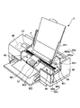
図4は、本発明の接合体を適用して得られたインクジェット式記録ヘッド(液滴吐出ヘッド)を示す分解斜視図、図5は、図4に示すインクジェット式記録ヘッドの主要部の構成を示す断面図、図6は、図4に示すインクジェット式記録ヘッドを備えるインクジェットプリンタの実施形態を示す概略図である。なお、図4は、通常使用される状態とは、上下逆に示されている。
<Droplet ejection head>
Next, an embodiment in which the joined body of the present invention is applied to an ink jet recording head will be described.
FIG. 4 is an exploded perspective view showing an ink jet recording head (droplet discharge head) obtained by applying the joined body of the present invention, and FIG. 5 shows a configuration of a main part of the ink jet recording head shown in FIG. FIG. 6 is a schematic view showing an embodiment of an ink jet printer including the ink jet recording head shown in FIG. Note that FIG. 4 is shown upside down from the state of normal use.
図4に示すインクジェット式記録ヘッド(本発明の液滴吐出ヘッド)10は、図6に示すようなインクジェットプリンタ(本発明の液滴吐出装置)9に搭載されている。
図6に示すインクジェットプリンタ9は、装置本体92を備えており、上部後方に記録用紙Pを設置するトレイ921と、下部前方に記録用紙Pを排出する排紙口922と、上部面に操作パネル97とが設けられている。
An ink jet recording head (droplet discharge head of the present invention) 10 shown in FIG. 4 is mounted on an ink jet printer (droplet discharge apparatus of the present invention) 9 as shown in FIG.
The
操作パネル97は、例えば、液晶ディスプレイ、有機ELディスプレイ、LEDランプ等で構成され、エラーメッセージ等を表示する表示部(図示せず)と、各種スイッチ等で構成される操作部(図示せず)とを備えている。
また、装置本体92の内部には、主に、往復動するヘッドユニット93を備える印刷装置(印刷手段)94と、記録用紙Pを1枚ずつ印刷装置94に送り込む給紙装置(給紙手段)95と、印刷装置94および給紙装置95を制御する制御部(制御手段)96とを有している。
The
Further, inside the apparatus
制御部96の制御により、給紙装置95は、記録用紙Pを一枚ずつ間欠送りする。この記録用紙Pは、ヘッドユニット93の下部近傍を通過する。このとき、ヘッドユニット93が記録用紙Pの送り方向とほぼ直交する方向に往復移動して、記録用紙Pへの印刷が行なわれる。すなわち、ヘッドユニット93の往復動と記録用紙Pの間欠送りとが、印刷における主走査および副走査となって、インクジェット方式の印刷が行なわれる。
Under the control of the control unit 96, the
印刷装置94は、ヘッドユニット93と、ヘッドユニット93の駆動源となるキャリッジモータ941と、キャリッジモータ941の回転を受けて、ヘッドユニット93を往復動させる往復動機構942とを備えている。
ヘッドユニット93は、その下部に、多数のノズル孔111を備えるインクジェット式記録ヘッド10(以下、単に「ヘッド10」と言う。)と、ヘッド10にインクを供給するインクカートリッジ931と、ヘッド10およびインクカートリッジ931を搭載したキャリッジ932とを有している。
The
The
なお、インクカートリッジ931として、イエロー、シアン、マゼンタ、ブラック(黒)の4色のインクを充填したものを用いることにより、フルカラー印刷が可能となる。
往復動機構942は、その両端をフレーム(図示せず)に支持されたキャリッジガイド軸943と、キャリッジガイド軸943と平行に延在するタイミングベルト944とを有している。
The
キャリッジ932は、キャリッジガイド軸943に往復動自在に支持されるとともに、タイミングベルト944の一部に固定されている。
キャリッジモータ941の作動により、プーリを介してタイミングベルト944を正逆走行させると、キャリッジガイド軸943に案内されて、ヘッドユニット93が往復動する。そして、この往復動の際に、ヘッド10から適宜インクが吐出され、記録用紙Pへの印刷が行われる。
The
When the
給紙装置95は、その駆動源となる給紙モータ951と、給紙モータ951の作動により回転する給紙ローラ952とを有している。
給紙ローラ952は、記録用紙Pの送り経路(記録用紙P)を挟んで上下に対向する従動ローラ952aと駆動ローラ952bとで構成され、駆動ローラ952bは給紙モータ951に連結されている。これにより、給紙ローラ952は、トレイ921に設置した多数枚の記録用紙Pを、印刷装置94に向かって1枚ずつ送り込めるようになっている。なお、トレイ921に代えて、記録用紙Pを収容する給紙カセットを着脱自在に装着し得るような構成であってもよい。
The
The
制御部96は、例えばパーソナルコンピュータやディジタルカメラ等のホストコンピュータから入力された印刷データに基づいて、印刷装置94や給紙装置95等を制御することにより印刷を行うものである。
制御部96は、いずれも図示しないが、主に、各部を制御する制御プログラム等を記憶するメモリ、圧電素子(振動源)14を駆動して、インクの吐出タイミングを制御する圧電素子駆動回路、印刷装置94(キャリッジモータ941)を駆動する駆動回路、給紙装置95(給紙モータ951)を駆動する駆動回路、および、ホストコンピュータからの印刷データを入手する通信回路と、これらに電気的に接続され、各部での各種制御を行うCPUとを備えている。
また、CPUには、例えば、インクカートリッジ931のインク残量、ヘッドユニット93の位置等を検出可能な各種センサ等が、それぞれ電気的に接続されている。
The control unit 96 performs printing by controlling the
Although not shown, the control unit 96 mainly includes a memory that stores a control program for controlling each unit, a piezoelectric element driving circuit that drives the piezoelectric element (vibration source) 14 to control the ink ejection timing, A driving circuit for driving the printing device 94 (carriage motor 941), a driving circuit for driving the paper feeding device 95 (paper feeding motor 951), a communication circuit for obtaining print data from the host computer, and these electrically And a CPU that is connected and performs various controls in each unit.
Further, for example, various sensors that can detect the remaining ink amount of the
制御部96は、通信回路を介して、印刷データを入手してメモリに格納する。CPUは、この印刷データを処理して、この処理データおよび各種センサからの入力データに基づいて、各駆動回路に駆動信号を出力する。この駆動信号により圧電素子14、印刷装置94および給紙装置95は、それぞれ作動する。これにより、記録用紙Pに印刷が行われる。
The control unit 96 obtains the print data via the communication circuit and stores it in the memory. The CPU processes the print data and outputs a drive signal to each drive circuit based on the process data and input data from various sensors. The piezoelectric element 14, the
以下、ヘッド10(本発明の液滴吐出ヘッド)について、図4および図5を参照しつつ詳述する。
ヘッド10は、ノズル板11と、インク室基板12と、振動板13と、振動板13に接合された圧電素子(振動源)14とを備えるヘッド本体17と、このヘッド本体17を収納する基体16とを有している。なお、このヘッド10は、オンデマンド形のピエゾジェット式ヘッドを構成する。
Hereinafter, the head 10 (the droplet discharge head of the present invention) will be described in detail with reference to FIGS.
The
ノズル板11は、例えば、SiO2、SiN、石英ガラスのようなシリコン系材料、Al、Fe、Ni、Cuまたはこれらを含む合金のような金属系材料、アルミナ、酸化鉄のような酸化物系材料、カーボンブラック、グラファイトのような炭素系材料等で構成されている。
このノズル板11には、インク滴を吐出するための多数のノズル孔111が形成されている。これらのノズル孔111間のピッチは、印刷精度に応じて適宜設定される。
The
A number of nozzle holes 111 for discharging ink droplets are formed in the
ノズル板11には、インク室基板12が固着(固定)されている。
このインク室基板12は、ノズル板11、側壁(隔壁)122および後述する振動板13により、複数のインク室(キャビティ、圧力室)121と、インクカートリッジ931から供給されるインクを貯留するリザーバ室123と、リザーバ室123から各インク室121に、それぞれインクを供給する供給口124とが区画形成されている。
An
The
各インク室121は、それぞれ短冊状(直方体状)に形成され、各ノズル孔111に対応して配設されている。各インク室121は、後述する振動板13の振動により容積可変であり、この容積変化により、インクを吐出するよう構成されている。
インク室基板12を得るための母材としては、例えば、シリコン単結晶基板、各種ガラス基板、各種樹脂基板等を用いることができる。これらの基板は、いずれも汎用的な基板であるので、これらの基板を用いることにより、ヘッド10の製造コストを低減することができる。
Each
As a base material for obtaining the
一方、インク室基板12のノズル板11と反対側には、振動板13が接合され、さらに振動板13のインク室基板12と反対側には、複数の圧電素子14が設けられている。
また、振動板13の所定位置には、振動板13の厚さ方向に貫通して連通孔131が形成されている。この連通孔131を介して、前述したインクカートリッジ931からリザーバ室123に、インクが供給可能となっている。
On the other hand, a
A
各圧電素子14は、それぞれ、下部電極142と上部電極141との間に圧電体層143を介挿してなり、各インク室121のほぼ中央部に対応して配設されている。各圧電素子14は、圧電素子駆動回路に電気的に接続され、圧電素子駆動回路の信号に基づいて作動(振動、変形)するよう構成されている。
各圧電素子14は、それぞれ、振動源として機能し、振動板13は、圧電素子14の振動により振動し、インク室121の内部圧力を瞬間的に高めるよう機能する。
基体16は、例えば各種樹脂材料、各種金属材料等で構成されており、この基体16にノズル板11が固定、支持されている。すなわち、基体16が備える凹部161に、ヘッド本体17を収納した状態で、凹部161の外周部に形成された段差162によりノズル板11の縁部を支持する。
Each piezoelectric element 14 has a
Each piezoelectric element 14 functions as a vibration source, and the
The
以上のような、ノズル板11とインク室基板12との接合、インク室基板12と振動板13との接合、およびノズル板11と基体16との接合のうち、少なくとも1箇所に本発明の接合方法が用いられている。
換言すれば、ノズル板11とインク室基板12との接合体、インク室基板12と振動板13との接合体、およびノズル板11と基体16との接合体のうち、少なくとも1箇所に本発明の接合体が適用されている。
このようなヘッド10は、上記の接合界面にプラズマ重合膜が介挿されて接合されている。このため、接合界面の接合強度および耐薬品性が高くなっており、これにより、各インク室121に貯留されたインクに対する耐久性および液密性が高くなっている。その結果、ヘッド10は、信頼性の高いものとなる。
Among the above-described bonding between the
In other words, the present invention is provided in at least one place among the joined body of the
Such a
また、非常に低温で信頼性の高い接合ができるため、線膨張係数の異なる材料でも大面積のヘッドができる点でも有利である。
また、ヘッド10の一部に本発明の接合体が適用されていると、寸法精度の高いヘッド10を構築することができる。このため、ヘッド10から吐出されたインク滴の吐出方向や、ヘッド10と記録用紙Pとの離間距離を高度に制御することができ、インクジェットプリンタ9による印字結果の品位を高めることができる。
In addition, since highly reliable bonding can be performed at a very low temperature, it is advantageous in that a large-area head can be formed even with materials having different linear expansion coefficients.
Further, when the joined body of the present invention is applied to a part of the
このようなヘッド10は、圧電素子駆動回路を介して所定の吐出信号が入力されていない状態、すなわち、圧電素子14の下部電極142と上部電極141との間に電圧が印加されていない状態では、圧電体層143に変形が生じない。このため、振動板13にも変形が生じず、インク室121には容積変化が生じない。したがって、ノズル孔111からインク滴は吐出されない。
Such a
一方、圧電素子駆動回路を介して所定の吐出信号が入力された状態、すなわち、圧電素子14の下部電極142と上部電極141との間に一定電圧が印加された状態では、圧電体層143に変形が生じる。これにより、振動板13が大きくたわみ、インク室121の容積変化が生じる。このとき、インク室121内の圧力が瞬間的に高まり、ノズル孔111からインク滴が吐出される。
On the other hand, in a state where a predetermined ejection signal is input via the piezoelectric element driving circuit, that is, in a state where a constant voltage is applied between the
1回のインクの吐出が終了すると、圧電素子駆動回路は、下部電極142と上部電極141との間への電圧の印加を停止する。これにより、圧電素子14は、ほぼ元の形状に戻り、インク室121の容積が増大する。なお、このとき、インクには、インクカートリッジ931からノズル孔111へ向かう圧力(正方向への圧力)が作用している。このため、空気がノズル孔111からインク室121へ入り込むことが防止され、インクの吐出量に見合った量のインクがインクカートリッジ931(リザーバ室123)からインク室121へ供給される。
When the ejection of one ink is completed, the piezoelectric element driving circuit stops applying the voltage between the
このようにして、ヘッド10において、印刷させたい位置の圧電素子14に、圧電素子駆動回路を介して吐出信号を順次入力することにより、任意の(所望の)文字や図形等を印刷することができる。
なお、ヘッド10は、圧電素子14の代わりに電気熱変換素子を有していてもよい。つまり、ヘッド10は、電気熱変換素子による材料の熱膨張を利用してインクを吐出する構成(いわゆる、「バブルジェット方式」(「バブルジェット」は登録商標))のものであってもよい。
In this manner, in the
The
かかる構成のヘッド10において、ノズル板11には、撥液性を付与することを目的に形成された被膜114が設けられている。これにより、ノズル孔111からインク滴が吐出される際に、このノズル孔111の周辺にインク滴が残存するのを確実に防止することができる。その結果、ノズル孔111から吐出されたインク滴を目的とする領域に確実に着弾させることができる。
In the
以上、本発明の接合方法、接合体、液滴吐出ヘッドおよび液滴吐出装置を、図示の実施形態に基づいて説明したが、本発明はこれらに限定されるものではない。
例えば、本発明の接合方法では、必要に応じて、1以上の任意の目的の工程を追加してもよい。
また、本発明の接合体は、液滴吐出ヘッド以外のものに適用可能であることは言うまでもない。具体的には、本発明の接合体は、例えば、半導体装置、MEMS、マイクロリアクタ等に適用することができる。
As described above, the bonding method, the bonded body, the droplet discharge head, and the droplet discharge apparatus of the present invention have been described based on the illustrated embodiments, but the present invention is not limited thereto.
For example, in the bonding method of the present invention, one or more optional steps may be added as necessary.
Needless to say, the joined body of the present invention is applicable to other than the droplet discharge head. Specifically, the joined body of the present invention can be applied to, for example, a semiconductor device, a MEMS, a microreactor, and the like.
次に、本発明の具体的実施例について説明する。
1.接合体の製造
以下、各実施例および各比較例では、それぞれ接合体を20個作製する。
(実施例1)
まず、第1の基材として、縦20mm×横20mm×平均厚さ1mmの単結晶シリコン基板を用意し、第2の基材として、縦20mm×横20mm×平均厚さ1mmのガラス基板を用意した。
次いで、単結晶シリコン基板(第1の基材)を図1に示すプラズマ重合装置100のチャンバー101内に収納し、酸素プラズマによる下地処理を行った。
次に、下地処理を行った面に、平均厚さ200nmのプラズマ重合膜を成膜した。なお、成膜条件は以下に示す通りである。
Next, specific examples of the present invention will be described.
1. Manufacture of bonded body In the following examples and comparative examples, 20 bonded bodies are produced.
Example 1
First, a single crystal silicon substrate having a length of 20 mm × width of 20 mm × an average thickness of 1 mm is prepared as the first base material, and a glass substrate of length 20 mm × width 20 mm × average thickness of 1 mm is prepared as the second base material. did.
Next, the single crystal silicon substrate (first base material) was accommodated in the
Next, a plasma polymerization film having an average thickness of 200 nm was formed on the surface subjected to the base treatment. The film forming conditions are as shown below.
<成膜条件>
・原料ガスの組成 :オクタメチルトリシロキサン
・原料ガスの流量 :50sccm
・キャリアガスの組成:アルゴン
・キャリアガスの流量:100sccm
・高周波電力の出力 :100W
・高周波出力密度 :25W/cm2
・チャンバー内圧力 :1Pa(低真空)
・処理時間 :15分
・基板温度 :20℃
<Film formation conditions>
-Source gas composition: Octamethyltrisiloxane-Source gas flow rate: 50 sccm
Carrier gas composition: Argon Carrier gas flow rate: 100 sccm
・ High frequency power output: 100W
・ High frequency output density: 25 W / cm 2
-Chamber pressure: 1 Pa (low vacuum)
・ Processing time: 15 minutes ・ Substrate temperature: 20 ° C.
次に、得られたプラズマ重合膜に以下に示す条件で紫外線を照射した。
<紫外線照射条件>
・雰囲気ガスの組成 :大気(空気)
・雰囲気ガスの温度 :20℃
・雰囲気ガスの圧力 :大気圧(100kPa)
・紫外線の波長 :172nm
・紫外線の照射時間 :5分
一方、ガラス基板(第2の基材)の片面に対して、酸素プラズマによる下地処理を行った。
次に、プラズマ重合膜の紫外線を照射した面と、ガラス基板の下地処理を施した面とが接触するように、単結晶シリコン基板とガラス基板とを重ね合わせた。
そして、各基材を3MPaで加圧しつつ、80℃で加熱し、15分間維持した。これにより、各基材を接合し、接合体を得た。
Next, the obtained plasma polymerization film was irradiated with ultraviolet rays under the following conditions.
<Ultraviolet irradiation conditions>
-Atmospheric gas composition: Air (air)
・ Atmospheric gas temperature: 20 ℃
・ Atmospheric gas pressure: Atmospheric pressure (100 kPa)
UV wavelength: 172 nm
-Irradiation time of ultraviolet rays: 5 minutes On the other hand, one surface of the glass substrate (second base material) was subjected to a ground treatment with oxygen plasma.
Next, the single crystal silicon substrate and the glass substrate were overlapped so that the surface of the plasma polymerization film irradiated with ultraviolet rays and the surface of the glass substrate subjected to the base treatment were in contact with each other.
And each base material was heated at 80 degreeC, pressurizing at 3 Mpa, and maintained for 15 minutes. Thereby, each base material was joined and the joined body was obtained.
(実施例2)
加熱の温度を80℃から25℃に変更した以外は、前記実施例1と同様にして接合体を得た。
(実施例3〜12)
第1の基材の構成材料および第2の基材の構成材料を、それぞれ表1に示す材料に変更した以外は、前記実施例1と同様にして接合体を得た。
(Example 2)
A joined body was obtained in the same manner as in Example 1 except that the heating temperature was changed from 80 ° C to 25 ° C.
(Examples 3 to 12)
A joined body was obtained in the same manner as in Example 1 except that the constituent material of the first base material and the constituent material of the second base material were changed to the materials shown in Table 1, respectively.
(実施例13)
高周波電力の出力を150W(高周波出力密度を37.5W/cm2)に変更した以外は、前記実施例1と同様にして接合体を得た。
(実施例14)
高周波電力の出力を200W(高周波出力密度を50W/cm2)に変更した以外は、前記実施例1と同様にして接合体を得た。
(Example 13)
A joined body was obtained in the same manner as in Example 1 except that the output of the high-frequency power was changed to 150 W (high-frequency output density was 37.5 W / cm 2 ).
(Example 14)
A joined body was obtained in the same manner as in Example 1 except that the output of the high-frequency power was changed to 200 W (high-frequency output density was 50 W / cm 2 ).
(実施例15〜17)
原料ガスを表1に示す組成のガスに変更し、プラズマ重合膜の組成を変更した以外は、それぞれ前記実施例1、3、4と同様にして接合体を得た。
(比較例1〜3)
各基材間をエポキシ系接着剤で接着した以外は、前記実施例1、3、4と同様にして、接合体を得た。
(Examples 15 to 17)
A joined body was obtained in the same manner as in Examples 1, 3, and 4 except that the raw material gas was changed to the gas having the composition shown in Table 1 and the composition of the plasma polymerized film was changed.
(Comparative Examples 1-3)
A joined body was obtained in the same manner as in Examples 1, 3 and 4 except that the substrates were bonded with an epoxy adhesive.
(比較例4)
プラズマ重合膜に代えて、以下のようにして接合膜を形成するようにした以外は、前記実施例1と同様にして、接合体を得た。
まず、シリコーン材料としてポリジメチルシロキサン骨格を有するものを含有し、溶媒としてトルエンおよびイソブタノールを含有する液状材料(信越化学工業社製、「KR−251」:粘度(25℃)18.0mPa・s)を用意した。
(Comparative Example 4)
A joined body was obtained in the same manner as in Example 1 except that instead of the plasma polymerized film, a joined film was formed as follows.
First, a liquid material containing a polydimethylsiloxane skeleton as a silicone material and containing toluene and isobutanol as a solvent (“KR-251” manufactured by Shin-Etsu Chemical Co., Ltd .: viscosity (25 ° C.) 18.0 mPa · s ) Was prepared.
次いで、単結晶シリコン基板の表面に酸素プラズマによる表面処理を行った後、この面に液状材料を塗布した。
次いで、得られた液状被膜を常温(25℃)で24時間乾燥させた。これにより、接合膜を得た。
また、これと同様にして、ガラス基板に酸素プラズマによる表面処理を行った後、この面に接合膜を得た。
そして、各接合膜の周縁部の幅3mmの枠状の領域に選択的に紫外線を照射した。
次いで、接合膜同士が密着するようにシリコン基板とガラス基板とを加圧しつつ加熱した。これにより、シリコン基板とガラス基板とが接合膜を介して接合された接合体を得た。
Next, the surface of the single crystal silicon substrate was subjected to surface treatment with oxygen plasma, and then a liquid material was applied to this surface.
Next, the obtained liquid film was dried at room temperature (25 ° C.) for 24 hours. Thereby, a bonding film was obtained.
In the same manner, a surface treatment using oxygen plasma was performed on the glass substrate, and then a bonding film was obtained on this surface.
And the ultraviolet-ray was selectively irradiated to the frame-shaped area | region of width 3mm of the peripheral part of each bonding film.
Next, the silicon substrate and the glass substrate were heated while being pressed so that the bonding films were in close contact with each other. Thus, a bonded body in which the silicon substrate and the glass substrate were bonded via the bonding film was obtained.
(比較例5〜10)
第1の基材の構成材料および第2の基材の構成材料を、それぞれ表1に示す材料に変更した以外は、前記比較例4と同様にして接合体を得た。
(比較例11)
プラズマ重合膜に代えて、以下のようにして接合膜を形成するようにした以外は、前記実施例1と同様にして、接合体を得た。
まず、単結晶シリコン基板の表面に酸素プラズマによる表面処理を行った後、この面の周縁部の幅3mmの枠状の領域に選択的にヘキサメチルジシラザン(HMDS)の蒸気をあてることによって、HMDSで構成された接合膜を得た。
また、これと同様にして、ガラス基板に酸素プラズマによる表面処理を行った後、この面にHMDSで構成された接合膜を得た。
そして、各接合膜の周縁部の幅3mmの枠状の領域に選択的に紫外線を照射した。
次いで、接合膜同士が密着するようにシリコン基板とガラス基板とを加圧しつつ加熱した。これにより、シリコン基板とガラス基板とが接合膜を介して接合された接合体を得た。
(Comparative Examples 5 to 10)
A joined body was obtained in the same manner as in Comparative Example 4 except that the constituent material of the first base material and the constituent material of the second base material were changed to the materials shown in Table 1, respectively.
(Comparative Example 11)
A joined body was obtained in the same manner as in Example 1 except that instead of the plasma polymerized film, a joined film was formed as follows.
First, after performing surface treatment with oxygen plasma on the surface of the single crystal silicon substrate, by selectively applying a hexamethyldisilazane (HMDS) vapor to a frame-like region having a width of 3 mm at the peripheral portion of this surface, A bonding film composed of HMDS was obtained.
In the same manner, the glass substrate was subjected to surface treatment with oxygen plasma, and then a bonding film made of HMDS was obtained on this surface.
And the ultraviolet-ray was selectively irradiated to the frame-shaped area | region of width 3mm of the peripheral part of each bonding film.
Next, the silicon substrate and the glass substrate were heated while being pressed so that the bonding films were in close contact with each other. Thus, a bonded body in which the silicon substrate and the glass substrate were bonded via the bonding film was obtained.
2.接合体の評価
2.1 接合強度(割裂強度)の評価
各実施例および各比較例で得られた接合体について、それぞれ接合強度を測定した。
接合強度の測定は、各基材を引き剥がしたとき、剥がれる直前の強度を測定することにより行った。また、接合強度の測定は、接合直後と、接合後に−40℃〜125℃の温度サイクルを100回繰り返した後のそれぞれにおいて行った。そして、接合強度を以下の基準にしたがって評価した。
2. 2. Evaluation of Bonded Body 2.1 Evaluation of Bonding Strength (Split Strength) The bonding strength was measured for each of the bonded bodies obtained in each Example and each Comparative Example.
The measurement of the bonding strength was performed by measuring the strength immediately before each substrate was peeled off. Further, the measurement of the bonding strength was performed immediately after bonding and after repeating the temperature cycle of −40 ° C. to 125 ° C. 100 times after bonding. Then, the bonding strength was evaluated according to the following criteria.
<接合強度の評価基準>
◎:10MPa(100kgf/cm2)以上
○: 5MPa( 50kgf/cm2)以上、10MPa(100kgf/cm2)未満
△: 1MPa( 10kgf/cm2)以上、 5MPa( 50kgf/cm2)未満
×: 1MPa( 10kgf/cm2)未満
<Evaluation criteria for bonding strength>
◎: 10 MPa (100 kgf / cm 2 ) or more ○: 5 MPa (50 kgf / cm 2 ) or more, less than 10 MPa (100 kgf / cm 2 ) Δ: 1 MPa (10 kgf / cm 2 ) or more, less than 5 MPa (50 kgf / cm 2 ) ×: Less than 1 MPa (10 kgf / cm 2 )
2.2 寸法精度の評価
各実施例および各比較例で得られた接合体について、それぞれ厚さ方向の寸法精度を測定した。
寸法精度の測定は、正方形の接合体の各角部の厚さを測定し、4箇所の厚さの最大値と最小値の差を算出することにより行った。そして、この差を以下の基準にしたがって評価した。
<寸法精度の評価基準>
○:10μm未満
×:10μm以上
2.2 Evaluation of dimensional accuracy The dimensional accuracy in the thickness direction was measured for each joined body obtained in each of the examples and the comparative examples.
The measurement of the dimensional accuracy was performed by measuring the thickness of each corner of the square joined body and calculating the difference between the maximum value and the minimum value of the thicknesses at the four locations. This difference was evaluated according to the following criteria.
<Evaluation criteria for dimensional accuracy>
○: Less than 10 μm ×: 10 μm or more
2.3 耐薬品性の評価
各実施例および各比較例で得られた接合体のうち各10個を、80℃に維持したインクジェットプリンタ用インク(エプソン社製、HQ4)に、以下の条件で3週間浸漬した。また、接合体の残りの10個を、同様のインクに50日間浸漬した。そして、各基材を引き剥がし、接合界面にインクが浸入していないかを確認した。そして、その結果を以下の基準にしたがって評価した。
2.3 Evaluation of chemical resistance Ten of each of the joined bodies obtained in each Example and each Comparative Example were applied to an ink for an inkjet printer maintained at 80 ° C. (HQ4, manufactured by Epson Corporation) under the following conditions. Soaked for 3 weeks. Further, the remaining 10 joined bodies were immersed in the same ink for 50 days. And each base material was peeled off and it was confirmed whether the ink permeated into the joining interface. The results were evaluated according to the following criteria.
<耐薬品性の評価基準>
◎:全く浸入していない
○:角部にわずかに浸入している
△:縁部に沿って浸入している
×:内側に浸入している
<Evaluation criteria for chemical resistance>
◎: Not penetrated at all ○: Slightly penetrated into the corner △: Infiltrated along the edge ×: Intruded inside
2.4 赤外線吸収(FT−IR)の評価
各実施例および各比較例で得られた接合体中の接合膜について、それぞれ赤外光吸収スペクトルを取得した。そして、各スペクトルについて、(1)シロキサン(Si−O)結合に帰属するピークに対するSi−H結合に帰属するピークの相対強度と、(2)シロキサン結合に帰属するピークに対するメチル基に帰属するピークの相対強度とを算出した。
2.4 Evaluation of Infrared Absorption (FT-IR) An infrared light absorption spectrum was obtained for each bonding film in the bonded body obtained in each Example and each Comparative Example. For each spectrum, (1) the relative intensity of the peak attributed to the Si—H bond relative to the peak attributed to the siloxane (Si—O) bond, and (2) the peak attributed to the methyl group relative to the peak attributed to the siloxane bond. Relative intensity was calculated.
2.5 屈折率の評価
各実施例および各比較例で得られた接合体中の接合膜について、それぞれ屈折率を測定した。
2.6 光透過率の評価
各実施例および各比較例で得られた接合体のうち、光透過率の測定が可能なものについて、光透過率を測定した。そして、得られた光透過率を以下の評価基準にしたがって評価した。
<光透過率の評価基準>
◎:95%超
○:90%超95%未満
△:85%超90%未満
×:85%未満
以上、2.1〜2.6の各評価結果を表1に示す。
2.5 Evaluation of Refractive Index The refractive index of each bonding film in the bonded body obtained in each example and each comparative example was measured.
2.6 Evaluation of light transmittance Among the joined bodies obtained in each of the examples and the comparative examples, the light transmittance was measured for those that can measure the light transmittance. And the obtained light transmittance was evaluated according to the following evaluation criteria.
<Evaluation criteria for light transmittance>
A: More than 95% B: More than 90% and less than 95% Δ: More than 85% and less than 90% ×: Less than 85% The evaluation results of 2.1 to 2.6 are shown in Table 1.

表1から明らかなように、各実施例で得られた接合体は、接合強度、寸法精度および耐薬品性のいずれの項目においても優れた特性を示した。
一方、各比較例で得られた接合体は、接合強度および耐薬品性が十分ではなかった。また、寸法精度は、特に低いことが認められた。
As is clear from Table 1, the joined bodies obtained in each Example exhibited excellent characteristics in all items of joining strength, dimensional accuracy, and chemical resistance.
On the other hand, the joined body obtained in each comparative example was not sufficient in joining strength and chemical resistance. Also, it was recognized that the dimensional accuracy was particularly low.
1……接合体 21……第1の基材 22……第2の基材 23……接合面 3……プラズマ重合膜 31……表面 100……プラズマ重合装置 101……チャンバー 102……接地線 103……供給口 104……排気口 130……第1の電極 139……静電チャック 140……第2の電極 170……ポンプ 171……圧力制御機構 180……電源回路 182……高周波電源 183……マッチングボックス 184……配線 190……ガス供給部 191……貯液部 192……気化装置 193……ガスボンベ 194……配管 195……拡散板 10……インクジェット式記録ヘッド 11……ノズル板 111……ノズル孔 114……被膜 12……インク室基板 121……インク室 122……側壁 123……リザーバ室 124……供給口 13……振動板 131……連通孔 14……圧電素子 141……上部電極 142……下部電極 143……圧電体層 16……基体 161……凹部 162……段差 17……ヘッド本体 9……インクジェットプリンタ 92……装置本体 921……トレイ 922……排紙口 93……ヘッドユニット 931……インクカートリッジ 932……キャリッジ 94……印刷装置 941……キャリッジモータ 942……往復動機構 943……キャリッジガイド軸 944……タイミングベルト 95……給紙装置 951……給紙モータ 952……給紙ローラ 952a……従動ローラ 952b……駆動ローラ 96……制御部 97……操作パネル P……記録用紙
DESCRIPTION OF
Claims (4)
前記プラズマ重合膜の表面にエネルギーを付与して、該プラズマ重合膜の表面を活性化させる第2の工程と、
少なくとも前記第1の被着体と接合される面にプラズマ重合膜を備えない第2の被着体を用意し、前記活性化させたプラズマ重合膜の表面と前記第2の被着体とを密着させるように、前記第1の被着体と前記第2の被着体とを貼り合わせ、接合体を得る第3の工程とを有することを特徴とする接合方法。 A first step of preparing a first adherend comprising a plasma polymerized film composed mainly of an organometallic polymer composed mainly of a polymer of trimethylgallium or trimethylaluminum on a substrate;
A second step of applying energy to the surface of the plasma polymerized film to activate the surface of the plasma polymerized film;
A second adherend having no plasma polymerized film is prepared at least on a surface to be bonded to the first adherend, and the activated surface of the plasma polymerized film and the second adherend are prepared. A bonding method comprising: a third step of bonding the first adherend and the second adherend to obtain a bonded body so as to be in close contact with each other.
トリメチルガリウムまたはトリメチルアルミニウムの重合物を主成分とする有機金属ポリマーを主材料とするプラズマ重合膜と、を有し、
前記第1の基材上に設けられた前記プラズマ重合膜を介して、前記第1の基材と前記第2の基材とが接合されていることを特徴とする接合体。 A first substrate and a second substrate ;
A plasma polymerized film of an organic metal polymer over which the door trimethyl gallium or polymer of trimethyl aluminum as its main component as a main material, and
The joined body, wherein the first base material and the second base material are joined via the plasma polymerized film provided on the first base material.
Priority Applications (5)
| Application Number | Priority Date | Filing Date | Title |
|---|---|---|---|
| JP2008145158A JP4670905B2 (en) | 2007-06-18 | 2008-06-02 | Bonding method, bonded body, droplet discharge head, and droplet discharge apparatus |
| US12/665,259 US20100200144A1 (en) | 2007-06-18 | 2008-06-16 | Bonding method, bonded body, droplet ejection head, and droplet ejection apparatus |
| KR1020097025697A KR101123261B1 (en) | 2007-06-18 | 2008-06-16 | Bonding method, bonded body, droplet ejection head, and droplet ejection device |
| PCT/JP2008/060987 WO2008156057A1 (en) | 2007-06-18 | 2008-06-16 | Bonding method, bonded body, droplet ejection head, and droplet ejection device |
| CN200880020534A CN101688083A (en) | 2007-06-18 | 2008-06-16 | Bonding method, bonded body, droplet ejection head, and droplet ejection device |
Applications Claiming Priority (2)
| Application Number | Priority Date | Filing Date | Title |
|---|---|---|---|
| JP2007160797 | 2007-06-18 | ||
| JP2008145158A JP4670905B2 (en) | 2007-06-18 | 2008-06-02 | Bonding method, bonded body, droplet discharge head, and droplet discharge apparatus |
Related Child Applications (1)
| Application Number | Title | Priority Date | Filing Date |
|---|---|---|---|
| JP2010102352A Division JP2010184499A (en) | 2007-06-18 | 2010-04-27 | Bonding process, bonded body, liquid droplet discharge head and liquid droplet discharge apparatus |
Publications (2)
| Publication Number | Publication Date |
|---|---|
| JP2009023338A JP2009023338A (en) | 2009-02-05 |
| JP4670905B2 true JP4670905B2 (en) | 2011-04-13 |
Family
ID=40395621
Family Applications (2)
| Application Number | Title | Priority Date | Filing Date |
|---|---|---|---|
| JP2008145158A Expired - Fee Related JP4670905B2 (en) | 2007-06-18 | 2008-06-02 | Bonding method, bonded body, droplet discharge head, and droplet discharge apparatus |
| JP2010102352A Withdrawn JP2010184499A (en) | 2007-06-18 | 2010-04-27 | Bonding process, bonded body, liquid droplet discharge head and liquid droplet discharge apparatus |
Family Applications After (1)
| Application Number | Title | Priority Date | Filing Date |
|---|---|---|---|
| JP2010102352A Withdrawn JP2010184499A (en) | 2007-06-18 | 2010-04-27 | Bonding process, bonded body, liquid droplet discharge head and liquid droplet discharge apparatus |
Country Status (4)
| Country | Link |
|---|---|
| US (1) | US20100200144A1 (en) |
| JP (2) | JP4670905B2 (en) |
| KR (1) | KR101123261B1 (en) |
| CN (1) | CN101688083A (en) |
Families Citing this family (4)
| Publication number | Priority date | Publication date | Assignee | Title |
|---|---|---|---|---|
| JP5541056B2 (en) * | 2010-10-01 | 2014-07-09 | セイコーエプソン株式会社 | Polarization conversion element, polarization conversion unit, projection device, and method of manufacturing polarization conversion element |
| JP2014156604A (en) * | 2014-03-26 | 2014-08-28 | Seiko Epson Corp | Joined body |
| CN109698285A (en) * | 2017-10-23 | 2019-04-30 | 昆山维信诺科技有限公司 | Bonding method, mechanism and the display panel of thin-film packing structure and the film that blocks water |
| JP7256481B2 (en) | 2018-03-09 | 2023-04-12 | コニカミノルタ株式会社 | Structure manufacturing method |
Citations (5)
| Publication number | Priority date | Publication date | Assignee | Title |
|---|---|---|---|---|
| JPH01207475A (en) * | 1988-02-10 | 1989-08-21 | Kuraray Co Ltd | Production of polyester cloth |
| JPH05194770A (en) * | 1992-01-17 | 1993-08-03 | Mitsubishi Kasei Corp | Surface-coated plastic article |
| JPH0766549A (en) * | 1993-08-23 | 1995-03-10 | Matsushita Electric Works Ltd | Joining method for metal and organic substance, and manufacture of wiring board |
| JP2002524597A (en) * | 1998-09-04 | 2002-08-06 | サイムド ライフ システムズ, インコーポレイテッド | Method for attaching a polymer and a medical device comprising a material attached by this method |
| JP2009035720A (en) * | 2007-07-11 | 2009-02-19 | Seiko Epson Corp | Substrate with joining film, joining method and joined product |
Family Cites Families (12)
| Publication number | Priority date | Publication date | Assignee | Title |
|---|---|---|---|---|
| JP2585006B2 (en) * | 1987-07-22 | 1997-02-26 | 東レ・ダウコーニング・シリコーン株式会社 | Resin-sealed semiconductor device and method of manufacturing the same |
| US5019210A (en) * | 1989-04-03 | 1991-05-28 | International Business Machines Corporation | Method for enhancing the adhesion of polymer surfaces by water vapor plasma treatment |
| JP2929651B2 (en) * | 1990-03-14 | 1999-08-03 | 株式会社ブリヂストン | Method for producing rubber-based composite material |
| US5283086A (en) * | 1992-12-23 | 1994-02-01 | The University Of Western Ontario | Plasma treatment of polymer powders |
| US6764812B1 (en) * | 1996-06-25 | 2004-07-20 | Ronald M. Kubacki | Plasma deposited selective wetting material |
| US6287990B1 (en) * | 1998-02-11 | 2001-09-11 | Applied Materials, Inc. | CVD plasma assisted low dielectric constant films |
| US6420032B1 (en) * | 1999-03-17 | 2002-07-16 | General Electric Company | Adhesion layer for metal oxide UV filters |
| US6716770B2 (en) * | 2001-05-23 | 2004-04-06 | Air Products And Chemicals, Inc. | Low dielectric constant material and method of processing by CVD |
| JP4027072B2 (en) * | 2001-10-18 | 2007-12-26 | 松下電器産業株式会社 | Low pressure plasma processing apparatus and method |
| JP4293035B2 (en) * | 2003-05-07 | 2009-07-08 | セイコーエプソン株式会社 | Liquid repellent film covering member, component of liquid ejection device, nozzle plate of liquid ejection head, liquid ejection head, and liquid ejection device |
| EP1615260A3 (en) * | 2004-07-09 | 2009-09-16 | JSR Corporation | Organic silicon-oxide-based film, composition and method for forming the same, and semiconductor device |
| US7517561B2 (en) * | 2005-09-21 | 2009-04-14 | Ford Global Technologies, Llc | Method of coating a substrate for adhesive bonding |
-
2008
- 2008-06-02 JP JP2008145158A patent/JP4670905B2/en not_active Expired - Fee Related
- 2008-06-16 US US12/665,259 patent/US20100200144A1/en not_active Abandoned
- 2008-06-16 KR KR1020097025697A patent/KR101123261B1/en active IP Right Grant
- 2008-06-16 CN CN200880020534A patent/CN101688083A/en active Pending
-
2010
- 2010-04-27 JP JP2010102352A patent/JP2010184499A/en not_active Withdrawn
Patent Citations (5)
| Publication number | Priority date | Publication date | Assignee | Title |
|---|---|---|---|---|
| JPH01207475A (en) * | 1988-02-10 | 1989-08-21 | Kuraray Co Ltd | Production of polyester cloth |
| JPH05194770A (en) * | 1992-01-17 | 1993-08-03 | Mitsubishi Kasei Corp | Surface-coated plastic article |
| JPH0766549A (en) * | 1993-08-23 | 1995-03-10 | Matsushita Electric Works Ltd | Joining method for metal and organic substance, and manufacture of wiring board |
| JP2002524597A (en) * | 1998-09-04 | 2002-08-06 | サイムド ライフ システムズ, インコーポレイテッド | Method for attaching a polymer and a medical device comprising a material attached by this method |
| JP2009035720A (en) * | 2007-07-11 | 2009-02-19 | Seiko Epson Corp | Substrate with joining film, joining method and joined product |
Also Published As
| Publication number | Publication date |
|---|---|
| KR101123261B1 (en) | 2012-03-20 |
| KR20100019494A (en) | 2010-02-18 |
| CN101688083A (en) | 2010-03-31 |
| JP2010184499A (en) | 2010-08-26 |
| JP2009023338A (en) | 2009-02-05 |
| US20100200144A1 (en) | 2010-08-12 |
Similar Documents
| Publication | Publication Date | Title |
|---|---|---|
| JP4687747B2 (en) | Joining method | |
| JP4337935B2 (en) | Bonded body and bonding method | |
| JP4710897B2 (en) | Separation method of joined body | |
| JP4697253B2 (en) | Bonding method, droplet discharge head, bonded body, and droplet discharge apparatus | |
| JP2009028922A (en) | Joining method, joint article, droplet ejection head and droplet ejection device | |
| JP5625470B2 (en) | Joining method | |
| JP4674619B2 (en) | Nozzle plate, nozzle plate manufacturing method, droplet discharge head, and droplet discharge apparatus | |
| JP2010275423A (en) | Bonding method and bonded body | |
| JP4608629B2 (en) | Nozzle plate, nozzle plate manufacturing method, droplet discharge head, droplet discharge head manufacturing method, and droplet discharge apparatus | |
| JP2010095595A (en) | Bonding method and bonded body | |
| JP4670905B2 (en) | Bonding method, bonded body, droplet discharge head, and droplet discharge apparatus | |
| JP2008307873A (en) | Bonding method, bonding body, droplet discharge head, and droplet discharge apparatus | |
| JP2010106079A (en) | Joining method and joined body | |
| JP2010189518A (en) | Bonding method and bonded article | |
| JP2010095594A (en) | Bonding method and bonded body | |
| JP2009143992A (en) | Joining method and joined body | |
| JP2009248368A (en) | Joined article and method for peeling joined article | |
| JP2009028921A (en) | Joining method, joint article, droplet ejection head and droplet ejection device | |
| JP2009028920A (en) | Joining method, joined body, liquid droplet ejecting head and liquid droplet ejector | |
| JP2010040877A (en) | Bonding method, junction structure, droplet discharge head and droplet discharging device | |
| JP2014141602A (en) | Bonding film for bonding substrate with other substrate, method of forming bonding film, bonded body, liquid droplet ejecting head, and apparatus for ejecting liquid droplet | |
| JP2009285886A (en) | Base material with bonding film and bonded body | |
| JP2010280229A (en) | Nozzle plate, method for manufacturing nozzle plate, droplet discharge head, method for manufacturing droplet discharge head, and droplet discharge device | |
| JP2010030048A (en) | Method for manufacturing liquid droplet ejection head | |
| JP2011256286A (en) | Substrate with joint membrane, joining method, and joined assembly |
Legal Events
| Date | Code | Title | Description |
|---|---|---|---|
| A131 | Notification of reasons for refusal |
Free format text: JAPANESE INTERMEDIATE CODE: A131 Effective date: 20100302 |
|
| A521 | Request for written amendment filed |
Free format text: JAPANESE INTERMEDIATE CODE: A523 Effective date: 20100427 |
|
| A02 | Decision of refusal |
Free format text: JAPANESE INTERMEDIATE CODE: A02 Effective date: 20100629 |
|
| A521 | Request for written amendment filed |
Free format text: JAPANESE INTERMEDIATE CODE: A523 Effective date: 20100927 |
|
| A911 | Transfer to examiner for re-examination before appeal (zenchi) |
Free format text: JAPANESE INTERMEDIATE CODE: A911 Effective date: 20101006 |
|
| TRDD | Decision of grant or rejection written | ||
| A01 | Written decision to grant a patent or to grant a registration (utility model) |
Free format text: JAPANESE INTERMEDIATE CODE: A01 Effective date: 20101221 |
|
| A01 | Written decision to grant a patent or to grant a registration (utility model) |
Free format text: JAPANESE INTERMEDIATE CODE: A01 |
|
| A61 | First payment of annual fees (during grant procedure) |
Free format text: JAPANESE INTERMEDIATE CODE: A61 Effective date: 20110103 |
|
| R150 | Certificate of patent or registration of utility model |
Ref document number: 4670905 Country of ref document: JP Free format text: JAPANESE INTERMEDIATE CODE: R150 Free format text: JAPANESE INTERMEDIATE CODE: R150 |
|
| FPAY | Renewal fee payment (event date is renewal date of database) |
Free format text: PAYMENT UNTIL: 20140128 Year of fee payment: 3 |
|
| S531 | Written request for registration of change of domicile |
Free format text: JAPANESE INTERMEDIATE CODE: R313531 |
|
| R350 | Written notification of registration of transfer |
Free format text: JAPANESE INTERMEDIATE CODE: R350 |
|
| LAPS | Cancellation because of no payment of annual fees |