JP4670710B2 - Engine starter - Google Patents
Engine starter Download PDFInfo
- Publication number
- JP4670710B2 JP4670710B2 JP2006100945A JP2006100945A JP4670710B2 JP 4670710 B2 JP4670710 B2 JP 4670710B2 JP 2006100945 A JP2006100945 A JP 2006100945A JP 2006100945 A JP2006100945 A JP 2006100945A JP 4670710 B2 JP4670710 B2 JP 4670710B2
- Authority
- JP
- Japan
- Prior art keywords
- engine
- cylinder
- time
- starter
- compression
- Prior art date
- Legal status (The legal status is an assumption and is not a legal conclusion. Google has not performed a legal analysis and makes no representation as to the accuracy of the status listed.)
- Expired - Fee Related
Links
Images


Classifications
-
- Y—GENERAL TAGGING OF NEW TECHNOLOGICAL DEVELOPMENTS; GENERAL TAGGING OF CROSS-SECTIONAL TECHNOLOGIES SPANNING OVER SEVERAL SECTIONS OF THE IPC; TECHNICAL SUBJECTS COVERED BY FORMER USPC CROSS-REFERENCE ART COLLECTIONS [XRACs] AND DIGESTS
- Y02—TECHNOLOGIES OR APPLICATIONS FOR MITIGATION OR ADAPTATION AGAINST CLIMATE CHANGE
- Y02T—CLIMATE CHANGE MITIGATION TECHNOLOGIES RELATED TO TRANSPORTATION
- Y02T10/00—Road transport of goods or passengers
- Y02T10/10—Internal combustion engine [ICE] based vehicles
- Y02T10/12—Improving ICE efficiencies
-
- Y—GENERAL TAGGING OF NEW TECHNOLOGICAL DEVELOPMENTS; GENERAL TAGGING OF CROSS-SECTIONAL TECHNOLOGIES SPANNING OVER SEVERAL SECTIONS OF THE IPC; TECHNICAL SUBJECTS COVERED BY FORMER USPC CROSS-REFERENCE ART COLLECTIONS [XRACs] AND DIGESTS
- Y02—TECHNOLOGIES OR APPLICATIONS FOR MITIGATION OR ADAPTATION AGAINST CLIMATE CHANGE
- Y02T—CLIMATE CHANGE MITIGATION TECHNOLOGIES RELATED TO TRANSPORTATION
- Y02T10/00—Road transport of goods or passengers
- Y02T10/10—Internal combustion engine [ICE] based vehicles
- Y02T10/40—Engine management systems
Description
本発明は、一時的に停止状態にあるエンジンを、その後自動的に始動させるエンジンの始動装置に関するものである。 The present invention relates to an engine starter that automatically starts an engine that is temporarily stopped.
近年、燃費低減およびCO2排出量の抑制等を図るため、アイドル時にエンジンを自動的にいったん停止させるとともに、その後に発進操作等の再始動条件が成立したときにエンジンを自動的に再始動させるようにしたエンジンの始動装置が開発されてきている。 In recent years, in order to reduce fuel consumption and reduce CO2 emissions, the engine is automatically stopped once during idling, and then automatically restarted when a restart condition such as a start operation is established. An engine starter has been developed.
このエンジンの再始動は、再始動条件成立に応じて即座に始動させることが要求されるため、スタータ(始動用のモータ)によりエンジン出力軸を駆動するクランキングを経てエンジンを始動させるような、始動完了までにかなりの時間を要する従来の一般的な始動方法は好ましくない。 This restart of the engine is required to start immediately according to the establishment of the restart condition, so that the engine is started through cranking that drives the engine output shaft by a starter (starting motor), The conventional general starting method which requires a considerable time to complete the starting is not preferable.
そこで、停止状態のエンジンの膨張行程にある気筒(以下、エンジン停止時に膨張行程にある気筒を便宜上停止時膨脹行程気筒と称する。他の行程にある気筒も同様である)に燃料を供給して燃焼を行わせ、そのエネルギーでエンジンが即時的に始動されるようにする始動方法が開発されつつある。 Therefore, fuel is supplied to a cylinder in the expansion stroke of the engine in a stopped state (hereinafter, a cylinder in the expansion stroke when the engine is stopped is referred to as a “expansion stroke in the stop stroke for convenience. The same applies to cylinders in other strokes). Starting methods are being developed that allow combustion to occur and the engine to be started immediately with that energy.
しかし、このような燃焼のみによる始動方法は、スタータを用いた始動方法ほど確実でないのが実情である。そこで、燃焼のみによる始動が不調に終わったとき、または不調に終わると予測される状態となったとき、スタータの補助を受けて始動するものが考えられている(いわゆるバックアップ始動)。 However, in reality, such a starting method using only combustion is not as reliable as a starting method using a starter. In view of this, it is conceivable to start with the aid of a starter when the start by combustion alone ends abnormally or when it is predicted to end abnormally (so-called backup start).
例えば特許文献1には、燃焼のみによる始動を行った後の所定の検査タイミングでバックアップ始動の要否を判定し、必要に応じてこれを行うものが開示されている。
For example,
一方、燃焼のみによる始動方法を不調に終わらせる要因のひとつに、いわゆる温間ロックがある。温間ロックとは、気筒内が高温、高圧となることにより、圧縮行程で自着火が起きる現象である。温間ロックが起こると逆向きのトルクが発生するので、始動性に悪影響を及ぼす。 On the other hand, there is a so-called warm lock as one of the factors that end the start method by combustion alone. Warm lock is a phenomenon in which self-ignition occurs in the compression stroke due to high temperature and high pressure in the cylinder. When warm lock occurs, reverse torque is generated, which adversely affects startability.
例えば特許文献2には、エンジン停止時に吸気行程にある気筒が最初の圧縮行程を迎えたとき(このときの温間ロックが最も懸念される)、その圧縮行程の気筒内に燃料を供給し、その気化潜熱によって温度と圧力を低減させ、自着火を抑制するものが開示されている。
しかしながら、特許文献1に記載のバックアップ始動制御を行うような場合には、特許文献2に記載の温間ロック対策が有効に作用しないという問題がある。バックアップ始動制御を行う場合には、温間ロックが問題となるタイミングが大きく遅れるからである。
However, when the backup start control described in
しかも、バックアップ始動制御が必要と判定されるタイミングは、既に温間ロック対策の燃料供給がなされた後なので、それを修復することが困難である。 In addition, since it is determined that the backup start control is necessary after the fuel supply for the warm lock has already been performed, it is difficult to repair it.
本発明は、上記の事情に鑑みてなされたものであり、的確にバックアップ始動制御を行うとともに、その場合にも有効な温間ロック対策を行うことができるエンジンの始動装置を提供することを目的とする。 The present invention has been made in view of the above circumstances, and it is an object of the present invention to provide an engine starter capable of accurately performing backup start control and effectively taking measures against warm lock even in that case. And
上記課題を解決するための請求項1に係る発明は、一時的に停止状態にあるエンジンに所定の再始動条件が成立したときに、少なくともエンジン停止時に膨張行程にある気筒で燃焼を行わせて自動的に再始動させる自動再始動制御を行う再始動制御手段を備えたエンジンの始動装置であって、エンジンに正転方向の駆動力を付与するスタータモータと、吸気弁の少なくとも閉弁時期を遅角可能な可変バルブタイミング機構とを備え、上記再始動制御手段は、上記自動再始動制御において、所定時期に上記スタータモータを駆動させるバックアップ始動制御を必要に応じて行うように構成され、上記バックアップ始動制御は、始動後の第1圧縮上死点でその要否が判別されるものであって、エンジンの回転が第2圧縮上死点を越えられないと判別されたときに必要と判定され、上記再始動制御手段は、上記バックアップ始動制御を行わないとき、エンジン停止時に吸気行程にある気筒の、最初の圧縮行程での特定燃料供給を実行し、上記再始動制御手段は、上記バックアップ始動制御を行うとき、上記特定燃料供給を禁止するとともに、その後エンジンが逆転を始めると、上記スタータモータを、エンジンが逆転から正転に転じる付近のタイミングで駆動力付与がなされるように駆動し、上記特定燃料供給を禁止した気筒で上記スタータモータの駆動による再圧縮がなされるときに、その再圧縮の開始後の圧縮行程途中まで吸気弁の閉弁時期を遅角させ、該吸気弁の閉弁後の圧縮行程において該気筒に燃料を供給することを特徴とする。
According to a first aspect of the present invention for solving the above problem, when a predetermined restart condition is established in an engine that is temporarily stopped, combustion is performed in a cylinder that is in an expansion stroke at least when the engine is stopped. An engine starter having restart control means for performing automatic restart control for automatically restarting, comprising: a starter motor that applies a driving force in the normal rotation direction to the engine; and at least a closing timing of the intake valve A variable valve timing mechanism capable of retarding, wherein the restart control means is configured to perform backup start control for driving the starter motor at a predetermined time in the automatic restart control as required, backup start control is a one whose necessity is determined in the first compression TDC after startup, when the rotation of the engine can not exceed the second compression TDC determine The restart control means executes the specific fuel supply in the first compression stroke of the cylinder in the intake stroke when the engine is stopped when the backup start control is not performed. The start control means prohibits the supply of the specific fuel when performing the backup start control, and applies the driving force to the starter motor at a timing in the vicinity of the engine turning from the reverse rotation to the normal rotation when the engine starts reverse rotation thereafter. When re-compression is performed by driving the starter motor in a cylinder in which the specific fuel supply is prohibited, the intake valve closing timing is delayed until the middle of the compression stroke after the start of re-compression. In the compression stroke after the intake valve is closed, fuel is supplied to the cylinder.
ここで、第1圧縮上死点(第1TDC)、第2圧縮上死点(第2TDC)・・・とは、特定の気筒の圧縮上死点を指すわけではなく、正回転後に、何れかの気筒で圧縮上死点を経過したら、それを順番にカウントするものである。 Here, the first compression top dead center (first TDC), the second compression top dead center (second TDC)... Does not indicate the compression top dead center of a specific cylinder, and is either after the forward rotation. When the compression top dead center has elapsed in the cylinder, the count is sequentially performed.
請求項2に係る発明は、請求項1記載のエンジンの始動装置において、上記再始動制御手段は、最初にエンジン停止時に圧縮行程にある気筒で燃焼を行わせて一旦エンジンを逆転させた後、上記エンジン停止時に膨張行程にある気筒での最初の燃焼を行なわせることを特徴とする。 According to a second aspect of the present invention, in the engine starting device according to the first aspect, the restart control means first performs combustion in the cylinder in the compression stroke when the engine is stopped, and once reverses the engine, The first combustion is performed in the cylinder in the expansion stroke when the engine is stopped.
請求項3に係る発明は、請求項2記載のエンジンの始動装置において、上記再始動制御手段は、上記エンジン逆転後の最初の燃焼を行わせ、その後2回目の逆転が起きたときに、その2回目の逆転中の行程の略中間点を起算点として、2回目の逆転の開始時から上記起算点に至るまでの時間から上記スタータモータの遅れ時間を差し引いた時間だけ経過した時点を、上記スタータモータの駆動開始時期として算出することを特徴とする。
According to a third aspect of the present invention, in the engine starter according to the second aspect , the restart control means performs the first combustion after the engine reverse rotation, and then when the second reverse rotation occurs, a second time counting point substantially midpoint of stroke in reversal, the point at which the time from the start up to the above starting point has elapsed by the time obtained by subtracting the delay time of the starter motor of the second reversal, the It is calculated as the drive start time of the starter motor .
請求項4に係る発明は、請求項1乃至3の何れか1項に記載のエンジンの始動装置において、エンジンの温度状態を検出するエンジン温度検出手段を備え、上記可変バルブタイミング機構は電磁力で開閉駆動する電磁式動弁機構であって、上記吸気弁の閉弁時期遅角量は、エンジン温度が高いほど大きくなるように設定されることを特徴とする。 According to a fourth aspect of the present invention, in the engine starting device according to any one of the first to third aspects, the engine temperature detecting means for detecting a temperature state of the engine is provided, and the variable valve timing mechanism is an electromagnetic force. An electromagnetic valve mechanism that opens and closes, wherein the intake valve closing timing retardation amount is set to increase as the engine temperature increases.
請求項5に係る発明は、請求項4記載のエンジンの始動装置において、上記吸気弁の閉弁時期遅角量の増大幅に合わせ、該吸気弁の閉弁後になされる上記燃料供給の時期が遅角させられることを特徴とする。 According to a fifth aspect of the present invention, in the engine starting device according to the fourth aspect, the timing of the fuel supply made after the intake valve is closed is adjusted in accordance with the increase amount of the valve timing delay amount of the intake valve. It is characterized by being retarded.
請求項1の発明によると、以下説明するように、的確にバックアップ始動制御を行うとともに、その場合にも有効な温間ロック対策を行うことができる。 According to the first aspect of the present invention, as will be described below, it is possible to perform the backup start control accurately and also to take an effective warm lock measure.
まずバックアップ始動制御について説明する。一旦正転方向に回転を始めたものの、そのトルクが不足したために第2圧縮上死点を超えられない、という形態の不調をきたす場合、エンジン(ピストン)は減衰振動しながら停止する。つまり正転と逆転とを繰り返して停止する。本発明では、その逆転から正転に転じるタイミングを捉えてスタータによる駆動力付与を行わせるので、例えば完全停止を待ってからスタータで始動させる場合などよりも迅速な始動を行わせることができる。 First, backup start control will be described. If the engine (piston) starts to rotate in the normal rotation direction but does not exceed the second compression top dead center because the torque is insufficient, the engine (piston) stops while being damped. That is, it stops by repeating forward rotation and reverse rotation. In the present invention, since the drive force is applied by the starter by capturing the timing when the reverse rotation is changed to the normal rotation, the starter can be started more quickly than when the starter is started after waiting for a complete stop, for example.
また、逆転から正転に転じるポイントでは回転速度が略0付近となるので、スタータにかかる負担が少なく、その耐久性低下を抑制することができる。 In addition, since the rotational speed is approximately zero at the point where the reverse rotation is changed to the normal rotation, the burden on the starter is small, and a decrease in durability can be suppressed.
一方、温間ロックに対しては、バックアップ始動制御を行わない場合には、停止時吸気行程気筒の、最初の圧縮行程での燃料供給(当明細書ではこれを特定燃料供給とも称する)によって、効果的に温間ロックが抑制される。そして、バックアップ始動制御を行う場合、その要否判定を行うタイミングが、特定燃料供給を行うタイミングよりも早い(例えば第1圧縮上死点のエンジン回転速度をもって判定すると良い)ので、「要」と判定されたときに、特定燃料供給を中止することができる。 On the other hand, for the warm lock, when the backup start control is not performed, the fuel supply in the first compression stroke of the intake stroke cylinder at the time of stop (this is also referred to as a specific fuel supply in this specification), Warm lock is effectively suppressed. When performing the backup start control, the timing for determining whether or not it is necessary is earlier than the timing for supplying the specific fuel (for example, it may be determined based on the engine speed of the first compression top dead center). When determined, the specific fuel supply can be stopped.
そして、バックアップ始動制御を行った場合に温間ロックが懸念されるタイミング、すなわちスタータモータの駆動による再圧縮がなされるタイミングで燃料供給するので、このタイミングでの有効な温間ロック対策がなされることとなる。しかもこのとき、吸気バルブの閉弁時期が遅角(リタード)されるので、一層筒内圧力増大が抑制され、温間ロック対策に有効となる。 Since fuel is supplied at the timing when the warm lock is concerned when the backup start control is performed, that is, when the recompression is performed by driving the starter motor, an effective warm lock countermeasure is taken at this timing. It will be. In addition, at this time, since the closing timing of the intake valve is retarded (retarded), an increase in the in-cylinder pressure is further suppressed, which is effective as a countermeasure against warm locking.
請求項2の発明によると、このような逆転始動方式にとって、最もその成否を左右する第2圧縮上死点の前にバックアップ始動制御の要否を判定するので、本発明の効果を顕著に享受することができる。
According to the invention of
請求項3の発明によると、以下に説明するように、スタータの駆動を開始すべきタイミングを容易かつ精度良く算出することができる。 According to the third aspect of the present invention, as described below, the timing for starting the starter drive can be calculated easily and accurately.
逆転中のピストンの動きは減衰振動となるが、この減衰振動には、振幅が変化しても周期の変化が小さいという性質がある。つまり、ピストンの反転タイミングの時間的中心点は、減衰振動の中心、つまり行程中間点なのである(1行程180°CAであれば、90°CAのポイント)。 The movement of the piston during the reverse rotation becomes a damped vibration, and this damped vibration has a property that the change in the period is small even if the amplitude changes. That is, the temporal center point of the reversal timing of the piston is the center of the damped vibration, that is, the midpoint of the stroke (if the stroke is 180 ° CA, the point is 90 ° CA).
換言すれば、過逆転を開始してから行程中間点(起算点)に至った時間と、起算点からエンジンが正転に転ずるまでの時間が略等しい。この関係を利用して、過逆転を開始してから起算点に至った時間からスタータの遅れ時間を差し引くことにより、起算点からスタータの駆動を開始すべきタイミングまでの時間を精度良く算出することができる。 In other words, the time from the start of over-reversal to the stroke intermediate point (starting point) is substantially equal to the time from the starting point until the engine starts to rotate forward. Using this relationship, the time from the start point to the start timing of the starter can be accurately calculated by subtracting the starter delay time from the time from the start of over-reversal to the start point. Can do.
請求項4の発明によると、温間ロックが起こり易い高温時に、吸気弁閉時期の遅角量を増大させることにより、より大きな温間ロック対策を得ることができる。 According to the fourth aspect of the present invention, it is possible to obtain a larger countermeasure against warm locking by increasing the retard amount of the intake valve closing timing at a high temperature at which warm locking is likely to occur.
請求項5の発明によると、吸気弁が閉じて、筒内圧力が増大した的確なタイミングで燃料供給を行うことができる。 According to the fifth aspect of the present invention, fuel can be supplied at an accurate timing when the intake valve is closed and the in-cylinder pressure is increased.
以下、図面に基づいて本発明の実施の形態を説明する。 Hereinafter, embodiments of the present invention will be described with reference to the drawings.
図1および図2は本発明の一実施形態による4サイクル火花点火式エンジンの概略構成を示している。このエンジンには、シリンダヘッド10およびシリンダブロック11を有するエンジン本体1と、エンジン制御用のECU2とを備える。エンジン本体1には複数の気筒(当実施形態では4つの気筒)12A〜12Dが設けられている。各気筒12A〜12Dにはコンロッドを介してクランクシャフト3に連結されたピストン13が嵌挿され、ピストン13の上方に燃焼室14が形成されている。
1 and 2 show a schematic configuration of a four-cycle spark ignition engine according to an embodiment of the present invention. This engine includes an
各気筒12A〜12Dの燃焼室14の頂部には点火装置27に接続された点火プラグ15が装備され、そのプラグ先端が燃焼室14内に臨んでいる。さらに、燃焼室14の側方部には、燃焼室14内に燃料を直接噴射する燃料噴射弁16(燃料供給手段)が設けられている。この燃料噴射弁16は、図略のニードル弁及びソレノイドを内蔵し、パルス信号が入力されることにより、そのパルス入力時期にパルス幅に対応する時間だけ駆動されて開弁し、その開弁時間に応じた量の燃料を噴射するように構成されている。そして、点火プラグ15付近に向けて燃料を噴射するように燃料噴射弁16の噴射方向が設定されている。
A
また、各気筒12A〜12Dの燃焼室14に対して吸気ポート17及び排気ポート18が開口し、これらのポート17,18に吸気弁19及び排気弁20が装備されている。これら吸気弁19及び排気弁20は、電磁VVT50(電磁式動弁機構)によって駆動される。
An
電磁VVT50は、電磁力で吸排気弁19,20を開閉駆動する電磁式動弁機構である。電磁VVT50は周知の構造なので簡潔に記すが、電磁石のオン・オフによって直接吸排気弁19,20を開閉させるものであって、一種のVVT(Variable Valve Timing)である。但し従来のカム位相をずらすようなVVTよりも格段に制御自由度が高く、任意のクランク角で吸排気弁19,20を開閉することができる。吸気弁19には吸気側VVT51が、排気弁20には排気側VVT52がそれぞれ設けられている。
The
上記吸気ポート17および排気ポート18には、吸気通路21および排気通路22が接続されている。上記吸気ポート17に近い吸気通路21の下流側は、図2に示すように、各気筒12A〜12Dに対応して独立した分岐吸気通路21aとされ、この各分岐吸気通路21aの上流端がそれぞれサージタンク21bに連通している。このサージタンク21bよりも上流側には共通吸気通路21cが設けられるとともに、この共通吸気通路21cには、アクチュエータ24により駆動されるスロットル弁23からなる吸気流量調節手段が配設されている。スロットル弁23に、アイドル運転時の回転速度を調節する図略のISC(Idle Speed Control)ユニットを併設しても良い。このスロットル弁23の上流側には吸気流量を検出するエアフローセンサ25と吸気温度を検出する吸気温センサ29とが配設されている。またスロットル弁23の下流側には吸気圧力(ブースト圧)を検出する吸気圧センサ26が配設されている。また排気通路22には、排気を浄化する排気浄化装置37が設けられている。
An
また、エンジン本体1には、タイミングベルト等によりクランクシャフト3に連結されたオルタネータ(発電機)28が付設されている。このオルタネータ28は、図略のフィールドコイルの電流をレギュレータ回路28aで制御して出力電圧を調節できるように構成され、ECU2からの制御信号に基づき、通常時に車両の電気負荷および車載バッテリーの電圧等に対応した目標発電電流の制御が実行されるように構成されている。
The
また、エンジン本体1には、クランクシャフト3に直結されたリングギヤ36bを駆動するスタータモータ(以下スタータ36と称す)が設けられている。スタータ36は、必要に応じてピニオンギヤ36aをリングギヤ36bに噛合させ、そのピニオンギヤ36aを駆動することにより、エンジンを正転方向に駆動する。スタータ36として、オルタネータを統合したモータ(ISG:Integrated Starter Generator)を用いても良い。スタータ36は、通常のエンジン始動時に用いられる他、当実施形態の自動再始動制御において、必要に応じてなされるバックアップ始動制御を行うときにも用いられる。
The
さらに、上記エンジンには、クランクシャフト3の回転角を検出する2つのクランク角センサ30,31が設けられ、一方のクランク角センサ30から出力される検出信号に基づいてエンジンの回転速度が検出されるとともに、上記両クランク角センサ30,31から出力される位相のずれた検出信号に基づいてクランクシャフト3の回転方向および回転角度が検出されるようになっている。
Further, the engine is provided with two
また、上記エンジンでは、カムシャフトの特定回転位置を検出して気筒識別信号として出力するカム角センサ32と、エンジンの冷却水温度を検出する水温センサ33とが設けられ、さらに運転者のアクセル操作量に対応したアクセル開度を検出するアクセル開度センサ34と、運転者がブレーキ操作を行ったことを検出するブレーキセンサ35と、車速を検出する車速センサ38とが設けられている。
In addition, the engine is provided with a cam angle sensor 32 that detects a specific rotational position of the camshaft and outputs it as a cylinder identification signal, and a water temperature sensor 33 that detects the coolant temperature of the engine. An
ECU2は、エンジンの運転を統括的に制御するコントロールユニットである。当実施形態のエンジンは、一時的に停止状態にあって、運転者によるアクセル操作が行われる等により再始動条件が成立したときにエンジンを自動的に再始動させる自動再始動制御を行うように構成されている。つまりECU2は再始動制御手段として機能する。
The
以下ECU2の説明にあたり、上記自動再始動制御およびバックアップ始動制御に関する部分を中心に説明する。
Hereinafter, in the description of the
ECU2には、エアフローセンサ25、吸気圧センサ26、吸気温センサ29、クランク角センサ30,31、カム角センサ32、水温センサ33、アクセル開度センサ34、ブレーキセンサ35および車速センサ38からの各検知信号が入力されるとともに、燃料噴射弁16、スロットル弁23のアクチュエータ24、点火プラグ15の点火装置27、オルタネータ28のレギュレータ回路28aおよびスタータ36のそれぞれに各駆動信号を出力する。ECU2は、燃料噴射制御部41、点火制御部42、吸気流量制御部43、発電量制御部44、ピストン位置検出部45、スタータ制御部46および電磁VVT制御部48を機能的に含んでいる。
The
燃料噴射制御部41は、燃料噴射時期と、各噴射における燃料噴射量とを設定して、その信号を燃料噴射弁16に出力する燃料噴射制御手段である。
The fuel
点火制御部42は、各気筒12A〜12Dに対して適切な点火時期を設定し、各点火装置27に点火信号を出力する。
The
吸気流量制御部43は、各気筒12A〜12Dに対して適切な吸気流量を設定し、その吸気流量に応じたスロットル弁23の開度信号をアクチュエータ24に出力する。スロットル弁23にISCユニットが併設されている場合は、その制御(ISC制御)も行う。
The intake flow
発電量制御部44は、オルタネータ28の適切な発電量を設定し、その駆動信号をレギュレータ回路28aに出力する。特に当実施形態では、エンジン自動停止制御においてオルタネータ28の発電量を調節することによってクランクシャフト3の負荷を変化させ、ピストン13が再始動に適した適正範囲に停止するような制御を行っている。発電量制御部44は、その際のオルタネータ28の発電量の調節も行う。
The power generation
ピストン位置検出部45は、クランク角センサ30,31の各検出信号に基づき、ピストン位置を検出する。ピストン位置とクランク角(°CA)とは1対1に対応するので、一般的になされているように当明細書においてもピストン位置をクランク角で表す。当実施形態では、膨張行程気筒および圧縮行程気筒の自動停止中のピストン位置に基いて各筒内空気量を算出し、それに応じて再始動時における各気筒の燃焼制御を行っている。
The
スタータ制御部46は、スタータ36の駆動制御を行う。通常は、運転者のエンジン始動操作に応じてスタータ36に駆動信号を送る。また自動再始動制御において、必要に応じてエンジン始動を補助するバックアップ始動制御を行う際にもスタータ36に駆動信号を送る。
The
電磁VVT制御部48は、電磁VVT50による吸気弁19および排気弁20の開閉時期を設定するバルブタイミング制御手段である。
The
以上のような構成のECU2によって自動再始動制御を行うにあたり、当実施形態では最初に圧縮行程気筒で燃焼を行わせることにより、そのピストン13を押し下げてクランクシャフト3を少しだけ逆転させる。これによって膨張行程気筒のピストン13を一旦上昇(上死点に近づける)させ、その気筒内の空気(燃料噴射後は混合気となる)を圧縮した状態で、この混合気に点火して燃焼させることにより、クランクシャフト3に正転方向の駆動トルクを与えてエンジンを再始動させるように構成されている。
In performing the automatic restart control by the
上記のように原則としてスタータ36を使用することなく、特定の気筒に噴射された燃料に点火するだけでエンジンを適正に再始動させるためには、上記膨張行程気筒の混合気を燃焼させることにより得られる燃焼エネルギーを充分に確保することにより、これに続いて圧縮上死点を迎える気筒(当実施形態では圧縮行程気筒および吸気行程気筒)がその圧縮反力に打ち勝って圧縮上死点を超えるようにしなければならない。したがって、膨張行程気筒内に充分な空気量を確保しておく必要がある。
In order to properly restart the engine by simply igniting the fuel injected into a specific cylinder without using the
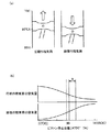
図3(a),(b)に示すように、圧縮行程気筒と膨張行程気筒とでは、それぞれ位相が180°CAだけずれているため、各ピストン13が互いに逆方向に作動する。膨張行程気筒のピストン13が行程中央よりも下死点側に位置していれば、その気筒の空気量が多くなって充分な燃焼エネルギーが得られる。しかし、上記膨張行程気筒のピストン13が極端に下死点側に位置した状態となると、圧縮行程気筒内の空気量が少なくなり過ぎて、再始動時の初回燃焼でクランクシャフト3を逆転させるための燃焼エネルギーが充分に得られなくなる。
As shown in FIGS. 3A and 3B, the phases of the compression stroke cylinder and the expansion stroke cylinder are shifted by 180 ° CA, so that the
これに対して上記膨張行程気筒の行程中央、つまり圧縮上死点後のクランク角が90°CAとなる位置よりもやや下死点側の所定範囲R、例えば圧縮上死点後のクランク角が100°〜120°CAとなる範囲R内にピストン13を停止させることができれば、圧縮行程気筒内に所定量の空気が確保されて上記初回の燃焼によりクランクシャフト3を少しだけ逆転させ得る程度の燃焼エネルギーが得られることになる。しかも、膨張行程気筒内に多くの空気量を確保することにより、クランクシャフト3を正転させるための燃焼エネルギーを充分に発生させてエンジンを確実に再始動させることが可能となる(以下この範囲Rを適正停止範囲Rとする)。そこで、ピストン13を適正停止範囲R内に停止させるよう、ECU2によってスロットル弁23の開度を調節する等のエンジン自動停止制御が行われる。
On the other hand, a predetermined range R slightly lower than the position where the crank angle after the compression top dead center is 90 ° CA, for example, the crank angle after the compression top dead center, is the stroke center of the expansion stroke cylinder. If the
このエンジン自動停止制御については種々提案されており、特許文献1や特許文献2にも詳述されているので、ここでは簡潔に記す。所定の自動停止条件が成立すると、エンジンへの燃料供給が停止される。するとエンジン回転速度が次第に低下して行き、まもなく完全に停止する。エンジンへの燃料供給を停止する前後のタイミングから完全に停止するまで、スロットル弁23の開度やオルタネータ28の発電量等を制御することにより、最終的にピストン13が上記適正停止範囲Rに停止するように調整される。ここでは、ピストン13を適正停止範囲Rに停止させることに成功したことを前提に以下説明を続ける。
Various types of engine automatic stop control have been proposed and are described in detail in
図4は、エンジン自動再始動制御、およびバックアップ始動制御を含むタイムチャートであり、上段にはエンジン回転速度と、バックアップ始動制御におけるスタータ36の駆動制御に関するチャート、下段には各気筒の行程推移チャートを示す。
FIG. 4 is a time chart including automatic engine restart control and backup start control. The upper part is a chart relating to the engine speed and the drive control of the
なお、以下説明を簡潔にするため、エンジンが完全に停止している時点t1において、#1気筒12Aが圧縮行程、#2気筒12Bが膨張行程、#3気筒12Cが吸気行程、#4気筒12Dが排気行程にあるものとする。そして便宜上、#1気筒12Aを停止時圧縮行程気筒12A、#2気筒12Bを停止時膨張行程気筒12B、#3気筒12Cを停止時吸気行程気筒12C、#4気筒12Dを停止時排気行程気筒12Dと称する。
For the sake of brevity, at time t1 when the engine is completely stopped, # 1
エンジン回転速度の特性は、二点鎖線で示す特性72が、通常の自動再始動制御の場合、つまり逆転始動方式による始動が成功した場合の特性である。また実線で示す特性71が、逆転始動方式による始動を試みたものの、第2TDCを超えられず、バックアップ始動制御によって始動を行った場合の特性である。下段の各チャートは、特性71の場合のものである(「87」を除く)。 The engine rotation speed characteristic is a characteristic when the characteristic 72 shown by a two-dot chain line is in the case of normal automatic restart control, that is, when the start by the reverse rotation start method is successful. A characteristic 71 indicated by a solid line is a characteristic when the start by the reverse rotation start method is attempted but the second TDC cannot be exceeded and the start is performed by the backup start control. The lower charts are for the characteristic 71 (excluding “87”).
まず、通常の自動再始動制御の場合について説明する。時点t1で所定のエンジン再始動条件(アクセルオン、ブレーキオフ、エアコンオン、バッテリー電圧が低下などのうち、少なくとも1つがYESのときに成立)が成立すると、ECU2は、まずピストン13の停止位置に基づいて停止時圧縮行程気筒12Aおよび停止時膨張行程気筒12B内の空気量を求め、さらにその空気量に応じて適宜空燃比となるように各気筒への燃料噴射量を設定する。
First, the case of normal automatic restart control will be described. When a predetermined engine restart condition (established when at least one of YES is selected among accelerator on, brake off, air conditioner on, battery voltage drop, etc.) is established at time t1,
そして、まず停止時圧縮行程気筒12Aに対して1回目の燃料噴射81が行われる。この燃料噴射81は、理論空燃比ないしはそれよりリッチ空燃比となるようにすることが望ましい。そうすることにより、停止時圧縮行程気筒12A内の空気量が少ないときであっても、逆転のための燃焼エネルギーを充分得ることができる。
First, the
そして燃料噴射81から気化時間を考慮して設定した時間の経過後に、当該気筒に対して点火82が行われる。この燃焼によって、エンジン(クランクシャフト3)は逆回転する。すなわちエンジン回転速度が負の値となる。
After the time set in consideration of the vaporization time from the
点火82から一定時間内にクランク角センサ30,31からの信号により、ピストン13が動いた(逆転を始めた)ことを確認後、停止時膨張行程気筒12Bに燃料噴射を行う。当実施形態では、停止時膨張行程気筒12Bへの燃料噴射を83と84とに分割して行う。前段噴射83によって気化が促進される。また後段噴射84によって、ピストン13が上死点に接近したときの筒内圧が低減され、ピストン13をより上死点近くにまで上昇させることができる。なお、前段噴射83は、もっと早期、例えば燃料噴射81と略同時期、あるいはそれよりも早い時期(再始動条件成立以前)に行っても良い。
After confirming that the
その後、所定のディレー時間経過後に点火され(85)、燃焼が行われる。この点火85による停止時膨張行程気筒12Bでの燃焼により、エンジンは逆転から正転に転じる(時点t2)。
Thereafter, ignition is performed after a predetermined delay time has elapsed (85), and combustion is performed. By the combustion in the
点火82後、燃料気化時間を考慮に入れ、停止時圧縮行程気筒12Aに2回目の燃料噴射86が行われる。燃料噴射86の噴射量は、燃料噴射81の噴射量とを合計した噴射量に基づく全体の空燃比が可燃空燃比(下限は7〜8)よりも更にリッチ(例えば6程度)になるように設定される。この燃料噴射86の気化潜熱によって、停止時圧縮行程気筒12Aの圧縮上死点(第1TDC。時点t3)付近の圧縮圧力が低減するので、少ないエネルギー消費量で第1TDCを越えることができる。
After the
なお、この停止時圧縮行程気筒12Aへの燃料噴射86は、専ら筒内の圧縮圧力を低減させるためになされるものであって、これに対する点火、燃焼は行われない(可燃空燃比よりもリッチなので自着火も起こらない)。この不燃燃料は、その後、排気通路22の排気浄化装置37によって無害化され、排出される。
It should be noted that the
上記のように停止時圧縮行程気筒12Aでの燃料噴射86による燃焼が行われないので、停止時膨張行程気筒12Bでの最初の燃焼に続く次の燃焼は、停止時吸気行程気筒12Cでの最初の燃焼となる。停止時吸気行程気筒12Cのピストン13が圧縮上死点(第2TDC)を越えるためのエネルギーとして、停止時膨張行程気筒12Bにおける初回燃焼のエネルギーの一部が充てられる。停止時膨張行程気筒12Bにおける初回燃焼のエネルギーは、停止時圧縮行程気筒12Aが第1TDCを超えるためと停止時吸気行程気筒12Cが第2TDCを越えるためとの両方に供される。従って、円滑な始動のためには停止時吸気行程気筒12Cが第2TDCを越えるためのエネルギーが小さいことが望ましい。
Since the combustion by the
また、停止時吸気行程気筒12Cは、エンジン停止中にサージタンク21b内で滞留して高温になった空気を最初に吸気する気筒である。このため、その圧縮行程における筒内温度が高くなりがちである。そのため、第2TDC前の圧縮行程で自着火してしまう虞がある。このような自着火が起こると、その燃焼によって第2TDC前に停止時吸気行程気筒12Cのピストン13を下死点側に押し戻す逆トルクが発生する(温間ロック)。これはその分第2TDCを越えるためのエネルギーを多く消費するので望ましくない。
In addition, the stop-time intake stroke cylinder 12C is a cylinder that first takes in air that has accumulated in the
そこで、停止時吸気行程気筒12Cが第2TDCを越えるためのエネルギーを小さくするために、また自着火を起こさせないようにするために、停止時吸気行程気筒12Cへの燃料噴射87(特定燃料供給)が第1TDC後の圧縮行程において行われる。 Therefore, in order to reduce the energy required for the stop-time intake stroke cylinder 12C to exceed the second TDC and not to cause self-ignition, fuel injection 87 (specific fuel supply) to the stop-time intake stroke cylinder 12C. Is performed in the compression stroke after the first TDC.
燃料噴射87が行われると、その気化潜熱によって圧縮圧力が低減するので、第2TDCを越えるための必要エネルギーが低減する。すなわち第2TDCが超えやすくなる。その噴射時期は、エンジンの自動停止期間、吸気温度、エンジン水温等に基いて、圧縮行程内の適宜タイミングとなるように設定される。 When the fuel injection 87 is performed, the compression pressure is reduced by the latent heat of vaporization, so that the energy required to exceed the second TDC is reduced. That is, the second TDC is easily exceeded. The injection timing is set at an appropriate timing within the compression stroke based on the automatic engine stop period, the intake air temperature, the engine water temperature, and the like.
また、燃料噴射87の気化潜熱によって圧縮圧力が低減するので、第2TDC前の自着火が抑制され、温間ロックが効果的に防止される。 Further, since the compression pressure is reduced by the latent heat of vaporization of the fuel injection 87, self-ignition before the second TDC is suppressed, and warm lock is effectively prevented.
次に、バックアップ始動制御を行う場合(エンジン回転速度の特性71)について説明する。この場合、点火86を行うまでは上記の場合と同様である。しかし何らかの原因で第2TDCを超えられないような事態となった場合には、第1TDC(時点t3)での回転速度が大きく落ち込み、その後(時点t4以降で)2回目の逆転が起きる。当実施形態では、この第1TDCでの回転速度が所定値以下となったとき、バックアップ始動制御が必要と判定し、実行する。
Next, the case of performing backup start control (engine speed characteristic 71) will be described. In this case, the same process as described above is performed until the
バックアップ始動制御では、まず特定燃料供給87を禁止する。第1TDCという早いタイミングでバックアップ始動制御の要否判定を行っているので、それが可能となる。 In the backup start control, the specific fuel supply 87 is first prohibited. Since it is determined whether or not the backup start control is necessary at the early timing of the first TDC, this is possible.
そして電磁VVT50によって、停止時吸気行程気筒12Cでの吸気弁開弁期間(通常は期間95)を期間96まで、つまりスタータ36の駆動による再圧縮がなされるときの圧縮行程途中(再圧縮が始まる時点t7以降で、後述する燃料噴射89より前)まで遅角する。この遅角量は、エンジン温度(冷却水温度)が高いほど大きい値に設定される。こうすることにより、温間ロックの起こり易い高温時であっても、これを効果的に抑制することができる。
Then, by the
そして一旦落ち込んで逆転したエンジンの回転速度が、正転に転じるまで待機する(時点t7)。そしてこのタイミングを捉え、望ましくはエンジン回転速度が、正転側で0〜60rpm程度の範囲で、スタータ36からリングギヤ36bを介してクランクシャフト3に正転方向の駆動力が付与される(A1)。その強い駆動力によって、エンジンが正転方向に始動する。
And it waits until the rotational speed of the engine which fell once and reversely turned to normal rotation (time t7). Then, based on this timing, a driving force in the normal rotation direction is applied from the
ところで、スタータ36は、スタータ制御部46が駆動開始信号を出してから、実際にクランクシャフト3に駆動力を付与するまでに、時間遅れTbを要する。従って、図4の時点t7でクランクシャフト3がスタータ36から駆動力を受けるためには、スタータ制御部46は、それよりも遅れ時間Tbだけ早いタイミング、すなわち時点t6でスタータ36の駆動を開始する必要がある。
By the way, the
以下、駆動開始時点t6の算出方法について説明する。 Hereinafter, a method of calculating the drive start time t6 will be described.
駆動開始時点t6は、スタータ制御部46によって、次の式(1)で求められる。
The drive start time t6 is obtained by the following expression (1) by the
(t6)=(t5)+(Ta)−(Tb) ・・・(式1)
(式1)において、t5は、駆動開始時点t6を求めるための起算点であって、ピストンが行程の中間点(90°CA)を通過した時点である。ここで、時点t4,t7と起算点t5との関係について説明する。時点t4は、行程の境界であり、ピストン13の反転ポイント(2回目の逆転が始まる時点)である。また時点t7は、ピストン13が逆転から正転に転じる時点であり、やはりピストンの反転ポイント(再圧縮の開始時点)である。つまり時点t4〜時点t7は、ピストン13の減衰振動における1/2周期となっている。減衰振動には、振幅が変化しても周期の変化が小さいという性質がある。つまり、時点t4と時点t7との時間的中心点は、減衰振動の中心、つまり行程中間点である起算点t5となるのである。
(T6) = (t5) + (Ta) − (Tb) (Formula 1)
In (Expression 1), t5 is a starting point for obtaining the drive start time t6, and is the time when the piston passes the intermediate point (90 ° CA) of the stroke. Here, the relationship between the time points t4 and t7 and the starting point t5 will be described. The time point t4 is a stroke boundary and is a reversal point of the piston 13 (a time point when the second reversal starts) . The time point t7 is a time point when the
従って次の(式2)が成り立つ。また図4から明らかに(式3)が成り立つ。 Therefore, the following (Formula 2) is established. Further, (Equation 3) is clearly established from FIG.
(Ta)=(Ta’)=(減衰振動の1/4周期) ・・・(式2)
(t6)=(t5)+(Ta’)−(Tb) ・・・(式3)
(式2)と(式3)から、(式1)が導き出せる。
(Ta) = (Ta ′) = (¼ period of damped vibration) (Expression 2)
(T6) = (t5) + (Ta ′) − (Tb) (Formula 3)
(Expression 1) can be derived from (Expression 2) and (Expression 3).
時間Taは、時点t4から時点t5までの経過時間であるから、スタータ制御部46は、時点t5以降は時間Taを既知の値とすることができる。また遅れ時間Tbは、予め実験等によって求められている値に、バッテリ電圧等の補正要素を考慮することにより、やはり既知の値とすることができる。こうして、起算点t5を経過したところで、(式1)によって駆動開始時点t6が求められるのである。
Since the time Ta is an elapsed time from the time point t4 to the time point t5, the
こうして、時点t5を起算点とすることにより、駆動開始時点t6を容易且つ精度良く求めることができる。またそうすることにより、スタータにかかる負担を軽減し、その耐久性低下を抑制することができる。 Thus, by using the time point t5 as the starting point, the drive start time point t6 can be obtained easily and accurately. Moreover, by doing so, the burden concerning a starter can be reduced and the durability fall can be suppressed.
時点t7以降、エンジンは正転に転じる。停止時吸気行程気筒12Cでは、圧縮によって筒内圧が高められる。しかし、吸気弁の閉時期が遅角されていることと、燃料噴射89が行われることにより、効果的に温間ロックが抑制される。また充分な新気があること、燃料噴射87が省略されていることから、スモーク(黒煙)の発生が抑制される。
After the time t7, the engine starts rotating forward. In the stop-time intake stroke cylinder 12C, the in-cylinder pressure is increased by compression. However, warm lock is effectively suppressed by delaying the closing timing of the intake valve and performing the
図5〜6は、バックアップ始動制御を含む自動再始動制御の制御フローチャートである。このフローチャートがスタートし、エンジンが完全停止した後(ステップS1でYES)、エンジンの再始動要求があったら(ステップS3でYES)、まず停止時圧縮行程気筒12Aでの燃焼制御を行ってエンジンを一旦逆転させる(ステップS5)。その後停止時膨張行程気筒12Bでの燃焼制御を行う(ステップS6)。
5 to 6 are control flowcharts of automatic restart control including backup start control. After this flowchart is started and the engine is completely stopped (YES in step S1), when there is a request for restarting the engine (YES in step S3), first, combustion control is performed in the
次に第1TDCでのエンジン回転速度が所定値以下であるか否かが判定される(ステップS7)。ここでYESの場合、第2TDCを超えることが困難と判定され、バックアップ始動制御を開始する。すなわち、電磁VVT50で停止時吸気行程気筒12Cの吸気弁19の開弁期間を延長する(ステップS9)。次に、エンジンが逆回転しつつ、所定のクランク位置(上死点と下死点の中間位置)となったか否かが判定される(ステップS11)。ステップS11でYESとなった時点が、図4の起算点t5である。ここでスタータ36の駆動開始時点t6の算出が可能になるので、その駆動制御を開始する(ステップS13)。
Next, it is determined whether or not the engine rotation speed at the first TDC is equal to or less than a predetermined value (step S7). If YES here, it is determined that it is difficult to exceed the second TDC, and the backup start control is started. That is, the valve opening period of the
そしてエンジンが逆転から正転に転じ(ステップS15でYES)、エンジン温度(水温センサ33によって検出される水温で代用)が高いほど遅角された所定のクランク位置となったら(ステップS17でYES)、吸気弁19が閉弁される(ステップS19)。さらに所定のクランク位置となったら(ステップS21でYES)、停止時吸気行程気筒12Cに燃料が供給され(ステップS23)、点火される(ステップS25)。そして通常燃焼に移行する(ステップS27)。
Then, when the engine turns from reverse to forward (YES in step S15) and the engine temperature (substitute with the water temperature detected by the water temperature sensor 33) becomes higher, the predetermined crank position is retarded (YES in step S17). The
一方、ステップS7でNOの場合は、バックアップ始動制御に移行せず、通常の逆転始動方式での始動(燃焼始動)を継続(ステップS29)した後、通常制御に移行する(ステップS27)。 On the other hand, in the case of NO in step S7, the routine does not shift to the backup start control but continues the normal reverse start (combustion start) (step S29) and then shifts to the normal control (step S27).
以上、本発明の実施形態について説明したが、この実施形態は、本発明の要旨を逸脱しない範囲で適宜変更可能である。その変形例を以下に説明する。 As mentioned above, although embodiment of this invention was described, this embodiment can be suitably changed in the range which does not deviate from the summary of this invention. The modification will be described below.
(1)上記実施形態では、エンジン再始動時にエンジンをいったん逆転作動させてから正転作動させるものとされているが、最初から正転作動だけで再始動させるものであってもよい。ただし、エンジンをいったん逆転作動させると、停止時膨張行程気筒12Bの燃焼エネルギーが高まることから、より確実にエンジンを再始動させることができる。また本発明の効果を顕著に享受することができる。
(1) In the above embodiment, when the engine is restarted, the engine is once reversely operated and then forwardly operated. However, the engine may be restarted only by the forward rotation operation from the beginning. However, once the engine is reversely operated, the combustion energy of the
(2)上記実施形態では、可変バルブタイミング機構として電磁VVT50を採用しているが、必ずしも電磁VVT50でなくても良く、例えばカム位相をずらせるもの等であっても良い。但し電磁VVT50とした場合には、制御の自由度が格段に増大する。
(2) In the above embodiment, the
(3)上記実施形態では、説明の都合上、#1気筒12Aを停止時圧縮行程気筒、#2気筒12Bを停止時膨張行程気筒、#3気筒12Cを停止時吸気行程気筒、#4気筒12Dを停止時排気行程気筒であるとしたが、必ずしもそのようにする必要はなく、また自動停止する度に変動しても良い。但し着火順序は変動しないので、どの気筒が停止時膨張行程気筒であるかが決定すれば、他の気筒は一義的に決定する。
(3) In the above embodiment, for convenience of explanation, the # 1
(4)上記実施形態の、自動再始動制御の開始時点である、エンジン完全停止に至る過程、或いは制御は、いかなるものであっても良い。また、ピストン13の停止位置が適正停止範囲Rにないものに本発明を適用しても良い。
(4) In the above-described embodiment, any process or control to the complete engine stop, which is the starting point of the automatic restart control, may be used. Further, the present invention may be applied to a case where the stop position of the
(5)上記実施形態では、燃料噴射弁16について筒内噴射型のものを採用しているが、ポート噴射型の燃料噴射弁を採用する場合にも適用することができる。しかし筒内直噴型であるほうが、追加燃料噴射86の効果を顕著に享受することができる。
(5) In the above embodiment, the in-cylinder injection type is used as the
1 エンジン本体
2 ECU(再始動制御手段)
12A #1気筒(停止時圧縮行程気筒)
12B #2気筒(停止時膨張行程気筒)
12C #3気筒(停止時吸気行程気筒)
12D #4気筒(停止時排気行程気筒)
16 燃料噴射弁(燃料供給手段)
19 吸気弁
33 水温センサ(温度検出手段)
36 スタータ(スタータモータ)
50 電磁VVT(電磁式動弁機構、可変バルブタイミング機構)
1
12D # 4 cylinder (exhaust stroke cylinder when stopped)
16 Fuel injection valve (fuel supply means)
19 Intake valve 33 Water temperature sensor (temperature detection means)
36 Starter (Starter Motor)
50 Electromagnetic VVT (Electromagnetic valve mechanism, variable valve timing mechanism)
Claims (5)
エンジンに正転方向の駆動力を付与するスタータモータと、
吸気弁の少なくとも閉弁時期を遅角可能な可変バルブタイミング機構とを備え、
上記再始動制御手段は、上記自動再始動制御において、所定時期に上記スタータモータを駆動させるバックアップ始動制御を必要に応じて行うように構成され、
上記バックアップ始動制御は、始動後の第1圧縮上死点でその要否が判別されるものであって、エンジンの回転が第2圧縮上死点を越えられないと判別されたときに必要と判定され、
上記再始動制御手段は、上記バックアップ始動制御を行わないとき、エンジン停止時に吸気行程にある気筒の、最初の圧縮行程での特定燃料供給を実行し、
上記再始動制御手段は、上記バックアップ始動制御を行うとき、上記特定燃料供給を禁止するとともに、その後エンジンが逆転を始めると、上記スタータモータを、エンジンが逆転から正転に転じる付近のタイミングで駆動力付与がなされるように駆動し、上記特定燃料供給を禁止した気筒で上記スタータモータの駆動による再圧縮がなされるときに、その再圧縮の開始後の圧縮行程途中まで吸気弁の閉弁時期を遅角させ、該吸気弁の閉弁後の圧縮行程において該気筒に燃料を供給することを特徴とするエンジンの始動装置。 Restart control that performs automatic restart control that automatically restarts by causing combustion in the cylinder in the expansion stroke at least when the engine is stopped when a predetermined restart condition is satisfied in the engine that is temporarily stopped An engine starter equipped with means,
A starter motor that applies driving force in the forward direction to the engine;
A variable valve timing mechanism capable of retarding at least the closing timing of the intake valve,
The restart control means is configured to perform backup start control as needed to drive the starter motor at a predetermined time in the automatic restart control.
The backup start control, be those whose necessity in the first compression TDC after startup is determined, required when the rotation of the engine is determined to not exceed the second compression top dead center Is determined,
The restart control means executes the specific fuel supply in the first compression stroke of the cylinder in the intake stroke when the engine is stopped when the backup start control is not performed,
It said restart control means, when performing the backup start control, as well as prohibiting the specific fuel supply, when subsequently the engine starts to reverse, driving the starter motor, at a timing in the vicinity of the engine turns from the reverse rotation to the normal rotation When re-compression is performed by driving the starter motor in a cylinder that is driven so that force is applied and the specified fuel supply is prohibited, the closing timing of the intake valve until the middle of the compression stroke after the start of re-compression An engine starter characterized in that fuel is supplied to the cylinder in a compression stroke after the intake valve is closed.
上記可変バルブタイミング機構は電磁力で開閉駆動する電磁式動弁機構であって、
上記吸気弁の閉弁時期遅角量は、エンジン温度が高いほど大きくなるように設定されることを特徴とする請求項1乃至3の何れか1項に記載のエンジンの始動装置。 Engine temperature detecting means for detecting the temperature state of the engine,
The variable valve timing mechanism is an electromagnetic valve mechanism that opens and closes by electromagnetic force,
4. The engine starter according to claim 1, wherein the valve closing timing retardation amount of the intake valve is set to increase as the engine temperature increases. 5.
5. The engine starter according to claim 4, wherein the fuel supply timing after the intake valve is closed is retarded in accordance with an increase width of the intake valve closing timing retardation amount.
Priority Applications (1)
| Application Number | Priority Date | Filing Date | Title |
|---|---|---|---|
| JP2006100945A JP4670710B2 (en) | 2006-03-31 | 2006-03-31 | Engine starter |
Applications Claiming Priority (1)
| Application Number | Priority Date | Filing Date | Title |
|---|---|---|---|
| JP2006100945A JP4670710B2 (en) | 2006-03-31 | 2006-03-31 | Engine starter |
Publications (2)
| Publication Number | Publication Date |
|---|---|
| JP2007270793A JP2007270793A (en) | 2007-10-18 |
| JP4670710B2 true JP4670710B2 (en) | 2011-04-13 |
Family
ID=38673841
Family Applications (1)
| Application Number | Title | Priority Date | Filing Date |
|---|---|---|---|
| JP2006100945A Expired - Fee Related JP4670710B2 (en) | 2006-03-31 | 2006-03-31 | Engine starter |
Country Status (1)
| Country | Link |
|---|---|
| JP (1) | JP4670710B2 (en) |
Families Citing this family (7)
| Publication number | Priority date | Publication date | Assignee | Title |
|---|---|---|---|---|
| JP5257002B2 (en) * | 2008-11-04 | 2013-08-07 | 日産自動車株式会社 | Engine restart control device and restart control method |
| CN102477877B (en) * | 2010-11-24 | 2014-04-02 | 南京理工大学 | Efficient and quick starting method of engine applying solenoid-driven valves |
| WO2013021812A1 (en) * | 2011-08-10 | 2013-02-14 | 三菱電機株式会社 | Engine starting device and engine starting method |
| JP5566530B2 (en) * | 2011-08-30 | 2014-08-06 | 三菱電機株式会社 | Engine starting device and engine starting method |
| DE102013212168B4 (en) * | 2013-06-26 | 2022-02-03 | Robert Bosch Gmbh | Method for starting an internal combustion engine, device, computer program product |
| JP6350058B2 (en) * | 2014-07-17 | 2018-07-04 | スズキ株式会社 | Motor control device |
| CN106762319B (en) * | 2016-12-29 | 2018-10-02 | 清华大学 | Four stroke aviation piston engine cold start strategies |
Citations (5)
| Publication number | Priority date | Publication date | Assignee | Title |
|---|---|---|---|---|
| JP2002039038A (en) * | 2000-07-27 | 2002-02-06 | Hitachi Ltd | Engine start device |
| JP2004301079A (en) * | 2003-03-31 | 2004-10-28 | Mazda Motor Corp | Engine starter |
| JP2005113781A (en) * | 2003-10-07 | 2005-04-28 | Nissan Motor Co Ltd | Engine starter |
| JP2005180208A (en) * | 2003-12-16 | 2005-07-07 | Mazda Motor Corp | Engine starter |
| JP2005315197A (en) * | 2004-04-30 | 2005-11-10 | Mazda Motor Corp | Engine starter |
-
2006
- 2006-03-31 JP JP2006100945A patent/JP4670710B2/en not_active Expired - Fee Related
Patent Citations (5)
| Publication number | Priority date | Publication date | Assignee | Title |
|---|---|---|---|---|
| JP2002039038A (en) * | 2000-07-27 | 2002-02-06 | Hitachi Ltd | Engine start device |
| JP2004301079A (en) * | 2003-03-31 | 2004-10-28 | Mazda Motor Corp | Engine starter |
| JP2005113781A (en) * | 2003-10-07 | 2005-04-28 | Nissan Motor Co Ltd | Engine starter |
| JP2005180208A (en) * | 2003-12-16 | 2005-07-07 | Mazda Motor Corp | Engine starter |
| JP2005315197A (en) * | 2004-04-30 | 2005-11-10 | Mazda Motor Corp | Engine starter |
Also Published As
| Publication number | Publication date |
|---|---|
| JP2007270793A (en) | 2007-10-18 |
Similar Documents
| Publication | Publication Date | Title |
|---|---|---|
| US7287500B2 (en) | Start controller for internal combustion engine | |
| JP4670710B2 (en) | Engine starter | |
| JP3743414B2 (en) | Engine starter | |
| JP4665818B2 (en) | Engine starter | |
| JP3841058B2 (en) | Engine starter | |
| JP3852389B2 (en) | Engine starter | |
| JP4135643B2 (en) | Control device for direct-injection spark-ignition internal combustion engine | |
| JP3966204B2 (en) | Engine starter | |
| JP5168065B2 (en) | Diesel engine control device and diesel engine control method | |
| JP2007270767A (en) | Engine starter | |
| JP2005030236A (en) | Control device of vehicle | |
| JP4075666B2 (en) | Engine starter | |
| JP4254607B2 (en) | Engine starter | |
| JP2004301078A (en) | Engine starter | |
| JP4569509B2 (en) | Engine starter | |
| JP2009222002A (en) | Automatic stop device for diesel engine | |
| JP4329589B2 (en) | Engine starter | |
| JP4683304B2 (en) | Engine stop control device | |
| JP2007092719A (en) | Starter of multicylinder engine | |
| JP4341477B2 (en) | Engine starter | |
| JP2007270768A (en) | Engine starter | |
| JP4206847B2 (en) | Vehicle control device | |
| JP2007092720A (en) | Starter of multicylinder engine | |
| JP4325477B2 (en) | Engine starter | |
| JP4103664B2 (en) | Engine starter |
Legal Events
| Date | Code | Title | Description |
|---|---|---|---|
| A621 | Written request for application examination |
Free format text: JAPANESE INTERMEDIATE CODE: A621 Effective date: 20090123 |
|
| A977 | Report on retrieval |
Free format text: JAPANESE INTERMEDIATE CODE: A971007 Effective date: 20100927 |
|
| A131 | Notification of reasons for refusal |
Free format text: JAPANESE INTERMEDIATE CODE: A131 Effective date: 20101005 |
|
| A521 | Written amendment |
Free format text: JAPANESE INTERMEDIATE CODE: A523 Effective date: 20101201 |
|
| TRDD | Decision of grant or rejection written | ||
| A01 | Written decision to grant a patent or to grant a registration (utility model) |
Free format text: JAPANESE INTERMEDIATE CODE: A01 Effective date: 20101221 |
|
| A01 | Written decision to grant a patent or to grant a registration (utility model) |
Free format text: JAPANESE INTERMEDIATE CODE: A01 |
|
| A61 | First payment of annual fees (during grant procedure) |
Free format text: JAPANESE INTERMEDIATE CODE: A61 Effective date: 20110103 |
|
| R150 | Certificate of patent or registration of utility model |
Ref document number: 4670710 Country of ref document: JP Free format text: JAPANESE INTERMEDIATE CODE: R150 Free format text: JAPANESE INTERMEDIATE CODE: R150 |
|
| FPAY | Renewal fee payment (event date is renewal date of database) |
Free format text: PAYMENT UNTIL: 20140128 Year of fee payment: 3 |
|
| LAPS | Cancellation because of no payment of annual fees |