JP4667269B2 - Wide-angle lens system - Google Patents
Wide-angle lens system Download PDFInfo
- Publication number
- JP4667269B2 JP4667269B2 JP2006047922A JP2006047922A JP4667269B2 JP 4667269 B2 JP4667269 B2 JP 4667269B2 JP 2006047922 A JP2006047922 A JP 2006047922A JP 2006047922 A JP2006047922 A JP 2006047922A JP 4667269 B2 JP4667269 B2 JP 4667269B2
- Authority
- JP
- Japan
- Prior art keywords
- lens
- positive
- group
- wide
- object side
- Prior art date
- Legal status (The legal status is an assumption and is not a legal conclusion. Google has not performed a legal analysis and makes no representation as to the accuracy of the status listed.)
- Active
Links
- 230000014509 gene expression Effects 0.000 claims description 33
- 230000004075 alteration Effects 0.000 description 41
- 238000010586 diagram Methods 0.000 description 27
- 230000005499 meniscus Effects 0.000 description 14
- 201000009310 astigmatism Diseases 0.000 description 6
- 206010010071 Coma Diseases 0.000 description 4
- 239000000463 material Substances 0.000 description 3
- 239000011521 glass Substances 0.000 description 2
- 230000011514 reflex Effects 0.000 description 2
- 230000003287 optical effect Effects 0.000 description 1
- 229920003002 synthetic resin Polymers 0.000 description 1
- 239000000057 synthetic resin Substances 0.000 description 1
Images


Classifications
-
- G—PHYSICS
- G02—OPTICS
- G02B—OPTICAL ELEMENTS, SYSTEMS OR APPARATUS
- G02B13/00—Optical objectives specially designed for the purposes specified below
- G02B13/06—Panoramic objectives; So-called "sky lenses" including panoramic objectives having reflecting surfaces
-
- G—PHYSICS
- G02—OPTICS
- G02B—OPTICAL ELEMENTS, SYSTEMS OR APPARATUS
- G02B9/00—Optical objectives characterised both by the number of the components and their arrangements according to their sign, i.e. + or -
- G02B9/04—Optical objectives characterised both by the number of the components and their arrangements according to their sign, i.e. + or - having two components only
Landscapes
- Physics & Mathematics (AREA)
- General Physics & Mathematics (AREA)
- Optics & Photonics (AREA)
- Lenses (AREA)
Description
本発明は、デジタル一眼レフ(SLR)カメラ用として好適な広角レンズ系に関する。 The present invention relates to a wide-angle lens system suitable for a digital single lens reflex (SLR) camera.
焦点距離に対して比較的長いバックフォーカスを必要とする一眼レフカメラ用の広角レンズ系としては、物体側から負正の配置のレトロフォーカス型が広く用いられており、そのパワー配置、レンズ構成、寸法構成等について各種の提案がなされている。
本発明は、レトロフォーカス型の広角レンズ系であって、より薄型(小型)で諸収差、特にコマ収差、歪曲収差、色収差が良好に補正された画角が70゜程度の高性能な広角レンズ系を得ることを目的とする。 The present invention is a retrofocus-type wide-angle lens system, which is thinner and more compact and has a high-performance wide-angle lens with a field angle of about 70 ° in which various aberrations, in particular coma, distortion, and chromatic aberration are well corrected. The goal is to obtain a system.
本発明の広角ズームレンズ系は、物体側から順に、負の前群と正の後群からなる広角レンズ系において、前群は、物体側から順に、正負レンズ各1枚からなる負の第1aレンズ群と正負レンズ各1枚からなる正の第1bレンズ群からなり、後群は、物体側から順に、正レンズと負レンズの貼合せレンズ、像側に凸面を向けた正レンズ、及び正レンズからなり、次の条件式(1)、(2)及び(4)を満足することを特徴としている。
(1)-0.8<f1a/f1b<-0.1
(2)0.6<f/fR<1.1
(4)νd1-7>70
但し、
f1a;第1aレンズ群の焦点距離、
f1b;第1bレンズ群の焦点距離、
f;全系の焦点距離、
fR;後群の焦点距離、
νd1-7;後群中の像側に凸面を向けた正レンズのアッベ数、
である。
The wide-angle zoom lens system according to the present invention is a wide-angle lens system including a negative front group and a positive rear group in order from the object side , and the front group is a negative first lens including one positive and negative lens in order from the object side. The lens group and a positive first-b lens group each consisting of one positive and negative lens, and the rear group in order from the object side, a cemented lens of a positive lens and a negative lens, a positive lens with a convex surface facing the image side, and a positive lens It consists of a lens and satisfies the following conditional expressions (1), (2) and (4) .
(1) -0.8 <f1a / f1b <-0.1
(2) 0.6 <f / fR <1.1
(4) νd1-7> 70
However,
f1a: focal length of the 1a lens group,
f1b; focal length of the 1b lens group,
f: focal length of the entire system,
fR: focal length of rear group,
νd1-7; Abbe number of positive lens with convex surface facing the image side in the rear group,
It is.
本発明の広角レンズ系は、次の条件式(3)を満足することが好ましい。
(3)-0.7<fR/fF<-0.1
但し、
fF;前群の焦点距離、
である。
The wide-angle lens system of the present invention preferably satisfies the following conditional expression (3).
(3) -0.7 <fR / fF <-0.1
However,
fF: Focal length of the front group,
It is.
第1aレンズ群の正負レンズの順は、物体側から正レンズと負レンズとし、第1bレンズ群の正負レンズの順は、物体側から順に負レンズと正レンズとするのが好ましい。The order of the positive and negative lenses in the 1a lens group is preferably a positive lens and a negative lens from the object side, and the order of positive and negative lenses in the 1b lens group is preferably a negative lens and a positive lens in order from the object side.
さらに具体的には例えば、第1aレンズ群は、物体側から順に、物体側に凸面を向けた正の第1レンズと負の第2レンズから構成し、第1bレンズ群は、物体側に凸面を向けた負の第3レンズと正の第4レンズから構成することができる。
More specifically, for example, the 1a lens group includes, in order from the object side, a positive first lens having a convex surface facing the object side and a negative second lens, and the 1b lens group has a convex surface facing the object side. And a negative third lens and a positive fourth lens.
本発明の広角レンズ系は、次の条件式(5)を満足することが望ましい。
(5)0.1<d/f<0.35
但し、
d;前群と後群の軸上空気間隔、
である。
The wide-angle lens system of the present invention preferably satisfies the following conditional expression (5).
(5) 0.1 <d / f <0.35
However,
d; axial air space between the front group and the rear group,
It is.
絞は、前群と後群の間に配置するのがよい。 The diaphragm is preferably arranged between the front group and the rear group.
本発明によれば、レトロフォーカス型の広角レンズ系であって、従来品とは異なる条件を満足することにより、より薄型(小型)で諸収差、特にコマ収差、歪曲収差、色収差が良好に補正された画角が70゜程度の高性能な広角レンズ系を得ることができる。 According to the present invention, it is a retrofocus type wide-angle lens system, and various aberrations, in particular coma aberration, distortion aberration, and chromatic aberration, can be satisfactorily corrected by satisfying conditions different from those of conventional products. A high-performance wide-angle lens system with an angle of view of about 70 ° can be obtained.
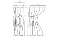
本実施形態の広角レンズ系は、図1、図3、図5、図7、図9及び図11の各実施例に示すように、物体側から順に、絞りSで分けられる負の前群10と正の後群20を有している。前群10は、物体側から順に、負の第1aレンズ群11と正の第1bレンズ群12からなっている。前群10は、全ての実施例で4枚構成であり、第1aレンズ群と第1bレンズ群はそれぞれ、正負レンズ各1枚からなっている。また、全ての実施例において、第1aレンズ群11は、物体側から順に、物体側に凸面を向けた正の第1レンズと負の第2レンズからなり、第1bレンズ群12は、物体側から順に、物体側に凸面を向けた負の第3レンズと正の第4レンズからなっている。また、後群20は、物体側から順に、正の第5レンズと負の第6レンズの貼合せレンズ、像側に凸面を向けた正の第7レンズ、及び正の第8レンズからなっている。第5レンズと第6レンズの合成パワーは負である。
The wide-angle lens system of the present embodiment includes a
レトロフォーカス型のレンズは一般に、全系の焦点距離よりも長いバックフォーカスを得るもので、そのために絞りSに対して非対称なパワー配置をとっている。そのため、必要とするバックフォーカスを確保したままレンズ系を短くしようとすると、歪曲収差、非点収差、球面収差等の諸収差の補正が困難である。負のパワーの前群は、該前群での歪曲収差の発生を抑えるために、少なくとも1枚の正レンズを含む複数のレンズから構成されている。前群は全体としては負のパワーを与えるので、少なくとも1枚の負レンズが含まれており、このため、非点収差、歪曲収差、色収差の補正が可能である。また、絞りSの物体側近傍に比較的厚い正レンズを配置することにより歪曲収差を良好に補正している。 In general, a retrofocus type lens obtains a back focus longer than the focal length of the entire system, and therefore, an asymmetrical power arrangement with respect to the stop S is adopted. Therefore, it is difficult to correct various aberrations such as distortion, astigmatism, and spherical aberration when attempting to shorten the lens system while ensuring the required back focus. The front group having a negative power includes a plurality of lenses including at least one positive lens in order to suppress the occurrence of distortion in the front group. Since the front group gives negative power as a whole, it includes at least one negative lens, and astigmatism, distortion, and chromatic aberration can be corrected. In addition, by arranging a relatively thick positive lens in the vicinity of the object side of the diaphragm S, the distortion is corrected well.
正のパワーの後群に関しては、軸外収差に与える影響を小さく保ったまま全系で発生する球面収差を補正するために、負の球面収差を発生させる少なくとも1枚の負レンズを含ませている。そして、球面収差やコマ収差の発生を抑えるために、少なくとも3枚の正レンズを含ませている。また、負レンズの両側に正レンズを位置させ、絞に近い正レンズと負レンズを貼り合わせることにより、高次の球面収差を良好に補正している。
For the rear group of positive power, at least one negative lens that generates negative spherical aberration is included in order to correct spherical aberration generated in the entire system while keeping the influence on off-axis aberration small. Yes. In order to suppress the occurrence of spherical aberration and coma, at least three positive lenses are included. In addition, the positive lens is positioned on both sides of the negative lens, and the positive lens close to the stop and the negative lens are bonded together, so that high-order spherical aberration is corrected well.
条件式(1)は、前群10の第1aレンズ群11と第1bレンズ群12のパワー配置に関する条件式であり、特に像面湾曲を補正するための条件である。条件式(1)の上限を超えると、像面湾曲がアンダーとなり、下限を超えるとオーバーになる。この条件式(1)の下限値を-0.6とする((1’)-0.6<f1a/f1b<-0.1)と、さらに良好な像面湾曲の補正が可能となる。
Conditional expression (1) is a conditional expression regarding the power arrangement of the 1a
条件式(2)は、正の後群のパワーに関する条件式である。条件式(2)の上限を超えて後群の正のパワーが強くなると、球面収差の補正が困難になる。条件式(2)の下限を超えて後群の正のパワーが弱くなると、非点収差が悪化し、補正が困難になる。この条件式(2)の下限を0.7とする((2’)0.7<f/fR<1.1)と、より良好な収差補正が可能となる。
Conditional expression (2) is a conditional expression regarding the power of the positive rear group. When the upper limit of conditional expression (2) is exceeded and the positive power of the rear group becomes strong, correction of spherical aberration becomes difficult. If the lower limit of conditional expression (2) is exceeded and the positive power of the rear group becomes weak, astigmatism deteriorates and correction becomes difficult. When the lower limit of the conditional expression (2) is set to 0.7 ((2 ′) 0.7 <f / fR <1.1), better aberration correction can be performed.
条件式(3)は、前群と後群のパワーバランスに関する条件である。条件式(3)の上限を超えて後群の正のパワーが強くなると、前玉径が増大し、球面収差が悪化し、バックフォーカスが不足する。条件式(3)の下限を超えて前群の負のパワーが強くなると、像面湾曲、非点収差が悪化し、補正が困難になる。この条件式(3)の上限を-0.3とする((3’)-0.7<fR/fF<-0.3)ことによって、さらに良好な収差補正が可能になる。 Conditional expression (3) is a condition relating to the power balance between the front group and the rear group. If the upper power of conditional expression (3) is exceeded and the positive power of the rear group increases, the front lens diameter increases, spherical aberration deteriorates, and the back focus is insufficient. If the negative power of the front group increases beyond the lower limit of conditional expression (3), field curvature and astigmatism will deteriorate and correction will be difficult. By setting the upper limit of the conditional expression (3) to −0.3 ((3 ′) − 0.7 <fR / fF <−0.3), further excellent aberration correction can be performed.
条件式(4)は、正の第7レンズの硝材のアッベ数に関する条件式である。条件式(4)の下限を超えるアッベ数を持つ硝材を使用すると、軸上色収差と倍率色収差の補正が困難となる。
Conditional expression (4) is a conditional expression related to the Abbe number of the glass material of the positive seventh lens. If a glass material having an Abbe number exceeding the lower limit of the conditional expression (4) is used, it is difficult to correct axial chromatic aberration and lateral chromatic aberration.
条件式(5)は、前群と後群の間隔に関する条件式である。条件式(5)の上限を超えるとレンズ系の全長が長くなり小型化が困難になる。また、条件式(5)の下限を超えると、像面湾曲や非点収差の補正が困難になる。 Conditional expression (5) is a conditional expression regarding the interval between the front group and the rear group. If the upper limit of conditional expression (5) is exceeded, the total length of the lens system becomes long and it becomes difficult to reduce the size. If the lower limit of conditional expression (5) is exceeded, it will be difficult to correct field curvature and astigmatism.
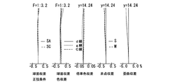
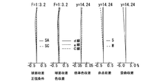
次に具体的な実施例を示す。諸収差図及び表中、SAは球面収差、SCは正弦条件、球面収差で表される色収差(軸上色収差)図及び倍率色収差図中のd線、g線、C線はそれぞれの波長に対する収差、Sはサジタル、Mはメリディオナル、Wは半画角(゜)、FはFナンバー、fは全系の焦点距離、fBはバックフォーカス、yは最大像高、rは曲率半径、dはレンズ厚またはレンズ間隔、Nd はd線の屈折率、νはアッベ数を示す。
また、回転対称非球面は次式で定義される。
x=cy2/[1+[1-(1+K)c2y2]1/2]+A4y4+A6y6+A8y8+A10y10+A12y12・・・
(但し、cは曲率(1/r)、yは光軸からの高さ、Kは円錐係数、A4、A6、A8、・・・・・は各次数の非球面係数)
Next, specific examples will be described. In the various aberration diagrams and tables, SA is spherical aberration, SC is a sine condition, chromatic aberration (axial chromatic aberration) diagram represented by spherical aberration, and d-line, g-line, and C-line are chromatic aberrations for each wavelength. , S is sagittal, M is meridional, W is half angle of view (°), F is F number, f is focal length of whole system, fB is back focus, y is maximum image height, r is radius of curvature, d is lens Thickness or lens interval, N d is the refractive index of the d-line, and ν is the Abbe number.
A rotationally symmetric aspherical surface is defined by the following equation.
x = cy 2 / [1+ [1- (1 + K) c 2 y 2 ] 1/2 ] + A4y 4 + A6y 6 + A8y 8 + A10y 10 + A12y 12 ...
(Where c is the curvature (1 / r), y is the height from the optical axis, K is the conic coefficient, A4, A6, A8,... Are the aspheric coefficients of each order)
図1及び図2と表1は本発明による広角レンズの実施例1を示している。図1はレンズ構成図、図2はその諸収差図、表1はその無限遠撮影状態における数値データである。
本実施例の広角レンズは、物体側から順に、負の前群10、絞りS、及び正の後群20からなる。前群10は、物体側から順に、負の第1aレンズ群11、正の第1bレンズ群12からなる。第1aレンズ群11は、物体側から順に、物体側に凸の正メニスカスレンズと物体側に凸の負メニスカスレンズからなる。第1bレンズ群12は、物体側から順に、物体側に凸の負メニスカスレンズと両凸正レンズからなる。後群20は、物体側から順に、両凸レンズと両凹レンズとの接合レンズ、像側に凸の正メニスカスレンズ、及び像側に凸の正メニスカスレンズからなる。絞りSは、第8面(第1bレンズ群12)の極から後方2.79にある。
(表1)
F = 1: 3.3
f = 20.60
W = 35.2
fB = 37.80
面 No. r d Nd ν
1 34.251 2.51 1.58667 55.1
2 176.873 0.10 ‐ ‐
3 16.734 1.20 1.80015 47.0
4 7.655 3.37 ‐ ‐
5 34.173 1.20 1.80400 46.6
6 10.493 3.56 ‐ ‐
7 16.332 3.24 1.79614 25.4
8 -117.039 4.28 ‐ ‐
9 345.109 2.92 1.54026 46.4
10 -10.178 1.00 1.80699 28.7
11 36.388 0.82 ‐ ‐
12 -130.278 2.79 1.49700 81.6
13 -10.689 0.10 ‐ ‐
14 -236.485 2.11 1.71345 54.5
15 -20.380 - ‐ ‐
1 and 2 and Table 1 show Example 1 of a wide-angle lens according to the present invention. FIG. 1 is a lens configuration diagram, FIG. 2 is a diagram showing various aberrations thereof, and Table 1 is numerical data in an infinite photographing state.
The wide-angle lens of this embodiment includes a
(Table 1)
F = 1: 3.3
f = 20.60
W = 35.2
fB = 37.80
Surface No. r d N d ν
1 34.251 2.51 1.58667 55.1
2 176.873 0.10--
3 16.734 1.20 1.80015 47.0
4 7.655 3.37--
5 34.173 1.20 1.80 400 46.6
6 10.493 3.56--
7 16.332 3.24 1.79614 25.4
8 -117.039 4.28--
9 345.109 2.92 1.54026 46.4
10 -10.178 1.00 1.80699 28.7
11 36.388 0.82--
12 -130.278 2.79 1.49700 81.6
13 -10.689 0.10--
14 -236.485 2.11 1.71345 54.5
15 -20.380---
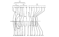
図3及び図4と表2は本発明による広角レンズの実施例2を示している。図3はレンズ構成図、図4はその諸収差図、表2はその無限遠撮影状態における数値データである。基本的なレンズ構成は、実施例1と同様である。絞りSは、第8面(第1bレンズ群12)の極から後方2.59にある。
(表2)
F = 1:3.3
f = 20.60
W = 35.2
fB = 37.80
面 No. r d Nd ν
1 27.251 2.76 1.58640 48.4
2 97.504 0.10 ‐ ‐
3 15.993 1.20 1.77000 49.0
4 7.599 3.54 ‐ ‐
5 37.038 1.20 1.80400 46.6
6 9.052 3.04 ‐ ‐
7 15.781 4.25 1.75692 26.8
8 -64.512 3.58 ‐ ‐
9 172.756 2.51 1.54001 46.4
10 -11.089 1.00 1.80700 28.0
11 34.342 0.87 ‐ ‐
12 -105.548 2.82 1.48749 70.2
13 -10.386 0.10 ‐ ‐
14 -167.462 2.21 1.65000 57.2
15 -18.013 - - -
3 and 4 and Table 2 show Example 2 of the wide-angle lens according to the present invention. FIG. 3 is a lens configuration diagram, FIG. 4 is a diagram of various aberrations thereof, and Table 2 is numerical data in an infinite photographing state. The basic lens configuration is the same as that of the first embodiment. The stop S is 2.59 behind the pole of the eighth surface (the 1b lens group 12).
(Table 2)
F = 1: 3.3
f = 20.60
W = 35.2
fB = 37.80
Surface No. r d N d ν
1 27.251 2.76 1.58640 48.4
2 97.504 0.10--
3 15.993 1.20 1.77000 49.0
4 7.599 3.54--
5 37.038 1.20 1.80 400 46.6
6 9.052 3.04--
7 15.781 4.25 1.75692 26.8
8 -64.512 3.58--
9 172.756 2.51 1.54001 46.4
10 -11.089 1.00 1.80 700 28.0
11 34.342 0.87--
12 -105.548 2.82 1.48749 70.2
13 -10.386 0.10--
14 -167.462 2.21 1.65000 57.2
15 -18.013---
図5及び図6と表3は本発明による広角レンズの実施例3を示している。図5はレンズ構成図、図6はその諸収差図、表3はその無限遠撮影状態における数値データである。後群20は、物体側から順に、両凸レンズと両凹レンズとの接合レンズ、両凸レンズ、及び像側に凸の正メニスカスレンズからなる。その他の基本構成は実施例1と同様である。絞りSは、第8面(第1bレンズ群12)の極から後方1.55にある。
(表3)
F = 1: 3.3
f = 20.60
W = 35.3
fB = 37.80
面 No. r d Nd ν
1 29.999 2.43 1.66672 48.3
2 83.360 0.10 ‐ ‐
3 17.736 1.20 1.77250 49.6
4 8.210 3.30 ‐ ‐
5 32.129 1.20 1.77250 49.6
6 9.492 4.20 ‐ ‐
7 20.295 4.30 1.76182 26.5
8 -70.229 2.55 ‐ ‐
9 113.064 5.07 1.58313 59.4
10 -23.796 2.00 1.80518 25.4
11 28.503 0.81 ‐ ‐
12 460.778 2.72 1.48749 70.2
13 -12.264 0.10 ‐ ‐
14 -84.271 1.98 1.69680 55.5
15 -20.250 - ‐ ‐
5 and 6 and Table 3 show Example 3 of the wide-angle lens according to the present invention. FIG. 5 is a lens configuration diagram, FIG. 6 is a diagram of various aberrations thereof, and Table 3 is numerical data in an infinite distance photographing state. The
(Table 3)
F = 1: 3.3
f = 20.60
W = 35.3
fB = 37.80
Surface No. r d N d ν
1 29.999 2.43 1.66672 48.3
2 83.360 0.10 ‐ ‐
3 17.736 1.20 1.77250 49.6
4 8.210 3.30--
5 32.129 1.20 1.77250 49.6
6 9.492 4.20--
7 20.295 4.30 1.76182 26.5
8 -70.229 2.55--
9 113.064 5.07 1.58313 59.4
10 -23.796 2.00 1.80518 25.4
11 28.503 0.81--
12 460.778 2.72 1.48749 70.2
13 -12.264 0.10--
14 -84.271 1.98 1.69680 55.5
15 -20.250---
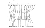
図7及び図8と表4は本発明による広角レンズの実施例4を示している。図7はレンズ構成図、図8はその諸収差図、表4はその無限遠撮影状態における数値データである。基本的なレンズ構成は実施例1と同様である。絞りSは、第8面(第1bレンズ群12)の極から後方1.70にある。
(表4)
F = 1: 3.3
f = 20.60
W = 35.4
fB = 37.80
面 No. r d Nd ν
1 35.085 2.36 1.66672 48.3
2 132.629 0.10 ‐ ‐
3 17.984 1.20 1.78800 47.4
4 7.824 4.57 ‐ ‐
5 46.388 1.20 1.78800 47.4
6 9.486 1.81 ‐ ‐
7 15.715 2.93 1.76182 26.5
8 -54.289 4.94 ‐ ‐
9 247.462 2.18 1.58313 59.4
10 -22.838 1.50 1.80518 25.4
11 34.590 0.82 ‐ ‐
12 -192.776 2.87 1.49700 81.6
13 -10.720 0.10 ‐ ‐
14 -74.221 1.94 1.69680 55.5
15 -20.527 - ‐ ‐
7 and 8 and Table 4 show Example 4 of the wide-angle lens according to the present invention. FIG. 7 is a lens configuration diagram, FIG. 8 is a diagram of various aberrations thereof, and Table 4 is numerical data in an infinite photographing state. The basic lens configuration is the same as that of the first embodiment. The stop S is 1.70 behind the pole of the eighth surface (the 1b lens group 12).
(Table 4)
F = 1: 3.3
f = 20.60
W = 35.4
fB = 37.80
Surface No. r d N d ν
1 35.085 2.36 1.66672 48.3
2 132.629 0.10--
3 17.984 1.20 1.78800 47.4
4 7.824 4.57--
5 46.388 1.20 1.78800 47.4
6 9.486 1.81--
7 15.715 2.93 1.76182 26.5
8 -54.289 4.94--
9 247.462 2.18 1.58313 59.4
10 -22.838 1.50 1.80518 25.4
11 34.590 0.82--
12 -192.776 2.87 1.49700 81.6
13 -10.720 0.10--
14 -74.221 1.94 1.69680 55.5
15 -20.527---
図9及び図10と表5は本発明による広角レンズの実施例5を示している。図9はレンズ構成図、図10はその諸収差図、表5はその無限遠撮影状態における数値データである。
第1aレンズ群11は、物体側から順に、物体側に凸の正メニスカスレンズ、物体側の面に合成樹脂材料による非球面層が接着形成された物体側に凸の負メニスカスレンズからなる。第1bレンズ群12は、物体側から順に、物体側に凸の負メニスカスレンズと物体側に凸の正メニスカスレンズからなる。後群20は、物体側から順に、像側に凸の正メニスカスレンズと両凹レンズとの接合レンズ、像側に凸の正メニスカスレンズ、及び像側に凸の正メニスカスレンズからなる。
絞りSは、第9面(第1bレンズ群12)の極から後方3.68にある。
(表5)
F = 1: 3.3
f = 21.60
W = 35.0
fB = 38.52
面 No. r d Nd ν
1 65.020 1.90 1.66672 48.3
2 393.172 0.10 ‐ ‐
3* 18.258 0.15 1.52972 42.7
4 16.938 1.10 1.80400 46.6
5 7.650 4.23 ‐ ‐
6 25.571 1.20 1.77250 49.6
7 10.183 1.42 ‐ ‐
8 14.055 3.28 1.80518 25.4
9 1551.792 4.93 ‐ ‐
10 -6615.794 2.32 1.53172 48.9
11 -17.530 1.50 1.80518 25.4
12 43.071 0.53 ‐ ‐
13 -255.095 2.97 1.49700 81.6
14 -11.269 0.10 ‐ ‐
15 -91.438 2.08 1.69680 55.5
16 -19.360 - ‐ ‐
*は回転対称非球面。
非球面データ(表示していない非球面係数は0.00である。);
面NO K A4 A6 A8
3 0.00 0.31989×10⁻⁴ -0.32959×10⁻⁷ 0.11620×10⁻⁸
9 and 10 and Table 5 show Example 5 of the wide-angle lens according to the present invention. FIG. 9 is a lens configuration diagram, FIG. 10 is a diagram of various aberrations thereof, and Table 5 is numerical data in an infinite state photographing state.
The first a
The stop S is 3.68 behind the pole of the ninth surface (the 1b lens group 12).
(Table 5)
F = 1: 3.3
f = 21.60
W = 35.0
fB = 38.52
Surface No. r d N d ν
1 65.020 1.90 1.66672 48.3
2 393.172 0.10--
3 * 18.258 0.15 1.52972 42.7
4 16.938 1.10 1.80 400 46.6
5 7.650 4.23--
6 25.571 1.20 1.77250 49.6
7 10.183 1.42--
8 14.055 3.28 1.80518 25.4
9 1551.792 4.93--
10 -6615.794 2.32 1.53172 48.9
11 -17.530 1.50 1.80518 25.4
12 43.071 0.53--
13 -255.095 2.97 1.49700 81.6
14 -11.269 0.10--
15 -91.438 2.08 1.69680 55.5
16 -19.360---
* Is a rotationally symmetric aspherical surface.
Aspheric data (Aspheric coefficient not shown is 0.00);
Surface NO K A4 A6 A8
3 0.00 0.31989 × 10 -4 -0.32959 × 10 -7 0.11620 × 10 -8
図11及び図12と表6は本発明による広角レンズの実施例6を示している。図11はレンズ構成図、図12はその諸収差図、表6はその無限遠撮影状態における数値データである。
第1bレンズ群12は、物体側から順に、物体側に凸の負メニスカスレンズと両凸レンズからなる。その他の基本的なレンズ構成は実施例5と同様である。絞りSは、第9面(第1bレンズ群12)の極から後方3.66にある。
(表6)
F = 1: 3.3
f = 21.60
W = 35.0
fB = 37.82
面 No. r d Nd ν
1 99.992 1.68 1.66672 48.3
2 730.173 0.08 ‐ ‐
3* 17.237 0.07 1.52972 42.7
4 15.816 1.10 1.80400 46.6
5 7.900 3.59 ‐ ‐
6 23.598 1.20 1.77250 49.6
7 11.205 2.57 ‐ ‐
8 17.162 3.81 1.80518 25.4
9 -195.142 4.94 ‐ ‐
10 -182.306 2.35 1.53172 48.9
11 -18.295 1.40 1.80518 25.4
12 37.438 0.52 ‐ ‐
13 -580.401 2.85 1.49700 81.6
14 -12.889 0.10 ‐ ‐
15 -95.846 2.24 1.69680 55.5
16 -17.479 - ‐ ‐
*は回転対称非球面。
非球面データ(表示していない非球面係数は0.00である。);
面NO K A4 A6 A8
3 0.00 0.33350×10⁻⁴ 0.52093×10⁻⁹ 0.17459×10⁻⁸
11 and 12 and Table 6 show Example 6 of the wide-angle lens according to the present invention. FIG. 11 is a lens configuration diagram, FIG. 12 is a diagram showing various aberrations thereof, and Table 6 is numerical data in the infinity photographing state.
The 1b lens group 12 includes a negative meniscus lens and a biconvex lens that are convex toward the object side in order from the object side. Other basic lens configurations are the same as those in the fifth embodiment. The stop S is located 3.66 behind the pole of the ninth surface (the 1b lens group 12).
(Table 6)
F = 1: 3.3
f = 21.60
W = 35.0
fB = 37.82
Surface No. r d N d ν
1 99.992 1.68 1.66672 48.3
2 730.173 0.08--
3 * 17.237 0.07 1.52972 42.7
4 15.816 1.10 1.80 400 46.6
5 7.900 3.59--
6 23.598 1.20 1.77250 49.6
7 11.205 2.57--
8 17.162 3.81 1.80518 25.4
9 -195.142 4.94--
10 -182.306 2.35 1.53172 48.9
11 -18.295 1.40 1.80518 25.4
12 37.438 0.52--
13 -580.401 2.85 1.49700 81.6
14 -12.889 0.10--
15 -95.846 2.24 1.69680 55.5
16 -17.479---
* Is a rotationally symmetric aspherical surface.
Aspheric data (Aspheric coefficient not shown is 0.00);
Surface NO K A4 A6 A8
3 0.00 0.33 350 × 10 -4 0.52093 × 10 -9 0.17459 × 10 -8
各実施例の各条件式に対する値を表7に示す。
(表7)
実施例1 実施例2 実施例3 実施例4 実施例5 実施例6
条件式(1)-0.35 -0.17 -0.11 -0.12 -0.32 -0.45
条件式(2)0.80 0.84 0.81 0.90 0.93 0.81
条件式(3)-0.40 -0.48 -0.53 -0.64 -0.61 -0.43
条件式(4)81.61 70.21 70.21 81.61 81.61 81.61
条件式(5)0.21 0.17 0.12 0.24 0.23 0.23
Table 7 shows values for each conditional expression in each example.
(Table 7)
Example 1 Example 2 Example 3 Example 4 Example 5 Example 6
Conditional expression (1) -0.35 -0.17 -0.11 -0.12 -0.32 -0.45
Conditional expression (2) 0.80 0.84 0.81 0.90 0.93 0.81
Conditional expression (3) -0.40 -0.48 -0.53 -0.64 -0.61 -0.43
Conditional expression (4) 81.61 70.21 70.21 81.61 81.61 81.61
Conditional expression (5) 0.21 0.17 0.12 0.24 0.23 0.23
表7から明らかなように、実施例1ないし6は条件式(1)〜(5)を満足しており、また諸収差図から明らかなように諸収差、特にコマ収差(非点収差)、歪曲収差、色収差が比較的よく補正されている。 As apparent from Table 7, Examples 1 to 6 satisfy the conditional expressions (1) to (5), and as is apparent from the various aberration diagrams, various aberrations, particularly coma (astigmatism), Distortion and chromatic aberration are corrected relatively well.
Claims (6)
前群は、物体側から順に、正負レンズ各1枚からなる負の第1aレンズ群と正負レンズ各1枚からなる正の第1bレンズ群からなり、
後群は、物体側から順に、正レンズと負レンズの貼合せレンズ、像側に凸面を向けた正レンズ、及び正レンズからなり、
次の条件式(1)、(2)及び(4)を満足することを特徴とする広角レンズ系。
(1)-0.8<f1a/f1b<-0.1
(2)0.6<f/fR<1.1
(4)νd1-7>70
但し、
f1a;第1aレンズ群の焦点距離、
f1b;第1bレンズ群の焦点距離、
f;全系の焦点距離、
fR;後群の焦点距離、
νd1-7;後群中の像側に凸面を向けた正レンズのアッベ数。 In the wide-angle lens system consisting of a negative front group and a positive rear group in order from the object side,
The front group includes, in order from the object side, a negative first a lens group including one positive and negative lens and a positive first b lens group including one positive and negative lens,
The rear group is composed of, in order from the object side, a cemented lens of a positive lens and a negative lens, a positive lens having a convex surface facing the image side, and a positive lens.
A wide-angle lens system that satisfies the following conditional expressions (1) , (2), and (4):
(1) -0.8 <f1a / f1b <-0.1
(2) 0.6 <f / fR <1.1
(4) νd1-7> 70
However,
f1a: focal length of the 1a lens group,
f1b; focal length of the 1b lens group,
f: focal length of the entire system,
fR: focal length of rear group,
νd1-7: Abbe number of a positive lens having a convex surface facing the image side in the rear group.
(3)-0.7<fR/fF<-0.1
fF;前群の焦点距離。 The wide-angle lens system according to claim 1, wherein the wide-angle lens system satisfies the following conditional expression (3).
(3) -0.7 <fR / fF <-0.1
fF: Focal length of the front group.
(5)0.1<d/f<0.35
但し、
d;前群と後群の軸上空気間隔。 5. The wide-angle lens system according to claim 1, wherein the wide-angle lens system satisfies the following conditional expression (5).
(5) 0.1 <d / f <0.35
However,
d: On-axis air space between the front group and the rear group.
Priority Applications (2)
| Application Number | Priority Date | Filing Date | Title |
|---|---|---|---|
| JP2006047922A JP4667269B2 (en) | 2006-02-24 | 2006-02-24 | Wide-angle lens system |
| US11/677,682 US7324293B2 (en) | 2006-02-24 | 2007-02-22 | Wide-angle lens system |
Applications Claiming Priority (1)
| Application Number | Priority Date | Filing Date | Title |
|---|---|---|---|
| JP2006047922A JP4667269B2 (en) | 2006-02-24 | 2006-02-24 | Wide-angle lens system |
Publications (3)
| Publication Number | Publication Date |
|---|---|
| JP2007225959A JP2007225959A (en) | 2007-09-06 |
| JP2007225959A5 JP2007225959A5 (en) | 2008-02-21 |
| JP4667269B2 true JP4667269B2 (en) | 2011-04-06 |
Family
ID=38443721
Family Applications (1)
| Application Number | Title | Priority Date | Filing Date |
|---|---|---|---|
| JP2006047922A Active JP4667269B2 (en) | 2006-02-24 | 2006-02-24 | Wide-angle lens system |
Country Status (2)
| Country | Link |
|---|---|
| US (1) | US7324293B2 (en) |
| JP (1) | JP4667269B2 (en) |
Cited By (1)
| Publication number | Priority date | Publication date | Assignee | Title |
|---|---|---|---|---|
| EP2955558A1 (en) | 2014-06-13 | 2015-12-16 | Ricoh Company, Ltd. | Optical objective of the retrofocus type |
Families Citing this family (16)
| Publication number | Priority date | Publication date | Assignee | Title |
|---|---|---|---|---|
| US7548385B2 (en) * | 2006-11-06 | 2009-06-16 | Hoya Corporation | Wide-angle lens system |
| JP5287022B2 (en) * | 2008-08-11 | 2013-09-11 | ペンタックスリコーイメージング株式会社 | Wide-angle lens system |
| JP5458586B2 (en) * | 2009-01-30 | 2014-04-02 | 株式会社ニコン | Wide angle lens, imaging device, and manufacturing method of wide angle lens |
| JP5396888B2 (en) * | 2009-01-30 | 2014-01-22 | 株式会社ニコン | Wide angle lens, imaging device, and manufacturing method of wide angle lens |
| US8780463B2 (en) | 2010-06-24 | 2014-07-15 | Ricoh Company, Ltd. | Image-forming lens, and imaging apparatus and information device using the image-forming lens |
| KR101826332B1 (en) | 2011-09-02 | 2018-02-06 | 삼성전자주식회사 | Single focus lens system and photographing apparatus having the same |
| JP5538353B2 (en) | 2011-12-21 | 2014-07-02 | 株式会社沖データ | Belt unit, transfer unit, and image forming apparatus |
| JP6274225B2 (en) * | 2014-01-20 | 2018-02-07 | パナソニックIpマネジメント株式会社 | Single focus lens system, camera and automobile |
| KR102083931B1 (en) | 2014-01-21 | 2020-03-03 | 한화테크윈 주식회사 | Wide angle lens system |
| CN104777591B (en) * | 2015-04-08 | 2017-12-22 | 安徽长庚光学科技有限公司 | A kind of ultra-wide angle micro-lens |
| CN104808314A (en) * | 2015-05-15 | 2015-07-29 | 福建福光数码科技有限公司 | Fisheye lens adapted to high-pixel large-target-surface chip |
| JP6708026B2 (en) * | 2016-07-04 | 2020-06-10 | 株式会社リコー | Imaging optical system, imaging device, and compound-eye imaging device |
| CN110941086B (en) * | 2019-12-19 | 2021-12-28 | 福建福光股份有限公司 | Ultra-short low-distortion shimmer imaging optical system |
| CN111929813A (en) * | 2020-08-17 | 2020-11-13 | 玉晶光电(厦门)有限公司 | Optical imaging lens |
| CN111929857B (en) * | 2020-10-13 | 2020-12-18 | 常州市瑞泰光电有限公司 | Image pickup optical lens |
| CN117270162B (en) * | 2023-09-28 | 2024-03-29 | 武昌理工学院 | Image pickup optical lens and image pickup optical system |
Citations (21)
| Publication number | Priority date | Publication date | Assignee | Title |
|---|---|---|---|---|
| JPS482823U (en) * | 1971-05-24 | 1973-01-13 | ||
| JPS4898825A (en) * | 1972-03-29 | 1973-12-14 | ||
| JPS4912821A (en) * | 1972-05-10 | 1974-02-04 | ||
| JPS4940127A (en) * | 1972-08-17 | 1974-04-15 | ||
| JPS50124635A (en) * | 1974-02-23 | 1975-09-30 | ||
| JPS50145130A (en) * | 1974-05-11 | 1975-11-21 | ||
| JPS519821A (en) * | 1975-05-21 | 1976-01-26 | Minolta Camera Kk | |
| JPS5177328A (en) * | 1974-12-27 | 1976-07-05 | Asahi Optical Co Ltd | |
| JPS5434234A (en) * | 1977-08-23 | 1979-03-13 | Olympus Optical Co Ltd | Photographic wide angle lens |
| JPS5517129A (en) * | 1978-07-24 | 1980-02-06 | Konishiroku Photo Ind Co Ltd | Retrofocus type wide angle lens |
| JPS5614211A (en) * | 1979-07-16 | 1981-02-12 | Minolta Camera Co Ltd | Amphibian lens |
| JPS57197508A (en) * | 1982-04-19 | 1982-12-03 | Olympus Optical Co Ltd | Small-sized retrofocus type wide-angle lens |
| JPS60181715A (en) * | 1984-02-29 | 1985-09-17 | Sigma:Kk | Retrofocus type wide-angle lens |
| JPH08179196A (en) * | 1994-12-21 | 1996-07-12 | Canon Inc | Retrofocus type lens |
| JPH0933801A (en) * | 1995-07-17 | 1997-02-07 | Canon Inc | Retrofocus type lens |
| JPH1031153A (en) * | 1996-03-29 | 1998-02-03 | Samsung Aerospace Ind Ltd | Small-sized wide-angle photographic lens |
| JPH11500834A (en) * | 1994-12-07 | 1999-01-19 | コーニング インコーポレイテッド | Telecentric lens system for forming an image of an object consisting of pixels |
| JP2002296497A (en) * | 2001-04-02 | 2002-10-09 | Fuji Photo Optical Co Ltd | Image fetch lens |
| JP2002341242A (en) * | 2001-05-21 | 2002-11-27 | Matsushita Electric Ind Co Ltd | Projection lens and projector using the same |
| JP2003015038A (en) * | 2001-06-29 | 2003-01-15 | Ricoh Opt Ind Co Ltd | Zoom lens for projection |
| JP2005164905A (en) * | 2003-12-02 | 2005-06-23 | Sony Corp | Zoom lens system and imaging apparatus |
Family Cites Families (8)
| Publication number | Priority date | Publication date | Assignee | Title |
|---|---|---|---|---|
| JPS62168108A (en) | 1987-01-07 | 1987-07-24 | Minolta Camera Co Ltd | Inverted telescope type wide-angle lens |
| JP3500473B2 (en) | 1994-03-24 | 2004-02-23 | 株式会社ニコン | Wide-angle lens |
| JP4199550B2 (en) * | 2003-01-23 | 2008-12-17 | Hoya株式会社 | Wide-angle lens system |
| US7106520B2 (en) * | 2003-05-06 | 2006-09-12 | Pentax Corporation | Wide-angle zoom lens system |
| JP4834336B2 (en) * | 2005-06-29 | 2011-12-14 | Hoya株式会社 | Wide-angle zoom lens system |
| JP4612485B2 (en) * | 2005-06-29 | 2011-01-12 | Hoya株式会社 | Wide-angle zoom lens system |
| JP4820587B2 (en) * | 2005-06-29 | 2011-11-24 | Hoya株式会社 | Wide-angle zoom lens system |
| US7411746B2 (en) * | 2006-02-24 | 2008-08-12 | Hoya Corporation | Wide-angle lens system |
-
2006
- 2006-02-24 JP JP2006047922A patent/JP4667269B2/en active Active
-
2007
- 2007-02-22 US US11/677,682 patent/US7324293B2/en active Active
Patent Citations (21)
| Publication number | Priority date | Publication date | Assignee | Title |
|---|---|---|---|---|
| JPS482823U (en) * | 1971-05-24 | 1973-01-13 | ||
| JPS4898825A (en) * | 1972-03-29 | 1973-12-14 | ||
| JPS4912821A (en) * | 1972-05-10 | 1974-02-04 | ||
| JPS4940127A (en) * | 1972-08-17 | 1974-04-15 | ||
| JPS50124635A (en) * | 1974-02-23 | 1975-09-30 | ||
| JPS50145130A (en) * | 1974-05-11 | 1975-11-21 | ||
| JPS5177328A (en) * | 1974-12-27 | 1976-07-05 | Asahi Optical Co Ltd | |
| JPS519821A (en) * | 1975-05-21 | 1976-01-26 | Minolta Camera Kk | |
| JPS5434234A (en) * | 1977-08-23 | 1979-03-13 | Olympus Optical Co Ltd | Photographic wide angle lens |
| JPS5517129A (en) * | 1978-07-24 | 1980-02-06 | Konishiroku Photo Ind Co Ltd | Retrofocus type wide angle lens |
| JPS5614211A (en) * | 1979-07-16 | 1981-02-12 | Minolta Camera Co Ltd | Amphibian lens |
| JPS57197508A (en) * | 1982-04-19 | 1982-12-03 | Olympus Optical Co Ltd | Small-sized retrofocus type wide-angle lens |
| JPS60181715A (en) * | 1984-02-29 | 1985-09-17 | Sigma:Kk | Retrofocus type wide-angle lens |
| JPH11500834A (en) * | 1994-12-07 | 1999-01-19 | コーニング インコーポレイテッド | Telecentric lens system for forming an image of an object consisting of pixels |
| JPH08179196A (en) * | 1994-12-21 | 1996-07-12 | Canon Inc | Retrofocus type lens |
| JPH0933801A (en) * | 1995-07-17 | 1997-02-07 | Canon Inc | Retrofocus type lens |
| JPH1031153A (en) * | 1996-03-29 | 1998-02-03 | Samsung Aerospace Ind Ltd | Small-sized wide-angle photographic lens |
| JP2002296497A (en) * | 2001-04-02 | 2002-10-09 | Fuji Photo Optical Co Ltd | Image fetch lens |
| JP2002341242A (en) * | 2001-05-21 | 2002-11-27 | Matsushita Electric Ind Co Ltd | Projection lens and projector using the same |
| JP2003015038A (en) * | 2001-06-29 | 2003-01-15 | Ricoh Opt Ind Co Ltd | Zoom lens for projection |
| JP2005164905A (en) * | 2003-12-02 | 2005-06-23 | Sony Corp | Zoom lens system and imaging apparatus |
Cited By (1)
| Publication number | Priority date | Publication date | Assignee | Title |
|---|---|---|---|---|
| EP2955558A1 (en) | 2014-06-13 | 2015-12-16 | Ricoh Company, Ltd. | Optical objective of the retrofocus type |
Also Published As
| Publication number | Publication date |
|---|---|
| JP2007225959A (en) | 2007-09-06 |
| US7324293B2 (en) | 2008-01-29 |
| US20070201140A1 (en) | 2007-08-30 |
Similar Documents
| Publication | Publication Date | Title |
|---|---|---|
| JP4667269B2 (en) | Wide-angle lens system | |
| JP5510634B2 (en) | Wide angle lens and optical apparatus having the wide angle lens | |
| US7508592B2 (en) | Zoom lens system | |
| JP5751084B2 (en) | Super wide-angle lens system | |
| JP6392148B2 (en) | Imaging lens and imaging apparatus | |
| JP5362757B2 (en) | High zoom ratio zoom lens system | |
| JP4647255B2 (en) | Zoom lens system | |
| JP2005352060A (en) | Small-size wide-angle lens with large aperture and camera equipped with same | |
| JP5526972B2 (en) | Wide-angle lens system | |
| JP5724640B2 (en) | Zoom lens system and optical apparatus using the same | |
| JP5724639B2 (en) | Zoom lens system and optical apparatus using the same | |
| JP5482245B2 (en) | Wide-angle zoom lens system | |
| JP5652057B2 (en) | Macro lens system | |
| JP2019040117A (en) | Wide-angle lens | |
| JP2007225963A (en) | Wide-angle lens system | |
| JP2007225960A (en) | Wide angle lens system | |
| JP2017015967A (en) | Image capturing lens system | |
| JPH103035A (en) | Zoom lens | |
| JP5601085B2 (en) | Wide-angle lens system | |
| JP6467900B2 (en) | Zoom lens system | |
| JP2005215310A (en) | Projection lens | |
| JP2002006218A (en) | Zoom lens system | |
| JP6273675B2 (en) | Optical system and optical equipment | |
| JP2004258611A (en) | Endoscopic objective system | |
| JP2016118669A (en) | Zoom lens system |
Legal Events
| Date | Code | Title | Description |
|---|---|---|---|
| RD04 | Notification of resignation of power of attorney |
Free format text: JAPANESE INTERMEDIATE CODE: A7424 Effective date: 20071001 |
|
| A521 | Request for written amendment filed |
Free format text: JAPANESE INTERMEDIATE CODE: A523 Effective date: 20080104 |
|
| A621 | Written request for application examination |
Free format text: JAPANESE INTERMEDIATE CODE: A621 Effective date: 20080104 |
|
| A711 | Notification of change in applicant |
Free format text: JAPANESE INTERMEDIATE CODE: A712 Effective date: 20080501 |
|
| A131 | Notification of reasons for refusal |
Free format text: JAPANESE INTERMEDIATE CODE: A131 Effective date: 20101019 |
|
| A521 | Request for written amendment filed |
Free format text: JAPANESE INTERMEDIATE CODE: A523 Effective date: 20101210 |
|
| TRDD | Decision of grant or rejection written | ||
| A01 | Written decision to grant a patent or to grant a registration (utility model) |
Free format text: JAPANESE INTERMEDIATE CODE: A01 Effective date: 20110104 |
|
| A01 | Written decision to grant a patent or to grant a registration (utility model) |
Free format text: JAPANESE INTERMEDIATE CODE: A01 |
|
| A61 | First payment of annual fees (during grant procedure) |
Free format text: JAPANESE INTERMEDIATE CODE: A61 Effective date: 20110111 |
|
| FPAY | Renewal fee payment (event date is renewal date of database) |
Free format text: PAYMENT UNTIL: 20140121 Year of fee payment: 3 |
|
| R150 | Certificate of patent or registration of utility model |
Ref document number: 4667269 Country of ref document: JP Free format text: JAPANESE INTERMEDIATE CODE: R150 Free format text: JAPANESE INTERMEDIATE CODE: R150 |
|
| FPAY | Renewal fee payment (event date is renewal date of database) |
Free format text: PAYMENT UNTIL: 20140121 Year of fee payment: 3 |
|
| S111 | Request for change of ownership or part of ownership |
Free format text: JAPANESE INTERMEDIATE CODE: R313111 |
|
| FPAY | Renewal fee payment (event date is renewal date of database) |
Free format text: PAYMENT UNTIL: 20140121 Year of fee payment: 3 |
|
| R350 | Written notification of registration of transfer |
Free format text: JAPANESE INTERMEDIATE CODE: R350 |
|
| S533 | Written request for registration of change of name |
Free format text: JAPANESE INTERMEDIATE CODE: R313533 |
|
| R350 | Written notification of registration of transfer |
Free format text: JAPANESE INTERMEDIATE CODE: R350 |
|
| R250 | Receipt of annual fees |
Free format text: JAPANESE INTERMEDIATE CODE: R250 |
|
| R250 | Receipt of annual fees |
Free format text: JAPANESE INTERMEDIATE CODE: R250 |
|
| R250 | Receipt of annual fees |
Free format text: JAPANESE INTERMEDIATE CODE: R250 |
|
| R250 | Receipt of annual fees |
Free format text: JAPANESE INTERMEDIATE CODE: R250 |
|
| R250 | Receipt of annual fees |
Free format text: JAPANESE INTERMEDIATE CODE: R250 |