JP4666179B2 - Image processing method and image processing apparatus - Google Patents
Image processing method and image processing apparatus Download PDFInfo
- Publication number
- JP4666179B2 JP4666179B2 JP2007184826A JP2007184826A JP4666179B2 JP 4666179 B2 JP4666179 B2 JP 4666179B2 JP 2007184826 A JP2007184826 A JP 2007184826A JP 2007184826 A JP2007184826 A JP 2007184826A JP 4666179 B2 JP4666179 B2 JP 4666179B2
- Authority
- JP
- Japan
- Prior art keywords
- image
- frequency band
- face
- color difference
- difference signal
- Prior art date
- Legal status (The legal status is an assumption and is not a legal conclusion. Google has not performed a legal analysis and makes no representation as to the accuracy of the status listed.)
- Expired - Fee Related
Links
- 238000003672 processing method Methods 0.000 title claims description 8
- 230000009467 reduction Effects 0.000 claims description 83
- 238000000034 method Methods 0.000 claims description 59
- 230000008569 process Effects 0.000 claims description 54
- 238000000926 separation method Methods 0.000 claims description 21
- 238000001514 detection method Methods 0.000 claims description 20
- 230000000875 corresponding effect Effects 0.000 description 42
- 230000000694 effects Effects 0.000 description 19
- 230000037303 wrinkles Effects 0.000 description 16
- 230000003287 optical effect Effects 0.000 description 9
- 230000006835 compression Effects 0.000 description 8
- 238000007906 compression Methods 0.000 description 8
- 230000006870 function Effects 0.000 description 6
- 238000010586 diagram Methods 0.000 description 5
- 239000000284 extract Substances 0.000 description 5
- 230000008859 change Effects 0.000 description 4
- 238000000354 decomposition reaction Methods 0.000 description 4
- 238000003384 imaging method Methods 0.000 description 4
- 230000002596 correlated effect Effects 0.000 description 3
- 230000006837 decompression Effects 0.000 description 3
- 238000011946 reduction process Methods 0.000 description 3
- 238000005070 sampling Methods 0.000 description 3
- 208000029152 Small face Diseases 0.000 description 2
- 238000004364 calculation method Methods 0.000 description 2
- 230000001276 controlling effect Effects 0.000 description 2
- 230000007423 decrease Effects 0.000 description 2
- 238000012423 maintenance Methods 0.000 description 2
- 238000013528 artificial neural network Methods 0.000 description 1
- 230000002238 attenuated effect Effects 0.000 description 1
- 230000000740 bleeding effect Effects 0.000 description 1
- 230000015556 catabolic process Effects 0.000 description 1
- 238000006731 degradation reaction Methods 0.000 description 1
- 230000002500 effect on skin Effects 0.000 description 1
- 238000000605 extraction Methods 0.000 description 1
- 230000008921 facial expression Effects 0.000 description 1
- 238000010801 machine learning Methods 0.000 description 1
- 230000007246 mechanism Effects 0.000 description 1
- 238000002360 preparation method Methods 0.000 description 1
- 238000007619 statistical method Methods 0.000 description 1
Images


Classifications
-
- G—PHYSICS
- G06—COMPUTING; CALCULATING OR COUNTING
- G06V—IMAGE OR VIDEO RECOGNITION OR UNDERSTANDING
- G06V40/00—Recognition of biometric, human-related or animal-related patterns in image or video data
- G06V40/10—Human or animal bodies, e.g. vehicle occupants or pedestrians; Body parts, e.g. hands
- G06V40/16—Human faces, e.g. facial parts, sketches or expressions
- G06V40/161—Detection; Localisation; Normalisation
- G06V40/162—Detection; Localisation; Normalisation using pixel segmentation or colour matching
-
- G—PHYSICS
- G06—COMPUTING; CALCULATING OR COUNTING
- G06V—IMAGE OR VIDEO RECOGNITION OR UNDERSTANDING
- G06V10/00—Arrangements for image or video recognition or understanding
- G06V10/20—Image preprocessing
- G06V10/30—Noise filtering
Description
本発明は、顔検出機能を用いた画像のノイズ低減処理に関する。 The present invention relates to image noise reduction processing using a face detection function.
特許文献1では、肌色領域内の画素を輝度・色差信号に分解し、ウェーブレット変換して、特定範囲内の肌色領域画素について信号強度を減衰し、しわやしみを取り除く。 In Patent Document 1, the pixels in the skin color area are decomposed into luminance / color difference signals, wavelet transformed, the signal intensity is attenuated for the skin color area pixels in the specific range, and wrinkles and blotches are removed.
特許文献2では、顔の大きさに応じて輪郭強調や階調を変える。これにより、顔領域と別領域で別処理ができる。
特許文献1では、肌が肌色範囲にない場合、しみ除去処理が行われない。特許文献2では、2つの領域に別処理を施す分、処理時間がかかるし、複雑な制御になる。 In Patent Document 1, when the skin is not in the skin color range, the stain removal process is not performed. According to Patent Document 2, processing time is required because separate processing is performed on two areas, and complicated control is required.
本発明は、画角に占める顔の割合によって、しわやしみの除去の重みを変え、背景の解像度劣化を極力減らし、しわやしみの除去と高画質維持を両立させることを目的とする。 An object of the present invention is to change the weight of wrinkles and blots removal according to the ratio of the face to the angle of view, reduce the resolution degradation of the background as much as possible, and achieve both the removal of wrinkles and spots and the maintenance of high image quality.
本発明に係る画像処理方法は、画像を入力するステップと、画像から顔領域を検出するステップと、検出された顔領域の大きさに基づいて画像の輝度信号に対する所定のコアリング処理を施す周波数帯域を決定するステップと、画像の輝度信号から決定された周波数帯域を抽出するステップと、画像の輝度信号から抽出された周波数帯域に所定のコアリング処理を施すステップと、を含む。 The image processing method according to the present invention includes a step of inputting an image, a step of detecting a face area from the image, and a frequency for performing a predetermined coring process on the luminance signal of the image based on the size of the detected face area. Determining a band, extracting a frequency band determined from the luminance signal of the image, and applying a predetermined coring process to the frequency band extracted from the luminance signal of the image.
本発明に係る画像処理方法は、画像を入力するステップと、画像から顔領域を検出するステップと、検出された顔領域の大きさに基づいて画像の色差信号に対する所定のコアリング処理を施す周波数帯域を決定するステップと、画像の色差信号から決定された周波数帯域を抽出するステップと、画像の色差信号から抽出された周波数帯域に所定のコアリング処理を施すステップと、を含む。 The image processing method according to the present invention includes a step of inputting an image, a step of detecting a face area from the image, and a frequency for performing a predetermined coring process on the color difference signal of the image based on the size of the detected face area. Determining a band; extracting a frequency band determined from the color difference signal of the image; and applying a predetermined coring process to the frequency band extracted from the color difference signal of the image.
本発明に係る画像処理方法は、画像を入力するステップと、画像の輝度信号を所定の複数の周波数帯域に応じた複数の周波数成分に分離するステップと、画像から顔領域を検出するステップと、検出された顔領域の大きさに基づいてコアリング処理を施す分離周波数成分ごとの重みを決定するステップと、決定された分離周波数成分ごとの重みに応じ、分離周波数成分ごとに所定のコアリング処理を施すステップと、を含む。 An image processing method according to the present invention includes an image input step, a step of separating an image luminance signal into a plurality of frequency components corresponding to a plurality of predetermined frequency bands, a step of detecting a face region from the image, A step of determining a weight for each separation frequency component to be subjected to coring processing based on the size of the detected face region, and a predetermined coring processing for each separation frequency component according to the determined weight for each separation frequency component Applying.
本発明に係る画像処理方法は、画像を入力するステップと、画像の色差信号を所定の複数の周波数帯域に応じた複数の周波数成分に分離するステップと、画像から顔領域を検出するステップと、検出された顔領域の大きさに基づいてコアリング処理を施す分離周波数成分ごとの重みを決定するステップと、決定された分離周波数成分ごとの重みに応じ、分離周波数成分ごとに所定のコアリング処理を施すステップと、を含む。 An image processing method according to the present invention includes an image input step, a step of separating a color difference signal of the image into a plurality of frequency components corresponding to a plurality of predetermined frequency bands, a step of detecting a face region from the image, A step of determining a weight for each separation frequency component to be subjected to coring processing based on the size of the detected face region, and a predetermined coring processing for each separation frequency component according to the determined weight for each separation frequency component Applying.
顔領域の大きさが、予め区分された2つの段階の顔の大きさである第1の大きさと第2の大きさの間に位置する中間の大きさの場合、中間の大きさの顔に対応する重みは、第1の大きさおよび第2の大きさに対応する重みを線形補間することで決定されてもよい。 When the size of the face area is an intermediate size that is located between the first size and the second size, which are the sizes of the face in two stages that have been divided in advance, The corresponding weight may be determined by linearly interpolating the weights corresponding to the first magnitude and the second magnitude.
本発明に係る画像処理装置は、画像を入力する画像入力部と、画像から顔領域を検出する顔検出部と、検出された顔領域の大きさに基づいて画像の輝度信号に対する所定のコアリング処理を施す周波数帯域を決定する周波数帯域決定部と、画像の輝度信号から決定された周波数帯域を抽出する周波数帯域抽出部と、画像の輝度信号から抽出された周波数帯域に所定のコアリング処理を施すノイズリダクション処理部と、を備える。 An image processing apparatus according to the present invention includes an image input unit that inputs an image, a face detection unit that detects a face area from the image, and predetermined coring for a luminance signal of the image based on the size of the detected face area. A frequency band determining unit that determines a frequency band to be processed, a frequency band extracting unit that extracts a frequency band determined from the luminance signal of the image, and a predetermined coring process on the frequency band extracted from the luminance signal of the image A noise reduction processing unit to be applied.
本発明に係る画像処理装置は、画像を入力する画像入力部と、画像から顔領域を検出する顔検出部と、検出された顔領域の大きさに基づいて画像の色差信号に対する所定のコアリング処理を施す周波数帯域を決定する周波数帯域決定部と、画像の色差信号から決定された周波数帯域を抽出する周波数帯域抽出部と、画像の色差信号から抽出された周波数帯域に所定のコアリング処理を施すノイズリダクション処理部と、を備える。 An image processing apparatus according to the present invention includes an image input unit that inputs an image, a face detection unit that detects a face area from the image, and predetermined coring for an image color difference signal based on the size of the detected face area. A frequency band determining unit that determines a frequency band to be processed, a frequency band extracting unit that extracts a frequency band determined from the color difference signal of the image, and a predetermined coring process on the frequency band extracted from the color difference signal of the image A noise reduction processing unit to be applied.
本発明に係る画像処理装置は、画像を入力する画像入力部と、画像の輝度信号を所定の複数の周波数帯域に応じた複数の周波数成分に分離する分離部と、画像から顔領域を検出する顔検出部と、検出された顔領域の大きさに基づいてコアリング処理を施す分離周波数成分ごとの重みを決定する重み決定部と、決定された分離周波数成分ごとの重みに応じ、分離周波数成分ごとに所定のコアリング処理を施すノイズリダクション処理部と、を備える。 An image processing apparatus according to the present invention detects an face area from an image, an image input unit that inputs an image, a separation unit that separates a luminance signal of the image into a plurality of frequency components corresponding to a plurality of predetermined frequency bands A face detection unit, a weight determination unit for determining a weight for each separation frequency component to be subjected to coring processing based on the size of the detected face area, and a separation frequency component according to the determined weight for each separation frequency component A noise reduction processing unit that performs a predetermined coring process for each.
本発明に係る画像処理装置は、画像を入力する画像入力部と、画像の色差信号を所定の複数の周波数帯域に応じた複数の周波数成分に分離する分離部と、画像から顔領域を検出する顔検出部と、検出された顔領域の大きさに基づいてコアリング処理を施す分離周波数成分ごとの重みを決定する重み決定部と、決定された分離周波数成分ごとの重みに応じ、分離周波数成分ごとに所定のコアリング処理を施すノイズリダクション処理部と、を備える。 An image processing apparatus according to the present invention detects an face area from an image, an image input unit that inputs an image, a separation unit that separates a color difference signal of the image into a plurality of frequency components according to a plurality of predetermined frequency bands A face detection unit, a weight determination unit for determining a weight for each separation frequency component to be subjected to coring processing based on the size of the detected face area, and a separation frequency component according to the determined weight for each separation frequency component A noise reduction processing unit that performs a predetermined coring process for each.
上記の画像処理方法をコンピュータに実行させる画像処理プログラムも本願発明に含まれる。 An image processing program for causing a computer to execute the above image processing method is also included in the present invention.
上記の画像処理装置と、撮影光学系を介して被写体像を受光し、該被写体像を示すアナログ画像信号を出力する撮像素子と、アナログ画像信号をデジタル画像データに変換して画像入力部に出力する画像出力部と、を備える撮像装置も本願発明に含まれる。 The image processing device described above, an image sensor that receives a subject image via a photographing optical system, and outputs an analog image signal indicating the subject image, and converts the analog image signal into digital image data and outputs it to an image input unit An image output device including the image output unit is also included in the present invention.
本発明では、顔領域の大きさに応じてノイズリダクションの強弱を変化させるから、人物被写体の美肌効果と周囲の背景画質維持の両立が可能である。 In the present invention, since the strength of noise reduction is changed according to the size of the face area, it is possible to achieve both the skin effect of a human subject and the maintenance of the surrounding background image quality.
<第1実施形態>
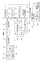
図1はデジタルカメラ2の電気的構成を示す。図1(a)に示すように、デジタルカメラ10は、レンズを含んで構成された光学ユニット22と、レンズの光軸後方に配設されたCCD24と、相関二重サンプリング回路(以下、「CDS」という。)を含んで構成されたアナログ信号処理部26と、入力されたアナログ信号をデジタルデータに変換するアナログ/デジタル変換器(以下、「ADC」という。)28と、所定容量のラインバッファを内蔵し、かつ入力されたデジタル画像データを後述するメモリ72の所定領域に直接記憶させる制御を行うと共に、デジタル画像データに対して各種の画像処理を行うデジタル信号処理部30と、を含んで構成されている。CCD24の出力端はアナログ信号処理部26の入力端に、アナログ信号処理部26の出力端はADC28の入力端に、ADC28の出力端はデジタル信号処理部30の入力端に、各々接続されている。
<First Embodiment>
FIG. 1 shows an electrical configuration of the digital camera 2. As shown in FIG. 1A, a digital camera 10 includes an
ここで、CDSによる相関二重サンプリング処理は、固体撮像素子の出力信号に含まれるノイズ(特に熱雑音)等を軽減することを目的として、固体撮像素子の1画素ごとの出力信号に含まれるフィードスルー成分レベルと画素信号成分レベルとの差をとることにより正確な画素データを得る処理である。 Here, the correlated double sampling processing by CDS is a feed included in the output signal for each pixel of the solid-state image sensor for the purpose of reducing noise (particularly thermal noise) included in the output signal of the solid-state image sensor. This is processing for obtaining accurate pixel data by taking the difference between the through component level and the pixel signal component level.
一方、デジタルカメラ10は、デジタル画像データにより示される画像やメニュー画面等をLCD44に表示させるための信号を生成してLCD44に供給するLCDインタフェース42と、デジタルカメラ10全体の動作を司るCPU(中央処理装置)50と、主として撮影により得られたデジタル画像データを記憶するVRAM(Video RAM)により構成されたメモリ72と、メモリ72に対するアクセスの制御を行うメモリインタフェース70と、スマートメディア(Smart Media(R))により構成されたメモリカード82をデジタルカメラ10でアクセス可能とするための外部メモリインタフェース80と、所定の圧縮形式でデジタル画像データに対して圧縮処理を施す一方、圧縮処理されたデジタル画像データに対して圧縮形式に応じた伸張処理を施す圧縮・伸張処理回路86と、を含んで構成されている。
On the other hand, the digital camera 10 includes an
デジタル信号処理部30、LCDインタフェース42、CPU50、メモリインタフェース70、外部メモリインタフェース80、および圧縮・伸張処理回路86はシステムバスBUSを介して相互に接続されている。従って、CPU50は、デジタル信号処理部30および圧縮・伸張処理回路86の作動の制御、LCD44に対するLCDインタフェース42を介した各種情報の表示、メモリ72およびメモリカード82へのメモリインタフェース70ないし外部メモリインタフェース80を介したアクセスを行うことができる。
The digital
一方、デジタルカメラ10には、主としてCCD24を駆動させるためのタイミング信号を生成してCCD24に供給するタイミングジェネレータ32が備えられており、CCD24の駆動はCPU50によりタイミングジェネレータ32を介して制御される。
On the other hand, the digital camera 10 includes a
さらに、デジタルカメラ10にはモータ駆動部34が備えられており、光学ユニット22に備えられた焦点調整モータ、ズームモータおよび絞り駆動モータの駆動もCPU50によりモータ駆動部34を介して制御される。
Further, the digital camera 10 is provided with a
すなわち、本実施の形態に係る光学ユニット22に含まれるレンズ21は複数枚のレンズを有し、焦点距離の変更(変倍)が可能なズームレンズとして構成されており、図示しないレンズ駆動機構を備えている。このレンズ駆動機構に上記焦点調整モータ、ズームモータおよび絞り駆動モータは含まれるものであり、焦点調整モータ、ズームモータおよび絞り駆動モータは各々CPU50の制御下でモータ駆動部34から供給された駆動信号によって駆動される。
That is, the lens 21 included in the
CPU50は、光学ズーム倍率を変更する際にはズームモータを駆動制御して光学ユニット22に含まれるレンズ21の焦点距離を変化させる。
When changing the optical zoom magnification, the
また、CPU50は、CCD24による撮像によって得られた画像のコントラスト値が最大となるように上記焦点調整モータを駆動制御することによって合焦制御を行う。すなわち、本実施の形態に係るデジタルカメラ10では、合焦制御として、読み取られた画像のコントラストが最大となるようにレンズの位置を設定する、所謂TTL(Through The Lens)方式を採用している。
In addition, the
さらに、レリーズボタン、電源スイッチ、モード切替スイッチ、十字カーソルボタン、および強制発光スイッチの各種ボタン類およびスイッチ類(これらを「操作部90」と総称)はCPU50に接続されており、CPU50は、これらの操作部90に対する操作状態を常時把握できる。
Further, a release button, a power switch, a mode switch, a cross cursor button, and various buttons and switches (generally referred to as “
また、デジタルカメラ10には、ストロボ62とCPU50との間に介在されると共に、CPU50の制御によりストロボ62を発光させるための電力を充電する充電部60が備えられている。さらに、ストロボ62はCPU50にも接続されており、ストロボ62の発光はCPU50によって制御される。
In addition, the digital camera 10 includes a
光学ユニット22に含まれるレンズ駆動機能、CCD24、タイミングジェネレータ32、およびモータ駆動部34が本発明の撮像手段に、アナログ信号処理部26、ADC28、およびデジタル信号処理部30が本発明の信号処理手段に、ストロボ62が本発明の発光手段に、充電部60が本発明の充電手段に、CPU50が本発明の間欠作動手段に、各々相当する。
The lens drive function,
顔検出部91は、メモリ72のデジタル画像データから人物の顔部分を含む領域である顔領域を特定する。顔領域の検出方法としては、例えば本出願人による特許公開2007−124112号公報において開示された技術を適用することができる。
The face detection unit 91 specifies a face area that is an area including a human face from the digital image data in the
すなわち、顔検出部91は、撮影された画像の画像データP0′を読み込み、画像P0′中の顔部分P0f′を検出する。具体的には、特開2005−108195号公報に記載されているように、画像P0′の各画素におけるエッジの向きと大きさを表す勾配ベクトルの向きを表す第1の特徴量を、複数の第1の識別器に入力することによって画像P0′中に顔候補領域が存在するかどうかを判定し、さらに、顔候補領域が存在する場合には、その領域を抽出し、抽出された顔候補領域の各画素における勾配ベクトルの大きさを正規化し、正規化後の勾配ベクトルの大きさと向きを表す第2の特徴量を、第2の識別器に入力することによって、抽出された顔候補領域が真の顔領域であるかどうかを判定し、真の顔領域であれば、その領域を顔部分P0f′として検出することが考えられる。ここで、第1/第2の識別器は、学習用サンプルとなる顔であることがわかっている複数の画像と顔でないことがわかっている複数の画像の各々について算出された第1/第2の特徴量を入力とする、AdaBoost等のマシンラーニングの手法を用いた学習処理によって各々得られたものである。 That is, the face detection unit 91 reads the image data P0 ′ of the photographed image and detects the face portion P0f ′ in the image P0 ′. Specifically, as described in Japanese Patent Application Laid-Open No. 2005-108195, a first feature amount representing the direction of a gradient vector representing the direction and size of an edge in each pixel of the image P0 ′ is set to a plurality of features. By inputting to the first discriminator, it is determined whether or not a face candidate area exists in the image P0 ′. If a face candidate area exists, that area is extracted, and the extracted face candidate is extracted. The face candidate area extracted by normalizing the magnitude of the gradient vector in each pixel of the area and inputting the second feature amount indicating the magnitude and direction of the normalized gradient vector to the second classifier Is a true face area, and if it is a true face area, the area may be detected as a face portion P0f '. Here, the first / second discriminators are calculated for each of a plurality of images that are known to be faces as learning samples and a plurality of images that are known not to be faces. Each of them is obtained by a learning process using a machine learning method such as AdaBoost, which takes the feature quantity 2 as an input.
なお、顔部分P1fの検出方法としては、特表2004−527863号公報に記載されているような固有顔表現と画像自体との相関スコアを用いる方法の他、肌色検出、知識ベース、特徴抽出、テンプレートマッチング、グラフマッチング、統計的手法(ニューラルネットワーク、SVM、HMM)等の様々な公知の手法を用いることができる。 As a method for detecting the face portion P1f, skin color detection, knowledge base, feature extraction, in addition to a method using a correlation score between a specific face expression and the image itself as described in JP-T-2004-527863. Various known methods such as template matching, graph matching, and statistical methods (neural network, SVM, HMM) can be used.
図1(b)に示すように、デジタル信号処理部30は、輝度/色差信号分離部30a、顔大きさ判断部30b、輝度信号ノイズ低減処理部30cを含む。これらの機能については後述する。
As shown in FIG. 1B, the digital
次に、撮影時におけるデジタルカメラ10の全体的な動作について簡単に説明する。 Next, the overall operation of the digital camera 10 during shooting will be briefly described.
光学ユニット22を介した撮像によってCCD24から出力された被写体像を示す信号は順次アナログ信号処理部26に入力されて相関二重サンプリング処理等のアナログ信号処理が施された後にADC28に入力され、ADC28は、アナログ信号処理部26から入力されたR(赤)、G(緑)、B(青)の信号を各々12ビットのR、G、B信号(デジタル画像データ)に変換してデジタル信号処理部30に出力する。
A signal indicating the subject image output from the
デジタル信号処理部30は内蔵しているラインバッファにADC28から順次入力されるデジタル画像データを蓄積して一旦メモリ72の所定領域に格納する。
The digital
メモリ72の所定領域に格納されたデジタル画像データは、CPU50による制御下でデジタル信号処理部30によって読み出され、これらに所定の物理量に応じたデジタルゲインをかけることでホワイトバランス調整を行うと共に、ガンマ処理およびシャープネス処理を行って8ビットのデジタル画像データを生成し、さらにYC信号処理を施して輝度信号Yとクロマ信号Cr、Cb(以下、「YC信号」という。)を生成し、YC信号をメモリ72の上記所定領域とは異なる領域に格納する。
The digital image data stored in a predetermined area of the
なお、LCD44は、CCD24による連続的な撮像によって得られた動画像(スルー画像)を表示してファインダとして使用することができるものとして構成されているが、このようにLCD44をファインダとして使用する場合には、生成したYC信号を、LCDインタフェース42を介して順次LCD44に出力する。これによってLCD44にスルー画像が表示されることになる。
The
ここで、レリーズボタンがユーザによって半押し状態とされた場合、前述のようにAE機能が働いて露出状態が設定された後、AF機能が働いて合焦制御され、その後、引き続き全押し状態とされた場合、この時点でメモリ72に格納されているYC信号を、圧縮・伸張処理回路86によって所定の圧縮形式(本実施の形態では、JPEG形式)で圧縮した後に外部メモリインタフェース80を介してメモリカード82に記録することによって撮影が行われる。
Here, when the release button is pressed halfway by the user, after the AE function is activated and the exposure state is set as described above, the AF function is activated and the focus control is performed. In this case, the YC signal stored in the
なお、CPU50は、当該撮影の際に、強制発光スイッチによって強制発光モードが設定されている場合にはストロボ62を強制的に発光させる。また、強制発光モードが設定されていない場合であっても、CCD24を介して得られた画像情報により示される被写体の測光レベルが所定レベルより低い場合には、CPU50はストロボ62を発光させる。
Note that the
そして、CPU50は、このようなストロボ62の発光に備えて、充電部60による充電量が十分でない場合には、前述のLCD44へのスルー画像の表示動作と並行して充電部60を充電させるストロボ充電処理を実行する。
Then, in preparation for such light emission of the
次に、図2のフローチャートを参照し、カメラ10の実行する美肌処理の流れを説明する。 Next, the flow of the skin beautifying process performed by the camera 10 will be described with reference to the flowchart of FIG.
S1では、輝度/色差信号分離部30aは、ADC28から出力されたオリジナルの撮影画像のR,G,Bデータを輝度信号Y、色差信号Cr、Cbに変換するYC処理を行う。輝度/色差信号分離部30aは、輝度信号Yを輝度信号ノイズ低減処理部30cに送る。
In S1, the luminance / color difference
S2では、顔検出部91は、顔領域の検出を試みる。そして、顔領域の検出に成功した場合はS3に進む。 In S2, the face detection unit 91 tries to detect a face area. If the face area is successfully detected, the process proceeds to S3.
S3では、顔大きさ判断部30bは、顔検出部91の検出した顔領域に基づき、その大きさを取得する。顔大きさ判断部30bは、当該顔領域の大きさが、所定の閾値(例えば、検出した顔領域の横幅が、全画面の画素横幅の1/8)以上であるか否かを判断する。顔領域の大きさが所定の閾値以上である場合はS4、顔領域の大きさが所定の閾値未満である場合はS5に進む。
In S3, the face
S4では、輝度信号ノイズ低減処理部30cは、輝度信号Yの高域成分のノイズ成分を第1のローパスフィルタL1(図3参照)でカットすることで、低域成分の輝度信号Y1を生成する。
In S4, the luminance signal noise
S5では、輝度信号ノイズ低減処理部30cは、輝度信号Yの高域成分のノイズ成分を、第2のローパスフィルタL2(図3参照)でカットすることで、輝度信号Y1を生成する。第2のローパスフィルタL2は、第1のローパスフィルタL1よりも広域カット範囲が狭い。
In S5, the luminance signal noise
S6では、輝度信号ノイズ低減処理部30cは、図示しない減算器により、オリジナルの輝度信号Yから輝度信号Y1を減算して、高周波成分の差分信号Ydを抽出する。
In S6, the luminance signal noise
S7では、差分信号Ydに対し、ノイズリダクションを施し、ノイズ低減した高周波成分の差分信号Y2を生成する。これは例えば、コアリング処理により行われる。すなわち、図4に示すように、差分信号Ydのうち、小さな振幅の信号を通さないようにする処理であり、所定の振幅より小さな振幅の信号をノイズ信号とみなして除去あるいは抑制して出力する処理である。 In S7, noise reduction is applied to the differential signal Yd to generate a high-frequency component differential signal Y2 with reduced noise. This is performed, for example, by a coring process. That is, as shown in FIG. 4, it is a process of preventing a signal having a small amplitude from passing through the difference signal Yd, and a signal having an amplitude smaller than a predetermined amplitude is regarded as a noise signal and is removed or suppressed and output. It is processing.
S8では、輝度信号ノイズ低減処理部30cは、図示しない加算器により、信号Y1と信号Y2とを合成し、最終輝度信号Y3を生成する。最終輝度信号Y3は、オリジナルの輝度信号Yの高周波成分Ydから、小さな振幅の信号(しみやしわに相当)のみが除去され、大きい振幅の信号(背景に相当)は残されたものである。
In S8, the luminance signal noise
この処理による画像処理の具体例を示すと図5・図6のようになる。図5は顔領域の大きさが所定の閾値以上であった場合、図6は顔領域の大きさが所定の閾値未満であった場合を想定している。 Specific examples of image processing by this processing are shown in FIGS. FIG. 5 assumes a case where the size of the face area is greater than or equal to a predetermined threshold, and FIG. 6 assumes a case where the size of the face area is less than the predetermined threshold.
図5(a)に示すように、オリジナルの撮影画像IM1の顔領域の大きさが所定の閾値以上であった場合、図5(b)に例示する第1のローパスフィルタL1を用いて低域成分の輝度信号Y1が得られる。 As shown in FIG. 5A, when the size of the face area of the original captured image IM1 is equal to or greater than a predetermined threshold, the first low-pass filter L1 illustrated in FIG. A component luminance signal Y1 is obtained.
次に、図5(a)に示すように、オリジナルの輝度信号Yから低域成分の輝度信号Y1を減算すると、高周波成分の差分信号Ydが抽出される。これに対してコアリング処理などのノイズリダクションを施し、小振幅のノイズのみ低減した高周波成分の差分信号Y2を得る。そして、低域成分の輝度信号Y1と小振幅のノイズのみ低減した差分信号Y2とを加算することで、最終輝度信号Y3を生成する。このY3とCr、Cbからなる画像データが、美肌処理の施された最終画像データIM2である。 Next, as shown in FIG. 5A, when the low-frequency component luminance signal Y1 is subtracted from the original luminance signal Y, a high-frequency component difference signal Yd is extracted. On the other hand, noise reduction such as coring processing is performed to obtain a high-frequency component difference signal Y2 in which only small amplitude noise is reduced. Then, the final luminance signal Y3 is generated by adding the low frequency component luminance signal Y1 and the difference signal Y2 in which only small amplitude noise is reduced. The image data composed of Y3, Cr, and Cb is final image data IM2 that has undergone skin beautification.
一方、図6(a)に示すように、オリジナルの撮影画像IM1の顔領域の大きさが所定の閾値未満であった場合、図6(b)に例示する第2のローパスフィルタL2によって、輝度信号の高域成分のみがカットされた低域成分の輝度信号Y1が得られる。 On the other hand, as shown in FIG. 6A, when the size of the face area of the original captured image IM1 is less than a predetermined threshold, the second low-pass filter L2 illustrated in FIG. A luminance signal Y1 having a low-frequency component obtained by cutting only the high-frequency component of the signal is obtained.
次に、図6(a)に示すように、オリジナルの輝度信号Yから低域成分の輝度信号Y1を減算すると、高周波成分の差分信号Ydが抽出される。これに対してコアリング処理などのノイズリダクションを施し、小振幅のノイズのみ低減した高周波成分の差分信号Y2を得る。そして、低域成分の輝度信号Y1と差分信号Y2とを加算することで、最終輝度信号Y3を生成する。このY3とCr、Cbからなる画像データが、美肌処理の施された最終画像データIM2である。 Next, as shown in FIG. 6A, when the low-frequency component luminance signal Y1 is subtracted from the original luminance signal Y, a high-frequency component difference signal Yd is extracted. On the other hand, noise reduction such as coring processing is performed to obtain a high-frequency component difference signal Y2 in which only small amplitude noise is reduced. Then, the final luminance signal Y3 is generated by adding the low-frequency component luminance signal Y1 and the difference signal Y2. The image data composed of Y3, Cr, and Cb is final image data IM2 that has undergone skin beautification.
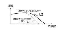
同じ被写体を撮影したとき、顔を大きく撮影した時と小さく撮影した時とでは、顔表面のしわやしみの出方は異なり、小さいときには顔のディテールが落ちることから、顔の大きいときに視認できた細かなしわやしみは、あまり感じられなくなる。 When you shoot the same subject, when you shoot a large face and when you shoot a small face, the appearance of wrinkles and blemishes on the face will be different. Minor wrinkles and blemishes are less felt.
そこで、顔領域が小さいときのローパスフィルタL2は、顔領域が大きいときのローパスフィルタL1よりも高域カット範囲を小さくし、より狭い範囲の高域成分Ydを抽出する。 Therefore, the low-pass filter L2 when the face region is small makes the high-frequency cut range smaller than the low-pass filter L1 when the face region is large, and extracts the high-frequency component Yd in a narrower range.
顔領域が小さい場合の高周波成分の差分信号Ydの周波数範囲は、顔領域が大きい場合よりも狭くなる。しかし、上述したように、小さいときには顔のディテールが落ちることから、顔の大きいときにあった細かなしわやしみは、あまり感じられなくなるから、この狭い範囲でのノイズリダクション処理でも、効果は十分である。 The frequency range of the high-frequency component difference signal Yd when the face area is small is narrower than when the face area is large. However, as mentioned above, since the detail of the face drops when it is small, the fine wrinkles and blemishes that exist when the face is large are not felt so much, so even the noise reduction processing in this narrow range is sufficiently effective It is.
また、顔領域が小さい場合の高周波成分の差分信号Ydの周波数範囲は、顔領域が大きい場合よりも狭くなるから、従来では不必要に消されていた背景部分のディテールが、ノイズリダクションを施してもカットされずに残る。つまり、美肌効果と周囲の背景画質維持の両立が可能である。 Further, since the frequency range of the high-frequency component difference signal Yd when the face area is small is narrower than when the face area is large, the detail of the background portion that has been erased unnecessarily in the past is subjected to noise reduction. Remains uncut. That is, it is possible to achieve both the skin beautifying effect and the surrounding background image quality.
<第2実施形態>
図7は第2実施形態に係るカメラ10のデジタル信号処理部30の詳細構成を示す。デジタル信号処理部30は、色差信号ノイズ低減処理部30dを含む。他の実施形態と同一のブロックには同一の符号を付している。
<Second Embodiment>
FIG. 7 shows a detailed configuration of the digital
図8は、カメラ10の実行する第2実施形態に係る美肌処理の流れを説明する。 FIG. 8 illustrates a flow of skin beautification processing according to the second embodiment performed by the camera 10.
S11では、輝度/色差信号分離部30aは、ADC28から出力されたオリジナルの撮影画像のR,G,Bデータを輝度信号Y、色差信号Cr、Cb(これらの色差信号をまとめてCで表す)に変換するYC処理を行う。輝度/色差信号分離部30aは、色差信号Cを色差信号ノイズ低減処理部30dに送る。
In S11, the luminance / color difference
S12では、顔検出部91は、顔領域の検出を試みる。そして、顔領域の検出に成功した場合はS13に進む。 In S12, the face detection unit 91 tries to detect a face area. If the face area is successfully detected, the process proceeds to S13.
S13では、顔大きさ判断部30bは、顔検出部91の検出した顔領域に基づき、その大きさを取得する。顔大きさ判断部30bは、当該顔領域の大きさが、所定の閾値(例えば、検出した顔領域の横幅が、全画面の画素横幅の1/8)以上であるか否かを判断する。顔領域の大きさが所定の閾値以上である場合はS14、顔領域の大きさが所定の閾値未満である場合はS15に進む。
In S13, the face
S14では、色差信号ノイズ低減処理部30dは、色差信号Cの高域成分のノイズ成分を第1のローパスフィルタL1(図9(b)参照)でカットすることで、低域成分の色差信号C1を生成する。 In S14, the color difference signal noise reduction processing unit 30d cuts the noise component of the high frequency component of the color difference signal C with the first low-pass filter L1 (see FIG. 9B), so that the color difference signal C1 of the low frequency component is obtained. Is generated.
S15では、色差信号ノイズ低減処理部30dは、色差信号Cの高域成分のノイズ成分を、第2のローパスフィルタL2(図10(b)参照)でカットすることで、低域成分の色差信号C1を生成する。第2のローパスフィルタL2は、第1のローパスフィルタL1よりも広域カット範囲が狭い。 In S15, the color difference signal noise reduction processing unit 30d cuts the noise component of the high frequency component of the color difference signal C with the second low-pass filter L2 (see FIG. 10B), so that the color difference signal of the low frequency component is obtained. C1 is generated. The second low-pass filter L2 has a narrower cut range than the first low-pass filter L1.
S16では、色差信号ノイズ低減処理部30dは、図示しない減算器により、オリジナルの色差信号Cから色差信号C1を減算して、高周波成分の差分信号Cdを抽出する。 In S16, the color difference signal noise reduction processing unit 30d subtracts the color difference signal C1 from the original color difference signal C by a subtracter (not shown) to extract a high-frequency component difference signal Cd.
S17では、差分信号Cdに対し、ノイズリダクションを施し、ノイズ低減した高周波成分の差分信号C2を生成する。これは例えば、コアリング処理により行われる。すなわち、差分信号Cdのうち、小さな振幅の信号を通さないようにする処理であり、所定の振幅より小さな振幅の信号をノイズ信号とみなして除去あるいは抑制して出力する処理である。 In S17, noise reduction is performed on the differential signal Cd to generate a high-frequency component differential signal C2 with reduced noise. This is performed, for example, by a coring process. That is, it is a process of preventing a signal having a small amplitude from passing through the difference signal Cd, and is a process of considering a signal having an amplitude smaller than a predetermined amplitude as a noise signal and removing or suppressing the signal.
S18では、色差信号ノイズ低減処理部30dは、図示しない加算器により、色差信号C1と、信号C2と合成し、最終色差信号C3を生成する。最終色差信号C3は、オリジナルの色差信号CをフィルタL1に通して得られた高周波成分Cdから、小さな振幅の信号(しみやしわに相当)のみが除去され、大きい振幅の信号(背景に相当)は残されたものである。 In S18, the color difference signal noise reduction processing unit 30d combines the color difference signal C1 and the signal C2 with an adder (not shown) to generate a final color difference signal C3. From the high-frequency component Cd obtained by passing the original color difference signal C through the filter L1, the final color difference signal C3 is obtained by removing only small amplitude signals (corresponding to spots and wrinkles), and large amplitude signals (corresponding to the background). Is left behind.
この処理による画像処理の具体例を示すと図9・図10のようになる。図9は顔領域の大きさが所定の閾値以上であった場合、図10は顔領域の大きさが所定の閾値未満であった場合を想定している。 Specific examples of image processing by this processing are shown in FIGS. FIG. 9 assumes a case where the size of the face area is greater than or equal to a predetermined threshold, and FIG. 10 assumes a case where the size of the face area is less than the predetermined threshold.
図9(a)に示すように、オリジナルの撮影画像IM1の顔領域の大きさが所定の閾値以上であった場合、図9(b)に例示するような使用する第1のローパスフィルタL1によって、色差信号の高域成分のみがカットされた低域の色差信号C1が得られる。 As shown in FIG. 9A, when the size of the face area of the original captured image IM1 is equal to or larger than a predetermined threshold, the first low-pass filter L1 used as illustrated in FIG. 9B is used. As a result, a low-frequency color difference signal C1 obtained by cutting only the high-frequency component of the color difference signal is obtained.
次に、図9(a)に示すように、オリジナルの色差信号Cから色差信号C1を減算すると、高周波成分の差分信号Cdが抽出される。これに対してコアリング処理などのノイズリダクションを施し、ノイズ低減した高周波成分の差分信号C2を得る。そして、低域の色差信号C1と差分信号C2とを加算することで、最終色差信号C3を生成する。このCとYとからなる画像データが、美肌処理の施された最終画像データIM2である。 Next, as shown in FIG. 9A, when the color difference signal C1 is subtracted from the original color difference signal C, a high-frequency component difference signal Cd is extracted. On the other hand, noise reduction such as coring processing is performed to obtain a high-frequency component differential signal C2 with reduced noise. Then, the final color difference signal C3 is generated by adding the low-frequency color difference signal C1 and the difference signal C2. The image data composed of C and Y is the final image data IM2 subjected to the skin beautification process.
一方、図10(a)に示すように、オリジナルの撮影画像IM1の顔領域の大きさが所定の閾値未満であった場合、図10(b)に例示するような使用する第2のローパスフィルタL2によって、輝度信号の高域成分のみがカットされた低域の色差信号C1が得られる。 On the other hand, as shown in FIG. 10A, when the size of the face area of the original captured image IM1 is less than a predetermined threshold, the second low-pass filter to be used as illustrated in FIG. By L2, a low-frequency color difference signal C1 obtained by cutting only the high-frequency component of the luminance signal is obtained.
次に、図10(a)に示すように、オリジナルの色差信号Cから色差信号C1を減算すると、高周波成分の差分信号Cdが抽出される。これに対してコアリング処理などのノイズリダクションを施し、ノイズ低減した高周波成分の差分信号C2を得る。そして、低域の色差信号C1と差分信号C2とを加算することで、最終色差信号C3を生成する。このCとYとからなる画像データが、美肌処理の施された最終画像データIM2である。 Next, as shown in FIG. 10A, when the color difference signal C1 is subtracted from the original color difference signal C, a high-frequency component difference signal Cd is extracted. On the other hand, noise reduction such as coring processing is performed to obtain a high-frequency component differential signal C2 with reduced noise. Then, the final color difference signal C3 is generated by adding the low-frequency color difference signal C1 and the difference signal C2. The image data composed of C and Y is the final image data IM2 subjected to the skin beautification process.
同じ被写体を撮影したとき、顔を大きく撮影した時と小さく撮影した時とでは、顔表面の色むらの出方は異なり、顔の小さいときには肌の面積が少ないことから、色むらはあまり感じられなくなる。よって、顔の大きさによって、色差信号についてもノイズリダクション効果を変える方が望ましいといえる。 When you shoot the same subject, when you shoot a large face and when you shoot a small face, the appearance of uneven color on the face surface is different, and when the face is small, the skin area is small, so color unevenness is much felt Disappear. Therefore, it can be said that it is desirable to change the noise reduction effect for the color difference signal depending on the size of the face.
そこで、顔領域が小さいときのローパスフィルタL2は、顔領域が大きいときのローパスフィルタL1よりも高域カット範囲を大きくし、顔の大きさによって、より狭い範囲の高域成分Cdを抽出する。 Therefore, the low-pass filter L2 when the face area is small makes the high-frequency cut range larger than the low-pass filter L1 when the face area is large, and extracts a high-frequency component Cd in a narrower range depending on the size of the face.
顔領域が小さい場合の高周波成分の差分信号Cdの周波数範囲は、顔領域が大きい場合よりも狭くなる。しかし、上述したように、小さいときには顔のディテールが落ち、顔の大きいときにあった細かな色むらは、あまり感じられなくなるから、この狭い範囲でのノイズリダクション処理でも、効果は十分であるし、また、従来と異なり、顔が小さい場合は、弱いノイズリダクション処理で済ませるため、背景部分の色にじみやボケの発生も防げる。つまり、美肌効果と周囲の背景画質維持の両立が可能である。 When the face area is small, the frequency range of the high-frequency component difference signal Cd is narrower than when the face area is large. However, as described above, the detail of the face is reduced when it is small, and the fine color irregularities that existed when the face is large cannot be felt so much. In addition, unlike a conventional case, when the face is small, a weak noise reduction process can be used, so that it is possible to prevent the occurrence of color bleeding and blurring in the background portion. That is, it is possible to achieve both the skin beautifying effect and the surrounding background image quality.
<第3実施形態>
図11は第3実施形態に係るカメラ10のデジタル信号処理部30の詳細構成を示す。デジタル信号処理部30は、輝度信号周波数分解部30e、各周波数帯域輝度信号ノイズ低減処理部30fを含む。他の実施形態と同一のブロックには同一の符号を付している。
<Third Embodiment>
FIG. 11 shows a detailed configuration of the digital
図12は、カメラ10の実行する第3実施形態に係る美肌処理の流れを説明する。 FIG. 12 illustrates a flow of skin beautification processing according to the third embodiment executed by the camera 10.
S21,S22は、それぞれS1、S2と同様である。 S21 and S22 are the same as S1 and S2, respectively.
S23では、各周波数帯域輝度信号ノイズ低減処理部30fは、輝度信号Yから、段階的に区分された複数の周波数帯域(例えば高・中・低の3段階)に対応する周波数成分を、抽出する。
In S23, each frequency band luminance signal noise
S24は、S2と同様、顔領域の検出が成功したか否かを判断し、成功したと判断した場合、S25に進む。 In S24, as in S2, it is determined whether or not the detection of the face area is successful. If it is determined that the detection is successful, the process proceeds to S25.
S25では、顔大きさ判断部30bは、当該顔領域の大きさが、所定の閾値(例えば、検出した顔領域の横幅が、全画面の画素横幅の1/8)以上であるか否かを判断する。顔領域の大きさが所定の閾値以上である場合はS26、顔領域の大きさが所定の閾値未満である場合はS27に進む。
In S25, the face
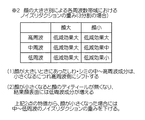
S26では、輝度信号Yの各周波数成分に対し、顔が大きい場合の第1のノイズリダクションを施す。例えば、図13の重みテーブルで示すように、高周波数帯域の成分にはノイズ低減効果の大きい処理(例えばコアリング処理でカットする低周波数領域を大きくする)を行い、中周波数帯域の成分にはノイズ低減効果の大きい処理を行い、低周波数帯域の成分にはノイズ低減効果の大きい処理を行うといったように、周波数帯域ごとに対応するノイズリダクションの重みを決め、それに応じて周波数帯域ごとに重みづけされたノイズリダクション処理を各周波数成分に施すことで、輝度信号Yから、しみやしわに相当する周波数成分のみを取り除く。 In S26, the first noise reduction when the face is large is performed on each frequency component of the luminance signal Y. For example, as shown in the weight table of FIG. 13, processing with a large noise reduction effect is performed on the components in the high frequency band (for example, the low frequency region cut by coring processing is increased), and the components in the middle frequency band are processed. The noise reduction weight corresponding to each frequency band is determined, such as processing with a large noise reduction effect, and processing with a large noise reduction effect for low frequency band components, and weighting for each frequency band accordingly. By applying the noise reduction processing thus performed to each frequency component, only the frequency components corresponding to the spots and wrinkles are removed from the luminance signal Y.
S27では、輝度信号Yの各周波数成分に対し、顔が小さい場合の第2のノイズリダクションを施す。例えば、図13のテーブルで示すように、高周波数帯域にはノイズ低減効果の大きい処理(例えばコアリング処理でカットする周波数帯域を大きくする)を行い、中周波数帯域にはノイズ低減効果の中間程度の処理(例えばコアリング処理でカットする周波数帯域を中程度にする)を行い、低周波数帯域にはノイズ低減効果の小さい処理(例えばコアリング処理でカットする周波数帯域を小さくする)を行うといったように、周波数帯域ごとに対応するノイズリダクションの重みを決め、それに応じて周波数帯域ごとに重みづけされたノイズリダクション処理を各周波数成分に施すことで、輝度信号Yから、しみやしわに相当する周波数部分のみを取り除く。 In S27, the second noise reduction when the face is small is performed on each frequency component of the luminance signal Y. For example, as shown in the table of FIG. 13, processing with a large noise reduction effect is performed in the high frequency band (for example, the frequency band to be cut by the coring process is increased), and the intermediate frequency band has an intermediate noise reduction effect. (For example, the frequency band cut by the coring process is made moderate), and the low frequency band is processed with a small noise reduction effect (for example, the frequency band cut by the coring process is reduced). In addition, by determining the noise reduction weight corresponding to each frequency band, and applying noise reduction processing weighted for each frequency band accordingly to each frequency component, the frequency corresponding to the spots and wrinkles from the luminance signal Y Remove only the part.
この処理による画像処理の具体例を示すと図14・図15のようになる。図14は顔領域の大きさが所定の閾値以上であった場合、図15は顔領域の大きさが所定の閾値未満であった場合を想定している。 Specific examples of image processing by this processing are shown in FIGS. FIG. 14 assumes a case where the size of the face area is equal to or greater than a predetermined threshold, and FIG. 15 assumes a case where the size of the face area is less than the predetermined threshold.
図14に示すように、オリジナル画像データIM1から輝度信号Yを抽出し、さらに、輝度信号Yを高中低の3つの周波数帯域に分離する。次に、各周波数帯の小振幅成分をノイズ(しみ、しわ)とみなし、図13のテーブルに従って各周波数帯域ごとにコアリングの重みづけをして、各周波数帯域ごとにノイズリダクション処理を施す。 As shown in FIG. 14, the luminance signal Y is extracted from the original image data IM1, and further, the luminance signal Y is separated into three frequency bands of high, medium and low. Next, the small amplitude component of each frequency band is regarded as noise (stains and wrinkles), the coring is weighted for each frequency band according to the table of FIG. 13, and noise reduction processing is performed for each frequency band.
図15に示すように、オリジナル画像データIM1から輝度成分Yを抽出し、さらに、輝度成分Yを高中低の3つの周波数帯域に分離する。次に、各周波数帯の小振幅成分をノイズ(しみ、しわ)とみなし、図13のテーブルに従って各周波数帯域ごとにコアリングの重みづけをして、各周波数帯域ごとにノイズリダクション処理を施す。 As shown in FIG. 15, the luminance component Y is extracted from the original image data IM1, and the luminance component Y is further separated into three frequency bands of high, middle and low. Next, the small amplitude component of each frequency band is regarded as noise (stains and wrinkles), the coring is weighted for each frequency band according to the table of FIG. 13, and noise reduction processing is performed for each frequency band.
顔領域が小さい場合、ノイズ成分(しみ、しわ)は、高周波数側にシフトする。これは、顔領域の解像度が低下し、高解像度下ではくっきりしていたノイズ成分がぼやけてくる、すなわち、画像としての顔領域表面の周波数特性が、顔領域が小さくなるにつれて低周波数側に集まるためである。 When the face area is small, noise components (stains and wrinkles) shift to the high frequency side. This is because the resolution of the face area decreases and the noise components that were sharp under high resolution become blurred, that is, the frequency characteristics of the face area surface as an image gather on the lower frequency side as the face area becomes smaller Because.
顔領域が小さい場合、高周波帯域側のノイズリダクションのみで十分所期の効果が達成でき、低周波帯域側のノイズリダクションは、あまり意味がない。よって、顔領域が小さい場合、低周波帯域側のノイズリダクションに対して特に大きな重みづけをする。 When the face area is small, the desired effect can be achieved with only noise reduction on the high frequency band side, and noise reduction on the low frequency band side is not very meaningful. Therefore, when the face area is small, a particularly large weight is given to noise reduction on the low frequency band side.
このように、顔の大きさに応じて、ノイズとして除去する輝度信号の周波数帯域を変えることで、より精度の高いノイズリダクション効果を得ることができる。 Thus, by changing the frequency band of the luminance signal to be removed as noise according to the size of the face, a more accurate noise reduction effect can be obtained.
<第4実施形態>
図17は第4実施形態に係るカメラ10のデジタル信号処理部30の詳細構成を示す。デジタル信号処理部30は、色差信号周波数分解部30g、各周波数帯域色差信号ノイズ低減処理部30hを含む。他の実施形態と同一のブロックには同一の符号を付している。
<Fourth embodiment>
FIG. 17 shows a detailed configuration of the digital
図18は、カメラ10の実行する第4実施形態に係る美肌処理の流れを説明する。 FIG. 18 illustrates a flow of skin beautification processing according to the fourth embodiment performed by the camera 10.
S31,S32は、それぞれS1、S2と同様である。 S31 and S32 are the same as S1 and S2, respectively.
S33では、各周波数帯域色差信号ノイズ低減処理部30hは、色差信号Cから、段階的に区分された複数の周波数帯域(例えば、「高」、「中」、「低」の3つの帯域)に対応する周波数成分を、抽出する。
In S33, each frequency band chrominance signal noise
S34は、S2と同様、顔領域の検出が成功したか否かを判断し、成功したと判断した場合、S35に進む。 In S34, as in S2, it is determined whether or not the detection of the face area is successful. If it is determined that the detection is successful, the process proceeds to S35.
S35では、顔大きさ判断部30bは、当該顔領域の大きさが、所定の閾値(例えば、検出した顔領域の横幅が、全画面の画素横幅の1/8)以上であるか否かを判断する。顔領域の大きさが所定の閾値以上である場合はS36、顔領域の大きさが所定の閾値未満である場合はS37に進む。
In S35, the face
S36では、色差信号Cの各周波数成分に対し、顔が大きい場合の第1のノイズリダクションを施す。例えば、図18のテーブルで示すように、高周波数帯域にはノイズ低減効果の大きい処理(例えばコアリング処理でカットする低周波数領域を大きくする)を行い、中周波数帯域にはノイズ低減効果の大きい処理を行い、低周波数帯域にはノイズ低減効果の大きい処理を行うといったように、周波数帯域ごとに対応するノイズリダクションの重みを決め、それに応じて周波数成分ごとに重みづけされたノイズリダクション処理を施す。 In S36, the first noise reduction when the face is large is performed on each frequency component of the color difference signal C. For example, as shown in the table of FIG. 18, processing with a large noise reduction effect is performed in the high frequency band (for example, the low frequency region cut by the coring process is increased), and the noise reduction effect is large in the middle frequency band. The noise reduction weight corresponding to each frequency band is determined and the noise reduction process weighted for each frequency component is performed accordingly, such as processing with a large noise reduction effect in the low frequency band. .
S37では、色差信号Cの各周波数成分に対し、顔が小さい場合の第2のノイズリダクションを施す。例えば、図18のテーブルで示すように、高周波数帯域にはノイズ低減効果の大きい処理(例えばコアリング処理でカットする周波数帯域を大きくする)を行い、中周波数帯域にはノイズ低減効果の中間程度の処理(例えばコアリング処理でカットする周波数帯域を中程度にする)を行い、低周波数帯域にはノイズ低減効果の小さい処理(例えばコアリング処理でカットする周波数帯域を小さくする)を行うといったように、周波数帯域ごとに対応するノイズリダクションの重みを決め、それに応じて周波数成分ごとに重みづけされたノイズリダクション処理を施す。 In S37, the second noise reduction when the face is small is applied to each frequency component of the color difference signal C. For example, as shown in the table of FIG. 18, processing with a large noise reduction effect is performed in the high frequency band (for example, the frequency band to be cut by coring processing is increased), and the intermediate frequency band has an intermediate noise reduction effect. (For example, the frequency band cut by the coring process is made moderate), and the low frequency band is processed with a small noise reduction effect (for example, the frequency band cut by the coring process is reduced). In addition, a noise reduction weight corresponding to each frequency band is determined, and a noise reduction process weighted for each frequency component is performed accordingly.
この処理による画像処理の具体例を示すと図19・図20のようになる。図19は顔領域の大きさが所定の閾値以上であった場合、図20は顔領域の大きさが所定の閾値未満であった場合を想定している。 Specific examples of image processing by this processing are as shown in FIGS. FIG. 19 assumes a case where the size of the face area is greater than or equal to a predetermined threshold, and FIG. 20 assumes a case where the size of the face area is less than the predetermined threshold.
図19に示すように、オリジナル画像データIM1から色差信号Cを抽出し、さらに、高中低の3つの周波数帯域に分離する。次に、各周波数帯の小振幅成分をノイズ(しみ、しわ)とみなし、図18のテーブルに従って各周波数帯域ごとにコアリングの重みづけをして、ノイズリダクション処理を施す。 As shown in FIG. 19, the color difference signal C is extracted from the original image data IM1, and further separated into three frequency bands of high, middle, and low. Next, the small amplitude component of each frequency band is regarded as noise (stains and wrinkles), and coring is weighted for each frequency band in accordance with the table of FIG. 18, and noise reduction processing is performed.
図20に示すように、オリジナル画像データIM1から色差信号Cを抽出し、さらに、高中低の3つの周波数帯域に分離する。次に、各周波数帯の小振幅成分をノイズ(しみ、しわ)とみなし、図18のテーブルに従って各周波数帯域ごとにコアリングの重みづけをして、ノイズリダクション処理を施す。 As shown in FIG. 20, the color difference signal C is extracted from the original image data IM1, and further separated into three frequency bands of high, middle, and low. Next, the small amplitude component of each frequency band is regarded as noise (stains and wrinkles), and coring is weighted for each frequency band in accordance with the table of FIG. 18, and noise reduction processing is performed.
顔領域が小さい場合、ノイズ成分(しみ、しわ)は、高周波数側にシフトする。これは、顔領域の解像度が低下し、高解像度下ではくっきりしていたノイズ成分がぼやけてくるすなわち、画像としての顔領域表面の周波数特性が、顔領域が小さくなるにつれて低周波数側に集まるためである。 When the face area is small, noise components (stains and wrinkles) shift to the high frequency side. This is because the resolution of the face area decreases and the noise components that were sharp under high resolution become blurred, that is, the frequency characteristics of the face area surface as an image gather on the lower frequency side as the face area becomes smaller. It is.
顔領域が小さい場合、高周波帯域側のノイズリダクションのみで十分所期の効果が達成でき、低周波帯域側のノイズリダクションは、あまり意味がない。よって、顔領域が小さい場合、低周波帯域側のノイズリダクションに対して特に重みづけをする。 If the face area is small, the desired effect can be achieved with only noise reduction on the high frequency band side, and noise reduction on the low frequency band side is not very meaningful. Therefore, when the face area is small, the noise reduction on the low frequency band side is particularly weighted.
このように、顔の大きさに応じて、ノイズとして除去する色差信号の周波数帯域を変えることで、より精度の高いノイズリダクション効果を得ることができる。 In this way, a more accurate noise reduction effect can be obtained by changing the frequency band of the color difference signal to be removed as noise in accordance with the size of the face.
<第5実施形態>
図21は第5実施形態に係るカメラ10のデジタル信号処理部30の詳細構成を示す。他の実施形態と同一のブロックには同一の符号を付している。
<Fifth Embodiment>
FIG. 21 shows a detailed configuration of the digital
図22は、カメラ10の実行する第5実施形態に係る美肌処理の流れを説明する。 FIG. 22 illustrates a flow of skin beautification processing according to the fifth embodiment performed by the camera 10.
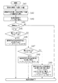
S41〜S44は、S21〜S24と同様である。 S41 to S44 are the same as S21 to S24.
S45では、顔領域の大きさが「大きい」か否かを判断する。例えば図23の顔サイズ判定テーブルに従い、顔領域の横サイズと全画像の横サイズの比が7/8以上であれば、大きいと判断する。そして、大きいと判断した場合、S46に進む。 In S45, it is determined whether or not the size of the face area is “large”. For example, according to the face size determination table of FIG. 23, if the ratio of the horizontal size of the face area to the horizontal size of all images is 7/8 or more, it is determined to be large. If it is determined that the value is large, the process proceeds to S46.
S46では、各周波数帯域輝度信号ノイズ低減処理部30fは、顔領域の大きさが「大きい」場合に対応する輝度信号Yの各周波数帯の重みを決定し、その重みに従って各周波数成分にノイズリダクション処理を施す。図24は、顔領域の大きさに対応する重みを規定した重みテーブルの一例を示す。S46では、「大きい」場合に対応する重み、すなわち高周波帯域では「大」、中周波帯域では「大」、小周波帯域では「大」の重みが与えられる。これはS26と同様である。
In S46, each frequency band luminance signal noise
S47では、顔領域の大きさが「小さい」か否かを判断する。例えば図23の顔サイズ判定テーブルに従い、顔領域の横サイズと全画像の横サイズの比が1/8未満であれば、小さいと判断する。そして、小さいと判断した場合、S48に進む。小さいと判断しない場合、S49に進む。 In S47, it is determined whether or not the size of the face area is “small”. For example, according to the face size determination table of FIG. 23, if the ratio of the horizontal size of the face area to the horizontal size of all images is less than 1/8, it is determined that the size is small. And when it is judged that it is small, it progresses to S48. If not determined to be small, the process proceeds to S49.
S48では、各周波数帯域輝度信号ノイズ低減処理部30fは、顔領域の大きさが「大きい」場合に対応する輝度信号Yの各周波数帯の重みを決定し、その重みに従って各周波数成分にノイズリダクション処理を施す。
In S48, each frequency band luminance signal noise
図24は、顔領域の大きさに対応する重みを規定した重みテーブルの一例を示す。S48では、顔が「小さい」場合に対応する重み、すなわち高周波帯域では「大」、中周波帯域では「中」、小周波帯域では「小」の重みが与えられる。これはS27と同様である。 FIG. 24 shows an example of a weight table that defines weights corresponding to the size of the face area. In S48, a weight corresponding to a case where the face is “small”, that is, a weight of “large” in the high frequency band, “medium” in the medium frequency band, and “small” in the small frequency band is given. This is the same as S27.
S49では、顔領域の大きさが「大きい」場合に対応する各周波数帯の重みと、「小さい」場合に対応する各周波数帯の重みとを線形補間することで、顔領域の大きさが「中間」場合に対応する各周波数帯の重みを算出する。 In S49, by linearly interpolating the weight of each frequency band corresponding to the case where the face area size is “large” and the weight of each frequency band corresponding to the case where the face area is “small”, the size of the face area becomes “ The weight of each frequency band corresponding to the “intermediate” case is calculated.
例えば、図25が、顔領域の大きさが「大きい」場合に対応する輝度信号Yの高、中、低の各周波数帯の重みをパラメータ「Y_BL_H」、「Y_BL_M」、「Y_BL_L」で、あるいは「小さい」場合に対応する高、中、低の各周波数帯の重みをパラメータ「Y_BS_H」、「Y_BS_M」、「Y_BS_L」で、一般的に表したものとする。この場合、図26に例示するような、各周波数帯ごとの線形補間式により、高、中、低の各周波帯に対応する重み「Y_BX_H」、「Y_BX_M」、「Y_BX_L」を算出する。 For example, in FIG. 25, the weights of the high, medium, and low frequency bands of the luminance signal Y corresponding to the case where the size of the face area is “large” are represented by the parameters “Y_BL_H”, “Y_BL_M”, “Y_BL_L”, or The weights of the high, medium, and low frequency bands corresponding to the case of “small” are generally represented by parameters “Y_BS_H”, “Y_BS_M”, and “Y_BS_L”. In this case, the weights “Y_BX_H”, “Y_BX_M”, and “Y_BX_L” corresponding to the high, medium, and low frequency bands are calculated by the linear interpolation formula for each frequency band as illustrated in FIG.
これにより、顔の大きさが中間の場合でも、周波数帯に応じて輝度信号Yの適切なノイズリダクションが可能であり、顔の大きさが中途半端な場合に不適切なパラメータでノイズリダクションがされてハンチング現象が発生することを防げる。 As a result, even when the face size is intermediate, it is possible to perform appropriate noise reduction of the luminance signal Y according to the frequency band, and when the face size is halfway, noise reduction is performed with an inappropriate parameter. Hunting phenomenon can be prevented.
<第6実施形態>
図27は第6実施形態に係るカメラ10のデジタル信号処理部30の詳細構成を示す。他の実施形態と同一のブロックには同一の符号を付している。
<Sixth Embodiment>
FIG. 27 shows a detailed configuration of the digital
図28は、カメラ10の実行する第6実施形態に係る美肌処理の流れを説明する。 FIG. 28 illustrates the flow of skin beautification processing according to the sixth embodiment performed by the camera 10.
S51〜S54は、S31〜S34と同様である。 S51 to S54 are the same as S31 to S34.
S55では、顔領域の大きさが「大きい」か否かを判断する。例えば図29の顔サイズ判断テーブルに従い、顔領域の横サイズと全画像の横サイズの比が7/8以上であれば、大きいと判断する。そして、大きいと判断した場合、S56に進む。 In S55, it is determined whether or not the size of the face area is “large”. For example, according to the face size determination table of FIG. 29, if the ratio of the horizontal size of the face area to the horizontal size of all images is 7/8 or more, it is determined to be large. If it is determined that the value is large, the process proceeds to S56.
S56では、各周波数帯域色差信号ノイズ低減処理部30hは、顔領域の大きさが「大きい」場合に対応する色差信号Cの各周波数帯の重みを決定し、その重みに従って各周波数成分にノイズリダクション処理を施す。図30は、顔領域の大きさに対応する重みを規定したテーブルの一例を示す。S56では、「大きい」場合に対応する重み、すなわち高周波帯域では「大」、中周波帯域では「大」、小周波帯域では「大」の重みが与えられる。これはS36と同様である。
In S56, each frequency band chrominance signal noise
S57では、顔領域の大きさが「小さい」か否かを判断する。例えば図30の顔サイズ判断テーブルに従い、顔領域の横サイズと全画像の横サイズの比が1/8未満であれば、小さいと判断する。そして、小さいと判断した場合、S58に進む。小さいと判断しない場合、S59に進む。 In S57, it is determined whether or not the size of the face area is “small”. For example, according to the face size determination table of FIG. 30, if the ratio of the horizontal size of the face area to the horizontal size of all images is less than 1/8, it is determined to be small. And when it is judged that it is small, it progresses to S58. If not determined to be small, the process proceeds to S59.
S58では、各周波数帯域色差信号ノイズ低減処理部30hは、顔領域の大きさが「大きい」場合に対応する色差信号Cの各周波数帯の重みを決定し、その重みに従って各周波数成分にノイズリダクション処理を施す。
In S58, each frequency band color difference signal noise
図31は、顔領域の大きさに対応する重みを規定した重みテーブルの一例を示す。S56では、「大きい」場合に対応する重み、すなわち高周波帯域では「大」、中周波帯域では「中」、小周波帯域では「小」の重みが与えられる。これはS37と同様である。 FIG. 31 shows an example of a weight table that defines weights corresponding to the size of the face area. In S56, a weight corresponding to the case of “large”, that is, a weight of “large” in the high frequency band, “medium” in the medium frequency band, and “small” in the small frequency band is given. This is the same as S37.
S59では、顔領域の大きさが「中間」場合に対応する各周波数帯の重みおよび「小さい」場合に対応する各周波数帯の重みを、線形補間することで、顔領域の大きさが「中間」場合に対応する各周波数帯の重みを算出する。 In S59, the weight of each frequency band corresponding to the case where the face area size is “intermediate” and the weight of each frequency band corresponding to the case where the face area is “small” are linearly interpolated, so that the face area size becomes “medium”. The weight of each frequency band corresponding to the case is calculated.
例えば、図31が、顔領域の大きさが「大きい」場合に対応する色差信号Cの高、中、低の各周波数帯の重みをパラメータ「C_BL_H」、「C_BL_M」、「C_BL_L」で、あるいは「小さい」場合に対応する高、中、低の各周波数帯の重みをパラメータ「C_BS_H」、「C_BS_M」、「C_BS_L」で、一般的に表したものとする。この場合、図32に例示するような各周波数帯ごとの線形補間式により、高、中、低の各周波帯に対応する重み「C_BX_H」、「C_BX_M」、「C_BX_L」を算出する。 For example, FIG. 31 shows the weights of the high, medium, and low frequency bands of the color difference signal C corresponding to the case where the size of the face area is “large” by the parameters “C_BL_H”, “C_BL_M”, “C_BL_L”, or The weights of the high, medium, and low frequency bands corresponding to the case of “small” are generally represented by parameters “C_BS_H”, “C_BS_M”, and “C_BS_L”. In this case, the weights “C_BX_H”, “C_BX_M”, and “C_BX_L” corresponding to the high, medium, and low frequency bands are calculated by the linear interpolation formula for each frequency band as illustrated in FIG.
これにより、顔の大きさが中間の場合でも、周波数帯に応じて色差信号Cの適切なノイズリダクションが可能であり、顔の大きさが中途半端な場合に不適切なパラメータでノイズリダクションがされてハンチング現象が発生することを防げる。 As a result, even when the face size is intermediate, it is possible to perform appropriate noise reduction of the color difference signal C according to the frequency band. When the face size is halfway, noise reduction is performed with an inappropriate parameter. Hunting phenomenon can be prevented.
30:デジタル信号処理部、30a:輝度/色差信号分離部、30b:顔大きさ判断部、30c:輝度信号ノイズ低減処理部、30d:色差信号ノイズ低減処理部、30e:輝度信号周波数分解部、30f:各周波数帯域輝度信号ノイズ低減処理部、30g:色差信号周波数分解部、30h:各周波数帯域色差信号ノイズ低減処理部、91:顔検出部 30: Digital signal processing unit, 30a: Luminance / color difference signal separation unit, 30b: Face size determination unit, 30c: Luminance signal noise reduction processing unit, 30d: Color difference signal noise reduction processing unit, 30e: Luminance signal frequency decomposition unit, 30f: Each frequency band luminance signal noise reduction processing unit, 30g: Color difference signal frequency decomposition unit, 30h: Each frequency band color difference signal noise reduction processing unit, 91: Face detection unit
Claims (4)
前記画像から顔領域を検出するステップと、
前記検出された顔領域の大きさに基づいて前記画像の色差信号に対する所定のコアリング処理を施す周波数帯域を決定するステップと、
前記画像の色差信号から前記決定された周波数帯域を抽出するステップと、
前記画像の色差信号から抽出された周波数帯域に前記所定のコアリング処理を施すステップと、
を含む画像処理方法。 Inputting an image;
Detecting a face region from the image;
Determining a frequency band for performing a predetermined coring process on the color difference signal of the image based on the size of the detected face area;
Extracting the determined frequency band from the color difference signal of the image;
Applying the predetermined coring process to a frequency band extracted from the color difference signal of the image;
An image processing method including:
前記画像の色差信号を所定の複数の周波数帯域に応じた複数の周波数成分に分離するステップと、
前記画像から顔領域を検出するステップと、
前記検出された顔領域の大きさに基づいてコアリング処理を施す分離周波数成分ごとの
重みを決定するステップと、
前記決定された分離周波数成分ごとの重みに応じ、前記分離周波数成分ごとに所定のコ
アリング処理を施すステップと、
を含む画像処理方法。 Inputting an image;
Separating the color difference signal of the image into a plurality of frequency components corresponding to a plurality of predetermined frequency bands;
Detecting a face region from the image;
Determining a weight for each separated frequency component to be coring based on the size of the detected face area;
Performing a predetermined coring process for each separated frequency component according to the determined weight for each separated frequency component;
An image processing method including:
前記画像から顔領域を検出する顔検出部と、
前記検出された顔領域の大きさに基づいて前記画像の色差信号に対する所定のコアリング処理を施す周波数帯域を決定する周波数帯域決定部と、
前記画像の色差信号から前記決定された周波数帯域を抽出する周波数帯域抽出部と、
前記画像の色差信号から抽出された周波数帯域に前記所定のコアリング処理を施すノイズリダクション処理部と、
を備える画像処理装置。 An image input unit for inputting an image;
A face detection unit for detecting a face region from the image;
A frequency band determining unit that determines a frequency band for performing a predetermined coring process on the color difference signal of the image based on the size of the detected face area;
A frequency band extractor for extracting the determined frequency band from the color difference signal of the image;
A noise reduction processing unit that performs the predetermined coring processing on the frequency band extracted from the color difference signal of the image;
An image processing apparatus comprising:
前記画像の色差信号を所定の複数の周波数帯域に応じた複数の周波数成分に分離する分離部と、
前記画像から顔領域を検出する顔検出部と、
前記検出された顔領域の大きさに基づいてコアリング処理を施す分離周波数成分ごとの重みを決定する重み決定部と、
前記決定された分離周波数成分ごとの重みに応じ、前記分離周波数成分ごとに所定のコアリング処理を施すノイズリダクション処理部と、
を備える画像処理装置。 An image input unit for inputting an image;
A separation unit that separates the color difference signal of the image into a plurality of frequency components according to a plurality of predetermined frequency bands;
A face detection unit for detecting a face region from the image;
A weight determining unit that determines a weight for each separated frequency component to be subjected to coring processing based on the size of the detected face area;
A noise reduction processing unit that performs a predetermined coring process for each separated frequency component according to the determined weight for each separated frequency component;
An image processing apparatus comprising:
Priority Applications (2)
| Application Number | Priority Date | Filing Date | Title |
|---|---|---|---|
| JP2007184826A JP4666179B2 (en) | 2007-07-13 | 2007-07-13 | Image processing method and image processing apparatus |
| US12/170,618 US8244059B2 (en) | 2007-07-13 | 2008-07-10 | Image processing method, apparatus, recording medium, and image pickup apparatus |
Applications Claiming Priority (1)
| Application Number | Priority Date | Filing Date | Title |
|---|---|---|---|
| JP2007184826A JP4666179B2 (en) | 2007-07-13 | 2007-07-13 | Image processing method and image processing apparatus |
Publications (3)
| Publication Number | Publication Date |
|---|---|
| JP2009020834A JP2009020834A (en) | 2009-01-29 |
| JP2009020834A5 JP2009020834A5 (en) | 2010-10-28 |
| JP4666179B2 true JP4666179B2 (en) | 2011-04-06 |
Family
ID=40253175
Family Applications (1)
| Application Number | Title | Priority Date | Filing Date |
|---|---|---|---|
| JP2007184826A Expired - Fee Related JP4666179B2 (en) | 2007-07-13 | 2007-07-13 | Image processing method and image processing apparatus |
Country Status (2)
| Country | Link |
|---|---|
| US (1) | US8244059B2 (en) |
| JP (1) | JP4666179B2 (en) |
Cited By (1)
| Publication number | Priority date | Publication date | Assignee | Title |
|---|---|---|---|---|
| US9361671B2 (en) | 2013-09-27 | 2016-06-07 | Sony Corporation | Image processing apparatus, image processing method, and program |
Families Citing this family (13)
| Publication number | Priority date | Publication date | Assignee | Title |
|---|---|---|---|---|
| JPWO2010044214A1 (en) * | 2008-10-14 | 2012-03-08 | パナソニック株式会社 | Face recognition device and face recognition method |
| TWI417811B (en) * | 2008-12-31 | 2013-12-01 | Altek Corp | The Method of Face Beautification in Digital Image |
| JP2010283523A (en) * | 2009-06-03 | 2010-12-16 | Nec Casio Mobile Communications Ltd | Image processor and program |
| JP5517504B2 (en) * | 2009-06-29 | 2014-06-11 | キヤノン株式会社 | Image processing apparatus, image processing method, and program |
| KR101613616B1 (en) | 2009-07-17 | 2016-04-19 | 삼성전자주식회사 | Digital camera adaptively setting cosmetic function and controlling method thereof |
| JP5235976B2 (en) * | 2010-05-31 | 2013-07-10 | 株式会社ソニー・コンピュータエンタテインメント | Video playback method and video playback apparatus |
| KR101769543B1 (en) * | 2011-01-04 | 2017-08-31 | 인하대학교 산학협력단 | Apparatus and method for improving image resolution using sharpness and color saturation |
| JP5273208B2 (en) * | 2011-06-07 | 2013-08-28 | オムロン株式会社 | Image processing apparatus, image processing method, and control program |
| CN104067311B (en) * | 2011-12-04 | 2017-05-24 | 数码装饰有限公司 | Digital makeup |
| CN103999096B (en) * | 2011-12-16 | 2017-12-08 | 英特尔公司 | Picture quality for the reduction of video data background area |
| JP6267502B2 (en) * | 2013-12-10 | 2018-01-24 | キヤノン株式会社 | IMAGING DEVICE, IMAGING DEVICE CONTROL METHOD, AND PROGRAM |
| CN105704395B (en) * | 2016-04-05 | 2018-09-14 | 广东欧珀移动通信有限公司 | Photographic method and camera arrangement |
| CN109035177B (en) * | 2018-08-27 | 2020-11-20 | 三星电子(中国)研发中心 | Photo processing method and device |
Citations (7)
| Publication number | Priority date | Publication date | Assignee | Title |
|---|---|---|---|---|
| JPS6359266A (en) * | 1986-08-29 | 1988-03-15 | アグファ−ゲ−ヴェルト・アクチエンゲゼルシャフト | Method and apparatus for regulating picture contrast |
| JPH09233423A (en) * | 1996-02-27 | 1997-09-05 | Fuji Photo Film Co Ltd | Image data converting method for digital printer |
| JPH11339035A (en) * | 1998-05-21 | 1999-12-10 | Fuji Photo Film Co Ltd | Method for deciding image processing parameter and device therefor |
| JP2004303193A (en) * | 2003-03-20 | 2004-10-28 | Omron Corp | Image processor |
| JP2005196270A (en) * | 2003-12-26 | 2005-07-21 | Konica Minolta Photo Imaging Inc | Image processing method, image processing equipment, and image processing program |
| JP2007087234A (en) * | 2005-09-26 | 2007-04-05 | Fujifilm Corp | Image processing method and apparatus, and program |
| JP2008258830A (en) * | 2007-04-03 | 2008-10-23 | Nikon Corp | Image processing apparatus, imaging apparatus, and program |
Family Cites Families (5)
| Publication number | Priority date | Publication date | Assignee | Title |
|---|---|---|---|---|
| JPH0566795A (en) * | 1991-09-06 | 1993-03-19 | Gijutsu Kenkyu Kumiai Iryo Fukushi Kiki Kenkyusho | Noise suppressing device and its adjustment device |
| JP3880862B2 (en) * | 2002-01-29 | 2007-02-14 | 富士フイルムホールディングス株式会社 | Imaging device |
| JP4455897B2 (en) * | 2004-02-10 | 2010-04-21 | 富士フイルム株式会社 | Image processing method, apparatus, and program |
| JP3965402B2 (en) * | 2004-08-23 | 2007-08-29 | 富士フイルム株式会社 | Noise reduction apparatus and method, and noise reduction program |
| JP2006318103A (en) * | 2005-05-11 | 2006-11-24 | Fuji Photo Film Co Ltd | Image processor, image processing method, and program |
-
2007
- 2007-07-13 JP JP2007184826A patent/JP4666179B2/en not_active Expired - Fee Related
-
2008
- 2008-07-10 US US12/170,618 patent/US8244059B2/en active Active
Patent Citations (7)
| Publication number | Priority date | Publication date | Assignee | Title |
|---|---|---|---|---|
| JPS6359266A (en) * | 1986-08-29 | 1988-03-15 | アグファ−ゲ−ヴェルト・アクチエンゲゼルシャフト | Method and apparatus for regulating picture contrast |
| JPH09233423A (en) * | 1996-02-27 | 1997-09-05 | Fuji Photo Film Co Ltd | Image data converting method for digital printer |
| JPH11339035A (en) * | 1998-05-21 | 1999-12-10 | Fuji Photo Film Co Ltd | Method for deciding image processing parameter and device therefor |
| JP2004303193A (en) * | 2003-03-20 | 2004-10-28 | Omron Corp | Image processor |
| JP2005196270A (en) * | 2003-12-26 | 2005-07-21 | Konica Minolta Photo Imaging Inc | Image processing method, image processing equipment, and image processing program |
| JP2007087234A (en) * | 2005-09-26 | 2007-04-05 | Fujifilm Corp | Image processing method and apparatus, and program |
| JP2008258830A (en) * | 2007-04-03 | 2008-10-23 | Nikon Corp | Image processing apparatus, imaging apparatus, and program |
Cited By (1)
| Publication number | Priority date | Publication date | Assignee | Title |
|---|---|---|---|---|
| US9361671B2 (en) | 2013-09-27 | 2016-06-07 | Sony Corporation | Image processing apparatus, image processing method, and program |
Also Published As
| Publication number | Publication date |
|---|---|
| JP2009020834A (en) | 2009-01-29 |
| US20090016639A1 (en) | 2009-01-15 |
| US8244059B2 (en) | 2012-08-14 |
Similar Documents
| Publication | Publication Date | Title |
|---|---|---|
| JP4666179B2 (en) | Image processing method and image processing apparatus | |
| US9898807B2 (en) | Image processing device, imaging device, image processing method, and program | |
| JP4321287B2 (en) | Imaging apparatus, imaging method, and program | |
| JP5460173B2 (en) | Image processing method, image processing apparatus, image processing program, and imaging apparatus | |
| US7916208B2 (en) | Image processor, digital camera, and method for processing image data | |
| US9210334B2 (en) | Imaging apparatus and imaging method for flare portrait scene imaging | |
| US8284264B2 (en) | Imaging apparatus, method, and program | |
| JP2003224769A (en) | Digital camera | |
| JP5562664B2 (en) | Image quality adjusting apparatus and image quality adjusting apparatus control method | |
| JP2007188126A (en) | Image brightness calculation device, method, and program | |
| JP2011228807A (en) | Image processing program, image processing apparatus, and image processing method | |
| CN104243804A (en) | Imaging apparatus, image processing apparatus, and control method therefor | |
| JP2008278354A (en) | Imaging device | |
| JP2008109305A (en) | Image processing device, and control method of image processing device | |
| JP4182566B2 (en) | Digital camera and computer-readable recording medium | |
| JP2006313229A (en) | Focusing device, imaging apparatus, and its control method | |
| JP2005055746A (en) | Imaging apparatus, focusing control method and program | |
| US10051200B2 (en) | Imaging apparatus and control method thereof | |
| CN106412391B (en) | Image processing apparatus, image processing method, and image capturing apparatus | |
| JP2008071014A (en) | Image processing program, image processor and electronic camera | |
| JP2006180078A (en) | Electronic camera, image processor and image processing program | |
| JP6592293B2 (en) | Image processing apparatus, image processing method, and imaging apparatus | |
| JP6590681B2 (en) | Image processing apparatus, image processing method, and program | |
| KR20090102259A (en) | Apparatus and method for operation control of camera | |
| US20240048822A1 (en) | Image capture apparatus and control method for same |
Legal Events
| Date | Code | Title | Description |
|---|---|---|---|
| A621 | Written request for application examination |
Free format text: JAPANESE INTERMEDIATE CODE: A621 Effective date: 20100217 |
|
| A521 | Request for written amendment filed |
Free format text: JAPANESE INTERMEDIATE CODE: A523 Effective date: 20100909 |
|
| A871 | Explanation of circumstances concerning accelerated examination |
Free format text: JAPANESE INTERMEDIATE CODE: A871 Effective date: 20100909 |
|
| A975 | Report on accelerated examination |
Free format text: JAPANESE INTERMEDIATE CODE: A971005 Effective date: 20100927 |
|
| A131 | Notification of reasons for refusal |
Free format text: JAPANESE INTERMEDIATE CODE: A131 Effective date: 20100929 |
|
| A521 | Request for written amendment filed |
Free format text: JAPANESE INTERMEDIATE CODE: A523 Effective date: 20101124 |
|
| TRDD | Decision of grant or rejection written | ||
| A01 | Written decision to grant a patent or to grant a registration (utility model) |
Free format text: JAPANESE INTERMEDIATE CODE: A01 Effective date: 20101215 |
|
| A01 | Written decision to grant a patent or to grant a registration (utility model) |
Free format text: JAPANESE INTERMEDIATE CODE: A01 |
|
| A61 | First payment of annual fees (during grant procedure) |
Free format text: JAPANESE INTERMEDIATE CODE: A61 Effective date: 20101228 |
|
| FPAY | Renewal fee payment (event date is renewal date of database) |
Free format text: PAYMENT UNTIL: 20140121 Year of fee payment: 3 |
|
| R150 | Certificate of patent or registration of utility model |
Ref document number: 4666179 Country of ref document: JP Free format text: JAPANESE INTERMEDIATE CODE: R150 Free format text: JAPANESE INTERMEDIATE CODE: R150 |
|
| R250 | Receipt of annual fees |
Free format text: JAPANESE INTERMEDIATE CODE: R250 |
|
| R250 | Receipt of annual fees |
Free format text: JAPANESE INTERMEDIATE CODE: R250 |
|
| R250 | Receipt of annual fees |
Free format text: JAPANESE INTERMEDIATE CODE: R250 |
|
| R250 | Receipt of annual fees |
Free format text: JAPANESE INTERMEDIATE CODE: R250 |
|
| R250 | Receipt of annual fees |
Free format text: JAPANESE INTERMEDIATE CODE: R250 |
|
| R250 | Receipt of annual fees |
Free format text: JAPANESE INTERMEDIATE CODE: R250 |
|
| R250 | Receipt of annual fees |
Free format text: JAPANESE INTERMEDIATE CODE: R250 |
|
| R250 | Receipt of annual fees |
Free format text: JAPANESE INTERMEDIATE CODE: R250 |
|
| LAPS | Cancellation because of no payment of annual fees |