JP6592293B2 - Image processing apparatus, image processing method, and imaging apparatus - Google Patents
Image processing apparatus, image processing method, and imaging apparatus Download PDFInfo
- Publication number
- JP6592293B2 JP6592293B2 JP2015152696A JP2015152696A JP6592293B2 JP 6592293 B2 JP6592293 B2 JP 6592293B2 JP 2015152696 A JP2015152696 A JP 2015152696A JP 2015152696 A JP2015152696 A JP 2015152696A JP 6592293 B2 JP6592293 B2 JP 6592293B2
- Authority
- JP
- Japan
- Prior art keywords
- signal
- image
- target pixel
- processing target
- image processing
- Prior art date
- Legal status (The legal status is an assumption and is not a legal conclusion. Google has not performed a legal analysis and makes no representation as to the accuracy of the status listed.)
- Active
Links
- 238000012545 processing Methods 0.000 title claims description 104
- 238000003384 imaging method Methods 0.000 title claims description 12
- 238000003672 processing method Methods 0.000 title claims description 5
- 230000000694 effects Effects 0.000 claims description 73
- 238000000605 extraction Methods 0.000 claims description 30
- 239000000284 extract Substances 0.000 claims description 8
- 230000007423 decrease Effects 0.000 claims description 5
- 230000004044 response Effects 0.000 claims description 3
- 238000013459 approach Methods 0.000 claims 1
- 230000006870 function Effects 0.000 description 24
- 238000000034 method Methods 0.000 description 16
- 230000008859 change Effects 0.000 description 14
- 230000007274 generation of a signal involved in cell-cell signaling Effects 0.000 description 13
- 238000010586 diagram Methods 0.000 description 12
- 230000008569 process Effects 0.000 description 9
- 230000000875 corresponding effect Effects 0.000 description 8
- 230000009467 reduction Effects 0.000 description 5
- 230000004048 modification Effects 0.000 description 4
- 238000012986 modification Methods 0.000 description 4
- 238000006243 chemical reaction Methods 0.000 description 3
- 238000007796 conventional method Methods 0.000 description 3
- 230000003287 optical effect Effects 0.000 description 3
- 239000004065 semiconductor Substances 0.000 description 3
- 230000003321 amplification Effects 0.000 description 2
- 230000000593 degrading effect Effects 0.000 description 2
- 238000003199 nucleic acid amplification method Methods 0.000 description 2
- 241000283070 Equus zebra Species 0.000 description 1
- 238000009825 accumulation Methods 0.000 description 1
- 230000000295 complement effect Effects 0.000 description 1
- 239000002131 composite material Substances 0.000 description 1
- 238000012790 confirmation Methods 0.000 description 1
- 230000001276 controlling effect Effects 0.000 description 1
- 238000012937 correction Methods 0.000 description 1
- 230000002596 correlated effect Effects 0.000 description 1
- 230000003247 decreasing effect Effects 0.000 description 1
- 239000003623 enhancer Substances 0.000 description 1
- 238000011156 evaluation Methods 0.000 description 1
- 238000004519 manufacturing process Methods 0.000 description 1
- 229910044991 metal oxide Inorganic materials 0.000 description 1
- 150000004706 metal oxides Chemical class 0.000 description 1
- 238000005070 sampling Methods 0.000 description 1
- 229920006395 saturated elastomer Polymers 0.000 description 1
- 230000005236 sound signal Effects 0.000 description 1
- 230000007704 transition Effects 0.000 description 1
Images


Landscapes
- Automatic Focus Adjustment (AREA)
- Image Processing (AREA)
- Facsimile Image Signal Circuits (AREA)
- Color Image Communication Systems (AREA)
- Studio Devices (AREA)
Description
本発明は、画像処理装置、画像処理方法、および撮像装置に関する。 The present invention relates to an image processing device, an image processing method, and an imaging device.
従来、撮像素子を用いる撮像装置におけるファインダー表示において、合焦している部分を視覚的に把握しやすくするための技術(フォーカスアシスト機能)が知られている。代表的なフォーカスアシスト機能としては、撮影画像の高周波成分を強調表示するピーキング(輪郭補正、エッジ強調、エンハンサ、フォーカスなどと呼ばれることもある)が知られている(特許文献1)。 2. Description of the Related Art Conventionally, a technique (focus assist function) for facilitating visually grasping a focused part in a finder display in an imaging apparatus using an imaging element is known. As a typical focus assist function, there is known peaking (sometimes called contour correction, edge enhancement, enhancer, focus, etc.) that highlights high-frequency components of a captured image (Patent Document 1).
一方、強調表示を分かりやすくするために、強調部分に色を付けることも提案されている(特許文献2)。 On the other hand, in order to make the highlight display easy to understand, it has also been proposed to color the highlight portion (Patent Document 2).
しかしながら、強調部分に特定の色をつける場合、画像に高周波成分が多く含まれる時には、画像全体に強調部分の色がついてしまい、かえって、合焦状態を把握しづらくなったり、被写体の本来の色をユーザが認識できなくなってしまうという問題があった。 However, when a specific color is given to the emphasized part, if the image contains a lot of high-frequency components, the color of the emphasized part is attached to the entire image, which makes it difficult to grasp the in-focus state or the original color of the subject. There was a problem that the user could not recognize.
本発明は、このような従来技術の課題を少なくとも改善することを目的とする。 The present invention aims to improve at least the problems of the prior art.
上述の目的は、画像信号から予め定められた周波数成分を抽出する抽出手段と、画像信号の処理対象画素に強調効果を付与するための信号を生成する生成手段と、処理対象画素の輝度および彩度を低減する調整手段と、抽出手段が抽出した周波数成分の大きさに基づく判定に応じて、生成手段が生成した信号を処理対象画素に適用して出力する適用手段と、を有し、生成手段は、予め定められた固定値と処理対象画素の値との差に基づき、処理対象画素の値の増加に連れて連続的または段階的に減少する値を有するように信号を生成し、適用手段は、調整手段によって輝度及び彩度が低減されていない処理対象画素に信号を適用して出力し、処理対象画素に信号を適用しない場合には調整手段によって輝度及び彩度が低減された処理対象画素を出力することを特徴とする画像処理装置によって達成される。 The above-described object is to provide an extraction unit that extracts a predetermined frequency component from an image signal, a generation unit that generates a signal for giving an enhancement effect to the processing target pixel of the image signal, and the luminance and saturation of the processing target pixel. comprising an adjusting means for reducing the degree extraction means in response to the determination that is based on the size of the extracted frequency components, and application means for applying to output generating means has generated the signal to the target pixel, and the product The means generates a signal having a value that decreases continuously or stepwise as the value of the processing target pixel increases based on a difference between a predetermined fixed value and the value of the processing target pixel, and applies The means applies and outputs a signal to the processing target pixel whose luminance and saturation are not reduced by the adjusting means, and when the signal is not applied to the processing target pixel, the processing whose luminance and saturation is reduced by the adjusting means Target pixel It is achieved by an image processing apparatus and outputs.
本発明によれば、合焦度合いの指標となる強調効果を画像に付与可能な画像処理装置および画像処理方法において、被写体像の視認性低下を抑制しながら、判別しやすい強調効果の付与を実現することができる。 According to the present invention, in an image processing apparatus and an image processing method capable of providing an image with an emphasis effect as an index of the degree of focus, it is possible to provide an emphasis effect that is easy to discriminate while suppressing a reduction in visibility of a subject image can do.
以下、添付図面を参照して、本発明を例示的な実施形態に基づいて詳細に説明する。なお、以下では本発明を画像処理装置の一例としてのデジタルビデオカメラのフォーカスアシスト機能に適用した実施形態について説明するが、撮像機能は本発明に必須ではない。また、本発明は撮像装置(撮像機能を有する電子機器を含む)に限らず、例えば、パーソナルコンピュータ、タブレット端末、表示装置、画像調整装置、携帯電話機など、画像データを取得可能な任意の電子機器に適用可能である。 Hereinafter, the present invention will be described in detail based on exemplary embodiments with reference to the accompanying drawings. In the following, an embodiment in which the present invention is applied to a focus assist function of a digital video camera as an example of an image processing apparatus will be described, but an imaging function is not essential to the present invention. The present invention is not limited to an imaging device (including an electronic device having an imaging function), and may be any electronic device capable of acquiring image data, such as a personal computer, a tablet terminal, a display device, an image adjustment device, and a mobile phone. It is applicable to.
●<第1の実施形態>
図1は、本実施形態に係るデジタルビデオカメラの機能構成例を示すブロック図である。レンズ部101は、被写体像を撮像素子102の撮像面上に結像する光学系を構成し、ズーム機能、焦点調節機能、および絞り調節機能を備える。
● <First embodiment>
FIG. 1 is a block diagram illustrating a functional configuration example of the digital video camera according to the present embodiment. The
撮像素子102には、多数の光電変換素子が2次元的に配列され、レンズ部101によって結像された被写体光学像を画素単位の画像信号に変換する。撮像素子102は、例えばCMOS(Complementary Metal Oxide Semiconductor)イメージセンサやCCD(Charged Coupled Device)イメージセンサであってよい。撮像素子102はまた、光電変換素子の電荷蓄積時間を調整することで電子シャッター機能を実現できる。
A large number of photoelectric conversion elements are two-dimensionally arranged in the
センサ駆動部103は、カメラ信号処理部106の制御するタイミングに従って撮像素子102の動作を制御する。CDS/AGC部104は、撮像素子102からのアナログ画像信号を相関二重サンプリング(CDS)してノイズを削減し、システム制御部111の制御に従って信号レベルのゲイン制御(AGC)を行う。A/D変換器105は、CDS/AGC部104からのアナログ画像信号をデジタル画像信号に変換し、カメラ信号処理部106に供給する。カメラ信号処理部106は、システム制御部111と連携して、タイミング信号の生成、自動露出(Auto Exposure:AE)制御、ガンマ調整、オートフォーカス(Auto Focus:AF)制御等、撮像機能に関する制御を行う。
The
第1記憶部107はカメラ信号処理用、第2記憶部116はビデオ制御用、第3記憶部112はシステム制御用、第4記憶部119はコーデック用に設けられた記憶装置(半導体メモリや磁気記録媒体など)である。図では個別の構成として示しているが、同一の記憶装置が第1〜第4記憶部の2つ以上を実現してもよい。
The
カメラ信号処理部106は第1記憶部107を、例えば撮像した映像を信号処理する際のフレームメモリとして使用する。レンズ駆動部108は、システム制御部111の制御に従い、レンズ部101が有するモータやアクチュエータ等を駆動し、レンズ部101のズーム倍率(画角)、合焦距離、絞り値などを変更する。システム制御部111は、カメラ信号処理部106での画像信号の処理結果に基づいてレンズ駆動部108を制御する。例えばAF制御時にシステム制御部111は、レンズ部101が有するフォーカスレンズを、カメラ信号処理部106が求めたAF評価値に基づく合焦位置に移動させるためにレンズ駆動部108を制御する。
The camera
マイク110は、周囲の音を記録する際に用いられ、マイク110からの音声信号はカメラ信号処理部106に供給される。例えば撮像素子102で撮像した画像と併せてマイク110からの音声を記録する場合、カメラ信号処理部106は画像と音声とを同期させてビデオ信号処理部115に供給する。
The
システム制御部111は、例えばCPUやMPUなどのプログラマブルプロセッサにより構成され、例えば第3記憶部112に記憶されたプログラムを実行して各機能ブロックを制御することにより、デジタルビデオカメラの動作全般を実現する。第3記憶部112は、例えばROMやRAMを含み、システム制御部111が実行するプログラムや各種設定、初期値等を記憶する。また、第3記憶部112は、システム制御部111のワークエリアとしても用いられる。
The
入力操作部113は、撮影者がデジタルビデオカメラに指示を与えるためのユーザインタフェースであり、キー、各種操作ボタン等の入力デバイスを備える。計時部114は、リアルタイムクロック(RTC)とバックアップ電池を備え、システム制御部111からの要求に応じて日時情報を返信する。
The
ビデオ信号処理部115は、色相、彩度、明度の調整を含む、第1表示部122および第2表示部123への表示制御や、アナログライン出力部124の出力制御や、デジタルデータI/F部125の出力制御や、記録/再生部120の制御などを行う。また、画像信号の解像度変換や、重畳表示用の信号(ゼブラパターン、輪郭信号、各種設定値などの情報)もビデオ信号処理部115が生成する。ビデオ信号処理部115はさらに、メニュー画面やGUI(Graphical User Interface)等のOSD(On Screen Display)の表示制御も行う。
The video
ビデオ信号処理部115は、ビデオベースバンド信号に関する信号処理を行う際のフレームメモリ、ワークメモリ等として第2記憶部116を使用する。また、ビデオ信号処理部115は、撮影画像からの特定周波数成分の抽出処理や、合焦度合いの指標となる強調効果を画像に付与する処理に係わる信号処理も実行する。
The video
H.264コーデック部117は、動画像の符号化および復号処理を行う動画像コーデックの一例である。符号化形式はH.264に限らず、MPEG(Moving Picture Experts Group)−2方式をはじめ、他の形式であってよい。同様に、JPEG(Joint Photographic Experts Group)コーデック部118は、静止画像の符号化および復号処理を行う静止画コーデックの一例である。符号化形式はJPEG方式に限らず、JPEG2000やPNG(Portable Network Graphics)等、他の形式であってよい。
H. The H.264
なお、JPEGコーデック部118は、H.264コーデック部117と一部の回路を共用するため、また、H.264コーデック部117が再生する動画像からの静止画撮影機能(キャプチャ機能)を実現するため、ビデオ信号処理部115に接続されている。ただし、JPEGコーデック部118はカメラ信号処理部106に直接接続されてもよい。H.264コーデック部117およびJPEGコーデック部118は、画像信号の符号化および復号処理において第4記憶部119を用いる。
The
記録/再生部120は、ビデオ信号処理部115とH.264コーデック部117(またはJPEGコーデック部118)とにより符号化処理され、記録フォーマットに応じたデータ構造となるように処理された記録データを記録媒体121に記録する。また、記録/再生部120は、記録媒体121に記録された動画または静止画データファイルからデータを読み出す。なお、記録媒体121はメモリカードに限定されず、光学記録媒体、磁気記憶装置(HDDなど)、半導体記憶装置(SSDなど)であってもよい。
The recording / reproducing
第1表示部122および第2表示部123は同様の情報を表示することができる。本実施形態において、第1表示部122は、例えば筐体の側面等に開閉可能に設けられる比較的大型の表示装置とする。また、第2表示部123は、第1表示部122よりも小型の表示装置であり、アイピースを通して見るためにデジタルビデオカメラ内部に設けられているものとする。
The
第1表示部122および第2表示部123には、撮影モードでは撮像素子102で撮影される動画像(ライブビュー画像)に加え、撮影画像のアスペクト比に応じた枠など、撮影補助用の画像が重畳表示される。撮像素子102で撮影した動画像を第1表示部122および第2表示部123に表示することで、第1表示部122および第2表示部123を電子ビューファインダ(EVF)として機能させる。一方、再生モード時、第1表示部122および第2表示部123には、記録媒体121に記録されている動画像や静止画像が表示される。本実施形態による強調効果の付与は、デジタルビデオカメラの動作モードが撮影モードおよび再生モードのいずれかにかかわらず、第1表示部122や第2表示部123に表示される画像に対して実行することができる。また、第1表示部122および第2表示部123にはデジタルビデオカメラの動作状態や設定に係る情報や、撮影画像に関する情報、各種のGUIなども表示される。
In the
アナログライン出力部124は、例えばアナログコンポーネント出力や、S端子出力、コンポジット出力などを行うためのインタフェース群である。アナログライン出力部124を外部装置に接続して、デジタルビデオカメラで撮影もしくは再生した動画像もしくは静止画像を外部装置に出力することができる。デジタルデータI/F部125は、例えばUSB、SDI、HDMI(登録商標)等のデジタルインタフェースを1つ以上含むことができる。後述する、強調効果が付与された被写体映像を外部装置に出力することもできる。
The analog
次に、図2および図3を参照して、本実施形態のデジタルビデオカメラにおける強調効果の付与処理について説明する。なお、強調効果の付与処理は、フォーカスアシスト機能が有効に設定されている際にライブビュー画像に対して実施されてもよいし、再生モードで再生される静止画像または動画像に対して実施されてもよい。また、フォーカスアシスト機能が有効に設定されている場合は、マニュアルフォーカスであってもオートフォーカスであっても実施されてよい。 Next, with reference to FIG. 2 and FIG. 3, the emphasis effect imparting process in the digital video camera of this embodiment will be described. Note that the emphasis processing may be performed on the live view image when the focus assist function is enabled, or may be performed on a still image or a moving image that is played back in the playback mode. May be. In addition, when the focus assist function is set to be effective, manual focus or auto focus may be performed.
図2は、図1のビデオ信号処理部115における、強調効果の付与に関係する機能ブロックを模式的に示したブロック図である。
画像信号201は図1のカメラ信号処理部106から入力される。カメラ信号処理部106から入力される画像信号の形式に制限はないが、ここでは輝度(Y)と色差(Cb,Cr)からなる形式の画像信号が入力されるものとする。
FIG. 2 is a block diagram schematically showing functional blocks related to the emphasis effect in the video
The
抽出回路202は画像信号から所定の周波数成分を抽出する。なお、本明細書における「周波数成分」は「周波数帯域成分」であり、単一周波数成分とは異なる。抽出回路202は例えばバンドパスフィルタやハイパスフィルタであり、ここでは、タップ係数が「−1,2,−1」の3タップFIRフィルタとする。なお、抽出回路202が抽出する周波数成分は、合焦度合いの指標として利用可能な任意の周波数成分であってよい。また、抽出回路202の周波数特性は可変であってもよい。
The
ゲイン調整回路203は、抽出回路202で抽出した周波数成分のゲイン(増幅率)を例えば予め定めた値に調整する。このゲインはユーザが調整可能であり、ゲインを上げれば加算信号が適用される画素が増加することになる。以下では説明および理解を容易にするため、ゲイン=1、すなわち、ゲイン調整回路203は抽出回路202で抽出した周波数成分をそのまま出力するものとする。
The
閾値設定回路204は、例えばノイズレベルとして予め設定した上限閾値を超える値や下限閾値未満の値を排除することにより、抽出回路202で抽出された周波数成分に含まれるノイズ成分に加算信号が適用されないようにする。上限閾値や下限閾値もユーザが調整可能である。ここでは予め定められたデフォルト値が設定されているものとする。
For example, the
信号生成回路205は、信号変更回路206において画像信号201の画素の輝度成分に適用するための加算信号を生成する。信号生成回路205は、画像信号201の輝度レベルに応じたレベルの加算信号、具体的には、輝度レベルが大きい時には小さいレベルの加算信号を、輝度レベルが小さい時には大きいレベルの加算信号を生成する。
The
適用手段としての信号変更回路206は、画像信号201の各画素のうち、
抽出回路202で抽出した周波数成分をゲイン調整回路203および閾値設定回路204で処理した結果が、予め設定した条件(例えば、閾値以上であること)を満たす画素に対し、
信号生成回路205で生成した加算信号を適用(加算)する
ことにより、強調効果が付与された画像信号207を出力する。
The
For a pixel that satisfies the result of processing the frequency component extracted by the
By applying (adding) the addition signal generated by the
画像信号から抽出した高周波成分に依存した加算信号を元の画像信号に適用する従来の手法とは異なり、本実施形態の手法では、元の画像信号の値の大きさに依存した加算信号を適用する。また、特定の周波数成分が例えば閾値以上の大きさを有する画素を、加算信号を適用する(強調効果を付与する)画素として選択する。したがって、本実施形態における強調効果は、合焦度合いが一定以上である画素に対して付与される。 Unlike the conventional method of applying an addition signal depending on the high-frequency component extracted from the image signal to the original image signal, the method of this embodiment applies the addition signal depending on the value of the value of the original image signal. To do. In addition, a pixel having a specific frequency component having a magnitude equal to or larger than, for example, a threshold is selected as a pixel to which the addition signal is applied (an emphasis effect is given). Therefore, the emphasis effect in the present embodiment is given to pixels with a certain degree of focus.
信号変更回路206は、処理後の画像信号207(表示用画像信号)を第1表示部122、第2表示部123、アナログライン出力部124、デジタルデータI/F部125などに出力する。
The
図3(a)は本実施形態による強調効果の付与を、図3(b)は従来技術による強調効果の付与を、それぞれ模式的に示した図である。図3では、横軸を画像の水平1ライン方向、縦軸を輝度レベル(8bit)とする。なお、ここでは画像信号がITU−R BT.601に従い、RGB8ビットの画像信号が、YCbCr形式に変換されているものとする。従って、輝度(Y)は16〜235の範囲の値を有し、235が飽和レベルである。 FIG. 3A is a diagram schematically illustrating the emphasis effect according to the present embodiment, and FIG. 3B is a diagram schematically illustrating the emphasis effect according to the prior art. In FIG. 3, the horizontal axis represents the horizontal one line direction of the image, and the vertical axis represents the luminance level (8 bits). Here, the image signal is ITU-R BT. It is assumed that an RGB 8-bit image signal is converted into the YCbCr format according to 601. Therefore, the luminance (Y) has a value in the range of 16 to 235, and 235 is a saturation level.
図3において、301〜308は、ある水平ラインに含まれる、連続する4画素の2区間の輝度値を示している。図3(b)に示す従来手法を実現する回路を、本実施形態の手法を実現するビデオ信号処理部115(図2)との比較を目的として模式的に示すと例えば図4(a)のようになる。
In FIG. 3,
画像信号401は重畳回路405および高周波成分抽出回路402に供給される。高周波成分抽出回路402で抽出された輝度成分の高周波成分は、ゲイン調整回路403に入力される。
ゲイン調整回路403は、高周波成分抽出回路402で抽出した高周波成分のゲイン(増幅率)を調整する。このゲインはユーザが調整可能であり、例えばゲインを1より大きくすると加算信号の値が大きくなるため、強調効果が強くなる。
閾値設定回路404は、抽出された高周波成分のうち、例えばノイズレベルとして予め設定した上限閾値を超える値や下限閾値未満の値を排除する。上限閾値や下限閾値もユーザが調整可能である。ここでは予め定められたデフォルト値が設定されているものとする。
重畳回路405は、入力信号である画像信号401の各画素の輝度成分に、閾値設定回路404から供給される高周波成分(加算信号)をタイミング位相を合わせて適用(加算)して強調効果を付与する。
The
The
The
The superimposing
ここで、高周波成分抽出回路402がタップ係数が「−1,2,−1」の3タップFIRフィルタであり、ゲイン調整回路403のゲインが1であるとする。この場合、例えば図3における画素302のように輝度レベルの大きな画素については、抽出される高周波成分の値(=50)も大きくなり、もとの画素値に適用(加算)すると飽和レベル(=235)を超えてしまう。そのため、被写体の高周波成分を含む輪郭部分などが高輝度で白飛びしているのか、強調の効果なのかを判別できないため、フォーカスの合焦の度合いを見極めることが困難となる。
Here, it is assumed that the high-frequency
一方、画素306のように輝度レベルの小さな画素については抽出される高周波成分の値(=25)も小さくなる。このように、従来の手法では強調効果を付与するために加算される信号値が元の画素値に依存し、値が小さい画素については付与される強調の効果も小さくなるため、例えば低輝度の領域に対する強調効果もわかりづらくなる。
On the other hand, for a pixel with a low luminance level such as the
これに対し、本実施形態の手法では、抽出回路202で抽出される周波数成分の値の大きさに依存せず、元の画素値に応じた値を有する加算信号を信号生成回路205で別途生成する。信号生成回路205は、例えば任意の固定値(ここでは取りうる最大値(飽和値)の235とする)と入力画素信号の輝度値との差の大きさに、任意のゲイン(1以下。ここでは0.5とする)を乗じて加算信号を生成する。この例で生成される加算信号は、所定の固定値と入力信号値との差に応じて、差が大きいほど大きな値を有する。固定値を例えば飽和値の様に大きな値にすることで、輝度の高い画素302に対する加算信号の値は小さく、また、輝度の低い画素306に対する加算信号の値は大きくなる。
On the other hand, in the method of this embodiment, the
そのため、これまで強調効果の付与によって飽和レベルを超え、強調効果が判別できなかった画素311の値が、画素309の様に飽和しないレベルになり、強調効果が判別できるようになる。また、画素312の様に値が小さいために強調効果が弱くなって判別しづらかった画素については、画素310のように大きな強調効果が付与されるので、強調効果が判別しやすくなる。
Therefore, the value of the
なお、ここで説明した加算信号の生成方法は単なる一例であり、値の小さな画素に対して十分な強調効果を与えつつ、値の大きな画素が強調効果によって飽和することを抑制することが可能であれば、他の任意の方法で生成することができる。例えば、上述の例では加算信号の値を画素値の線形的な増加につれて線形的に減少させたが、加算信号の値が非線形的に、あるいは階段状に減少するなど、少なくとも画素値の増加に連れて、連続的または段階的に減少する値を有する信号とすることができる。 Note that the addition signal generation method described here is merely an example, and it is possible to suppress saturation of a pixel having a large value due to the enhancement effect while giving a sufficient enhancement effect to a pixel having a small value. If so, it can be generated by any other method. For example, in the above example, the value of the addition signal is linearly decreased as the pixel value increases linearly. However, the value of the addition signal decreases nonlinearly or stepwise, at least for increasing the pixel value. Accordingly, the signal can have a value that decreases continuously or stepwise.
以上説明したように、本実施形態によれば、画素値が小さいと値が大きくなる加算信号を生成し、加算信号を適用(加算)するか否かを、画素値から抽出した特定の周波数成分の大きさに基づいて判定するようにした。そのため、値の小さい画素に対する強調効果が判別しやすくなり、例えば低輝度部における合焦状態を容易に把握できるようになる。また、画素値が大きいと値が小さくなるように加算信号を生成することで、値の大きな画素に対する強調効果の付与による画素値の飽和を抑制することができる。 As described above, according to the present embodiment, an added signal that increases when the pixel value is small is generated, and whether or not to apply (add) the added signal is a specific frequency component extracted from the pixel value. Judgment was made based on the size of. For this reason, it is easy to determine the enhancement effect for a pixel having a small value, and for example, it is possible to easily grasp the in-focus state in the low luminance part. In addition, by generating the addition signal so that the value decreases when the pixel value is large, saturation of the pixel value due to the emphasis effect applied to the pixel having a large value can be suppressed.
例えば、高輝度の領域と低輝度の領域とが同様の距離に混在しているシーンであっても、それぞれの領域に適切な強調効果が付与されるため、合焦度合いを適切に把握することが可能になる。例えば、動画像(ライブビュー画像、記録中の動画像)のフレームに対して本実施形態を適用することにより、厳密なフォーカス合せのためのフォーカスアシスト機能を実現できる。また、再生中の動画像や静止画に対して本実施形態を適用することにより、合焦している部分の確認を容易に把握する機能を実現することができる。 For example, even in a scene where a high-brightness area and a low-brightness area are mixed at the same distance, an appropriate emphasis effect is given to each area, so the degree of focus must be properly grasped. Is possible. For example, by applying this embodiment to a frame of a moving image (live view image, moving image being recorded), a focus assist function for strict focusing can be realized. In addition, by applying the present embodiment to a moving image or still image being played back, it is possible to realize a function for easily grasping the confirmation of a focused portion.
なお、ここでは強調効果を付与するかどうかの判断基準として用いる周波数成分を画素の輝度成分から抽出する例を説明したが、他の成分から抽出してもよい。例えば、画像信号がRGB形式であれば、G(緑)成分から抽出したり、R(赤),G(緑),B(青)の個々の成分から抽出してもよい。複数の成分から周波数成分を抽出する場合、例えばいずれか1つが条件を満たす画素に強調効果を付与するように構成することができる。 In addition, although the example which extracts the frequency component used as a judgment reference | standard of whether to give an emphasis effect from the luminance component of a pixel was demonstrated here, you may extract from another component. For example, if the image signal is in RGB format, it may be extracted from the G (green) component, or extracted from the individual components of R (red), G (green), and B (blue). When a frequency component is extracted from a plurality of components, for example, it can be configured to give an enhancement effect to a pixel in which any one satisfies a condition.
●<第2の実施形態>
次に、本発明の第2の実施形態について説明する。本実施形態が第1の実施形態と異なるのは、ビデオ信号処理部が、強調効果を付与しない画素について、輝度と彩度を低減して出力する点である。他の構成要素については第1の実施形態と共通でよいため、以下では本実施形態におけるビデオ信号処理部の構成ならびに動作について説明する。
● <Second Embodiment>
Next, a second embodiment of the present invention will be described. This embodiment is different from the first embodiment in that the video signal processing unit outputs a pixel to which no enhancement effect is given with reduced luminance and saturation. Since other components may be the same as those in the first embodiment, the configuration and operation of the video signal processing unit in this embodiment will be described below.
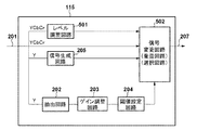
図5は、本実施形態におけるビデオ信号処理部115’の機能構成例を示すブロック図であり、第1の実施形態と同じ構成には同じ参照数字を付し、重複する説明を省略する。本実施形態では、第1の実施形態のビデオ信号処理部115に対してレベル調整回路501が追加されている点で構成が異なるほか、信号変更回路502の動作が異なる。
FIG. 5 is a block diagram illustrating an example of a functional configuration of the video
具体的には、本実施形態の信号変更回路502は、第1の実施形態と同様の強調効果の付与動作に加え、強調効果を付与しない画素値をレベル調整回路501でレベル調整された画素値に置き換える。さらに本実施形態の信号変更回路502は、強調効果を付与する画素の輝度や彩度を、必要に応じてさらに調整する。
Specifically, the
レベル調整回路501は、入力画像の各画素について、輝度および彩度を予め定められた量低減して出力する。低減量は低減を知覚でき、かつ元の画像の視認性を落としすぎない範囲で予め定めておく。また、入力画像全体の平均輝度に基づいて動的に定めてもよい。例えば輝度については0.5EV〜1EVに相当する程度であってよく、彩度については例えば無彩色を0%とした0〜100%で表す場合、0%〜75%の範囲であってよい(0%の場合はグレースケールになる)。ただし、これらは単なる例示であり、他の値とすることも可能である。
The
例えば、動画像(ライブビュー画像、記録中の動画像)のフレームに対して本実施形態を適用してフォーカスアシスト機能を実現した場合、合焦度合いが低い領域については彩度および輝度が低下した状態で表示される。マニュアルまたはオートフォーカス機能により合焦度合いが上昇し、抽出される周波数成分の大きさが所定の条件を満たすと、第1の実施形態と同様に生成された加算信号が適用され、強調効果が付与される。信号変更回路502は、閾値設定回路204からの出力が条件を満たす画素については、レベル調整回路501の出力ではなく、入力された画像信号201を選択し、かつ加算信号を適用(加算)する。
For example, when the focus assist function is realized by applying this embodiment to a frame of a moving image (live view image, moving image being recorded), saturation and luminance are reduced in a region with a low degree of focus. Displayed with status. When the degree of focus is increased by the manual or autofocus function and the size of the extracted frequency component satisfies a predetermined condition, the added signal generated in the same manner as in the first embodiment is applied, and an emphasis effect is given. Is done. The
これにより、合焦度合いが高い画素については、本来の(レベル調整されていない)画素値となる上、さらに加算信号が適用される。したがって、色味の変化(彩度の上昇)と輝度の上昇とが相まって、合焦度合いが低い状態から高い状態に遷移した部分が、陰っていた状態から明るく照らされるような印象を与える強調効果を付与することができる。そのため、別の色をつけたりしなくても、合焦度合いの高い領域が容易に判別可能であり、強調効果によって被写体の視認性が低下するという課題は生じない。 As a result, for pixels with a high degree of focus, the original (not level-adjusted) pixel value is obtained, and an addition signal is further applied. Therefore, a combination of color change (increase in saturation) and increase in luminance, combined with an increase in brightness, gives the impression that the part of the transition from a low focus state to a high state is brightly illuminated from the shadowed state. Can be granted. Therefore, an area with a high degree of focus can be easily discriminated without adding another color, and there is no problem that the visibility of the subject is reduced due to the enhancement effect.
なお、加算信号の適用によって画素の輝度が元の値より上昇することにより、画素の色味が本来の色味より薄くなる。そのため、信号変更回路502において、加算信号の適用後の色味が元の(加算信号の適用前の)色味と視覚的に近づくよう、彩度を元の値よりも高めるように構成してもよい。
In addition, when the luminance of the pixel is increased from the original value by applying the addition signal, the color of the pixel becomes lighter than the original color. Therefore, the
以上説明したように本実施形態によれば、第1の実施形態の構成に加え、強調効果を付与しない画素の輝度や彩度を低下させ、強調効果を付与する画素については輝度や彩度を低下させないようにした。そのため、第1の実施形態による効果に加え、視認性を低下させることなく合焦度合いの高い領域を容易に判別可能な強調効果を付与できるという効果を実現できる。 As described above, according to the present embodiment, in addition to the configuration of the first embodiment, the luminance and saturation of the pixel to which the enhancement effect is not applied are reduced, and the luminance and saturation are applied to the pixel to which the enhancement effect is applied. I tried not to lower it. Therefore, in addition to the effect of the first embodiment, it is possible to realize an effect that an emphasis effect that can easily discriminate an area with a high degree of focus without degrading visibility.
(変形例1)
なお、強調効果を付与しない画素の輝度や彩度を低下させ、強調効果を付与する画素については輝度や彩度を低下させないことによる第2の実施形態の効果は、抽出した高周波成分に基づく加算信号を用いて強調効果を付与する場合においても得られる。
(Modification 1)
It should be noted that the effect of the second embodiment by reducing the luminance and saturation of the pixel to which the enhancement effect is not applied and not reducing the luminance and saturation of the pixel to which the enhancement effect is applied is the addition based on the extracted high frequency component. It can also be obtained when an emphasis effect is applied using a signal.
図4(b)は、抽出した高周波成分に基づく加算信号を用いて強調効果を付与する構成において、第2の実施形態のレベル調整技術を適用した場合のビデオ信号処理部115”のブロック図である。図4(a)および図5と同じ構成については参照数字を共通として説明を省略する。
FIG. 4B is a block diagram of the video
信号変更回路410は、第2の実施形態における信号変更回路502と同様にして対象画素に強調効果を付与するか否かを判定する。そして、強調効果を付与すると判定した場合、信号変更回路410はレベル調整回路501の出力ではなく、入力されたままの画素信号に閾値設定回路404から入力される高周波成分を適用して出力する。また、強調効果を付与しないと判定した場合、信号変更回路410はレベル調整回路501の出力(レベル調整された画素信号)を選択して出力する。
The
このように、加算信号を抽出した高周波成分に基づいて生成する場合においても、合焦度合いが低い画素については輝度や彩度を低減した表示を行い、合焦度合いが高くなった際には加算信号の適用に加えて輝度や彩度を上昇させるように構成できる。それにより、視認性を低下させることなく合焦度合いの高い領域を容易に判別可能な強調効果を付与できるという効果を実現できる。 As described above, even when the addition signal is generated based on the extracted high-frequency component, a pixel with a low focus level is displayed with reduced brightness and saturation, and is added when the focus level is high. In addition to the application of signals, it can be configured to increase brightness and saturation. Thereby, it is possible to realize an effect that an emphasis effect that can easily discriminate a region having a high degree of focus without degrading visibility.
<他の実施形態>
上述の第1および第2の実施形態では、抽出回路で1つの周波数成分を抽出して、強調効果の付与を行うか否かを判定する構成であった。しかし、複数の周波数成分を抽出し、周波数成分ごとに強調効果の付与を行うかどうかを判定するように構成することもできる。
<Other embodiments>
In the first and second embodiments described above, the extraction circuit extracts one frequency component and determines whether or not to give an emphasis effect. However, it is also possible to extract a plurality of frequency components and determine whether to give an emphasis effect for each frequency component.
図6はこのような他の実施形態に係るビデオ信号処理部115の構成例を示しており、図6(a)は第1の実施形態、図6(b)は第2の実施形態に対応している。図6において抽出回路601は、抽出回路202が抽出する周波数成分(第1周波数成分とする)とは異なる周波数成分(第2周波数成分とする)を抽出する。ゲイン調整回路602、閾値設定回路603は、ゲイン調整回路203および閾値設定回路204と同様の構成を有し、第2周波数成分に対するゲイン、およびノイズ低減のための閾値を設定することができる。
FIG. 6 shows a configuration example of the video
信号生成回路205は抽出回路202に対応付けられ、第1周波数成分が条件を満たす画素に対して適用するための加算信号を生成する。また、信号生成回路604は抽出回路601に対応付けられ、第2周波数成分が条件を満たす画素に対して適用するための加算信号を生成する。信号生成回路604は信号生成回路205と同様、元の画素値に応じた加算信号を生成するが、たとえば上述した固定値の値をより低い値に変更するなど、値の異なる加算信号を生成するように構成してもよい。
The
信号変更回路605、605’は、信号変更回路206、502と同様の動作を行うが、抽出された個々の周波数成分の大きさに応じて対象画素に対する強調効果の付与要否について判定するとともに、周波数成分に対応する加算信号を適用させる点で異なる。つまり、抽出する周波数成分ごとに、独立して強調効果を付与することが可能である。
The
例えば、高コントラストの被写体と、低コントラストの被写体とが混在している場合、1つの周波数成分に基づいて強調効果の付与要否を判定すると、低コントラストの被写体に対して強調効果が付与されづらくなる場合が考えられる。しかし、複数の周波数成分を抽出し、個々の周波数成分についての判定基準に基づいて強調効果の付与要否を判定することにより、低コントラストの被写体と、高コントラストの被写体が混在しているシーンにおいても適切に強調効果を付与できる。 For example, when a high-contrast subject and a low-contrast subject are mixed, it is difficult to apply the enhancement effect to a low-contrast subject when it is determined whether or not the enhancement effect needs to be applied based on one frequency component. It may be possible. However, in a scene where both low-contrast subjects and high-contrast subjects are mixed by extracting a plurality of frequency components and determining whether the emphasis effect should be applied based on the determination criteria for each frequency component. Can also give an emphasis effect appropriately.
例えば第1周波数成分が第2周波数成分より高い周波数の成分であるとする。この場合、まず第2周波数成分の大きさが先に条件を満たしたのち、第1周波数成分の大きさが条件を満たすようになる。そのため、まず、第2周波数の大きさに基づく判定によってコントラストの低い被写体および高い被写体について強調効果が付与され、その後、コントラストの高い被写体については第1周波数の大きさに基づく判定による強調効果に切り替わる。そのため、低コントラストの被写体についての合焦度合いについても判別可能となるだけでなく、高コントラストの被写体については合焦度合いが高まるにつれて強調効果が切り替わり、一層精度の高い焦点調節を支援するフォーカスアシスト機能を提供できる。 For example, assume that the first frequency component is a higher frequency component than the second frequency component. In this case, first, the magnitude of the second frequency component first satisfies the condition, and then the magnitude of the first frequency component satisfies the condition. Therefore, first, an enhancement effect is applied to a low-contrast subject and a high-contrast subject by determination based on the magnitude of the second frequency, and thereafter, the high-contrast subject is switched to an enhancement effect based on the determination based on the first frequency magnitude. . Therefore, not only is it possible to determine the degree of focus for low-contrast subjects, but also for high-contrast subjects, the emphasis effect changes as the degree of focus increases, and a focus assist function that supports more precise focus adjustment Can provide.
なお、図6(b)の構成(第2の実施形態に対応)において、信号変更回路605’は、レベル調整回路501の出力を選択するかどうかについても、個々の周波数成分の大きさに応じて判定する。
In the configuration of FIG. 6B (corresponding to the second embodiment), whether the
(その他の実施形態)
本発明をその例示的な実施形態に基づいて詳述してきたが、本発明はこれら特定の実施形態に限られるものではなく、特許請求の範囲に記載された範囲内で様々な変更を行うことが可能である。また、レベル調整を行う実施形態と行わない実施形態とを切り替え可能に構成したり、加算信号を実施形態にしたがって生成する構成と抽出した周波数成分から生成する構成とを切り替え可能に構成してもよい。
(Other embodiments)
Although the invention has been described in detail on the basis of exemplary embodiments thereof, the invention is not limited to these specific embodiments, and various modifications can be made within the scope described in the claims. Is possible. In addition, the embodiment in which the level adjustment is performed and the embodiment in which the level adjustment is not performed can be switched, or the configuration in which the addition signal is generated according to the embodiment and the configuration in which the addition signal is generated from the extracted frequency component can be switched. Good.
例えば、上述した実施形態に係る強調効果の付与動作を、フォーカスアシスト機能以外に適用することもできる。例えば、記録済みの動画像や静止画像に適用して合焦領域を明示するために用いてもよい。また、ライトフィールドカメラで撮影した画像データのように、撮影後に合焦領域を変更可能な画像データに適用してもよい。この場合、仮想結像面が変更される都度、再構成される静止画像(リフォーカス画像)について実施形態に係る強調効果の付与動作を適用することで、所望の被写体に合焦したリフォーカス画像の取得を支援することができる。 For example, the emphasis effect imparting operation according to the above-described embodiment can be applied to a function other than the focus assist function. For example, it may be used to clearly indicate a focus area by applying it to a recorded moving image or still image. Further, the present invention may be applied to image data whose focus area can be changed after shooting, such as image data shot with a light field camera. In this case, each time the virtual imaging plane is changed, the refocused image focused on the desired subject is applied to the reconstructed still image (refocused image) by applying the enhancement effect applying operation according to the embodiment. Can help you get.
本発明は、上述の実施形態の1以上の機能を実現するプログラムを、ネットワーク又は記憶媒体を介してシステム又は装置に供給し、そのシステム又は装置のコンピュータにおける1つ以上のプロセッサーがプログラムを読出し実行する処理でも実現可能である。また、1以上の機能を実現する回路(例えば、ASIC)によっても実現可能である。 The present invention supplies a program that realizes one or more functions of the above-described embodiments to a system or apparatus via a network or a storage medium, and one or more processors in a computer of the system or apparatus read and execute the program This process can be realized. It can also be realized by a circuit (for example, ASIC) that realizes one or more functions.
例えば、上述の実施形態に係るビデオ信号処理部115をCPU、MPU、ソフトウェア的に動的再構成可能なプロセッサ(以下、代表してCPUという)で構成することができる。この場合、CPUは、不揮発性記憶装置に記憶されたプログラムをRAMにロードして実行することにより、図7のフローチャートに示すように動作することができる。なお、図7において、点線で記載された工程は第2の実施形態およびその変形例で実行される工程を示している。
For example, the video
S101でCPUは、処理対象の画像全体(1フレーム)をメモリに読み込み、画素ごとに以下の処理を実行する。S103、S105、S201は実質的に並列に処理される工程である。S103でCPUは周波数成分の抽出処理を行う。このステップは、周波数成分の抽出、ゲインの適用、ノイズ低減を含み、回路202〜204、402〜404、601〜603の動作に相当する。
In S101, the CPU reads the entire image to be processed (one frame) into the memory and executes the following processing for each pixel. S103, S105, and S201 are processes that are processed substantially in parallel. In S103, the CPU performs frequency component extraction processing. This step includes extraction of frequency components, application of gain, and noise reduction, and corresponds to the operation of the
S105でCPUは、処理対象画素の値に応じた加算信号を生成する。この動作は、信号生成回路205や604の動作に相当する。また、レベル調整を利用する実施形態を実現する場合、S201でCPUは処理対象画素の輝度および彩度の低減処理を実行する。この処理はレベル調整回路501の動作に相当する。
In S105, the CPU generates an addition signal corresponding to the value of the processing target pixel. This operation corresponds to the operation of the
S107でCPUは、周波数成分の抽出処理で得られた値の大きさが、予め定められた条件(例えば閾値を超えている)を満たすか否かの判定により、処理対象画素に強調効果を付与するかどうかを判定する。例えば予め定められた条件を満たさず、強調効果を付与しないと判定した場合、CPUは必要に応じてS207を実行した後、S111に処理を進める。S207はレベル調整を利用する実施形態において実行され、CPUは処理対象の画素をレベル調整処理後の画素に置換して出力する(あるいは処理後の画素としてレベル調整後の画素を選択する)。 In S107, the CPU gives an enhancement effect to the processing target pixel by determining whether or not the magnitude of the value obtained by the frequency component extraction processing satisfies a predetermined condition (for example, exceeds a threshold). Determine whether to do. For example, when it is determined that the predetermined condition is not satisfied and the emphasis effect is not given, the CPU executes S207 as necessary, and then proceeds to S111. S207 is executed in the embodiment using the level adjustment, and the CPU replaces the pixel to be processed with the pixel after the level adjustment processing (or selects the pixel after the level adjustment as the pixel after the processing).
一方、例えば予め定められた条件を満たし、強調効果を付与する判定した場合、CPUは必要に応じてS203を実行した後、S109に処理を進める。S203はレベル調整を利用する実施形態において実行され、CPUは処理対象の画素をそのまま出力する(あるいは処理後の画素としてレベル調整されていない画素を選択する)。 On the other hand, for example, when it is determined that a predetermined condition is satisfied and an emphasis effect is applied, the CPU proceeds to S109 after executing S203 as necessary. S203 is executed in an embodiment using level adjustment, and the CPU outputs the pixel to be processed as it is (or selects a pixel that has not been level-adjusted as a pixel after processing).
S109でCPUは、S105で生成した加算信号を処理対象画素に適用する。具体的には、CPUは、処理対象画素の輝度成分にS105で算出した値を加算する。その後、CPUは必要に応じてS205を実行した後、S111に処理を進める。S205はレベル調整を利用する実施形態において必要に応じて実行され、加算信号の適用により元の色味と変化した場合に、元の色味と同等に知覚されるように処理対象画素の彩度を上昇させる。 In S109, the CPU applies the addition signal generated in S105 to the processing target pixel. Specifically, the CPU adds the value calculated in S105 to the luminance component of the processing target pixel. Thereafter, the CPU executes S205 as necessary, and then proceeds to S111. S205 is executed as necessary in the embodiment using the level adjustment, and when the original color is changed by applying the addition signal, the saturation of the processing target pixel is perceived to be equivalent to the original color. To raise.
S111でCPUは、1画面分の全画素について処理を適用したかどうか判定し、未処理の画素があればS103〜S201へ、未処理の画素がなければ、1画面分の処理を終了する。動画像に対しては、例えばフレームごとに同様の処理を繰り返す。 In S111, the CPU determines whether or not the process has been applied to all pixels for one screen. If there is an unprocessed pixel, the process proceeds to S103 to S201, and if there is no unprocessed pixel, the process for one screen is terminated. For a moving image, for example, the same processing is repeated for each frame.
115…ビデオ信号処理部、202…抽出回路、203…ゲイン調整回路、204…閾値設定回路、205…信号生成回路、206…信号変更回路、501…レベル調整回路
DESCRIPTION OF
Claims (13)
前記画像信号の処理対象画素に強調効果を付与するための信号を生成する生成手段と、
前記処理対象画素の輝度および彩度を低減する調整手段と、
前記抽出手段が抽出した前記周波数成分の大きさに基づく判定に応じて、前記生成手段が生成した前記信号を前記処理対象画素に適用して出力する適用手段と、
を有し、
前記生成手段は、予め定められた固定値と前記処理対象画素の値との差に基づき、前記処理対象画素の値の増加に連れて連続的または段階的に減少する値を有するように前記信号を生成し、
前記適用手段は、前記調整手段によって輝度及び彩度が低減されていない前記処理対象画素に前記信号を適用して出力し、前記処理対象画素に前記信号を適用しない場合には前記調整手段によって輝度及び彩度が低減された前記処理対象画素を出力することを特徴とする画像処理装置。 Extracting means for extracting a predetermined frequency component from the image signal;
Generating means for generating a signal for imparting an enhancement effect to the processing target pixel of the image signal;
Adjusting means for reducing the luminance and saturation of the pixel to be processed;
Applying means for applying and outputting the signal generated by the generating means to the processing target pixel in response to the determination based on the size of the frequency component extracted by the extracting means;
Have
The generating means has the value that continuously or stepwise decreases as the value of the processing target pixel increases based on a difference between a predetermined fixed value and the value of the processing target pixel. Produces
The applying unit applies and outputs the signal to the processing target pixel whose luminance and saturation are not reduced by the adjusting unit, and when the signal is not applied to the processing target pixel, the adjusting unit performs luminance. And an image processing apparatus that outputs the processing target pixel with reduced saturation.
前記抽出手段はそれぞれ異なる周波数成分を抽出し、
前記生成手段はそれぞれ異なる前記抽出手段に対応付けられ、
前記適用手段は、前記抽出手段のそれぞれが抽出した前記周波数成分の大きさに基づく判定に応じて、前記生成手段のそれぞれが生成した前記信号を前記処理対象画素に適用して出力する、ことを特徴とする請求項1から請求項5のいずれか1項に記載の画像処理装置。 The extraction means and the generation means are plural,
The extraction means extracts different frequency components,
The generation means is associated with different extraction means,
The applying unit applies the signal generated by each of the generating units to the processing target pixel according to the determination based on the magnitude of the frequency component extracted by each of the extracting units, and outputs the applied signal. the image processing apparatus according to any one of claims 1 to 5, wherein.
前記撮像素子で撮像された動画像を連続的に表示する表示手段と、
請求項1から請求項8のいずれか1項に記載の画像処理装置と、を有し、
前記画像処理装置の前記抽出手段が、前記表示手段に表示する動画像の信号を対象として前記抽出を行い、
前記画像処理装置の前記適用手段の出力を、前記表示手段に表示することを特徴とする撮像装置。 An image sensor;
Display means for continuously displaying moving images captured by the image sensor;
An image processing apparatus according to any one of claims 1 to 8 ,
The extraction unit of the image processing apparatus performs the extraction on a moving image signal to be displayed on the display unit;
An imaging apparatus, wherein the output of the application means of the image processing apparatus is displayed on the display means.
画像信号から予め定められた周波数成分を抽出し、
前記画像信号の処理対象画素に強調効果を付与するための信号を、予め定められた固定値と前記処理対象画素の値との差に基づき、前記処理対象画素の値の増加に連れて連続的または段階的に減少する値を有するように生成し、
前記抽出された前記周波数成分の大きさに基づく判定に応じて、輝度及び彩度が低減されていない前記処理対象画素に前記信号を適用して出力するか、輝度及び彩度が低減された前記処理対象画素に前記信号を適用せずに出力する、ことを特徴とする画像処理方法。 An image processing method executed by an image processing apparatus,
Extract a predetermined frequency component from the image signal,
Based on the difference between a predetermined fixed value and the value of the processing target pixel, a signal for giving an enhancement effect to the processing target pixel of the image signal is continuously increased as the value of the processing target pixel increases. Or to have a step-down value ,
Depending on the determination based on the size of the extracted frequency component, the signal is applied to the pixel to be processed whose luminance and saturation are not reduced, or is output, or the luminance and saturation are reduced. An image processing method, wherein the signal is output without applying the signal to a processing target pixel.
Priority Applications (4)
| Application Number | Priority Date | Filing Date | Title |
|---|---|---|---|
| JP2015152696A JP6592293B2 (en) | 2015-07-31 | 2015-07-31 | Image processing apparatus, image processing method, and imaging apparatus |
| EP16177932.7A EP3125523A1 (en) | 2015-07-31 | 2016-07-05 | Image processing apparatus, image processing method and image capture apparatus |
| US15/217,505 US9979943B2 (en) | 2015-07-31 | 2016-07-22 | Image processing apparatus for applying emphasis effect processing to a specific component of an image signal, image processing method and image capture apparatus |
| CN201610620716.0A CN106412391B (en) | 2015-07-31 | 2016-07-29 | Image processing apparatus, image processing method, and image capturing apparatus |
Applications Claiming Priority (1)
| Application Number | Priority Date | Filing Date | Title |
|---|---|---|---|
| JP2015152696A JP6592293B2 (en) | 2015-07-31 | 2015-07-31 | Image processing apparatus, image processing method, and imaging apparatus |
Publications (3)
| Publication Number | Publication Date |
|---|---|
| JP2017034481A JP2017034481A (en) | 2017-02-09 |
| JP2017034481A5 JP2017034481A5 (en) | 2018-09-06 |
| JP6592293B2 true JP6592293B2 (en) | 2019-10-16 |
Family
ID=57988992
Family Applications (1)
| Application Number | Title | Priority Date | Filing Date |
|---|---|---|---|
| JP2015152696A Active JP6592293B2 (en) | 2015-07-31 | 2015-07-31 | Image processing apparatus, image processing method, and imaging apparatus |
Country Status (1)
| Country | Link |
|---|---|
| JP (1) | JP6592293B2 (en) |
Families Citing this family (1)
| Publication number | Priority date | Publication date | Assignee | Title |
|---|---|---|---|---|
| JP7420141B2 (en) * | 2019-07-17 | 2024-01-23 | ソニーグループ株式会社 | Image processing device, imaging device, image processing method, program |
-
2015
- 2015-07-31 JP JP2015152696A patent/JP6592293B2/en active Active
Also Published As
| Publication number | Publication date |
|---|---|
| JP2017034481A (en) | 2017-02-09 |
Similar Documents
| Publication | Publication Date | Title |
|---|---|---|
| JP5321163B2 (en) | Imaging apparatus and imaging method | |
| JP5187241B2 (en) | Imaging apparatus and imaging method | |
| JP6317577B2 (en) | Video signal processing apparatus and control method thereof | |
| JP5123137B2 (en) | Imaging apparatus and imaging method | |
| US20110187900A1 (en) | Digital image processing apparatus, an image processing method, and a recording medium storing the image processing method | |
| JP5873380B2 (en) | Image processing apparatus and control method thereof | |
| JP2017022610A (en) | Image processing apparatus and image processing method | |
| JP4999871B2 (en) | Imaging apparatus and control method thereof | |
| US9979943B2 (en) | Image processing apparatus for applying emphasis effect processing to a specific component of an image signal, image processing method and image capture apparatus | |
| US20180365802A1 (en) | Image processing apparatus, image processing method, and non-transitory computer-readable recording medium | |
| JP6032912B2 (en) | Imaging apparatus, control method thereof, and program | |
| US9282257B2 (en) | Image apparatus and imaging method | |
| JP5948997B2 (en) | Imaging apparatus and imaging method | |
| JP2015211233A (en) | Image processing apparatus and control method for image processing apparatus | |
| JP5146015B2 (en) | Imaging apparatus and imaging method | |
| JP6592293B2 (en) | Image processing apparatus, image processing method, and imaging apparatus | |
| JP5335964B2 (en) | Imaging apparatus and control method thereof | |
| WO2014175273A1 (en) | Image capture device and control method thereof | |
| JP5310331B2 (en) | Imaging apparatus and imaging method | |
| JP6592292B2 (en) | Image processing apparatus, image processing method, and imaging apparatus | |
| JP2020036162A (en) | Image processing device, imaging device, image processing method, and program | |
| JP2007019593A (en) | Contour emphasizing signal generating circuit, image signal processing apparatus, imaging apparatus, contour emphasizing signal generating method, and program | |
| JP2010243923A (en) | Imaging apparatus and method of controlling the same | |
| JP5091734B2 (en) | Imaging apparatus and imaging method | |
| JP5169540B2 (en) | Imaging apparatus and imaging method |
Legal Events
| Date | Code | Title | Description |
|---|---|---|---|
| A521 | Request for written amendment filed |
Free format text: JAPANESE INTERMEDIATE CODE: A523 Effective date: 20180725 |
|
| A621 | Written request for application examination |
Free format text: JAPANESE INTERMEDIATE CODE: A621 Effective date: 20180725 |
|
| A977 | Report on retrieval |
Free format text: JAPANESE INTERMEDIATE CODE: A971007 Effective date: 20190422 |
|
| A131 | Notification of reasons for refusal |
Free format text: JAPANESE INTERMEDIATE CODE: A131 Effective date: 20190510 |
|
| A521 | Request for written amendment filed |
Free format text: JAPANESE INTERMEDIATE CODE: A523 Effective date: 20190701 |
|
| TRDD | Decision of grant or rejection written | ||
| A01 | Written decision to grant a patent or to grant a registration (utility model) |
Free format text: JAPANESE INTERMEDIATE CODE: A01 Effective date: 20190823 |
|
| A61 | First payment of annual fees (during grant procedure) |
Free format text: JAPANESE INTERMEDIATE CODE: A61 Effective date: 20190920 |
|
| R151 | Written notification of patent or utility model registration |
Ref document number: 6592293 Country of ref document: JP Free format text: JAPANESE INTERMEDIATE CODE: R151 |