JP4663684B2 - AC motor control device and control method - Google Patents
AC motor control device and control method Download PDFInfo
- Publication number
- JP4663684B2 JP4663684B2 JP2007147609A JP2007147609A JP4663684B2 JP 4663684 B2 JP4663684 B2 JP 4663684B2 JP 2007147609 A JP2007147609 A JP 2007147609A JP 2007147609 A JP2007147609 A JP 2007147609A JP 4663684 B2 JP4663684 B2 JP 4663684B2
- Authority
- JP
- Japan
- Prior art keywords
- current
- motor
- inverter
- phase
- voltage
- Prior art date
- Legal status (The legal status is an assumption and is not a legal conclusion. Google has not performed a legal analysis and makes no representation as to the accuracy of the status listed.)
- Expired - Lifetime
Links
Images


Description
本発明は、交流電動機の制御装置及び制御方法に関するものである。 The present invention relates to an AC motor control device and control method.
従来、交流電動機の回転速度センサあるいは位置センサを用いない方式としては、電動機の相電流を検出し、磁極位置の推定演算を行う制御装置が知られている(例えば、引用特許文献1参照)。 Conventionally, as a method that does not use a rotational speed sensor or a position sensor of an AC motor, a control device that detects a phase current of the motor and performs an estimation calculation of a magnetic pole position is known (see, for example, Patent Document 1).
また電流センサを用いない方式として、電動機を駆動するインバータの直流電流を検出し、その瞬時値とインバータのスイッチング状態から、電動機の交流電流を再現する電流再現方式が提案されている(例えば、引用特許文献2参照)。本方式は、インバータを駆動するゲートパルス信号を利用し、インバータの直流電流に瞬間的に現れる電動機電流をサンプル・ホールドし、電動機電流を間接的に検出している。 Further, as a method not using a current sensor, a current reproduction method has been proposed in which a direct current of an inverter that drives an electric motor is detected, and an alternating current of the electric motor is reproduced from the instantaneous value and the switching state of the inverter (for example, cited) Patent Document 2). This system uses a gate pulse signal for driving an inverter, samples and holds the motor current that appears instantaneously in the DC current of the inverter, and indirectly detects the motor current.
しかしながら電流再現方式は、インバータの直流電流とゲートパルス信号から電動機電流を再現しているため、極端にゲートパルスが短い場合に、電動機電流成分を捕らえることが難しくなる。特に、インバータの平均スイッチング周波数(キャリア周波数)を高く設定するほど、ゲートパルスが短くなり、電流の再現が難しい。インバータのキャリア周波数を下げた対策を行えば、電流高調波の増大化による効率の低下や、電磁ノイズ発生の原因となる。また、インバータのキャリア周期内で最低2回の電流サンプリングを行う必要があり、特別な回路を必要とする。しかも、ワンチップ・マイコンで実現するには2個のアナログ入力端子が必須であり、マイコン内にAD変換器を2組用意するか、高速AD変換器を1個備えて連続して電流を読み込む必要がある。 However, since the current reproduction method reproduces the motor current from the DC current of the inverter and the gate pulse signal, it becomes difficult to capture the motor current component when the gate pulse is extremely short. In particular, the higher the average switching frequency (carrier frequency) of the inverter, the shorter the gate pulse, and the more difficult it is to reproduce the current. If measures are taken to reduce the carrier frequency of the inverter, the efficiency may decrease due to an increase in current harmonics and electromagnetic noise may be generated. Further, it is necessary to perform current sampling at least twice within the carrier period of the inverter, and a special circuit is required. Moreover, two analog input terminals are indispensable to realize with a one-chip microcomputer, and two sets of AD converters are prepared in the microcomputer, or one high-speed AD converter is provided and current is continuously read. There is a need.
本発明は、シンプルな制御構成で、且つ、高いキャリア周波数での高性能な電動機駆動を実現する制御装置及び制御方法を提供する。 The present invention provides a control device and a control method that realize a high-performance motor drive with a simple control configuration and a high carrier frequency.
上記課題を解決するため、例えば特許請求の範囲に記載されるよう構成すればよい。In order to solve the above-mentioned problem, for example, it may be configured as described in the claims.
本発明によれば、交流電動機の回転子位置を検出する位置センサと、電流を検出する電流センサを用いることなく、シンプルな制御構成で、尚且つ、高いキャリア周波数での高性能な交流電動機の制御装置が実現できる。 According to the present invention, a high-performance AC motor with a simple control configuration and a high carrier frequency can be used without using a position sensor that detects the rotor position of the AC motor and a current sensor that detects current. A control device can be realized.
次に、図1ないし図17を参照して、本発明による交流電動機を制御する制御装置の実施例について説明する。尚、以下の実施形態では、交流電動機として、永久磁石型同期電動機を用いて説明するが、誘導電動機やリラクタンスモータなどの他の交流電動機に関しても、同様に実現可能である。 Next, an embodiment of a control device for controlling an AC motor according to the present invention will be described with reference to FIGS. In the following embodiments, a permanent magnet synchronous motor will be described as an AC motor. However, other AC motors such as an induction motor and a reluctance motor can be similarly realized.
(実施例1)
図1は、本発明による交流電動機制御装置の実施例1の系統構成を示すブロック図である。本実施例の制御装置は、電動機に回転数指令ωr *を与える回転数指令発生器1と、電動機の交流印加電圧を演算し、パルス幅変調信号(PWM信号)に変換して出力する制御器2と、このPWM信号により駆動されるインバータ3と、インバータ3に電力を供給する直流電源4と、制御対象である永久磁石型の電動機5と、直流電源4がインバータ3へ供給する電流I0 を検出する電流検出器6からなる。
Example 1
FIG. 1 is a block diagram showing a system configuration of
制御器2は、電動機5の極数Pを用いて回転数指令ωr *を電動機5の電気角周波数指令ω1 *に変換する変換ゲイン7と、制御装置内部の交流位相θdcを演算する積分器8と、電流I0 の検出値をサンプリングする電流サンプラー9と、サンプリングされた電流値I0sに対して、指令を与えるI0s * 発生器10と、信号を加算する加算器11と、サンプルされた電流I0sが、I0s * に一致するように電動機5への印加電圧指令を演算する電流制御器12と、印加電圧指令に基づいて、電動機5への交流電圧を演算するdq逆変換器13と、交流電圧指令に基づいて、インバータ3を駆動するゲートパルスを作成するPWM発生器14と、からなる。
The
インバータ3は、インバータの主回路部31と、主回路へのゲート信号を発生するゲート・ドライバ32からなり、インバータ3に電力を供給する直流電源4は、交流電源41と、交流を整流するダイオード・ブリッジ42と、直流電源に含まれる脈動成分を抑制する平滑コンデンサ43とで構成されている。
The inverter 3 includes a main circuit unit 31 of the inverter and a
次に、図1を用いて、本実施例1の動作原理を説明する。変換ゲイン7は、回転数指令発生器1からの回転数指令ωr *に基づき、電動機5の電気角周波数ω1 *を演算し出力する。さらに積分器8を用いてω1 *を積分し、交流位相θdcを演算する。電流サンプラー9では、インバータ3の直流電流I0 をサンプル・ホールドし、I0sとして値を取り込む。I0sは、I0s * 発生器10が出力する電流指令I0s * に一致するように、電流制御器12により制御される。dq逆変換器13では、電流制御器12の出力である印加電圧指令Vqc * と、Vdc * に基づき、交流電圧指令vu*〜vw*を演算する。なお本実施例ではVdc * を0とした。dq逆変換器13の演算式は、数1のようになる。
Next, the operation principle of the first embodiment will be described with reference to FIG. The

次に、PWM発生器14において、交流電圧指令をPWM信号に変換する。ゲート・ドライバ32は、このPWM信号に基づいてスイッチング素子を駆動し、電動機5に対してVdc *,Vqc *に相当する交流電圧を印加する。
Next, the
図2、および図3は、PWM発生器14において、交流電圧指令から、ゲートパルスを作成する様子を示した波形である。ゲートパルスは、図のように、搬送波信号の三角波キャリアと、交流電圧指令の大きさを比較することで作成される。ここで交流電圧指令は図2(a)のように、vu*>vv*>vw* であり、且つ、|vw*|>|vu*|>|vv*| の条件である。この時のゲートパルスGPu〜GPwは、図2(b)のようになる。同図において、GPu〜GPwは、それぞれ値が「1」の場合には、インバータの主回路部31における上側の素子(Sup,Svp,Swp)がオンし、「0」の場合には、下側の素子(Sun,Svn,Swn)がオンすることを意味する。図2の条件において、電流検出器6に現れるインバータの直流電流I0 は、図2(c)のような波形になる。すなわち、I0 は、断続したパルス状の電流波形になり、それぞれに二つの相電流が瞬時的に現れ、図2においては、W相とU相の電流が観測できる。これら観測できる2つの相電流は、電圧最大相の電流と、電圧最小相の電流である。さらに、これら2つの相電流のうち、電圧指令の絶対値の大きな方の通電期間が長くなる。ここで、電圧最大相はU相、電圧最小相はW相であり、絶対値の大きな相はW相となる。
2 and 3 are waveforms showing how the
つまり、断続電流であるI0 の通流期間内、しかも通電期間の中間点近傍で電流をサンプリングすると、電圧指令の絶対値が最も大きな相の電流が検出できることになる。なお、三相の本実施例においては、インバータ電流の立ち上り時刻から通電期間の33〜67%の範囲内であれば、中間点近傍でのサンプリングと同様の効果が得られる。 That is, if the current is sampled within the conduction period of I 0 , which is the intermittent current, and in the vicinity of the midpoint of the energization period, the current of the phase having the largest absolute value of the voltage command can be detected. In the three-phase embodiment, the same effect as the sampling in the vicinity of the intermediate point can be obtained as long as it is within the range of 33 to 67% of the energization period from the rise time of the inverter current.
図3は、図2とは条件が異なり、vu*>vv*>vw*であり、且つ、|vu*|>|vw*|>|vv*|となる条件である。この場合は、I0 の通電期間の中間点近傍で電流をサンプリングすると、U相の電流値が検出できることになる。 FIG. 3 is different from FIG. 2 in that vu * > vv * > vw * and | vu * |> | vw * |> | vv * |. In this case, the U-phase current value can be detected by sampling the current near the midpoint of the I 0 energization period.
ここで、交流電圧指令を数2のように定義する。
Here, the AC voltage command is defined as in
この場合、電圧指令波形は、図4(a)のようになる。I0 の通電期間の中間点近傍でサンプリングを行うと、電圧位相θv に応じて、検出できる相電流が、図4(b)のように60度毎に変化する。サンプリング後の電流波形であるI0sは、同図(c)の太線のような波形になる。 In this case, the voltage command waveform is as shown in FIG. When sampling is performed near the midpoint of the I 0 energization period, the detectable phase current changes every 60 degrees as shown in FIG. 4B in accordance with the voltage phase θ v . The current waveform I 0s after sampling has a waveform like the thick line in FIG.
交流電動機は、インダクタンス成分を持つため、電流は電圧に対して遅れ位相となる。よって、図4の(a)と(c)のような関係になる。電流位相は、電動機定数や、負荷条件などによって変化するが、ほぼ、電流の最大付近を含むような波形を観測できる。 Since the AC motor has an inductance component, the current is delayed in phase with respect to the voltage. Therefore, the relationship shown in FIGS. 4A and 4C is obtained. Although the current phase varies depending on the motor constant, the load condition, etc., a waveform including almost the maximum current can be observed.
本実施例では、I0sを、電流指令I0s * に一致するように電流制御を行う。この結果、電動機5には、所定量の交流電流が流れることになる。電流が十分流れることで、起動時などのトルクを確保することが可能である。 In this embodiment, the I 0 s, performs the current control to match the current command I 0 s *. As a result, a predetermined amount of alternating current flows through the electric motor 5. By sufficiently flowing the current, it is possible to ensure a torque at the time of starting.
従来の「電流再現方式」では、電動機の起動時には、三角波キャリアの周波数が高いほどゲートパルス幅が狭くなり、電流検出そのものが難しくなる。また、起動時には、デッドタイム(インバータの上下スイッチング素子の短絡防止期間)の影響や、スイッチング素子のオン電圧降下の影響などで、フィードバックなしで所定量の電流を流すことは困難である。しかしながら、本実施例では、通流パルス幅の中間時点近傍で電流をサンプルし、その値を制御することで、起動に必要なだけの電流を確実に流すことができる。また、電流サンプルのタイミングは単純であり、複雑な電流検出アルゴリズムを必要としない。よって、マイコンを用いて本実施例を実現するためには、電流検出器6の出力を、1つのアナログ入力端子に接続すればよく、また、図示しないAD変換器も1個備えていればよい。 In the conventional “current reproduction method”, when the motor is started, the higher the frequency of the triangular wave carrier, the narrower the gate pulse width, and the current detection itself becomes difficult. At the time of start-up, it is difficult to flow a predetermined amount of current without feedback due to the influence of dead time (short-circuit prevention period of the upper and lower switching elements of the inverter) and the on-voltage drop of the switching elements. However, in this embodiment, the current is sampled in the vicinity of the intermediate time point of the conduction pulse width and the value is controlled, so that the current necessary for starting can be surely passed. Also, current sample timing is simple and does not require complex current detection algorithms. Therefore, in order to realize the present embodiment using a microcomputer, the output of the current detector 6 may be connected to one analog input terminal, and one AD converter (not shown) may be provided. .
次に、I0 をサンプル・ホールドするタイミングの発生方法について説明する。 Next, a method of generating timing for sampling and holding I 0 will be described.
I0 の通電期間の中間時点近傍で電流をサンプリングするためには、例えば、I0 の立ち上がり、ならびに立ち下がりをトリガとして、パルス幅を計測しておき、次回のパルスの立ち上りから、パルスの中間時点を推定して、サンプル信号を発生させることで実現できる。しかし、この方法では、ハードウエアが複雑となるし、また、ノイズなどの影響による誤動作も懸念される。 In order to sample the current in the vicinity of the middle point of the energization period of I 0 , for example, the pulse width is measured using the rising edge and falling edge of I 0 as a trigger, and the middle of the pulse from the rising edge of the next pulse. This can be realized by estimating the time point and generating a sample signal. However, with this method, the hardware is complicated, and there is a concern about malfunction due to the influence of noise or the like.
図5を用いて、サンプル信号の発生方法について説明する。図2ならびに図3に示したPWM発生方法の場合、通電期間の中間時刻は、三角波キャリアの上下ピークの中間時点に一致する。すなわち、三角波キャリアの零クロスをトリガとして、I0 のサンプル信号を発生させれば、簡単にI0sを取り込むことが可能になる。 A method for generating a sample signal will be described with reference to FIG. In the PWM generation method shown in FIGS. 2 and 3, the intermediate time of the energization period coincides with the intermediate time of the upper and lower peaks of the triangular wave carrier. That is, if a sample signal of I 0 is generated using a zero cross of a triangular wave carrier as a trigger, I 0s can be easily captured.
また、PWM方式によっては、図6に示すような電圧指令波形を用いる場合がある。これらは、「二相スイッチング方式」等と呼ばれているPWM変調方式であり、三相のいずれか1相がスイッチング動作を行わないものである。例えば、図6において、60度<θv <120度の期間では、U相のスイッチング素子は上側(図1のSup)がオンし続け、下側(図1のSun)はオフ状態を保つ。この電圧指令は、元の正弦波状の電圧指令に対して、三相すべてに共通の電圧成分(零相成分)を加えることで実現できる。 Depending on the PWM method, a voltage command waveform as shown in FIG. 6 may be used. These are PWM modulation methods called “two-phase switching method”, and one of the three phases does not perform a switching operation. For example, in FIG. 6, in the period of 60 degrees <θ v <120 degrees, the U-phase switching element keeps the upper side (S up in FIG. 1) turned on and the lower side (S un in FIG. 1) shows the off state. keep. This voltage command can be realized by adding a common voltage component (zero phase component) to all three phases to the original sinusoidal voltage command.
この条件での、電圧指令,ゲートパルス、ならびにI0 を、図7に示す。 FIG. 7 shows the voltage command, gate pulse, and I 0 under these conditions.
図7からわかるように、U相電圧が三角波キャリアの上側ピークよりも大きい時には、三角波キャリアの上側ピーク時が、通流期間の中間時刻になる。よって、このタイミングで、電流サンプルを実施すればよいことになる。尚、一つの相の電圧指令を、例えば図7の0〜60度期間のような負側に飽和させる場合には、三角波キャリアの下側ピーク時点で電流をサンプルすればよいことになる。 As can be seen from FIG. 7, when the U-phase voltage is larger than the upper peak of the triangular wave carrier, the upper peak time of the triangular wave carrier is the intermediate time of the current passing period. Therefore, the current sampling may be performed at this timing. Note that when the voltage command of one phase is saturated to the negative side, for example, in the period of 0 to 60 degrees in FIG. 7, the current may be sampled at the lower peak time of the triangular wave carrier.
(実施例2)
次に、図8を用いて、本発明による実施例2について説明する。
(Example 2)
Next,
実施例1では、電動機に流れる電流を所定値になるように流し、駆動に必要な電流を確保するものであった。それに対し、実施例2では、電動機に流れる「有効電流」を検出して、電動機を高性能に制御することを目的としている。 In the first embodiment, the current flowing through the electric motor is caused to flow to a predetermined value, and the current necessary for driving is ensured. On the other hand, the second embodiment aims to detect the “effective current” flowing through the motor and control the motor with high performance.
図8は、制御器2Aのブロック構成を示すものであり、図1における制御器2の代わりに、図8の制御器2Aを用いることで、実施例2が実現できる。図8においては、I0sに対するフィルタ15と、フィルタ15の出力に基づいて、電動機の電気角周波数指令ω1 *にΔω1 を加えるω1 補償器16と、ω1 *から、電動機への印加電圧を決定する電圧指令演算器17が、図1の制御器2と異なるブロックである。
FIG. 8 shows a block configuration of the
制御器2Aでは電流制御を行わず、電圧指令演算器17を用いて、ω1 *から直接電圧指令Vqc * を演算している。このように、電動機制御方式としては、V/F一定制御を基本としているが、図1の制御器のように、電流制御を用いても問題はない。
The
次に、本実施例の特徴部分であるフィルタ15、ならびにω1 補償器16について説明する。図8の制御器2Aでは、I0sに対して、フィルタ15を設けており、このフィルタ出力を有効電流Ia としている。I0sにフィルタ15を介することで、有効電流Ia が得られる原理を、以下に示す。
Next, the
電動機への印加電圧V、ならびに電流Iを、数3のように定義する。なお電圧Vをu相電圧、電流Iをu相電流とする。 The applied voltage V to the motor and the current I are defined as in Equation 3. The voltage V is a u-phase voltage and the current I is a u-phase current.
数3において、V0 は電圧振幅であって本実施例ではVqc * に一致、I0 は電流振幅、θv は電圧位相、δは電流位相(力率角)である。ここで、数3のIは、数4のように表すことができる。
In Equation 3, V 0 is a voltage amplitude, and in this embodiment, coincides with V qc * , I 0 is a current amplitude, θ v is a voltage phase, and δ is a current phase (power factor angle). Here, I in Equation 3 can be expressed as in
数4から、有効電流、ならびに無効電流の大きさIa ,Ir は、数5のように表される。
From
数4は、u相電流であるので、60度<θv <120度の期間において、I0sとして観測される。フィルタ15により、この期間の電流が平均化されるものとし、数4のこの間の平均値Im を求めてみる。60度〜120度期間の平均値であるので、
Since
となる。すなわち、有効電流成分Ia は、平均値Im を用いることで、 It becomes. That is, the effective current component I a, by using the average value I m,
として演算することが可能になる。よって、フィルタ15を介してI0sを平均化することで、有効電流Ia を検出することができる。
Can be calculated as Therefore, the effective current I a can be detected by averaging I 0s through the
有効電流Ia は、電動機の負荷の大きさを直接示すものであるため、制御に有効に使うことで、より安定な電動機の制御装置が実現できる。図8に示す制御器2Aでは、Ia に基づいてω1 *への補償量であるΔω1 を演算している。ω1 補償器16は、Ia に対して不完全微分を実施し、負荷が増えて有効電流が増加した時には、電気角周波数を下げ、逆に負荷が減少した場合には電気角周波数を上げるように動作している。これによって、負荷変動による過渡振動を大幅に低減することが可能になり、より安定な交流電動機の制御装置が実現できる。
Active current I a, since it indicates the magnitude of the load of the motor directly, by effectively used to control the control device of a more stable motor can be realized. In the
尚、フィルタ15は、電動機を駆動する周波数の6倍の高調波成分を取り除く必要がある。この場合、1次遅れフィルタなどを介するよりも、むしろ移動平均を用いた方が、脈動成分を容易に取り除くことができる。図9は、フィルタ15を移動平均フィルタ15Bとした場合のブロック構成図である。図9において、移動平均フィルタ15Bは、1演算周期分の遅れ要素である信号遅延器151と、加算器11と、フィルタゲイン152から構成されている。この移動平均を取る期間を、電気角の60度に相当するように設定しておけばよい。この結果、I0sに含まれる脈動成分は理想的に削除され、有効電流Ia がより正確に検出できるようになる。
The
(実施例3)
次に、図10、ならびに図11を用いて、本発明による実施例3について説明する。図10及び図11は、無効電流の検出方法と、それを用いた制御を具現化した例である。
(Example 3)
Next, Embodiment 3 according to the present invention will be described with reference to FIGS. 10 and 11. FIGS. 10 and 11 are examples in which a reactive current detection method and control using the reactive current are embodied.
図10は、制御器2Cのブロック構成を示すものであり、図1における制御器2の代わりに、図10を用いることで、実施例3が実現できる。図10においては、I0sから電動機に流れる有効電流成分Ia と無効電流成分Ir の少なくとも一つを演算するIa・Ir演算器18と、Ia・Ir演算器18の演算開始割込みを発生する割込発生器19と、無効電流Ir に対して、電流指令Ir *を与えるIr *発生器20と、が、これまでの実施例における制御器2,2Aと異なる部分である。
FIG. 10 shows a block configuration of the controller 2C, and the third embodiment can be realized by using FIG. 10 instead of the
次に、本実施例の動作原理について説明する。Ia・Ir演算器18では、電動機に流れる有効電流と無効電流を演算する。割込発生器19では、交流電圧指令から、θv =0度,60度,120度,180度,240度,300度の60度毎に割込み信号を発生し、Ia・Ir演算器に対してトリガをかけている。
Next, the operation principle of this embodiment will be described. The I a · I r
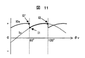
図4に示す電流サンプルを実施すると、I0sとして検出される電流相が、θv の60度毎に変化する。ここで図11のように、観測できる電流相が変化した直後の電流値をI1 とし、変化する直前の値をI2 と定義する。今、θv が60〜120度期間であると仮定する。この期間では、U相電流が観測できるため、I1 、ならびにI2 は、数4を用いて、 When the current sample shown in FIG. 4 is performed, the current phase detected as I 0s changes every 60 degrees of θ v . Here, as shown in FIG. 11, the current value immediately after the change of the observable current phase is defined as I 1, and the value immediately before the change is defined as I 2 . Now, θ v is assumed to be 60 to 120 degrees period. Since U-phase current can be observed during this period, I 1 and I 2 are
と表すことができる。数8より、
It can be expressed as. From
となる。数5より、Ia ,Ir は、 It becomes. From Equation 5, I a and I r are
となる。よって、検出できる電流相が切り替わる前後の電流サンプル値を用いれば、電動機の有効電流と無効電流を観測できることになる。また、定常状態においては、図11に示すように、I2′=I2 であるので、I1 とI2′を用いて演算することもできる。本方式によれば、演算遅れが伴わずに有効電流と無効電流を演算することができる。 It becomes. Therefore, if the current sample values before and after the detectable current phase is switched are used, the effective current and reactive current of the motor can be observed. Further, in the steady state, as shown in FIG. 11, since I 2 ′ = I 2 , the calculation can be performed using I 1 and I 2 ′. According to this method, the effective current and the reactive current can be calculated without any calculation delay.
このように、有効電流と無効電流が観測できると、電動機電流の位相情報が得られることになり、より高度な電動機制御が実現できるようになる。図10では、無効電流Irに対して、電流指令Ir *を与え、無効電流が所定値になるように制御を行っている。無効電流を制御することで、電動機の効率最適化運転や、界磁弱め制御等の実現が可能になり、より高性能な交流電動機の制御装置が提供できる。 Thus, if the effective current and the reactive current can be observed, the phase information of the motor current can be obtained, and more advanced motor control can be realized. In Figure 10, relative to the reactive current I r, giving a current command I r *, reactive current control is performed to a predetermined value. By controlling the reactive current, it becomes possible to realize an efficiency optimization operation of the electric motor, a field weakening control, and the like, and a higher-performance AC motor control device can be provided.
(実施例4)
次に、図12、ならびに図13を用いて、本発明による実施例4について説明する。
Example 4
Next,
電動機に流れる有効電流、ならびに無効電流の検出方法に関する実施例3では、演算できるタイミングは、60°に一回しかなかった。従って、ノイズなどの影響を受けることがある。 In Example 3 relating to the detection method of the effective current flowing through the electric motor and the reactive current, the timing that can be calculated was only once at 60 °. Therefore, it may be affected by noise and the like.
実施例4は、ノイズの影響を受け難くするために、電流サンプル値I0sを積分することにより有効電流,無効電流を演算する手法を提供するものである。 The fourth embodiment provides a method for calculating the effective current and the reactive current by integrating the current sample value I 0s in order to make it less susceptible to noise.
図12は、制御器2Dのブロック構成を示すものである。図12においては、I0sから電動機に流れる有効電流成分Ia と、無効電流成分Ir を演算するIa・Ir演算器18Dと、Ia・Ir演算器18Dで用いる周期関数Fc 、ならびにFs を発生する関数発生器21と、無効電流Ir に対して、指令電流Ir *を与えるIr *発生器20と、が、これまでの実施例における制御器2,2A,2Cと異なる部分である。
FIG. 12 shows a block configuration of the
次に、本実施例の動作原理について説明する。図12に示す制御器2Dは、動作としては、基本的に図10のものと同等であるが、Ia,Irの求め方が大きく異なっている。
Next, the operation principle of this embodiment will be described. The operation of the
関数発生器21は、図13に示す波形(Fc(θv),Fs(θv))を発生する。関数Fs は、sinθvの60度〜120度期間の波形を繰り返し出力する関数であり、関数Fc は、cosθvの60〜120度期間の波形を繰り返すものである。
The
Ia・Ir演算器18Dでは、下記に示す積分演算を行う。 The I a / I r calculator 18D performs the following integral calculation.
上式において、θv0は任意の電圧指令位相である。 In the above equation, θ v0 is an arbitrary voltage command phase.
今、θv が60〜120度である場合について、動作原理を説明する。この期間では、Fs=sinθv,Fc=cosθvであり、また、I0sも、数4で表すことが可能である。数13を展開すると、下記のようになる。
Now, the case theta v is 60 to 120 degrees, illustrating the operation principle. In this period, F s = sin θ v and F c = cos θ v , and I 0s can also be expressed by Equation 4. When
よって、数15より、
Therefore, from
となり、Iamから、有効電流Ia が演算できる。 Thus, the effective current I a can be calculated from I am .
同様に、数14を展開すると、
Similarly, when the
となる。 It becomes.
よって、数15より、
Therefore, from
となり、Irmから、無効電流Ir が演算できる。 Thus, the reactive current I r can be calculated from I rm .
実施例4では、積分演算により、60度以内で、有効電流Ia と無効電流Ir を演算することができる。積分演算のため、ノイズなどの外的要因に対する影響を受け難くなり、より、精度が高く、安定度の増した交流電動機の制御装置が実現できる。
(実施例5)
次に、図14、ならびに図15を用いて、実施例5について説明する。
In the fourth embodiment, the effective current I a and the reactive current I r can be calculated within 60 degrees by integral calculation. Because of the integral calculation, it is difficult to be influenced by external factors such as noise, and it is possible to realize a control device for an AC motor with higher accuracy and increased stability.
(Example 5)
Next, Example 5 will be described with reference to FIGS. 14 and 15.
実際の電動機制御では、電動機電流を電動機の磁束軸成分(d軸成分)と、それに直交する成分(q軸成分)に分離して、電動機電流を制御する「ベクトル制御」が用いられることが多い。本実施例は、このベクトル制御を実現するものである。 In actual motor control, “vector control” is often used to control the motor current by separating the motor current into a magnetic flux axis component (d-axis component) and a component (q-axis component) orthogonal thereto. . In the present embodiment, this vector control is realized.
図14は、制御器2Eのブロック構成を示すものである。図14においては、有効電流成分Ia 、ならびに無効電流成分Ir から、電動機の磁束軸を基準にしたIdc,Iqc軸の電流を演算するar−dq変換器22と、d軸上の電流指令Id *を発生するId *発生器23と、回転速度指令ωr *と速度推定値ωr の差を演算しq軸上の電流指令Iq *を出力する速度制御器24と、電動機のd軸位置(位相)と制御上の位相(θdc)との軸誤差Δθを演算する軸誤差推定器25と、軸誤差Δθが零になるように回転速度を修正するPLL制御器26とが、これまでの実施例における制御器2,2A,2C,2Dと異なる部分である。また、Idc、ならびにIqcが、それぞれId *,Iq *に一致するように、電流制御器12を備えている。
FIG. 14 shows a block configuration of the controller 2E. In FIG. 14, an ar-dq
次に、本実施例の動作について説明する。 Next, the operation of this embodiment will be described.
Ia・Ir演算器18Dにおいて得られたIa 、ならびにIr に基づいて、ar−dq変換器22において、Idc,Iqcが演算される。ここでは、数19に従って、Idc,Iqcを求める。
I a · I r I a obtained in the
尚、数19におけるψは、電圧位相とq軸の相差角であり、
In
と求めることができる。これらの電動機の電圧と、電流の位相関係を、図15に示す。 It can be asked. The phase relationship between the voltage and current of these motors is shown in FIG.
IdcとIqcは、それぞれ電動機の励磁電流,トルク電流に相当する成分であり、各々の指令値Id *,Iq *に一致するように、電流制御器12により制御される。
I dc and I qc are components corresponding to the excitation current and torque current of the motor, respectively, and are controlled by the
また、軸誤差演算器25では、制御上で仮定しているd軸位相(θdc)と、実際の電動機内のd軸位相との誤差角Δθを推定演算する。Δθは、電圧指令、ならびに電流検出値を用いることで、演算することが可能である。PLL制御器26では、軸誤差Δθが零になるように、電動機速度ωr を出力する。定常的には、Δθは零となり、磁極軸を直接検出することなく、電動機のdq軸と制御上の軸とを一致させることができる。また、ωr は、電動機の回転速度推定値でもあり、回転速度指令ωr *との偏差が零になるように、速度制御器24において、トルク電流指令Iq *が演算される。Iq *は、Iqcと比較され、両者が一致するように電流制御12を介して制御される。また、d軸電流に関しても、Idcが所定値になるように電流制御が行われる。非突極型の磁石モータでは、通常Id *=0である。
The
以上のように、本実施例によれば、電動機のトルク電流と励磁電流の個別制御が可能となり、ベクトル制御が実現可能となる。 As described above, according to the present embodiment, individual control of the torque current and excitation current of the electric motor is possible, and vector control can be realized.
(実施例6)
次に、図16を用いて、本発明の実施例6について説明する。
(Example 6)
Next, Embodiment 6 of the present invention will be described with reference to FIG.
本実施例では、中高速以上において高速応答が可能な制御装置を提供する。 In this embodiment, a control device capable of high-speed response at medium and high speeds is provided.
図16は、制御器2Fのブロック構成を示すものである。図16においては、I0 を三角波キャリアの半周期内で2ケ所サンプリングするための電流サンプラー9を2個追加しており、相電流再現器27において、電動機の三相電流を再現する。この相電流再現方法に関しては、特開平2−197295号に記載されている従来技術を用いてもよい。三相電流をdq変換器28において座標変換し、スイッチ29により、Idc,Iqcの演算値を切り替えている。
FIG. 16 shows a block configuration of the
インバータで電動機を駆動する場合、速度が低いほど、ならびに、キャリア周波数が高いほど、インバータのゲートパルス信号は狭くなり、相電流再現器27の動作が困難になる。しかしながら、そのような条件の場合には、2つのスイッチ29をそれぞれ上側に切り替え、Ia・Irから演算する電流検出へ切り替える。逆に、パルス幅が十分に大きな場合には、電流再現器27による電動機電流の検出を行い、高応答な電流制御を実現する。
When driving an electric motor with an inverter, the lower the speed and the higher the carrier frequency, the narrower the gate pulse signal of the inverter becomes, and the operation of the phase
以上のように、本実施例によれば、条件によって、電流検出方式を切り替えることで、より高性能な電動機の制御装置が実現できるようになる。 As described above, according to the present embodiment, a higher-performance motor control device can be realized by switching the current detection method depending on conditions.
(実施例7)
図17は、本発明による交流電動機制御装置の模式図である。図に示す部品番号1〜3,5,6,41,42,43は、図1における同じ番号のものと同一のものである。
(Example 7)
FIG. 17 is a schematic diagram of an AC motor control device according to the present invention. The part numbers 1 to 3, 5, 6, 41, 42, and 43 shown in the figure are the same as those having the same numbers in FIG.
本実施例では、制御器2と、インバータ3と、電流検出器6と、ダイオード・ブリッジ42を一体化し、モジュール化した点に特徴がある。モジュールには、回転数指令発生器1からの回転数指令信号と、電源41の入力端子,平滑コンデンサ43の接続端子,交流電動機5の接続端子が設けられており、その他の部品はすべてモジュール内に収められている。なお本実施例では、回転数指令発生器1は、マイコンを用いている。モジュール内では、マイコンを用いた制御器2と、スイッチングデバイスで構成されたインバータ3,シャント抵抗からなる電流検出器6,ダイオード・ブリッジ42が収められている。
This embodiment is characterized in that the
これまで説明した実施例によれば、位置センサレス・電流センサレスによる交流電動機の高性能な制御装置が、安価なマイコンで実現できるため、このような制御装置のモジュール化が実現できる。 According to the embodiments described so far, a high-performance control device for an AC motor without a position sensor and a current sensor can be realized by an inexpensive microcomputer, and thus such a control device can be modularized.
この結果、パワーモジュールを一つの部品のように扱うことができ、組み立てが容易になると同時に、装置全体の小形化が可能になる。 As a result, the power module can be handled like a single component, and assembling becomes easy, and at the same time, the entire apparatus can be miniaturized.
1…回転数指令発生器、2…制御器、3…インバータ、4…直流電源、5…交流電動機、6…電流検出器、7…変換ゲイン、8…積分器、9…電流サンプラー、10…I0s * 発生器、11…加算器、12…電流制御器、13…dq逆変換器、14…PWM発生器、31…インバータ主回路部、32…ゲート・ドライバ、41…交流電源、42…ダイオード・ブリッジ、43…平滑コンデンサ。
DESCRIPTION OF
Claims (2)
直流電源がインバータへ供給する電流を検出する電流検出手段によって検出されたインバータ電流をPWMの搬送波信号の半周期に一度サンプルするサンプル手段を設け、
前記搬送波信号の正のピーク値と負のピーク値の中間時刻をトリガとし、
前記サンプル手段は、前記トリガを用いて前記インバータ電流値をサンプルすることを特徴とする交流電動機の制御方法。 In the control method of the AC motor that controls the inverter that drives the AC motor using a sinusoidal continuous current,
Sample means for sampling the inverter current detected by the current detection means for detecting the current supplied to the inverter by the DC power supply once in a half cycle of the PWM carrier signal ,
Triggered by an intermediate time between the positive peak value and the negative peak value of the carrier signal,
The AC motor control method according to claim 1, wherein the sampling means samples the inverter current value using the trigger.
直流電源がインバータへ供給する電流を検出する電流検出手段によって検出されたインバータ電流をPWMの搬送波信号の半周期に一度サンプルするサンプル手段を設け、
前記搬送波信号の正のピーク値と負のピーク値の中間時刻をトリガとし、
前記サンプル手段は、前記トリガを用いて前記インバータ電流値をサンプルすることを特徴とする交流電動機の制御装置。 In an AC motor control device that controls an inverter that drives an AC motor using a sinusoidal continuous current,
Sample means for sampling the inverter current detected by the current detection means for detecting the current supplied to the inverter by the DC power supply once in a half cycle of the PWM carrier signal ,
Triggered by an intermediate time between the positive peak value and the negative peak value of the carrier signal,
The said sample means samples the said inverter electric current value using the said trigger, The control apparatus of the AC motor characterized by the above-mentioned.
Priority Applications (1)
| Application Number | Priority Date | Filing Date | Title |
|---|---|---|---|
| JP2007147609A JP4663684B2 (en) | 2007-06-04 | 2007-06-04 | AC motor control device and control method |
Applications Claiming Priority (1)
| Application Number | Priority Date | Filing Date | Title |
|---|---|---|---|
| JP2007147609A JP4663684B2 (en) | 2007-06-04 | 2007-06-04 | AC motor control device and control method |
Related Parent Applications (1)
| Application Number | Title | Priority Date | Filing Date |
|---|---|---|---|
| JP2003074750A Division JP2004282969A (en) | 2003-03-19 | 2003-03-19 | Control apparatus and method for ac motor |
Publications (3)
| Publication Number | Publication Date |
|---|---|
| JP2007221999A JP2007221999A (en) | 2007-08-30 |
| JP2007221999A5 JP2007221999A5 (en) | 2009-02-12 |
| JP4663684B2 true JP4663684B2 (en) | 2011-04-06 |
Family
ID=38498614
Family Applications (1)
| Application Number | Title | Priority Date | Filing Date |
|---|---|---|---|
| JP2007147609A Expired - Lifetime JP4663684B2 (en) | 2007-06-04 | 2007-06-04 | AC motor control device and control method |
Country Status (1)
| Country | Link |
|---|---|
| JP (1) | JP4663684B2 (en) |
Families Citing this family (7)
| Publication number | Priority date | Publication date | Assignee | Title |
|---|---|---|---|---|
| JP5178335B2 (en) * | 2008-06-17 | 2013-04-10 | 株式会社日立製作所 | AC motor control device |
| JP4926145B2 (en) * | 2008-09-16 | 2012-05-09 | 三菱電機株式会社 | AC / DC converter, compressor drive, air conditioner, and abnormality detector |
| JP5278091B2 (en) * | 2009-03-26 | 2013-09-04 | 株式会社明電舎 | Induction motor rotation speed estimation apparatus and estimation method |
| JP5292363B2 (en) | 2010-06-30 | 2013-09-18 | 株式会社日立製作所 | AC motor control device and control method |
| JP5492826B2 (en) * | 2011-06-16 | 2014-05-14 | 日立アプライアンス株式会社 | AC motor control device and refrigeration air conditioner using the same |
| JP5351246B2 (en) * | 2011-12-12 | 2013-11-27 | 山洋電気株式会社 | Motor control device |
| JP7464513B2 (en) | 2020-12-11 | 2024-04-09 | 日立グローバルライフソリューションズ株式会社 | AC motor control device and vacuum cleaner using the same |
-
2007
- 2007-06-04 JP JP2007147609A patent/JP4663684B2/en not_active Expired - Lifetime
Also Published As
| Publication number | Publication date |
|---|---|
| JP2007221999A (en) | 2007-08-30 |
Similar Documents
| Publication | Publication Date | Title |
|---|---|---|
| JP2004282969A (en) | Control apparatus and method for ac motor | |
| JP3681318B2 (en) | Synchronous motor control device and vehicle using the same | |
| JP3972124B2 (en) | Synchronous motor speed control device | |
| JP3979561B2 (en) | AC motor drive system | |
| US7482777B2 (en) | Motor control device | |
| EP1107448B1 (en) | Motor control device | |
| JP3668870B2 (en) | Synchronous motor drive system | |
| JP4022630B2 (en) | Power conversion control device, power conversion control method, and program for power conversion control | |
| JP4663684B2 (en) | AC motor control device and control method | |
| US8461796B2 (en) | Motor drive circuit for driving a synchronous motor | |
| JP3783159B2 (en) | Synchronous motor drive control device | |
| US20070296371A1 (en) | Position sensorless control apparatus for synchronous motor | |
| JP3843391B2 (en) | Synchronous motor drive | |
| JP5358081B2 (en) | Motor control device and motor device | |
| KR20120002477A (en) | Control device and control method of ac motor | |
| WO2020013084A1 (en) | Permanent magnet synchronous machine control device, electric vehicle, and method of determining magnetic pole polarity of permanent magnet synchronous machine | |
| JP4632157B2 (en) | Permanent magnet motor drive system | |
| JP5278723B2 (en) | Motor control device and motor control method | |
| CN109525161B (en) | Integrated circuit for motor control | |
| JP2005237172A (en) | Control device for synchronous machine | |
| JP2004289898A (en) | Drive device for stepping motor | |
| JP4535082B2 (en) | Sensorless control device and control method for synchronous generator | |
| JP7154987B2 (en) | Control device for permanent magnet synchronous motor, microcomputer, motor system, and method of operating permanent magnet synchronous motor | |
| Kennel et al. | " Sensorless" control of 4-quadrant-rectifiers for voltage source inverters (VSI) | |
| JP3797484B2 (en) | Stepping motor drive device |
Legal Events
| Date | Code | Title | Description |
|---|---|---|---|
| A621 | Written request for application examination |
Free format text: JAPANESE INTERMEDIATE CODE: A621 Effective date: 20070604 |
|
| A521 | Request for written amendment filed |
Free format text: JAPANESE INTERMEDIATE CODE: A523 Effective date: 20081222 |
|
| A131 | Notification of reasons for refusal |
Free format text: JAPANESE INTERMEDIATE CODE: A131 Effective date: 20100727 |
|
| A521 | Request for written amendment filed |
Free format text: JAPANESE INTERMEDIATE CODE: A523 Effective date: 20100910 |
|
| TRDD | Decision of grant or rejection written | ||
| A01 | Written decision to grant a patent or to grant a registration (utility model) |
Free format text: JAPANESE INTERMEDIATE CODE: A01 Effective date: 20101221 |
|
| A01 | Written decision to grant a patent or to grant a registration (utility model) |
Free format text: JAPANESE INTERMEDIATE CODE: A01 |
|
| A61 | First payment of annual fees (during grant procedure) |
Free format text: JAPANESE INTERMEDIATE CODE: A61 Effective date: 20110105 |
|
| R150 | Certificate of patent or registration of utility model |
Ref document number: 4663684 Country of ref document: JP Free format text: JAPANESE INTERMEDIATE CODE: R150 Free format text: JAPANESE INTERMEDIATE CODE: R150 |
|
| FPAY | Renewal fee payment (event date is renewal date of database) |
Free format text: PAYMENT UNTIL: 20140114 Year of fee payment: 3 |
|
| S111 | Request for change of ownership or part of ownership |
Free format text: JAPANESE INTERMEDIATE CODE: R313117 |
|
| R350 | Written notification of registration of transfer |
Free format text: JAPANESE INTERMEDIATE CODE: R350 |
|
| S111 | Request for change of ownership or part of ownership |
Free format text: JAPANESE INTERMEDIATE CODE: R313117 |
|
| S531 | Written request for registration of change of domicile |
Free format text: JAPANESE INTERMEDIATE CODE: R313531 |
|
| R350 | Written notification of registration of transfer |
Free format text: JAPANESE INTERMEDIATE CODE: R350 |
|
| S111 | Request for change of ownership or part of ownership |
Free format text: JAPANESE INTERMEDIATE CODE: R313117 |
|
| R350 | Written notification of registration of transfer |
Free format text: JAPANESE INTERMEDIATE CODE: R350 |
|
| EXPY | Cancellation because of completion of term |