JP4662975B2 - Single panel golf club grip with EVA inner layer - Google Patents
Single panel golf club grip with EVA inner layer Download PDFInfo
- Publication number
- JP4662975B2 JP4662975B2 JP2007502127A JP2007502127A JP4662975B2 JP 4662975 B2 JP4662975 B2 JP 4662975B2 JP 2007502127 A JP2007502127 A JP 2007502127A JP 2007502127 A JP2007502127 A JP 2007502127A JP 4662975 B2 JP4662975 B2 JP 4662975B2
- Authority
- JP
- Japan
- Prior art keywords
- panel
- grip
- polyurethane
- seam
- golf club
- Prior art date
- Legal status (The legal status is an assumption and is not a legal conclusion. Google has not performed a legal analysis and makes no representation as to the accuracy of the status listed.)
- Expired - Fee Related
Links
Images


Classifications
-
- A—HUMAN NECESSITIES
- A63—SPORTS; GAMES; AMUSEMENTS
- A63B—APPARATUS FOR PHYSICAL TRAINING, GYMNASTICS, SWIMMING, CLIMBING, OR FENCING; BALL GAMES; TRAINING EQUIPMENT
- A63B53/00—Golf clubs
- A63B53/14—Handles
-
- A—HUMAN NECESSITIES
- A63—SPORTS; GAMES; AMUSEMENTS
- A63B—APPARATUS FOR PHYSICAL TRAINING, GYMNASTICS, SWIMMING, CLIMBING, OR FENCING; BALL GAMES; TRAINING EQUIPMENT
- A63B49/00—Stringed rackets, e.g. for tennis
- A63B49/02—Frames
- A63B49/08—Frames with special construction of the handle
-
- A—HUMAN NECESSITIES
- A63—SPORTS; GAMES; AMUSEMENTS
- A63B—APPARATUS FOR PHYSICAL TRAINING, GYMNASTICS, SWIMMING, CLIMBING, OR FENCING; BALL GAMES; TRAINING EQUIPMENT
- A63B60/00—Details or accessories of golf clubs, bats, rackets or the like
- A63B60/06—Handles
- A63B60/08—Handles characterised by the material
-
- A—HUMAN NECESSITIES
- A63—SPORTS; GAMES; AMUSEMENTS
- A63B—APPARATUS FOR PHYSICAL TRAINING, GYMNASTICS, SWIMMING, CLIMBING, OR FENCING; BALL GAMES; TRAINING EQUIPMENT
- A63B60/00—Details or accessories of golf clubs, bats, rackets or the like
- A63B60/06—Handles
- A63B60/14—Coverings specially adapted for handles, e.g. sleeves or ribbons
-
- A—HUMAN NECESSITIES
- A63—SPORTS; GAMES; AMUSEMENTS
- A63B—APPARATUS FOR PHYSICAL TRAINING, GYMNASTICS, SWIMMING, CLIMBING, OR FENCING; BALL GAMES; TRAINING EQUIPMENT
- A63B60/00—Details or accessories of golf clubs, bats, rackets or the like
- A63B60/54—Details or accessories of golf clubs, bats, rackets or the like with means for damping vibrations
-
- B—PERFORMING OPERATIONS; TRANSPORTING
- B32—LAYERED PRODUCTS
- B32B—LAYERED PRODUCTS, i.e. PRODUCTS BUILT-UP OF STRATA OF FLAT OR NON-FLAT, e.g. CELLULAR OR HONEYCOMB, FORM
- B32B27/00—Layered products comprising a layer of synthetic resin
- B32B27/06—Layered products comprising a layer of synthetic resin as the main or only constituent of a layer, which is next to another layer of the same or of a different material
- B32B27/08—Layered products comprising a layer of synthetic resin as the main or only constituent of a layer, which is next to another layer of the same or of a different material of synthetic resin
-
- B—PERFORMING OPERATIONS; TRANSPORTING
- B32—LAYERED PRODUCTS
- B32B—LAYERED PRODUCTS, i.e. PRODUCTS BUILT-UP OF STRATA OF FLAT OR NON-FLAT, e.g. CELLULAR OR HONEYCOMB, FORM
- B32B27/00—Layered products comprising a layer of synthetic resin
- B32B27/30—Layered products comprising a layer of synthetic resin comprising vinyl (co)polymers; comprising acrylic (co)polymers
- B32B27/306—Layered products comprising a layer of synthetic resin comprising vinyl (co)polymers; comprising acrylic (co)polymers comprising vinyl acetate or vinyl alcohol (co)polymers
-
- B—PERFORMING OPERATIONS; TRANSPORTING
- B32—LAYERED PRODUCTS
- B32B—LAYERED PRODUCTS, i.e. PRODUCTS BUILT-UP OF STRATA OF FLAT OR NON-FLAT, e.g. CELLULAR OR HONEYCOMB, FORM
- B32B27/00—Layered products comprising a layer of synthetic resin
- B32B27/32—Layered products comprising a layer of synthetic resin comprising polyolefins
-
- B—PERFORMING OPERATIONS; TRANSPORTING
- B32—LAYERED PRODUCTS
- B32B—LAYERED PRODUCTS, i.e. PRODUCTS BUILT-UP OF STRATA OF FLAT OR NON-FLAT, e.g. CELLULAR OR HONEYCOMB, FORM
- B32B27/00—Layered products comprising a layer of synthetic resin
- B32B27/40—Layered products comprising a layer of synthetic resin comprising polyurethanes
-
- A—HUMAN NECESSITIES
- A63—SPORTS; GAMES; AMUSEMENTS
- A63B—APPARATUS FOR PHYSICAL TRAINING, GYMNASTICS, SWIMMING, CLIMBING, OR FENCING; BALL GAMES; TRAINING EQUIPMENT
- A63B60/00—Details or accessories of golf clubs, bats, rackets or the like
- A63B60/06—Handles
- A63B60/16—Caps; Ferrules
-
- A—HUMAN NECESSITIES
- A63—SPORTS; GAMES; AMUSEMENTS
- A63B—APPARATUS FOR PHYSICAL TRAINING, GYMNASTICS, SWIMMING, CLIMBING, OR FENCING; BALL GAMES; TRAINING EQUIPMENT
- A63B60/00—Details or accessories of golf clubs, bats, rackets or the like
- A63B60/06—Handles
- A63B60/18—Handles with means for cooling, ventilating or sweat-reduction, e.g. holes or powder dispensers
-
- B—PERFORMING OPERATIONS; TRANSPORTING
- B32—LAYERED PRODUCTS
- B32B—LAYERED PRODUCTS, i.e. PRODUCTS BUILT-UP OF STRATA OF FLAT OR NON-FLAT, e.g. CELLULAR OR HONEYCOMB, FORM
- B32B2307/00—Properties of the layers or laminate
- B32B2307/50—Properties of the layers or laminate having particular mechanical properties
- B32B2307/56—Damping, energy absorption
-
- B—PERFORMING OPERATIONS; TRANSPORTING
- B32—LAYERED PRODUCTS
- B32B—LAYERED PRODUCTS, i.e. PRODUCTS BUILT-UP OF STRATA OF FLAT OR NON-FLAT, e.g. CELLULAR OR HONEYCOMB, FORM
- B32B2307/00—Properties of the layers or laminate
- B32B2307/70—Other properties
- B32B2307/726—Permeability to liquids, absorption
- B32B2307/7265—Non-permeable
-
- B—PERFORMING OPERATIONS; TRANSPORTING
- B32—LAYERED PRODUCTS
- B32B—LAYERED PRODUCTS, i.e. PRODUCTS BUILT-UP OF STRATA OF FLAT OR NON-FLAT, e.g. CELLULAR OR HONEYCOMB, FORM
- B32B2323/00—Polyalkenes
- B32B2323/04—Polyethylene
-
- B—PERFORMING OPERATIONS; TRANSPORTING
- B32—LAYERED PRODUCTS
- B32B—LAYERED PRODUCTS, i.e. PRODUCTS BUILT-UP OF STRATA OF FLAT OR NON-FLAT, e.g. CELLULAR OR HONEYCOMB, FORM
- B32B2331/00—Polyvinylesters
- B32B2331/04—Polymers of vinyl acetate, e.g. PVA
-
- B—PERFORMING OPERATIONS; TRANSPORTING
- B32—LAYERED PRODUCTS
- B32B—LAYERED PRODUCTS, i.e. PRODUCTS BUILT-UP OF STRATA OF FLAT OR NON-FLAT, e.g. CELLULAR OR HONEYCOMB, FORM
- B32B2375/00—Polyureas; Polyurethanes
Landscapes
- Health & Medical Sciences (AREA)
- General Health & Medical Sciences (AREA)
- Physical Education & Sports Medicine (AREA)
- Golf Clubs (AREA)
Description
本発明は、ゴルフクラブ用の改良されたグリップに関する。 The present invention relates to an improved grip for a golf club.
出願人は以前に、ユーザの筋肉と腕の関節に対するゴルフクラブの衝撃を低減し、またプレーヤの手とグリップとの間の粘着性の感覚も備える、弾力性のあるグリップを開発するのに成功した。例えば1998年4月25日に出願人に登録された米国特許第5,797,813号明細書を参照されたい。そのような初期のグリップは、ゴルフクラブ用握り部上で滑らされ、また接着される下地スリーブ(underlisting sleeve)の周囲に、らせん状に巻き付けられるポリウレタン製フェルトの細長片を利用する。細長片の両側面は、加熱押圧された凹所の強化端部を重畳することにより形成される。そのようなグリップは衝撃を低減するのに十分であるが、具体的に細長片が特定の圧力パラメータの範囲で下地スリーブの周囲に手動で巻き付けられる必要があるので、それらの加工は労働集約的である。さらに、そのような細長片が下地スリーブの周囲にらせん状に巻き付けられるように、細長片の隣接する両側端部を正確に整列させることは難しい。そのように巻き付けられたグリップの細長片は、巻き付け処理中に捩られた状態になる場合がある。パター用グリップに巻き付けるとき、これは特に難しい問題である。これらの巻き付けられたグリップは、装飾図案の表示にも適さない。 Applicants have previously developed a resilient grip that reduces the impact of the golf club on the user's muscles and arm joints and also provides a sense of stickiness between the player's hand and grip. did. See, for example, US Pat. No. 5,797,813, filed April 25, 1998 by the applicant. Such early grips utilize a strip of polyurethane felt that is spirally wrapped around an underlisting sleeve that is slid and glued onto a golf club grip . Both side surfaces of the elongated piece are formed by superimposing the reinforced end portions of the heat-pressed recess. Such grips are sufficient to reduce impact, but their processing is labor intensive, specifically because the strips need to be manually wrapped around the underlying sleeve in a range of specific pressure parameters. It is. Furthermore, it is difficult to accurately align adjacent side edges of the strip so that the strip is spirally wrapped around the base sleeve . The strip of grip so wound may become twisted during the winding process. This is a particularly difficult problem when wrapped around a putter grip. These wrapped grips are also not suitable for displaying decorative designs.
所望する衝撃吸収特性を備える従来技術のポリウレタン/フェルト製グリップが開発されてきたが、フェルト材料は水分を吸収しやすい。従って、グリップは、ユーザの手から汗を吸収する傾向があり、またプレー中に飽和状態に達し、それによってユーザの手の中でゴルフクラブあるいはテニスラケットの滑りが生ずる。同様の問題は、雨中でゴルフをするときなど湿潤状態下で生ずる。この問題を解決するために、出願人は、フェルト基材の代用品としてEVA(エチレン−ビニール・アセテート共ポリマ)を使用した。例えば、2003年9月30日に出願人に登録された米国特許第6,627,027号明細書を参照されたい。 Prior art polyurethane / felt grips with the desired shock absorbing properties have been developed, but the felt material tends to absorb moisture. Thus, the grip tends to absorb sweat from the user's hand and reaches saturation during play, thereby causing the golf club or tennis racket to slip in the user's hand. Similar problems occur under wet conditions, such as when playing golf in the rain. To solve this problem, the applicant has used EVA (ethylene-vinyl acetate copolymer) as a substitute for felt substrates. See, for example, US Pat. No. 6,627,027, registered with the applicant on September 30, 2003.
一つの実施態様において、ゴルフクラブ用グリップは、粘着性を備え、グリップの全重量を低減し、前述の利点を低減できる耐吸水性を備えるのみならず、そのようなグリップにより付与される同一の耐衝撃性を備える一方、従来のらせん状に巻き付けられたグリップの前述の欠点を克服する。欠点は、下地スリーブの外部形状に対応している形状を有する、単一のポリウレタン-EVA製パネルから一体構造のグリップを形成することにより解消される。そのような単一パネルの両側端部は、互いに接触し、また好ましくは共に接着され、その結果パネルを貫いて延びている長手方向継ぎ目を形成する。加熱形成された凹所の封鎖用チャネルが、そのような継ぎ目を強化するために継ぎ目の外端部にあるポリウレタン層の外部に形成される。ホットなポリウレタンが、継ぎ目に沿って、あるいはチャネルの内部に堆積され、またそのポリウレタンは固化後に、グリップの表面に滑らかに一体化するためにバフ研磨される。別の改良において、グリップ表面の主体の摩擦増強パターンに適合するよう、堆積されたポリウレタンの上方に摩擦増強パターンをエンボス加工するために、モールドが利用される。 In one embodiment, the golf club grip is not only provided with tackiness, water absorption resistance that can reduce the overall weight of the grip and reduce the aforementioned benefits, but also the same grip provided by such grip. While providing impact resistance, it overcomes the aforementioned drawbacks of conventional helically wound grips. The disadvantages are eliminated by forming a monolithic grip from a single polyurethane-EVA panel having a shape that corresponds to the external shape of the underlying sleeve . The side edges of such a single panel are in contact with each other and are preferably bonded together, thereby forming a longitudinal seam extending through the panel. A heat-formed recess sealing channel is formed outside the polyurethane layer at the outer end of the seam to reinforce such a seam. Hot polyurethane is deposited along the seam or inside the channel, and the polyurethane is buffed after solidification to smoothly integrate into the grip surface. In another improvement, a mold is utilized to emboss the friction enhancing pattern over the deposited polyurethane to match the main friction enhancing pattern on the grip surface.
別の実施態様は、下地スリーブと単一パネルとを含んでいる、ゴルフクラブの握り部用のグリップである。下地スリーブは、ゴルフクラブの握り部上へ入れ子式に滑らされる。単一のパネルは、ポリマの内層に接合されるポリマの外層を含む。パネルは、互いに接触するパネルの両側端部を備え、下地スリーブの周囲に巻き付けられ、また接着され、その結果内層の内表面から外層の外表面へ延びている長手方向継ぎ目を形成する。両側端部は共に接着されるのが好ましい。別の実施態様において、ポリマ物質が継ぎ目に沿って堆積される。別の実施態様において、加熱押圧されたチャネルが継ぎ目の外部に形成される。別の実施態様において、チャネルは堆積されたポリマで充填される。さらに別の実施態様において、ポリマデポジットは平滑バフ研磨される。さらに別の実施態様において、摩擦増強パターンの一部が、外層の外部に形成される摩擦増強パターンに融け込むように継ぎ目の外部に形成される。 Another embodiment is a grip for a golf club grip that includes a base sleeve and a single panel. The base sleeve is slid in a telescoping manner on the grip of the golf club. A single panel includes an outer layer of polymer joined to an inner layer of polymer. The panels comprise opposite side edges of the panels that contact each other and are wrapped around and glued around the underlying sleeve , thereby forming a longitudinal seam extending from the inner surface of the inner layer to the outer surface of the outer layer. Both end portions are preferably bonded together. In another embodiment, polymer material is deposited along the seam. In another embodiment, a heated pressed channel is formed outside the seam. In another embodiment, the channel is filled with a deposited polymer. In yet another embodiment, the polymer deposit is smooth buffed. In yet another embodiment, a portion of the friction enhancing pattern is formed on the exterior of the seam so as to merge into the friction enhancing pattern formed on the exterior of the outer layer.
別の実施態様は、ゴルフクラブの握り部上に入れ子式に滑らされる下地スリーブを提供する工程と、EVA製内層に接合されるポリウレタン製外層を含み、弾力性のあるスリーブの外部形状に対応している形状を有する単一パネルを提供する工程と、単一パネルを下地スリーブの周囲に巻き付けし、またそれを接着する工程と、内層の内表面から外層の外表面へ延びている長手方向継ぎ目を形成するために、パネルの両側端部を接触させる工程と、を含んでいるゴルフクラブの握り部用のグリップを作製する方法である。 Another embodiment includes providing a base sleeve that is telescopically slid onto the grip of a golf club and a polyurethane outer layer joined to the EVA inner layer to accommodate the outer shape of the resilient sleeve Providing a single panel having the shape of the substrate , wrapping the single panel around the base sleeve and bonding it, and a longitudinal direction extending from the inner surface of the inner layer to the outer surface of the outer layer A method for producing a grip for a grip portion of a golf club, comprising the step of contacting both side edges of the panel to form a seam.
ゴルフクラブ用グリップは、従来のらせん状に巻き付けられたグリップよりも大幅に低い価格で製造される。その理由は特定の圧力パラメータの範囲で下地スリーブの周囲に細長片をらせん状に巻き付ける集約労働が解消されるためである。さらに、単一パネルのグリップは、製造中も下地スリーブに接着された後にも捩れないのが望ましい。本発明者の新しいグリップは、プロゴルファと低いハンディキャップのアマチュアとにアピールするように、なるべく従来の成形されたゴム製グリップに類似の概観を有し、また装飾図案の出願に広範な分野を与えるのが望ましい。さらに、本発明者による新しいグリップのEVA製内層は耐吸水性であり、グリップが湿気に晒されるときグリップにより付与される他の利点を維持し続ける。 Golf club grips are manufactured at a significantly lower price than conventional helically wound grips. The reason is that the intensive labor of spirally winding the strip around the base sleeve within a certain pressure parameter range is eliminated. Furthermore, it is desirable that the single panel grips do not twist during manufacture or after being bonded to the underlying sleeve . The inventor's new grip has an overview similar to traditional molded rubber grips as much as possible to appeal to professional golfers and low handicap amateurs, and has a broad field of applications for decorative designs. It is desirable to give. In addition, the EVA inner layer of the new grip by the inventor is water-absorbing and continues to maintain other benefits provided by the grip when the grip is exposed to moisture.
これらと他の目的及び利点は、添付の図面と以下の詳細な説明とから明らかになるであろう。 These and other objects and advantages will become apparent from the accompanying drawings and the following detailed description.
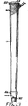
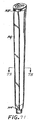
図面を参照すると、図1において、ゴルフクラブGCのシャフト55に取付けられた、本発明の一つの実施態様の単一パネルのグリップGが示される。図2において、パターPのシャフト57に取付けられた、単一パネルのパター用グリップPGが示される。残りの図面を参照すると、グリップGの好適な形態は、共接合された外部あるいはポリマ、好ましくはポリウレタンの層60と内部あるいはポリマ、好ましくはエチレン−ビニール・アセテート共ポリマ(EVA)の層62から形成され、従来構造の弾力性のある下地スリーブUの周囲に巻き付けられ、また接着される単一のパネルSを含む。
Referring to the drawings, FIG. 1 shows a single panel grip G of one embodiment of the present invention attached to a
本開示の、単一パネルの外層60を一般に、ポリウレタン層と呼ぶ。ポリウレタンは好適な材料であるが、他の材料を使用し、またいくつかの利点を達成できる。具体的には、他のポリマ化合物を使用して、外層を創生しまたいくつかの利点を達成できる。同様に、内層62を一般に、EVA層と呼ぶ。EVAは好適であるが、他のポリマの層を、本発明の代わりの実施態様において使用できる。
The single panel
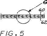
図3−6を参照すると、EVA層62は、凝固して細孔を形成した状態になっているポリウレタン層60の内表面に、接着剤30を用いて固定される外表面を有する(図6に示される)。適切なポリウレタン−EVAシート(示されていない)を形成する一つの好適な方法が、2003年9月30日に出願人に交付された米国特許第6,627,027号明細書に開示される。前述のポリウレタン−EVAシートのポリウレタン層を形成する一つの好適な方法は、例えば、2003年12月23日に出願人により出願された米国特許出願第10/746,764号明細書に開示される。いったんポリウレタン−EVAシートが形成されると、図3に示される形状のパネルSを形成するために、シートは従来方法でプレスカットされるのが好ましい。同一のプレスカットが、パネルSの上端部107と下端部108との中心にそれぞれ切欠きN1と、N2を同様に形成するのが望ましい。切欠きN1とN2は、下地スリーブU上にパネルSを心出しするのを支援するためにマーキングとしての機能を果たす。パネルSの心出しをする他の方法があるが、これらの切欠きN1と、N2が、価格を低減しまた完成されたグリップGの外観に影響しないので好適である。パネルSを心出しする他の方法の一事例は、図16−19と関連して後述される。
Referring to FIGS. 3-6, the
ポリウレタンの層の厚みは、約0.3mm−0.5mmであり、またEVA層の厚みは約0.8mm−1.7mmであるのが好ましい。ポリウレタン層60は、ゴルファの手のクッション付の握りをゴルフクラブに与え、またプレーヤの手とグリップとの間に向上した粘着性を与えることによりゴルファのグリップを強固にする。EVA層62は、ポリウレタン層に強さを与え、また共接合されたポリウレタンとEVAとのパネルを、下地スリーブUに取付けるための耐湿性手段としての機能を果たす。
The thickness of the polyurethane layer is preferably about 0.3 mm to 0.5 mm, and the thickness of the EVA layer is preferably about 0.8 mm to 1.7 mm. The
図7-15を参照すると、ポリウレタン層60の外表面に摩擦増強パターン63を形成するために利用される第一モールドと、単一パネルSの上端部107と下端部108に沿って加熱押圧された水平方向の端部64と65の頂部と底部と、パネル109と、110の両側面に沿って押圧された水平端部66aと66bとがそれぞれ示されている。モールドMは、基板Bと、空洞68を備えて形成される加熱圧板67とを含む。図9に見られるように、空洞68の端部は、押圧された摩擦増強パターン63を形成するように、ポリウレタン層60の外表面に係合する、垂れ下がっている突起69が設けられる。図8において、垂れ下がっている突起69aと69bは、凹所の端部66aと66bとをそれぞれ形成する。図11において、空洞68の右側端部は、ポリウレタン層60に加熱された凹所の上端部64を形成するために、パネルSの上端部107に係合する肩部70を備えて形成されることが分る。空洞の左側は、パネルSの下端部108に沿って加熱押圧された凹所の下端部65を形成するために、類似の肩部71を備えて形成される(図10)。
Referring to FIGS. 7-15, the first mold used to form the
他の実施態様において、他のパターンが、ポリウレタン層60の外表面に形成される。図12は、モールドMが、摩擦増強パターン63を形成するが、パネルSの周縁107と、108と、109と、110とに沿って加熱押圧された端部64と、65と、66aと、66bとを形成しない一つの他の態様を示す。図13に見られるように、別の他の態様は、ロゴ116など目に見える印がパネルSの下端部108付近に設置される一方、外層60の大部分を平滑な状態のままに置いている。図14に、摩擦増強パターンのさらに別の実施態様が示される。第二のパターン118は、図12に示される摩擦増強パターン63に類似のトレッド・パターンで囲まれた、パネルの全長の大部分に延びている目に見える印を組み込んでいる。図14は、装飾図案あるいはロゴをグリップパネルSに付加するための代わりの手段も示す。ロゴ114などスタンプされた目に見える印は、当業者には周知の適切なインクを使用してポリウレタン層60にインクスタンプされる。インクは、防水性と耐熱性であるのが好ましく、またゴルフクラブGC用シャフト55(図1)あるいはパターP用シャフト57(図2)の端部上方の完成されたグリップG(パネルS付の下地スリーブU)に塗布するために使用される潤滑流体あるいは溶剤と接触状態になるとき劣化に耐えるよう考案されるのがより好ましい。これらは代表例であり、また多くの他のパターンとスタンプが、このポリウレタン−EVA製単一パネルのグリップで使用されることが分る。
In other embodiments, other patterns are formed on the outer surface of the
図15は、図12の線15−15に沿った断面図である。それは、連続的なポリウレタン層60上に形成される摩擦増強パターン63を示す。
FIG. 15 is a cross-sectional view taken along line 15-15 in FIG. It shows a
図16−19を参照すると、本発明の一つの実施態様の、単一パネルのグリップGを作製するのに利用される第二のモールドM2が示されている。パネルSは、第一のモールドMの位置から反転されて示されている。モールドM2は、基板71と、空洞73を備えて形成される加熱圧板72を含む。EVA層62が加熱圧板72の空洞73の内部に収納されるとき、基板は同様に、ポリウレタン層60を収納する空洞74を備えて形成される。
加熱圧板72の上端と下端と両側端部は、EVA層62の上端部107と下端部108と両側端部109と110に嵌め込まれる、垂れ下がっている周縁肩部76aと、76bを備えて形成される。加熱圧板72がEVA層に向かって下向きに押圧されるとき、その周縁は肩部76aと、76bにより押圧され、また熱は、ポリウレタン層60の周縁を緻密にするためにEVA層を通って伝達される。第二のモールドM2の加熱圧板72が、図19に示されるEVA層62の長手方向の中心に沿った切り込み線SL−1を形成する、垂れ下がっている棘突起72aも付与されるとき、代わりの心出し切欠きN1と、N2を同時に形成できる。代わりの実施態様において、第二のモールドM2の加熱圧板には、垂れ下がっている肩部76aと、76bがない。むしろ、ポリウレタン層60の周縁107と、108と、109と、110を緻密にすることなしに切り込み線SL−1を形成するための垂れ下がっている棘突起72aのみを有する。
Referring to FIGS. 16-19, there is shown a second mold M2 utilized to make a single panel grip G of one embodiment of the present invention. Panel S is shown inverted from the position of the first mold M. The mold M2 includes a
The upper end, the lower end, and both end portions of the
図20−23を参照すると、図20に示されるようにパネルSの上端部107と下端部108に係合する一対の回転するナイフ120と122と、単一の回転するナイフ124とにより薄く剥がされた状態になっている、パネルSの周辺端部が示されている。ナイフ120と122は、上部と下部の薄く剥がされた端部130と、132を形成する。第一の側面109が薄く剥がされた後に、図21のパネルSの一方の側の薄く剥がされた側端部134と、図22のもう一方の薄く剥がされた側端部136とを形成する、ナイフ124が示されている。加圧プレート83は、スキービング操作の際にパネルSをベース84に固定するために利用される。パネルSの両側面109と、110上のスキービングは互いに平行であるのが好ましく、それは図22に示される。スキービングは約4.0−6.0mmの幅を有するのが好ましい。代わりの実施態様において、上端部107及び/又は下端部108は薄く剥がされない。
Referring to FIGS. 20-23, as shown in FIG. 20, the pair of rotating knives 120 and 122 engaged with the
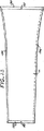
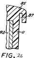
図24−27を参照すると、天然もしくは合成のゴム、あるいはプラスチックなど弾力性のある材料から形成され下地スリーブUが示されている。スリーブUは、その上端部に一体化されたキャップ85を含むが、スリーブの下端部は一体化されたニップル86を備えて形成される。キャップ85の下部側面は、円周方向の下方に延びているスロット87を備えて形成されるのが好ましい。スロット87は、後述のパネルSの薄く剥がされた上端部130を収納するのが好ましい。ニップル86は、後述される方法でパネルSの薄く剥がされた下端部132を受納するように、なるべくならスロット88の外側に形成される周縁リップ89により形成される上方へ延びているスロット88を備えて形成されるのが好ましい。下地スリーブUは、完成されたグリップGを形成するために、下地スリーブUに完成されたグリップ用パネルSを貼り付けるための中点を示している心出し切欠きN3と,N4を備えて形成されるのが好ましい。あるいは、下地スリーブUは、垂直方向に延びている切込み線SL−2を備えて形成されると良い(示されていない)。
Referring to FIGS. 24-27, a base sleeve U is shown formed from a resilient material such as natural or synthetic rubber or plastic. The sleeve U includes a
図28−37を参照すると、下地スリーブUに貼り付けられる状態になっているパネルSが示される。図28において、ノズル、あるいはブラシ等の手段により、接着剤90を塗布される下地スリーブUの外表面が示される。図29において、ノズル、あるいはブラシ等の手段により、接着剤90を塗布されるEVA層62の内表面が示される。
Referring to FIGS. 28-37, a panel S is shown that is ready to be affixed to the underlying sleeve U. FIG. In FIG. 28, the outer surface of the base sleeve U to which the adhesive 90 is applied is shown by means such as a nozzle or a brush. In FIG. 29, the inner surface of the
図30は、下地スリーブUの周囲に巻き付けられまた接着されて示されるパネルSを示す。この操作の際に、パネルSの切欠きN1と、N2は、下地スリーブUの切欠きN3と、N4の下で一直線になって配置される。あるいは、切り込み線SL−1とSL−2は、一直線に配置されると良い。さらに別の実施態様において、切り込み線は、下地スリーブU上にパネルSを心出しするために切欠きと併用して使用される。同様に、パネルSの薄く剥がされた上端部は、下地スリーブのキャップ85のスロット87の内部に手動で挿入されるが、パネルSの薄く剥がされた下端部132は、一時的に柔軟になっている周縁リップ89によりニップル86の内部に外向きに形成されるスロット88の内部に手動で挿入される(図43と44を参照)。
FIG. 30 shows a panel S that is shown wrapped and glued around the base sleeve U. During this operation, the cutouts N1 and N2 of the panel S are arranged in a straight line under the cutouts N3 and N4 of the base sleeve U. Alternatively, the cut lines SL-1 and SL-2 are preferably arranged in a straight line. In yet another embodiment, the score line is used in conjunction with the notch to center the panel S on the underlying sleeve U. Similarly, the thinly peeled upper end of the panel S is manually inserted into the
図35と、36と、37に示されるように、パネルSの薄く剥がされた両側端部134と、136は、パネルを貫いて延びている継ぎ目91を形成するために、適切な接着剤90により共に接着される。両側端部134と、136が薄く剥がされるため、継ぎ目91は、パネルSの奥行きに対し斜めにパネルを貫いて延び、その結果パネルの奥行きに平行に延びている継ぎ目に比較して継ぎ目の長さを増大する。継ぎ目の増大した長さは、より強固な接合を与える。当業者が本発明者の初期の開示を理解しまた検討すると、下地スリーブUにパネルを取付ける別の方法がある。EVA層に接合し、また下地スリーブにポリウレタン/EVAパネルを巻き付けるために使用される適切な接着剤90は、メチル−エチル−ケトン(C6H5CH3)とTS008ポリウレタンの組合せであるのが好ましい。当業者が理解するように、これらの化合物を様々な比率で混合できる、しかしながら、一つの適切な混合の比率は8:1である。当業者が理解しまた本発明者の米国特許第6,627,027号明細書の開示に述べるように、保護紙により被覆される接着被覆剤30を有するEVAを、中国、広東省、東莞市、始掲町、Xin Feng W.路. Xin Xing Ind.区.のHo Ya electric Bond工場から購入できる。液体よりもむしろテープの形式の接着剤90の使用を含んでいるが、それに限定されるものではない、さらに他の可能性が、下地スリーブUにパネルSを固定するために意図される。
As shown in FIGS. 35, 36, and 37, the thinly stripped side edges 134 and 136 of the panel S are suitable adhesive 90 to form a
一つの実施態様において、継ぎ目91はそのままにされ、そして完成されたグリップG−1は図32のグリップと共通点が多い。
In one embodiment, the
図43と44は、図42の線43−43と44−44にそれぞれ沿った拡大断面図を示す。それらは、パネルSが下地スリーブUに接着された後の、パネルSの薄く剥がされた上端部130と薄く剥がされた下端部132の最終配置を明示する。パネルSの薄く剥がされた端部130の上端部は、キャップ85のスロット87の内部に固定して配置される。同様に、薄く剥がされた下端部132は、ニップル86のスロット88の内部に固定して配置される。もちろん、薄く剥がされていない上端部107及び/又は薄く剥がされていない下端部108をそれぞれスロット87あるいは88に挿入することも可能である。完成されたグリップは次に、マンドレル92から取り除かれ、またゴルフクラブGCあるいはパターP用シャフトに従来方法で滑らされまた固定される状態に準備される。
43 and 44 show enlarged cross-sectional views along lines 43-43 and 44-44 of FIG. 42, respectively. They demonstrate the final arrangement of the thinly peeled
図38−42を参照すると、パネルSが下地スリーブUに接着された後の実施態様が示される。図38は、長手方向に延びている加熱された加圧歯部94(図39)が継ぎ目91の外端部にあるポリウレタン層60に対して押圧される場合の、マンドレル92によりベース93上に支持される下地スリーブUを示す。加熱された歯部94は、継ぎ目91をさらに強化するように、継ぎ目91の外端部と一直線にされた小さな凹部95をポリウレタン層60に形成する。完成されたグリップG−2の実施態様は、図42に示される。
38-42, the embodiment after the panel S has been bonded to the base sleeve U is shown. FIG. 38 shows that the heated pressure tooth 94 (FIG. 39) extending in the longitudinal direction is pressed onto the base 93 by the
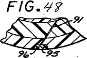
図45−48は、凹部95がノズル、あるいはブラシ等によりホットなポリウレタン96で充填されることを除いて、グリップG−2に類似のゴルフクラブ用グリップG−3を示す(図45)。ポリウレタン96の固化後に、図46に示されるようにグリップの表面に滑らかに一体になるために、適切なブラシ等97により凹部をバフ研磨できる。あるいは、チャネル95は、ホットなポリウレタン96で充填される後はバフ研磨されない。
45-48 shows a golf club grip G-3 similar to the grip G-2 except that the
図49−52を参照すると、グリップG−4の別の実施態様が示されている。グリップG−4は、チャネル95を使用しない。むしろ、継ぎ目91は、ノズル、あるいはブラシ等の手段によりホットなポリウレタン96の少量のデポジットにより被覆され、それは図50に示される。ポリウレタン96の固化後に、グリップの表面に滑らかに一体になるために適切なブラシ等97によりデポジットをバフ研磨する。あるいは、ポリウレタン96はバフ研磨されない。
49-52, another embodiment of grip G-4 is shown. The grip G-4 does not use the
さらに別の実施態様において、接着剤90は、EVA層62のみを被覆し、またポリウレタン層60の端部を被覆するまでは拡がらないように、EVA層62に散布される。パネルSが下地スリーブUの周囲に巻き付けられた後に、ホットなポリウレタン96は、針、あるいはブラシ、あるいはスプレーヤ等により継ぎ目91のポリウレタン層の間に注入される。固化後に、ポリウレタン96は、継ぎ目から溢れてくるいくらかのポリウレタン96をグリップの表面に滑らかに一体化するために適切なブラシ等97によりバフ研磨される。あるいは、ポリウレタンはバフ研磨されない。
In yet another embodiment, the adhesive 90 is applied to the
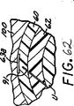
図53−63を参照すると、図32−52のグリップの改良品が示されている。図53−55において、ノズル、あるいはブラシ等により継ぎ目91の全体を覆って被覆された、ホットなポリウレタン96が示されている。図56−58において、ノズル、あるいはブラシ等により凹部95を充填しているホットなポリウレタン96が示されている。別の実施態様において、ホットなポリウレタン96は継ぎ目に沿ったポリウレタン層の両端部の間に注入される。図59は、加熱圧板100を有する第三のモールドM3を示し、モールドM3の下側はグリップのポリウレタン層60の表面にエンボス加工される、摩擦増強パターンの部分63aを備えて形成される。加熱圧板100は、ポリウレタンデポジット96が未だホットである間に継ぎ目の領域の全体を覆うポリウレタン層60の外表面に対し押圧される。この配列によって、継ぎ目91の外側のポリウレタン層60の外部領域は、図60の摩擦増強部分63aを備えて形成され、それによって部分63aは以前にグリップGのポリウレタン層60に成形された摩擦増強パターン63に融け込む。図63は、ゴルフクラブGCのシャフト55の上に配置され且つシャフト55に接着された、融け込んだ摩擦増強パターン63を備えるそのようなグリップG−5を示す。あるいは、別の実施態様において、加熱圧板100は、最初に被覆することなしに、ホットなポリウレタン96を備える継ぎ目の中にあるいは沿って摩擦増強パターンを形成するために剥き出しの継ぎ目に対し促される。摩擦増強パターン63を直接継ぎ目91にプレスすることは、製造工程の工程を解消しひいては製造価格を低減する。
Referring to FIGS. 53-63, an improved version of the grip of FIGS. 32-52 is shown. 53-55,
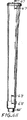
図64−73を参照すると、従来のパターPと共に使用するための、ポリウレタン-EVA製単一パネルのグリップPGが示されている。グリップPGは、弾力性のある下地スリーブUP(図.64−68)を含み、そのスリーブUPは環状形状ではないことを除いて、前述の下地スリーブUにほぼ類似している。代わりに、下地スリーブUPの正面98は、一般使用の殆どのパターの設計図に従って平坦な形状である。下地スリーブUPは、前述の単一パネルSに類似のポリウレタン−EVA形態の単一パネルSPを収納すると分る。そのような単一パネルSPは、二つのグリップの同一部分は同一の参照符号で印付けられている、ポリウレタン-EVA製単一パネルのグリップG-1−G-5のパネルPに関し、前述と同一の方法で下地スリーブの周囲に巻き付けられ、また接着される。同様に、もしも歯部94´が、チャネル95´を創生するために使用されるならば、チャネル95´はそのままにおかれるか、あるいはホットなポリウレタン96´で充填され、またそのままにおかれるか、あるいはブラシ等97´でバフ研磨される(この中で開示されるグリップの可能な改良の事例のために図38−63を参照)。一つの実施態様において、パネルSPは図69に示されるように平滑である。パターPは一般に、他のクラブに伴う一般に長いスイングに比較して短くなったパット・スイングのため弱い力を受けるので、パター用グリップPGは、摩擦増強パターン63´を必要としないと思われる。あるいは、パネルSPは、ロゴ114´などのより小さな加熱エンボス加工され可視化された印(示されていない)、あるいは加熱エンボス加工された摩擦増強パターン63´(示されていない)、あるいはインクで可視化された印118´(示されていない)、あるいはパネル118´の全長の大部分に延びているより大きな加熱エンボス加工されたパターン(示されていない)、あるいはそれらの組合せもしくは改良のいずれかを組込むと良い。
Referring to FIGS. 64-73, a polyurethane-EVA single panel grip PG for use with a conventional putter P is shown. The grip PG includes a resilient base sleeve UP (FIGS. 64-68), which is substantially similar to the base sleeve U described above, except that the sleeve UP is not annular. Instead, the
本発明を具体化するグリップの外表面は、表面を保護し、表面に粘着性を加え、表面の耐久性を増大するために、ブラシ、あるいはノズル、あるいはスプレーヤ等の手段によりポリマ物質、好ましくはポリウレタンの薄い層(示されていない)を用いて被覆されると良いことが分る。 The outer surface of the grip embodying the present invention is a polymeric material, preferably by means of a brush, nozzle or sprayer, etc., to protect the surface, add tackiness to the surface and increase the durability of the surface. It will be appreciated that a thin layer of polyurethane (not shown) may be used for coating.
本発明のゴルフクラブ用グリップは、従来の巻き付けられたグリップと単一パネルのグリップを上回るいくつかの利点を備えている。さらに、そのようなグリップは、プロフェッショナルと低いハンディキャップのゴルファによく知られている成型され一体化されたグリップの外観を有する。そのようなゴルファの幾人かは、従来的でない巻き付けられたクラブを使用したがらないが、このグリップが、巻き付けられたグリップの衝撃吸収と粘着の特性を与えるため、本発明の一体構造のグリップを用いてプレーするのをいとわないであろう。さらに、内層としてEVAなどのポリマ物質を使用することは、クラブのグリップを軽量化し、またクラブのグリップ中への湿気の必要以上の吸収を阻止する。 The golf club grip of the present invention has several advantages over conventional wrapped grips and single panel grips. In addition, such grips have the appearance of a molded and integrated grip familiar to professionals and low handicap golfers. Some such golfers are reluctant to use a non-conventional wound club, but the grip provides the shock absorbing and sticking properties of the wound grip so that the monolithic grip of the present invention Willing to play with Further, the use of a polymer material such as EVA as the inner layer reduces the club grip and prevents excessive absorption of moisture into the club grip.
様々な改良と変更が、本発明の精神から逸脱することなしに前述の詳細説明に関して実施される可能性がある。 Various modifications and changes may be made with respect to the foregoing detailed description without departing from the spirit of the invention.
Claims (17)
ゴルフクラブの握り部を受容するように形成された第一端部と第二端部とを有する弾力性のある下地スリーブであって、第一端部と第二端部との間で延びる長手軸線を画成する下地スリーブと、
EVA製内層に接合されたポリウレタン製外層を含む単一パネルであって、前記弾力性のある下地スリーブの外部形状に対応した形状を有し、前記下地スリーブの周囲に巻き付けられると共に接着され、前記内層の内面から前記外層の外面まで延びる長手方向継ぎ目を形成するように互いに当接する前記パネルの側縁部を備える、単一パネルとを具備し、
前記継ぎ目は、最初は前記外層のポリウレタンから分離されているポリウレタンのデポジットにより被覆される、グリップ。A grip for a grip part of a golf club,
A resilient base sleeve having a first end and a second end configured to receive a grip portion of a golf club, the length extending between the first end and the second end A base sleeve that defines an axis; and
A single panel comprising a polyurethane outer layer joined to an EVA inner layer, having a shape corresponding to the outer shape of the resilient base sleeve, wound and bonded around the base sleeve, A single panel comprising side edges of the panels abutting each other to form a longitudinal seam extending from the inner surface of the inner layer to the outer surface of the outer layer;
The grip is covered by a polyurethane deposit that is initially separated from the polyurethane of the outer layer .
ゴルフクラブの握り部を受容するように形成された第一端部と第二端部とを有する弾力性のある下地スリーブであって、第一端部と第二端部との間で延びる長手軸線を画成する下地スリーブを提供する工程と、
EVA製内層に接合されたポリウレタン製外層を含み且つ前記弾力性のあるスリーブの外部形状に対応した形状を有する単一パネルを提供する工程と、
前記単一パネルを前記下地スリーブの周囲に巻き付けて該下地スリーブに接着する工程と、
前記内層の内面から前記外層の外面まで延びる長手方向継ぎ目を形成するように、前記パネルの両側縁部を互いに当接させる工程と、
前記継ぎ目を、最初は前記外層のポリウレタンから分離されているポリウレタンのデポジットで被覆する工程とを具備する、製造方法。A method of manufacturing a grip for a grip portion of a golf club,
A resilient base sleeve having a first end and a second end configured to receive a grip portion of a golf club, the length extending between the first end and the second end Providing a base sleeve defining an axis;
Providing a single panel comprising a polyurethane outer layer joined to an EVA inner layer and having a shape corresponding to the outer shape of the resilient sleeve;
Wrapping the single panel around the base sleeve and bonding to the base sleeve;
Bringing both side edges of the panel into contact with each other to form a longitudinal seam extending from the inner surface of the inner layer to the outer surface of the outer layer;
Coating the seam with a polyurethane deposit initially separated from the polyurethane of the outer layer .
Applications Claiming Priority (2)
| Application Number | Priority Date | Filing Date | Title |
|---|---|---|---|
| US57260404P | 2004-05-19 | 2004-05-19 | |
| PCT/US2005/017204 WO2005115563A1 (en) | 2004-05-19 | 2005-05-17 | Single panel golf club grip with eva inside layer |
Publications (3)
| Publication Number | Publication Date |
|---|---|
| JP2007527302A JP2007527302A (en) | 2007-09-27 |
| JP2007527302A5 JP2007527302A5 (en) | 2009-06-25 |
| JP4662975B2 true JP4662975B2 (en) | 2011-03-30 |
Family
ID=35450679
Family Applications (1)
| Application Number | Title | Priority Date | Filing Date |
|---|---|---|---|
| JP2007502127A Expired - Fee Related JP4662975B2 (en) | 2004-05-19 | 2005-05-17 | Single panel golf club grip with EVA inner layer |
Country Status (3)
| Country | Link |
|---|---|
| JP (1) | JP4662975B2 (en) |
| CN (1) | CN100488587C (en) |
| WO (1) | WO2005115563A1 (en) |
Families Citing this family (8)
| Publication number | Priority date | Publication date | Assignee | Title |
|---|---|---|---|---|
| US7186189B2 (en) | 2005-07-01 | 2007-03-06 | Ben Huang | Panel grip with modified seam |
| US7347792B2 (en) | 2006-05-22 | 2008-03-25 | Ben Huang | Decorative golf club grip |
| US7862445B2 (en) | 2007-03-21 | 2011-01-04 | Ben Huang | Grip having a stabilized gripping surface |
| JP2010246913A (en) * | 2009-04-10 | 2010-11-04 | Ben Huang | Super-lightweight grip for golf club or the like |
| US9661833B2 (en) | 2009-04-10 | 2017-05-30 | Ben Huang | Multi-layered grip |
| US8518505B2 (en) * | 2009-04-10 | 2013-08-27 | Ben Huang | Multi-layered grip |
| US8323433B1 (en) * | 2011-08-26 | 2012-12-04 | Eaton Corporation | Method of making a cord style flexible golf grip |
| US10653124B2 (en) | 2017-05-03 | 2020-05-19 | Winn Incorporated | Reel component and method of manufacturing same |
Citations (9)
| Publication number | Priority date | Publication date | Assignee | Title |
|---|---|---|---|---|
| US2221421A (en) * | 1938-11-25 | 1940-11-12 | Spalding A G & Bros Inc | Athletic implement and method of making the same |
| JPH0381404U (en) * | 1989-12-12 | 1991-08-20 | ||
| JPH0387157U (en) * | 1989-12-22 | 1991-09-04 | ||
| JPH0397366U (en) * | 1990-01-22 | 1991-10-07 | ||
| US5730669A (en) * | 1991-01-14 | 1998-03-24 | Huang; Ben | Handle grip and method of making same |
| US20040029645A1 (en) * | 2002-08-08 | 2004-02-12 | Chen Sam H. | Lip edge grip tape and method of making a gripping surface |
| JP2004049900A (en) * | 2002-06-11 | 2004-02-19 | Ben Huang | Spirally wrapped golf club grip |
| US20040185958A1 (en) * | 2003-03-18 | 2004-09-23 | Ben Huang | Single panel golf club grip |
| US6843732B1 (en) * | 2003-12-23 | 2005-01-18 | Ben Huang | Multi-segment single panel grip |
Family Cites Families (4)
| Publication number | Priority date | Publication date | Assignee | Title |
|---|---|---|---|---|
| US1890037A (en) * | 1930-11-21 | 1932-12-06 | Herbert B Johnson | Rubber covered article |
| GB979242A (en) * | 1963-01-03 | 1965-01-01 | John Henry Onions | Improvements relating to grips for the handles or shafts of ball striking devices for use in games |
| US6036607A (en) * | 1998-03-02 | 2000-03-14 | Finegan; Christopher H. | Adjustable grip |
| AUPP442798A0 (en) * | 1998-07-01 | 1998-07-23 | Grip Master Company Pty Ltd, The | A grip for a handle or shaft |
-
2005
- 2005-05-17 JP JP2007502127A patent/JP4662975B2/en not_active Expired - Fee Related
- 2005-05-17 CN CNB2005800000585A patent/CN100488587C/en not_active Expired - Fee Related
- 2005-05-17 WO PCT/US2005/017204 patent/WO2005115563A1/en active Application Filing
Patent Citations (9)
| Publication number | Priority date | Publication date | Assignee | Title |
|---|---|---|---|---|
| US2221421A (en) * | 1938-11-25 | 1940-11-12 | Spalding A G & Bros Inc | Athletic implement and method of making the same |
| JPH0381404U (en) * | 1989-12-12 | 1991-08-20 | ||
| JPH0387157U (en) * | 1989-12-22 | 1991-09-04 | ||
| JPH0397366U (en) * | 1990-01-22 | 1991-10-07 | ||
| US5730669A (en) * | 1991-01-14 | 1998-03-24 | Huang; Ben | Handle grip and method of making same |
| JP2004049900A (en) * | 2002-06-11 | 2004-02-19 | Ben Huang | Spirally wrapped golf club grip |
| US20040029645A1 (en) * | 2002-08-08 | 2004-02-12 | Chen Sam H. | Lip edge grip tape and method of making a gripping surface |
| US20040185958A1 (en) * | 2003-03-18 | 2004-09-23 | Ben Huang | Single panel golf club grip |
| US6843732B1 (en) * | 2003-12-23 | 2005-01-18 | Ben Huang | Multi-segment single panel grip |
Also Published As
| Publication number | Publication date |
|---|---|
| CN1798592A (en) | 2006-07-05 |
| WO2005115563A1 (en) | 2005-12-08 |
| CN100488587C (en) | 2009-05-20 |
| JP2007527302A (en) | 2007-09-27 |
Similar Documents
| Publication | Publication Date | Title |
|---|---|---|
| US7585230B2 (en) | Single panel golf club grip with EVA inside layer | |
| JP4394658B2 (en) | Panel grip with deformed seams | |
| US7470199B2 (en) | Single panel golf club grip | |
| JP4382638B2 (en) | Grip for grip part of golf club | |
| JP4662975B2 (en) | Single panel golf club grip with EVA inner layer | |
| TWI374765B (en) | Panel grip with cut-outs and inserts | |
| US6676534B2 (en) | Composite grip for golf clubs | |
| JP2007527302A5 (en) | ||
| US6641488B2 (en) | All-weather shock absorbing grip for golf clubs and the like | |
| JP2010522047A (en) | Grip with modified gripping surface |
Legal Events
| Date | Code | Title | Description |
|---|---|---|---|
| A131 | Notification of reasons for refusal |
Free format text: JAPANESE INTERMEDIATE CODE: A131 Effective date: 20081111 |
|
| A601 | Written request for extension of time |
Free format text: JAPANESE INTERMEDIATE CODE: A601 Effective date: 20090210 |
|
| A602 | Written permission of extension of time |
Free format text: JAPANESE INTERMEDIATE CODE: A602 Effective date: 20090218 |
|
| A524 | Written submission of copy of amendment under section 19 (pct) |
Free format text: JAPANESE INTERMEDIATE CODE: A524 Effective date: 20090511 |
|
| A131 | Notification of reasons for refusal |
Free format text: JAPANESE INTERMEDIATE CODE: A131 Effective date: 20090623 |
|
| A601 | Written request for extension of time |
Free format text: JAPANESE INTERMEDIATE CODE: A601 Effective date: 20090918 |
|
| A602 | Written permission of extension of time |
Free format text: JAPANESE INTERMEDIATE CODE: A602 Effective date: 20090930 |
|
| A521 | Written amendment |
Free format text: JAPANESE INTERMEDIATE CODE: A523 Effective date: 20091222 |
|
| A131 | Notification of reasons for refusal |
Free format text: JAPANESE INTERMEDIATE CODE: A131 Effective date: 20100223 |
|
| A601 | Written request for extension of time |
Free format text: JAPANESE INTERMEDIATE CODE: A601 Effective date: 20100520 |
|
| A602 | Written permission of extension of time |
Free format text: JAPANESE INTERMEDIATE CODE: A602 Effective date: 20100527 |
|
| TRDD | Decision of grant or rejection written | ||
| A01 | Written decision to grant a patent or to grant a registration (utility model) |
Free format text: JAPANESE INTERMEDIATE CODE: A01 Effective date: 20101130 |
|
| A01 | Written decision to grant a patent or to grant a registration (utility model) |
Free format text: JAPANESE INTERMEDIATE CODE: A01 |
|
| A61 | First payment of annual fees (during grant procedure) |
Free format text: JAPANESE INTERMEDIATE CODE: A61 Effective date: 20110104 |
|
| R150 | Certificate of patent or registration of utility model |
Free format text: JAPANESE INTERMEDIATE CODE: R150 |
|
| FPAY | Renewal fee payment (event date is renewal date of database) |
Free format text: PAYMENT UNTIL: 20140114 Year of fee payment: 3 |
|
| R250 | Receipt of annual fees |
Free format text: JAPANESE INTERMEDIATE CODE: R250 |
|
| R250 | Receipt of annual fees |
Free format text: JAPANESE INTERMEDIATE CODE: R250 |
|
| R250 | Receipt of annual fees |
Free format text: JAPANESE INTERMEDIATE CODE: R250 |
|
| LAPS | Cancellation because of no payment of annual fees |