JP4662151B2 - Filler for solar cell module, solar cell module using the same, and method for producing filler for solar cell module - Google Patents
Filler for solar cell module, solar cell module using the same, and method for producing filler for solar cell module Download PDFInfo
- Publication number
- JP4662151B2 JP4662151B2 JP2005344050A JP2005344050A JP4662151B2 JP 4662151 B2 JP4662151 B2 JP 4662151B2 JP 2005344050 A JP2005344050 A JP 2005344050A JP 2005344050 A JP2005344050 A JP 2005344050A JP 4662151 B2 JP4662151 B2 JP 4662151B2
- Authority
- JP
- Japan
- Prior art keywords
- solar cell
- filler
- polyethylene
- cell module
- density
- Prior art date
- Legal status (The legal status is an assumption and is not a legal conclusion. Google has not performed a legal analysis and makes no representation as to the accuracy of the status listed.)
- Active
Links
- 239000000945 filler Substances 0.000 title claims description 168
- 238000004519 manufacturing process Methods 0.000 title claims description 22
- -1 unsaturated silane compound Chemical class 0.000 claims description 112
- 239000004698 Polyethylene Substances 0.000 claims description 88
- 229920000573 polyethylene Polymers 0.000 claims description 88
- 229920005989 resin Polymers 0.000 claims description 76
- 239000011347 resin Substances 0.000 claims description 76
- 239000004594 Masterbatch (MB) Substances 0.000 claims description 62
- 238000006116 polymerization reaction Methods 0.000 claims description 29
- 239000012760 heat stabilizer Substances 0.000 claims description 28
- 229920001526 metallocene linear low density polyethylene Polymers 0.000 claims description 27
- 239000004611 light stabiliser Substances 0.000 claims description 24
- 239000006097 ultraviolet radiation absorber Substances 0.000 claims description 20
- 238000002844 melting Methods 0.000 claims description 18
- 230000008018 melting Effects 0.000 claims description 18
- 230000000379 polymerizing effect Effects 0.000 claims description 10
- 238000010438 heat treatment Methods 0.000 claims description 7
- 239000006096 absorbing agent Substances 0.000 claims description 4
- 210000004027 cell Anatomy 0.000 description 195
- 238000000034 method Methods 0.000 description 33
- 239000000758 substrate Substances 0.000 description 30
- 238000002360 preparation method Methods 0.000 description 18
- 239000000654 additive Substances 0.000 description 17
- 230000000996 additive effect Effects 0.000 description 16
- 239000011521 glass Substances 0.000 description 16
- 238000012360 testing method Methods 0.000 description 14
- 230000008859 change Effects 0.000 description 12
- 230000000052 comparative effect Effects 0.000 description 10
- 150000001412 amines Chemical class 0.000 description 9
- 230000001681 protective effect Effects 0.000 description 9
- QRUDEWIWKLJBPS-UHFFFAOYSA-N benzotriazole Chemical compound C1=CC=C2N[N][N]C2=C1 QRUDEWIWKLJBPS-UHFFFAOYSA-N 0.000 description 8
- 239000012964 benzotriazole Substances 0.000 description 8
- 239000000843 powder Substances 0.000 description 8
- OAICVXFJPJFONN-UHFFFAOYSA-N Phosphorus Chemical compound [P] OAICVXFJPJFONN-UHFFFAOYSA-N 0.000 description 7
- 238000009826 distribution Methods 0.000 description 7
- 239000005038 ethylene vinyl acetate Substances 0.000 description 7
- 238000005259 measurement Methods 0.000 description 7
- 229910052698 phosphorus Inorganic materials 0.000 description 7
- 239000011574 phosphorus Substances 0.000 description 7
- 229920001200 poly(ethylene-vinyl acetate) Polymers 0.000 description 7
- 238000010298 pulverizing process Methods 0.000 description 7
- 150000003254 radicals Chemical class 0.000 description 7
- 238000000862 absorption spectrum Methods 0.000 description 6
- 239000000470 constituent Substances 0.000 description 6
- 229920000092 linear low density polyethylene Polymers 0.000 description 6
- 239000004707 linear low-density polyethylene Substances 0.000 description 6
- 239000002245 particle Substances 0.000 description 6
- 229910000077 silane Inorganic materials 0.000 description 6
- 238000002425 crystallisation Methods 0.000 description 5
- 230000008025 crystallization Effects 0.000 description 5
- NKSJNEHGWDZZQF-UHFFFAOYSA-N ethenyl(trimethoxy)silane Chemical compound CO[Si](OC)(OC)C=C NKSJNEHGWDZZQF-UHFFFAOYSA-N 0.000 description 5
- 239000010408 film Substances 0.000 description 5
- 238000010030 laminating Methods 0.000 description 5
- 238000003475 lamination Methods 0.000 description 5
- 239000000155 melt Substances 0.000 description 5
- XMNIXWIUMCBBBL-UHFFFAOYSA-N 2-(2-phenylpropan-2-ylperoxy)propan-2-ylbenzene Chemical compound C=1C=CC=CC=1C(C)(C)OOC(C)(C)C1=CC=CC=C1 XMNIXWIUMCBBBL-UHFFFAOYSA-N 0.000 description 4
- 238000001816 cooling Methods 0.000 description 4
- 238000000605 extraction Methods 0.000 description 4
- 238000002156 mixing Methods 0.000 description 4
- 229910021420 polycrystalline silicon Inorganic materials 0.000 description 4
- 229920002620 polyvinyl fluoride Polymers 0.000 description 4
- 238000010248 power generation Methods 0.000 description 4
- 238000012545 processing Methods 0.000 description 4
- 238000002834 transmittance Methods 0.000 description 4
- ZWEHNKRNPOVVGH-UHFFFAOYSA-N 2-Butanone Chemical compound CCC(C)=O ZWEHNKRNPOVVGH-UHFFFAOYSA-N 0.000 description 3
- BLRPTPMANUNPDV-UHFFFAOYSA-N Silane Chemical compound [SiH4] BLRPTPMANUNPDV-UHFFFAOYSA-N 0.000 description 3
- XTXRWKRVRITETP-UHFFFAOYSA-N Vinyl acetate Chemical compound CC(=O)OC=C XTXRWKRVRITETP-UHFFFAOYSA-N 0.000 description 3
- 229910021417 amorphous silicon Inorganic materials 0.000 description 3
- 239000007809 chemical reaction catalyst Substances 0.000 description 3
- 239000003795 chemical substances by application Substances 0.000 description 3
- 150000001875 compounds Chemical class 0.000 description 3
- 229910021419 crystalline silicon Inorganic materials 0.000 description 3
- 230000000694 effects Effects 0.000 description 3
- 239000007789 gas Substances 0.000 description 3
- 239000000463 material Substances 0.000 description 3
- 229910052751 metal Inorganic materials 0.000 description 3
- 239000002184 metal Substances 0.000 description 3
- 238000005453 pelletization Methods 0.000 description 3
- 238000004451 qualitative analysis Methods 0.000 description 3
- 238000004445 quantitative analysis Methods 0.000 description 3
- 239000004065 semiconductor Substances 0.000 description 3
- 239000010409 thin film Substances 0.000 description 3
- OZAIFHULBGXAKX-UHFFFAOYSA-N 2-(2-cyanopropan-2-yldiazenyl)-2-methylpropanenitrile Chemical compound N#CC(C)(C)N=NC(C)(C)C#N OZAIFHULBGXAKX-UHFFFAOYSA-N 0.000 description 2
- 239000004925 Acrylic resin Substances 0.000 description 2
- 229920000178 Acrylic resin Polymers 0.000 description 2
- YCKRFDGAMUMZLT-UHFFFAOYSA-N Fluorine atom Chemical compound [F] YCKRFDGAMUMZLT-UHFFFAOYSA-N 0.000 description 2
- 238000004566 IR spectroscopy Methods 0.000 description 2
- GPXJNWSHGFTCBW-UHFFFAOYSA-N Indium phosphide Chemical compound [In]#P GPXJNWSHGFTCBW-UHFFFAOYSA-N 0.000 description 2
- CTQNGGLPUBDAKN-UHFFFAOYSA-N O-Xylene Chemical group CC1=CC=CC=C1C CTQNGGLPUBDAKN-UHFFFAOYSA-N 0.000 description 2
- XLOMVQKBTHCTTD-UHFFFAOYSA-N Zinc monoxide Chemical compound [Zn]=O XLOMVQKBTHCTTD-UHFFFAOYSA-N 0.000 description 2
- MCMNRKCIXSYSNV-UHFFFAOYSA-N Zirconium dioxide Chemical compound O=[Zr]=O MCMNRKCIXSYSNV-UHFFFAOYSA-N 0.000 description 2
- 238000010521 absorption reaction Methods 0.000 description 2
- 239000000853 adhesive Substances 0.000 description 2
- 230000001070 adhesive effect Effects 0.000 description 2
- 229910052782 aluminium Inorganic materials 0.000 description 2
- XAGFODPZIPBFFR-UHFFFAOYSA-N aluminium Chemical compound [Al] XAGFODPZIPBFFR-UHFFFAOYSA-N 0.000 description 2
- 239000012298 atmosphere Substances 0.000 description 2
- 230000008901 benefit Effects 0.000 description 2
- RPPBZEBXAAZZJH-UHFFFAOYSA-N cadmium telluride Chemical compound [Te]=[Cd] RPPBZEBXAAZZJH-UHFFFAOYSA-N 0.000 description 2
- 239000003054 catalyst Substances 0.000 description 2
- 125000004122 cyclic group Chemical group 0.000 description 2
- 229910052731 fluorine Inorganic materials 0.000 description 2
- 239000011737 fluorine Substances 0.000 description 2
- 229920001903 high density polyethylene Polymers 0.000 description 2
- 239000004700 high-density polyethylene Substances 0.000 description 2
- 230000001771 impaired effect Effects 0.000 description 2
- 238000009434 installation Methods 0.000 description 2
- 150000002596 lactones Chemical class 0.000 description 2
- 239000005340 laminated glass Substances 0.000 description 2
- 239000007788 liquid Substances 0.000 description 2
- 239000012968 metallocene catalyst Substances 0.000 description 2
- 229910021421 monocrystalline silicon Inorganic materials 0.000 description 2
- 238000000465 moulding Methods 0.000 description 2
- 150000002978 peroxides Chemical class 0.000 description 2
- 238000001782 photodegradation Methods 0.000 description 2
- 229920003023 plastic Polymers 0.000 description 2
- 239000004033 plastic Substances 0.000 description 2
- 229920006122 polyamide resin Polymers 0.000 description 2
- 229920005668 polycarbonate resin Polymers 0.000 description 2
- 239000004431 polycarbonate resin Substances 0.000 description 2
- 229920001225 polyester resin Polymers 0.000 description 2
- 239000004645 polyester resin Substances 0.000 description 2
- 229920013716 polyethylene resin Polymers 0.000 description 2
- 229920005672 polyolefin resin Polymers 0.000 description 2
- 230000002265 prevention Effects 0.000 description 2
- 230000008569 process Effects 0.000 description 2
- 238000010992 reflux Methods 0.000 description 2
- 239000002904 solvent Substances 0.000 description 2
- 239000012085 test solution Substances 0.000 description 2
- 239000003017 thermal stabilizer Substances 0.000 description 2
- WRXCBRHBHGNNQA-UHFFFAOYSA-N (2,4-dichlorobenzoyl) 2,4-dichlorobenzenecarboperoxoate Chemical compound ClC1=CC(Cl)=CC=C1C(=O)OOC(=O)C1=CC=C(Cl)C=C1Cl WRXCBRHBHGNNQA-UHFFFAOYSA-N 0.000 description 1
- ZICNIEOYWVIEQJ-UHFFFAOYSA-N (2-methylbenzoyl) 2-methylbenzenecarboperoxoate Chemical compound CC1=CC=CC=C1C(=O)OOC(=O)C1=CC=CC=C1C ZICNIEOYWVIEQJ-UHFFFAOYSA-N 0.000 description 1
- FVQMJJQUGGVLEP-UHFFFAOYSA-N (2-methylpropan-2-yl)oxy 2-ethylhexaneperoxoate Chemical compound CCCCC(CC)C(=O)OOOC(C)(C)C FVQMJJQUGGVLEP-UHFFFAOYSA-N 0.000 description 1
- QEQBMZQFDDDTPN-UHFFFAOYSA-N (2-methylpropan-2-yl)oxy benzenecarboperoxoate Chemical compound CC(C)(C)OOOC(=O)C1=CC=CC=C1 QEQBMZQFDDDTPN-UHFFFAOYSA-N 0.000 description 1
- KDGNCLDCOVTOCS-UHFFFAOYSA-N (2-methylpropan-2-yl)oxy propan-2-yl carbonate Chemical compound CC(C)OC(=O)OOC(C)(C)C KDGNCLDCOVTOCS-UHFFFAOYSA-N 0.000 description 1
- RIPYNJLMMFGZSX-UHFFFAOYSA-N (5-benzoylperoxy-2,5-dimethylhexan-2-yl) benzenecarboperoxoate Chemical compound C=1C=CC=CC=1C(=O)OOC(C)(C)CCC(C)(C)OOC(=O)C1=CC=CC=C1 RIPYNJLMMFGZSX-UHFFFAOYSA-N 0.000 description 1
- UICXTANXZJJIBC-UHFFFAOYSA-N 1-(1-hydroperoxycyclohexyl)peroxycyclohexan-1-ol Chemical compound C1CCCCC1(O)OOC1(OO)CCCCC1 UICXTANXZJJIBC-UHFFFAOYSA-N 0.000 description 1
- DMWVYCCGCQPJEA-UHFFFAOYSA-N 2,5-bis(tert-butylperoxy)-2,5-dimethylhexane Chemical compound CC(C)(C)OOC(C)(C)CCC(C)(C)OOC(C)(C)C DMWVYCCGCQPJEA-UHFFFAOYSA-N 0.000 description 1
- JGBAASVQPMTVHO-UHFFFAOYSA-N 2,5-dihydroperoxy-2,5-dimethylhexane Chemical compound OOC(C)(C)CCC(C)(C)OO JGBAASVQPMTVHO-UHFFFAOYSA-N 0.000 description 1
- WYGWHHGCAGTUCH-UHFFFAOYSA-N 2-[(2-cyano-4-methylpentan-2-yl)diazenyl]-2,4-dimethylpentanenitrile Chemical compound CC(C)CC(C)(C#N)N=NC(C)(C#N)CC(C)C WYGWHHGCAGTUCH-UHFFFAOYSA-N 0.000 description 1
- BIISIZOQPWZPPS-UHFFFAOYSA-N 2-tert-butylperoxypropan-2-ylbenzene Chemical compound CC(C)(C)OOC(C)(C)C1=CC=CC=C1 BIISIZOQPWZPPS-UHFFFAOYSA-N 0.000 description 1
- NLHHRLWOUZZQLW-UHFFFAOYSA-N Acrylonitrile Chemical compound C=CC#N NLHHRLWOUZZQLW-UHFFFAOYSA-N 0.000 description 1
- JBRZTFJDHDCESZ-UHFFFAOYSA-N AsGa Chemical compound [As]#[Ga] JBRZTFJDHDCESZ-UHFFFAOYSA-N 0.000 description 1
- 239000004342 Benzoyl peroxide Substances 0.000 description 1
- OMPJBNCRMGITSC-UHFFFAOYSA-N Benzoylperoxide Chemical compound C=1C=CC=CC=1C(=O)OOC(=O)C1=CC=CC=C1 OMPJBNCRMGITSC-UHFFFAOYSA-N 0.000 description 1
- AUGCRDPUJKRPGA-UHFFFAOYSA-N CC(C)(C)C1=CC(C(C)(C)C)=C(C(C(CO)(CO)CO)(C2=C(C(C)(C)C)C=C(C(C)(C)C)C=C2)O)C=C1.OP(O)OP(O)O.P Chemical compound CC(C)(C)C1=CC(C(C)(C)C)=C(C(C(CO)(CO)CO)(C2=C(C(C)(C)C)C=C(C(C)(C)C)C=C2)O)C=C1.OP(O)OP(O)O.P AUGCRDPUJKRPGA-UHFFFAOYSA-N 0.000 description 1
- LCRNRCXIKZEMSB-UHFFFAOYSA-N CCCCOOC(=O)C1=CC=CC=C1C(O)=O Chemical compound CCCCOOC(=O)C1=CC=CC=C1C(O)=O LCRNRCXIKZEMSB-UHFFFAOYSA-N 0.000 description 1
- UFHFLCQGNIYNRP-UHFFFAOYSA-N Hydrogen Chemical compound [H][H] UFHFLCQGNIYNRP-UHFFFAOYSA-N 0.000 description 1
- ISWSIDIOOBJBQZ-UHFFFAOYSA-N Phenol Chemical compound OC1=CC=CC=C1 ISWSIDIOOBJBQZ-UHFFFAOYSA-N 0.000 description 1
- JKIJEFPNVSHHEI-UHFFFAOYSA-N Phenol, 2,4-bis(1,1-dimethylethyl)-, phosphite (3:1) Chemical compound CC(C)(C)C1=CC(C(C)(C)C)=CC=C1OP(OC=1C(=CC(=CC=1)C(C)(C)C)C(C)(C)C)OC1=CC=C(C(C)(C)C)C=C1C(C)(C)C JKIJEFPNVSHHEI-UHFFFAOYSA-N 0.000 description 1
- 206010037660 Pyrexia Diseases 0.000 description 1
- NINIDFKCEFEMDL-UHFFFAOYSA-N Sulfur Chemical compound [S] NINIDFKCEFEMDL-UHFFFAOYSA-N 0.000 description 1
- GWEVSGVZZGPLCZ-UHFFFAOYSA-N Titan oxide Chemical compound O=[Ti]=O GWEVSGVZZGPLCZ-UHFFFAOYSA-N 0.000 description 1
- BEIOEBMXPVYLRY-UHFFFAOYSA-N [4-[4-bis(2,4-ditert-butylphenoxy)phosphanylphenyl]phenyl]-bis(2,4-ditert-butylphenoxy)phosphane Chemical compound CC(C)(C)C1=CC(C(C)(C)C)=CC=C1OP(C=1C=CC(=CC=1)C=1C=CC(=CC=1)P(OC=1C(=CC(=CC=1)C(C)(C)C)C(C)(C)C)OC=1C(=CC(=CC=1)C(C)(C)C)C(C)(C)C)OC1=CC=C(C(C)(C)C)C=C1C(C)(C)C BEIOEBMXPVYLRY-UHFFFAOYSA-N 0.000 description 1
- KTSFMFGEAAANTF-UHFFFAOYSA-N [Cu].[Se].[Se].[In] Chemical compound [Cu].[Se].[Se].[In] KTSFMFGEAAANTF-UHFFFAOYSA-N 0.000 description 1
- GBTKXRHCGMUSDA-UHFFFAOYSA-N [SiH3]OC(=O)CCC=C Chemical compound [SiH3]OC(=O)CCC=C GBTKXRHCGMUSDA-UHFFFAOYSA-N 0.000 description 1
- NOZAQBYNLKNDRT-UHFFFAOYSA-N [diacetyloxy(ethenyl)silyl] acetate Chemical compound CC(=O)O[Si](OC(C)=O)(OC(C)=O)C=C NOZAQBYNLKNDRT-UHFFFAOYSA-N 0.000 description 1
- AYIGWTYMCHDVTN-UHFFFAOYSA-N [dicarboxy(ethenyl)silyl]formic acid Chemical compound OC(=O)[Si](C=C)(C(O)=O)C(O)=O AYIGWTYMCHDVTN-UHFFFAOYSA-N 0.000 description 1
- PNEYBMLMFCGWSK-UHFFFAOYSA-N aluminium oxide Inorganic materials [O-2].[O-2].[O-2].[Al+3].[Al+3] PNEYBMLMFCGWSK-UHFFFAOYSA-N 0.000 description 1
- 125000000751 azo group Chemical group [*]N=N[*] 0.000 description 1
- 230000004888 barrier function Effects 0.000 description 1
- RWCCWEUUXYIKHB-UHFFFAOYSA-N benzophenone Chemical compound C=1C=CC=CC=1C(=O)C1=CC=CC=C1 RWCCWEUUXYIKHB-UHFFFAOYSA-N 0.000 description 1
- 239000012965 benzophenone Substances 0.000 description 1
- 235000019400 benzoyl peroxide Nutrition 0.000 description 1
- 238000009529 body temperature measurement Methods 0.000 description 1
- 239000007795 chemical reaction product Substances 0.000 description 1
- 229920006026 co-polymeric resin Polymers 0.000 description 1
- 239000002131 composite material Substances 0.000 description 1
- 239000012141 concentrate Substances 0.000 description 1
- 150000004696 coordination complex Chemical class 0.000 description 1
- SPTHWAJJMLCAQF-UHFFFAOYSA-M ctk4f8481 Chemical compound [O-]O.CC(C)C1=CC=CC=C1C(C)C SPTHWAJJMLCAQF-UHFFFAOYSA-M 0.000 description 1
- 230000006866 deterioration Effects 0.000 description 1
- 239000012933 diacyl peroxide Substances 0.000 description 1
- 238000000113 differential scanning calorimetry Methods 0.000 description 1
- BXKDSDJJOVIHMX-UHFFFAOYSA-N edrophonium chloride Chemical compound [Cl-].CC[N+](C)(C)C1=CC=CC(O)=C1 BXKDSDJJOVIHMX-UHFFFAOYSA-N 0.000 description 1
- 238000010292 electrical insulation Methods 0.000 description 1
- 239000008393 encapsulating agent Substances 0.000 description 1
- 230000007613 environmental effect Effects 0.000 description 1
- FWDBOZPQNFPOLF-UHFFFAOYSA-N ethenyl(triethoxy)silane Chemical compound CCO[Si](OCC)(OCC)C=C FWDBOZPQNFPOLF-UHFFFAOYSA-N 0.000 description 1
- PWOZXQOZUNMWKG-UHFFFAOYSA-N ethenyl(tripentoxy)silane Chemical compound CCCCCO[Si](OCCCCC)(OCCCCC)C=C PWOZXQOZUNMWKG-UHFFFAOYSA-N 0.000 description 1
- FEHYCIQPPPQNMI-UHFFFAOYSA-N ethenyl(triphenoxy)silane Chemical compound C=1C=CC=CC=1O[Si](OC=1C=CC=CC=1)(C=C)OC1=CC=CC=C1 FEHYCIQPPPQNMI-UHFFFAOYSA-N 0.000 description 1
- NNBRCHPBPDRPIT-UHFFFAOYSA-N ethenyl(tripropoxy)silane Chemical compound CCCO[Si](OCCC)(OCCC)C=C NNBRCHPBPDRPIT-UHFFFAOYSA-N 0.000 description 1
- MABAWBWRUSBLKQ-UHFFFAOYSA-N ethenyl-tri(propan-2-yloxy)silane Chemical compound CC(C)O[Si](OC(C)C)(OC(C)C)C=C MABAWBWRUSBLKQ-UHFFFAOYSA-N 0.000 description 1
- VYJZXBZFLIBVQA-UHFFFAOYSA-N ethenyl-tris(phenylmethoxy)silane Chemical compound C=1C=CC=CC=1CO[Si](OCC=1C=CC=CC=1)(C=C)OCC1=CC=CC=C1 VYJZXBZFLIBVQA-UHFFFAOYSA-N 0.000 description 1
- 238000011156 evaluation Methods 0.000 description 1
- 238000001125 extrusion Methods 0.000 description 1
- 239000000706 filtrate Substances 0.000 description 1
- 238000001914 filtration Methods 0.000 description 1
- 239000000796 flavoring agent Substances 0.000 description 1
- 239000005329 float glass Substances 0.000 description 1
- 238000005187 foaming Methods 0.000 description 1
- 239000011888 foil Substances 0.000 description 1
- 238000000769 gas chromatography-flame ionisation detection Methods 0.000 description 1
- 238000010559 graft polymerization reaction Methods 0.000 description 1
- 230000005484 gravity Effects 0.000 description 1
- 238000004128 high performance liquid chromatography Methods 0.000 description 1
- BHEPBYXIRTUNPN-UHFFFAOYSA-N hydridophosphorus(.) (triplet) Chemical compound [PH] BHEPBYXIRTUNPN-UHFFFAOYSA-N 0.000 description 1
- 229910052739 hydrogen Inorganic materials 0.000 description 1
- 239000001257 hydrogen Substances 0.000 description 1
- 150000002432 hydroperoxides Chemical class 0.000 description 1
- 238000004898 kneading Methods 0.000 description 1
- 230000007774 longterm Effects 0.000 description 1
- 229920001684 low density polyethylene Polymers 0.000 description 1
- 239000004702 low-density polyethylene Substances 0.000 description 1
- 229920001179 medium density polyethylene Polymers 0.000 description 1
- 239000004701 medium-density polyethylene Substances 0.000 description 1
- 229910021424 microcrystalline silicon Inorganic materials 0.000 description 1
- 239000000203 mixture Substances 0.000 description 1
- 229940078552 o-xylene Drugs 0.000 description 1
- SRSFOMHQIATOFV-UHFFFAOYSA-N octanoyl octaneperoxoate Chemical compound CCCCCCCC(=O)OOC(=O)CCCCCCC SRSFOMHQIATOFV-UHFFFAOYSA-N 0.000 description 1
- 150000001451 organic peroxides Chemical class 0.000 description 1
- 230000001590 oxidative effect Effects 0.000 description 1
- 230000035699 permeability Effects 0.000 description 1
- 238000007539 photo-oxidation reaction Methods 0.000 description 1
- 150000003053 piperidines Chemical class 0.000 description 1
- 239000005020 polyethylene terephthalate Substances 0.000 description 1
- 229920000139 polyethylene terephthalate Polymers 0.000 description 1
- 229920000642 polymer Polymers 0.000 description 1
- 238000007781 pre-processing Methods 0.000 description 1
- 239000000047 product Substances 0.000 description 1
- 230000005855 radiation Effects 0.000 description 1
- 238000010526 radical polymerization reaction Methods 0.000 description 1
- 238000004064 recycling Methods 0.000 description 1
- 230000001105 regulatory effect Effects 0.000 description 1
- 230000003014 reinforcing effect Effects 0.000 description 1
- 238000001226 reprecipitation Methods 0.000 description 1
- YGSDEFSMJLZEOE-UHFFFAOYSA-M salicylate Chemical compound OC1=CC=CC=C1C([O-])=O YGSDEFSMJLZEOE-UHFFFAOYSA-M 0.000 description 1
- 229960001860 salicylate Drugs 0.000 description 1
- 150000004756 silanes Chemical class 0.000 description 1
- 238000010583 slow cooling Methods 0.000 description 1
- 239000000243 solution Substances 0.000 description 1
- 238000001228 spectrum Methods 0.000 description 1
- 238000010183 spectrum analysis Methods 0.000 description 1
- 230000006641 stabilisation Effects 0.000 description 1
- 238000011105 stabilization Methods 0.000 description 1
- 239000000126 substance Substances 0.000 description 1
- 229910052717 sulfur Inorganic materials 0.000 description 1
- 239000011593 sulfur Substances 0.000 description 1
- 238000009864 tensile test Methods 0.000 description 1
- OPQYOFWUFGEMRZ-UHFFFAOYSA-N tert-butyl 2,2-dimethylpropaneperoxoate Chemical compound CC(C)(C)OOC(=O)C(C)(C)C OPQYOFWUFGEMRZ-UHFFFAOYSA-N 0.000 description 1
- ISIJQEHRDSCQIU-UHFFFAOYSA-N tert-butyl 2,7-diazaspiro[4.5]decane-7-carboxylate Chemical compound C1N(C(=O)OC(C)(C)C)CCCC11CNCC1 ISIJQEHRDSCQIU-UHFFFAOYSA-N 0.000 description 1
- 125000000999 tert-butyl group Chemical group [H]C([H])([H])C(*)(C([H])([H])[H])C([H])([H])[H] 0.000 description 1
- 238000010998 test method Methods 0.000 description 1
- OGIDPMRJRNCKJF-UHFFFAOYSA-N titanium oxide Inorganic materials [Ti]=O OGIDPMRJRNCKJF-UHFFFAOYSA-N 0.000 description 1
- 230000007704 transition Effects 0.000 description 1
- SGCFZHOZKKQIBU-UHFFFAOYSA-N tributoxy(ethenyl)silane Chemical compound CCCCO[Si](OCCCC)(OCCCC)C=C SGCFZHOZKKQIBU-UHFFFAOYSA-N 0.000 description 1
- 238000009423 ventilation Methods 0.000 description 1
- 235000021419 vinegar Nutrition 0.000 description 1
- 239000000052 vinegar Substances 0.000 description 1
- 238000004394 yellowing prevention Methods 0.000 description 1
- 239000011787 zinc oxide Substances 0.000 description 1
Images

Classifications
-
- C—CHEMISTRY; METALLURGY
- C08—ORGANIC MACROMOLECULAR COMPOUNDS; THEIR PREPARATION OR CHEMICAL WORKING-UP; COMPOSITIONS BASED THEREON
- C08J—WORKING-UP; GENERAL PROCESSES OF COMPOUNDING; AFTER-TREATMENT NOT COVERED BY SUBCLASSES C08B, C08C, C08F, C08G or C08H
- C08J3/00—Processes of treating or compounding macromolecular substances
- C08J3/20—Compounding polymers with additives, e.g. colouring
- C08J3/22—Compounding polymers with additives, e.g. colouring using masterbatch techniques
- C08J3/226—Compounding polymers with additives, e.g. colouring using masterbatch techniques using a polymer as a carrier
-
- H—ELECTRICITY
- H01—ELECTRIC ELEMENTS
- H01L—SEMICONDUCTOR DEVICES NOT COVERED BY CLASS H10
- H01L31/00—Semiconductor devices sensitive to infrared radiation, light, electromagnetic radiation of shorter wavelength or corpuscular radiation and specially adapted either for the conversion of the energy of such radiation into electrical energy or for the control of electrical energy by such radiation; Processes or apparatus specially adapted for the manufacture or treatment thereof or of parts thereof; Details thereof
- H01L31/04—Semiconductor devices sensitive to infrared radiation, light, electromagnetic radiation of shorter wavelength or corpuscular radiation and specially adapted either for the conversion of the energy of such radiation into electrical energy or for the control of electrical energy by such radiation; Processes or apparatus specially adapted for the manufacture or treatment thereof or of parts thereof; Details thereof adapted as photovoltaic [PV] conversion devices
- H01L31/042—PV modules or arrays of single PV cells
- H01L31/048—Encapsulation of modules
-
- C—CHEMISTRY; METALLURGY
- C08—ORGANIC MACROMOLECULAR COMPOUNDS; THEIR PREPARATION OR CHEMICAL WORKING-UP; COMPOSITIONS BASED THEREON
- C08F—MACROMOLECULAR COMPOUNDS OBTAINED BY REACTIONS ONLY INVOLVING CARBON-TO-CARBON UNSATURATED BONDS
- C08F255/00—Macromolecular compounds obtained by polymerising monomers on to polymers of hydrocarbons as defined in group C08F10/00
- C08F255/02—Macromolecular compounds obtained by polymerising monomers on to polymers of hydrocarbons as defined in group C08F10/00 on to polymers of olefins having two or three carbon atoms
-
- C—CHEMISTRY; METALLURGY
- C08—ORGANIC MACROMOLECULAR COMPOUNDS; THEIR PREPARATION OR CHEMICAL WORKING-UP; COMPOSITIONS BASED THEREON
- C08L—COMPOSITIONS OF MACROMOLECULAR COMPOUNDS
- C08L23/00—Compositions of homopolymers or copolymers of unsaturated aliphatic hydrocarbons having only one carbon-to-carbon double bond; Compositions of derivatives of such polymers
- C08L23/26—Compositions of homopolymers or copolymers of unsaturated aliphatic hydrocarbons having only one carbon-to-carbon double bond; Compositions of derivatives of such polymers modified by chemical after-treatment
-
- C—CHEMISTRY; METALLURGY
- C08—ORGANIC MACROMOLECULAR COMPOUNDS; THEIR PREPARATION OR CHEMICAL WORKING-UP; COMPOSITIONS BASED THEREON
- C08L—COMPOSITIONS OF MACROMOLECULAR COMPOUNDS
- C08L43/00—Compositions of homopolymers or copolymers of compounds having one or more unsaturated aliphatic radicals, each having only one carbon-to-carbon double bond, and containing boron, silicon, phosphorus, selenium, tellurium or a metal; Compositions of derivatives of such polymers
- C08L43/04—Homopolymers or copolymers of monomers containing silicon
-
- C—CHEMISTRY; METALLURGY
- C08—ORGANIC MACROMOLECULAR COMPOUNDS; THEIR PREPARATION OR CHEMICAL WORKING-UP; COMPOSITIONS BASED THEREON
- C08L—COMPOSITIONS OF MACROMOLECULAR COMPOUNDS
- C08L51/00—Compositions of graft polymers in which the grafted component is obtained by reactions only involving carbon-to-carbon unsaturated bonds; Compositions of derivatives of such polymers
- C08L51/06—Compositions of graft polymers in which the grafted component is obtained by reactions only involving carbon-to-carbon unsaturated bonds; Compositions of derivatives of such polymers grafted on to homopolymers or copolymers of aliphatic hydrocarbons containing only one carbon-to-carbon double bond
-
- C—CHEMISTRY; METALLURGY
- C09—DYES; PAINTS; POLISHES; NATURAL RESINS; ADHESIVES; COMPOSITIONS NOT OTHERWISE PROVIDED FOR; APPLICATIONS OF MATERIALS NOT OTHERWISE PROVIDED FOR
- C09D—COATING COMPOSITIONS, e.g. PAINTS, VARNISHES OR LACQUERS; FILLING PASTES; CHEMICAL PAINT OR INK REMOVERS; INKS; CORRECTING FLUIDS; WOODSTAINS; PASTES OR SOLIDS FOR COLOURING OR PRINTING; USE OF MATERIALS THEREFOR
- C09D123/00—Coating compositions based on homopolymers or copolymers of unsaturated aliphatic hydrocarbons having only one carbon-to-carbon double bond; Coating compositions based on derivatives of such polymers
- C09D123/02—Coating compositions based on homopolymers or copolymers of unsaturated aliphatic hydrocarbons having only one carbon-to-carbon double bond; Coating compositions based on derivatives of such polymers not modified by chemical after-treatment
- C09D123/04—Homopolymers or copolymers of ethene
- C09D123/08—Copolymers of ethene
- C09D123/0846—Copolymers of ethene with unsaturated hydrocarbons containing other atoms than carbon or hydrogen atoms
- C09D123/0892—Copolymers of ethene with unsaturated hydrocarbons containing other atoms than carbon or hydrogen atoms containing monomers with other atoms than carbon, hydrogen or oxygen atoms
-
- H—ELECTRICITY
- H01—ELECTRIC ELEMENTS
- H01L—SEMICONDUCTOR DEVICES NOT COVERED BY CLASS H10
- H01L31/00—Semiconductor devices sensitive to infrared radiation, light, electromagnetic radiation of shorter wavelength or corpuscular radiation and specially adapted either for the conversion of the energy of such radiation into electrical energy or for the control of electrical energy by such radiation; Processes or apparatus specially adapted for the manufacture or treatment thereof or of parts thereof; Details thereof
- H01L31/04—Semiconductor devices sensitive to infrared radiation, light, electromagnetic radiation of shorter wavelength or corpuscular radiation and specially adapted either for the conversion of the energy of such radiation into electrical energy or for the control of electrical energy by such radiation; Processes or apparatus specially adapted for the manufacture or treatment thereof or of parts thereof; Details thereof adapted as photovoltaic [PV] conversion devices
- H01L31/042—PV modules or arrays of single PV cells
- H01L31/048—Encapsulation of modules
- H01L31/0481—Encapsulation of modules characterised by the composition of the encapsulation material
-
- C—CHEMISTRY; METALLURGY
- C08—ORGANIC MACROMOLECULAR COMPOUNDS; THEIR PREPARATION OR CHEMICAL WORKING-UP; COMPOSITIONS BASED THEREON
- C08J—WORKING-UP; GENERAL PROCESSES OF COMPOUNDING; AFTER-TREATMENT NOT COVERED BY SUBCLASSES C08B, C08C, C08F, C08G or C08H
- C08J2323/00—Characterised by the use of homopolymers or copolymers of unsaturated aliphatic hydrocarbons having only one carbon-to-carbon double bond; Derivatives of such polymers
- C08J2323/02—Characterised by the use of homopolymers or copolymers of unsaturated aliphatic hydrocarbons having only one carbon-to-carbon double bond; Derivatives of such polymers not modified by chemical after treatment
- C08J2323/04—Homopolymers or copolymers of ethene
- C08J2323/06—Polyethene
-
- C—CHEMISTRY; METALLURGY
- C08—ORGANIC MACROMOLECULAR COMPOUNDS; THEIR PREPARATION OR CHEMICAL WORKING-UP; COMPOSITIONS BASED THEREON
- C08J—WORKING-UP; GENERAL PROCESSES OF COMPOUNDING; AFTER-TREATMENT NOT COVERED BY SUBCLASSES C08B, C08C, C08F, C08G or C08H
- C08J2423/00—Characterised by the use of homopolymers or copolymers of unsaturated aliphatic hydrocarbons having only one carbon-to-carbon double bond; Derivatives of such polymers
-
- C—CHEMISTRY; METALLURGY
- C08—ORGANIC MACROMOLECULAR COMPOUNDS; THEIR PREPARATION OR CHEMICAL WORKING-UP; COMPOSITIONS BASED THEREON
- C08K—Use of inorganic or non-macromolecular organic substances as compounding ingredients
- C08K5/00—Use of organic ingredients
- C08K5/0008—Organic ingredients according to more than one of the "one dot" groups of C08K5/01 - C08K5/59
- C08K5/005—Stabilisers against oxidation, heat, light, ozone
-
- C—CHEMISTRY; METALLURGY
- C08—ORGANIC MACROMOLECULAR COMPOUNDS; THEIR PREPARATION OR CHEMICAL WORKING-UP; COMPOSITIONS BASED THEREON
- C08K—Use of inorganic or non-macromolecular organic substances as compounding ingredients
- C08K5/00—Use of organic ingredients
- C08K5/16—Nitrogen-containing compounds
- C08K5/34—Heterocyclic compounds having nitrogen in the ring
-
- C—CHEMISTRY; METALLURGY
- C08—ORGANIC MACROMOLECULAR COMPOUNDS; THEIR PREPARATION OR CHEMICAL WORKING-UP; COMPOSITIONS BASED THEREON
- C08K—Use of inorganic or non-macromolecular organic substances as compounding ingredients
- C08K5/00—Use of organic ingredients
- C08K5/49—Phosphorus-containing compounds
-
- C—CHEMISTRY; METALLURGY
- C08—ORGANIC MACROMOLECULAR COMPOUNDS; THEIR PREPARATION OR CHEMICAL WORKING-UP; COMPOSITIONS BASED THEREON
- C08L—COMPOSITIONS OF MACROMOLECULAR COMPOUNDS
- C08L23/00—Compositions of homopolymers or copolymers of unsaturated aliphatic hydrocarbons having only one carbon-to-carbon double bond; Compositions of derivatives of such polymers
- C08L23/02—Compositions of homopolymers or copolymers of unsaturated aliphatic hydrocarbons having only one carbon-to-carbon double bond; Compositions of derivatives of such polymers not modified by chemical after-treatment
- C08L23/04—Homopolymers or copolymers of ethene
- C08L23/08—Copolymers of ethene
- C08L23/0807—Copolymers of ethene with unsaturated hydrocarbons only containing more than three carbon atoms
- C08L23/0815—Copolymers of ethene with aliphatic 1-olefins
-
- C—CHEMISTRY; METALLURGY
- C08—ORGANIC MACROMOLECULAR COMPOUNDS; THEIR PREPARATION OR CHEMICAL WORKING-UP; COMPOSITIONS BASED THEREON
- C08L—COMPOSITIONS OF MACROMOLECULAR COMPOUNDS
- C08L2314/00—Polymer mixtures characterised by way of preparation
- C08L2314/06—Metallocene or single site catalysts
-
- Y—GENERAL TAGGING OF NEW TECHNOLOGICAL DEVELOPMENTS; GENERAL TAGGING OF CROSS-SECTIONAL TECHNOLOGIES SPANNING OVER SEVERAL SECTIONS OF THE IPC; TECHNICAL SUBJECTS COVERED BY FORMER USPC CROSS-REFERENCE ART COLLECTIONS [XRACs] AND DIGESTS
- Y02—TECHNOLOGIES OR APPLICATIONS FOR MITIGATION OR ADAPTATION AGAINST CLIMATE CHANGE
- Y02E—REDUCTION OF GREENHOUSE GAS [GHG] EMISSIONS, RELATED TO ENERGY GENERATION, TRANSMISSION OR DISTRIBUTION
- Y02E10/00—Energy generation through renewable energy sources
- Y02E10/50—Photovoltaic [PV] energy
-
- Y—GENERAL TAGGING OF NEW TECHNOLOGICAL DEVELOPMENTS; GENERAL TAGGING OF CROSS-SECTIONAL TECHNOLOGIES SPANNING OVER SEVERAL SECTIONS OF THE IPC; TECHNICAL SUBJECTS COVERED BY FORMER USPC CROSS-REFERENCE ART COLLECTIONS [XRACs] AND DIGESTS
- Y02—TECHNOLOGIES OR APPLICATIONS FOR MITIGATION OR ADAPTATION AGAINST CLIMATE CHANGE
- Y02P—CLIMATE CHANGE MITIGATION TECHNOLOGIES IN THE PRODUCTION OR PROCESSING OF GOODS
- Y02P20/00—Technologies relating to chemical industry
- Y02P20/50—Improvements relating to the production of bulk chemicals
- Y02P20/582—Recycling of unreacted starting or intermediate materials
Description
本発明は、例えばホットスポット現象等に伴う温度変化が生じた場合であっても、白濁しにくい太陽電池モジュール用充填材に関するものである。 The present invention relates to a solar cell module filler that is less likely to become cloudy even when a temperature change occurs due to, for example, a hot spot phenomenon.
近年、環境問題に対する意識の高まりから、クリーンなエネルギー源としての太陽電池が注目されている。
太陽電池素子は単結晶シリコン基板や多結晶シリコン基板を用いて作製することが多い。このため太陽電池素子は物理的衝撃に弱く、また屋外に太陽電池を取り付けた場合に雨などからこれを保護する必要がある。また、太陽電池素子1枚では発生する電気出力が小さいため、複数の太陽電池素子を直並列に接続して、実用的な電気出力が取り出せるようにする必要がある。このため複数の太陽電池素子を接続し透明基板および充填材で封入して太陽電池モジュールを作製することが通常行われている。一般に太陽電池モジュールは、透明前面基板、充填材、太陽電池素子、充填材および裏面保護シート等を順次積層し、これらを真空吸引して加熱圧着するラミネーション法等を利用して製造される。
In recent years, solar cells as a clean energy source have attracted attention due to the growing awareness of environmental issues.
Solar cell elements are often manufactured using a single crystal silicon substrate or a polycrystalline silicon substrate. For this reason, the solar cell element is vulnerable to physical impact, and it is necessary to protect it from rain when the solar cell is installed outdoors. Moreover, since the electrical output generated by one solar cell element is small, it is necessary to connect a plurality of solar cell elements in series and parallel so that a practical electrical output can be taken out. For this reason, a solar cell module is usually manufactured by connecting a plurality of solar cell elements and enclosing them with a transparent substrate and a filler. In general, a solar cell module is manufactured by using a lamination method or the like in which a transparent front substrate, a filler, a solar cell element, a filler, a back surface protection sheet, and the like are sequentially laminated, and these are vacuum-sucked and thermocompression bonded.
太陽電池モジュールに用いられる充填材としては、その加工性、施工性、製造コスト、その他等の観点から、エチレン−酢酸ビニル共重合体樹脂(EVA)が、最も一般的なものとして使用されている。しかしながら、エチレン−酢酸ビニル共重合体樹脂からなる充填材は、太陽電池素子との接着強度が必ずしも十分ではなく、長時間使用により剥離を生じたり、加熱時に酢ビガスが発生し異臭の元となったり発泡したりする等の問題があった。そこで、充填材に接着性を付与し、酢ビガスの発生をなくす方法として、樹脂にシラン化合物を重合させる方法が提案されている(例えば特許文献1、特許文献2参照)。 As the filler used for the solar cell module, ethylene-vinyl acetate copolymer resin (EVA) is used as the most general one from the viewpoints of processability, workability, manufacturing cost, etc. . However, the filler made of an ethylene-vinyl acetate copolymer resin does not necessarily have sufficient adhesive strength with the solar cell element, and peels off when used for a long period of time, or the generation of vinegar during heating causes the off-flavor. There was a problem such as foaming. Thus, as a method of imparting adhesiveness to the filler and eliminating the generation of vinyl acetate, a method of polymerizing a silane compound on a resin has been proposed (see, for example, Patent Document 1 and Patent Document 2).
屋外に設置された太陽電池モジュールでは、発電中の太陽電池モジュールの複数の太陽電池素子のうち、ある1つの太陽電池素子が何かの影になって発電が不十分になった場合、この太陽電池素子は抵抗となる。このときこの太陽電池素子の両電極にはその抵抗値と流れる電流との積の電位差が発生する。すなわち、太陽電池素子に逆方向のバイアス電圧がかかることとなり、この太陽電池素子は発熱するようになる。このような現象はホットスポットと呼ばれている。 In a solar cell module installed outdoors, when a certain solar cell element is in the shadow of a plurality of solar cell elements of a solar cell module that is generating power, The battery element becomes a resistance. At this time, a potential difference of the product of the resistance value and the flowing current is generated in both electrodes of the solar cell element. That is, a reverse bias voltage is applied to the solar cell element, and the solar cell element generates heat. Such a phenomenon is called a hot spot.
そして、ホットスポット現象が発生して太陽電池素子の温度が上昇すると、これに伴い充填材の温度も上昇する。充填材として、ポリエチレン系樹脂を用いた場合に、充填材の融点を超える温度変化があった場合、ポリエチレン系樹脂が一旦融解し、再度固化する際、その一部が結晶化し、白濁してしまい、外観が著しく損なわれる。 And when a hot spot phenomenon generate | occur | produces and the temperature of a solar cell element rises, the temperature of a filler will also rise in connection with this. When a polyethylene resin is used as the filler, if there is a temperature change exceeding the melting point of the filler, when the polyethylene resin melts once and solidifies again, a part of it crystallizes and becomes cloudy. The appearance is significantly impaired.
ホットスポット現象が発生したときの太陽電池モジュールの温度上昇を抑制する方法としては、例えば太陽電池モジュールの裏面側に表面が凹凸状の熱放射率の高いフィルムを設けることや太陽電池モジュールの周囲に配設されるモジュール枠に通風口を設けることが提案されている(例えば特許文献3参照)。また、裏面側充填材にアルミナやジルコニアなどの熱伝導率を大きくする粒子を含有させることで、ホットスポット現象が発生したときでも太陽電池モジュール内部の熱伝導率を向上させて太陽電池素子の温度上昇を抑制する方法が提案されている(例えば特許文献4参照)。太陽電池モジュールや太陽電池素子の温度上昇を抑えることができれば、結果的に充填材の温度上昇も抑えられるので、充填材の白濁を抑制することが可能であると考えられる。しかしながら、いずれの特許文献においてもホットスポット現象の発生に伴う充填材の白濁を防止することについては述べられていない。 As a method of suppressing the temperature rise of the solar cell module when the hot spot phenomenon occurs, for example, a film having a high heat emissivity with an uneven surface on the back side of the solar cell module or around the solar cell module It has been proposed to provide a ventilation opening in the module frame (see, for example, Patent Document 3). In addition, by incorporating particles that increase the thermal conductivity such as alumina and zirconia in the back side filler, the thermal conductivity inside the solar cell module is improved even when a hot spot phenomenon occurs, and the temperature of the solar cell element is increased. A method for suppressing the rise has been proposed (see, for example, Patent Document 4). If the temperature rise of the solar cell module or the solar cell element can be suppressed, the temperature rise of the filler can be suppressed as a result, and it is considered possible to suppress the cloudiness of the filler. However, none of the patent documents describes the prevention of white turbidity of the filler accompanying the occurrence of the hot spot phenomenon.
また、従来の充填材としては上述したようにエチレン−酢酸ビニル共重合体樹脂が中心であり、接着性のよい、樹脂にシラン化合物を重合させた共重合体樹脂を用いた充填材の白濁防止についての提案は行われていないのが現状である。 Further, as described above, ethylene-vinyl acetate copolymer resin is the center as a conventional filler, and it is good adhesiveness to prevent white turbidity of the filler using a copolymer resin obtained by polymerizing a silane compound. No proposal has been made on the current situation.
本発明は、上記実情に鑑みてなされたものであり、ホットスポット現象が発生したときに充填材の白濁を抑制することができる太陽電池モジュール用充填材を提供することを主目的とする。 This invention is made | formed in view of the said situation, and it aims at providing the filler for solar cell modules which can suppress the cloudiness of a filler when a hot spot phenomenon generate | occur | produces.
上記目的を達成するために、本発明は、エチレン性不飽和シラン化合物および重合用ポリエチレンを重合させてなるシラン変性樹脂を含む充填材用樹脂と、紫外線吸収剤、光安定化剤、熱安定化剤およびマスターバッチ用ポリエチレンを含むマスターバッチと、を有する太陽電池モジュール用充填材であって、上記重合用ポリエチレンおよび上記マスターバッチ用ポリエチレンが、0.895〜0.910g/cm3の範囲内の密度を有するメタロセン系直鎖状低密度ポリエチレンであることを特徴とする太陽電池モジュール用充填材を提供する。 In order to achieve the above object, the present invention provides a resin for a filler containing a silane-modified resin obtained by polymerizing an ethylenically unsaturated silane compound and a polyethylene for polymerization, an ultraviolet absorber, a light stabilizer, and a heat stabilization. And a masterbatch comprising a masterbatch polyethylene, wherein the polymerization polyethylene and the masterbatch polyethylene are within the range of 0.895 to 0.910 g / cm 3 . Provided is a filler for a solar cell module, which is a metallocene linear low-density polyethylene having a density.
本発明によれば、重合用ポリエチレンおよびマスターバッチ用ポリエチレンの密度が比較的低いので、ホットスポット現象などで温度変化があった場合でも、ポリエチレンの結晶化を妨げるので、充填材の白濁を抑制することが可能である。 According to the present invention, since the density of the polyethylene for polymerization and the polyethylene for masterbatch is relatively low, even when there is a temperature change due to a hot spot phenomenon or the like, the crystallization of the polyethylene is prevented, thereby suppressing the cloudiness of the filler. It is possible.
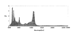
また、上記発明においては、上記太陽電池モジュール用充填材を厚みが600±15μmのシート状としたとき、波長6000nm以上25000nm以下の範囲内におけるピーク面積が12000以下であることが好ましい。
プランクの法則より、太陽熱、もしくはホットスポット現象によりセルが数十℃〜百数十℃の熱を得た場合に、セルが放射すると考えられる熱の波長分布は約6000nm〜25000nmに含まれる。太陽光の輻射熱や太陽電池の発電時に発生する熱等により太陽電池素子の温度が上昇するとその温度特性から発電効率が低下する場合があるが、約6000nm〜25000nmにおけるピーク面積が低ければ吸熱性が低い充填材となり、太陽光の輻射熱や太陽電池の発電時に発生する熱等により太陽電池素子の温度が上昇した場合に、その温度特性から発電効率が低下することを抑制することができる。また、ホットスポット現象などで発生した熱を充填材が蓄えにくくなるので、充填材の白濁を抑制することができ、外観が損なわれることを防ぐことができる。
Moreover, in the said invention, when the said solar cell module filler is made into the sheet form of thickness 600 +/- 15micrometer, it is preferable that the peak area in the wavelength range of 6000 nm or more and 25000 nm or less is 12000 or less.
According to Planck's law, the wavelength distribution of heat that the cell is supposed to emit when the cell obtains heat of several tens of degrees Celsius to several tens of degrees Celsius due to solar heat or hot spot phenomenon is included in about 6000 nm to 25000 nm. When the temperature of the solar cell element rises due to solar radiation heat or heat generated during solar cell power generation, the power generation efficiency may decrease due to its temperature characteristics. However, if the peak area at about 6000 nm to 25000 nm is low, the endothermic property is high. When the temperature of the solar cell element rises due to radiant heat of sunlight, heat generated during power generation of the solar cell, or the like due to a low filler, it is possible to suppress a decrease in power generation efficiency due to its temperature characteristics. Moreover, since it becomes difficult for a filler to store the heat | fever which generate | occur | produced by the hot spot phenomenon etc., the cloudiness of a filler can be suppressed and it can prevent that an external appearance is impaired.
また、本発明においては、上述した太陽電池モジュール用充填材を用いた充填材層を有することを特徴とする太陽電池モジュールを提供する。 Moreover, in this invention, it has a filler layer using the filler for solar cell modules mentioned above, The solar cell module characterized by the above-mentioned is provided.
本発明によれば、上述した太陽電池モジュール用充填材を用いた充填材層を有するので、透明前面基板や太陽電池素子との密着性が良く、外観の美しいものとすることができる。 According to this invention, since it has the filler layer using the filler for solar cell modules mentioned above, it can have good adhesiveness with a transparent front substrate and a solar cell element, and can have a beautiful appearance.
本発明においては、太陽電池モジュール用充填材に含まれる重合用ポリエチレンおよびマスターバッチ用ポリエチレンの密度が比較的低いので、ホットスポット現象などで温度変化があった場合でも、充填材の白濁を抑制することができるという効果を奏する。 In the present invention, since the density of the polyethylene for polymerization and the polyethylene for masterbatch contained in the filler for solar cell modules is relatively low, even when there is a temperature change due to a hot spot phenomenon or the like, the cloudiness of the filler is suppressed. There is an effect that can be.
以下、本発明の太陽電池モジュール用充填材、およびこれを用いた太陽電池モジュール、ならびに太陽電池モジュール用充填材の製造方法について説明する。 Hereinafter, the solar cell module filler of the present invention, a solar cell module using the same, and a method for manufacturing the solar cell module filler will be described.
A.太陽電池モジュール用充填材
まず、本発明の太陽電池モジュール用充填材について説明する。本発明の太陽電池モジュール用充填材は、エチレン性不飽和シラン化合物および重合用ポリエチレンを重合させてなるシラン変性樹脂を含む充填材用樹脂と、紫外線吸収剤、光安定化剤、熱安定化剤およびマスターバッチ用ポリエチレンを含むマスターバッチと、を有する太陽電池モジュール用充填材であって、上記重合用ポリエチレンおよび上記マスターバッチ用ポリエチレンが、0.895〜0.910g/cm3の範囲内の密度を有するメタロセン系直鎖状低密度ポリエチレンであることを特徴とするものである。
A. First, the filler for solar cell modules of this invention is demonstrated. The solar cell module filler of the present invention includes a resin for filler containing a silane-modified resin obtained by polymerizing an ethylenically unsaturated silane compound and a polyethylene for polymerization, an ultraviolet absorber, a light stabilizer, and a heat stabilizer. And a masterbatch containing a masterbatch polyethylene, wherein the polymerization polyethylene and the masterbatch polyethylene have a density in the range of 0.895 to 0.910 g / cm 3. It is a metallocene linear low density polyethylene having
本発明によれば、重合用ポリエチレンおよびマスターバッチ用ポリエチレンの密度が比較的低いので、ホットスポット現象などで発生した熱により温度が上昇し、その後、外気温の降下などで冷却された場合のように温度変化があった場合でも、ポリエチレンの結晶化が妨げられ、充填材の白濁を抑制することができる。その結果、温度が上昇した太陽電池モジュール用充填材が冷却された場合のヘイズ(曇度)の上昇が抑制されるので、温度の変化によるヘイズの変化が少なくなり、外観が損なわれにくい太陽電池モジュール用充填材を得ることができる。 According to the present invention, since the density of the polyethylene for polymerization and the polyethylene for masterbatch is relatively low, the temperature rises due to the heat generated by the hot spot phenomenon and then is cooled by the fall of the outside air temperature. Even when there is a temperature change, the crystallization of polyethylene is hindered, and the cloudiness of the filler can be suppressed. As a result, an increase in haze (cloudiness) when the temperature-increased solar cell module filler is cooled is suppressed, so that the change in the haze due to the temperature change is reduced and the appearance is not easily damaged. A module filler can be obtained.
さらに、本発明においては、重合用ポリエチレンおよびマスターバッチ用ポリエチレンとして、メタロセン系直鎖状低密度ポリエチレンが用いられる。メタロセン系直鎖状低密度ポリエチレンは、シングルサイト触媒であるメタロセン触媒を用いて合成されるものであり、分子量分布が小さいことが知られている。本発明においては、分子量分布が小さく、かつ低密度であるポリエチレンを用いることで、充填材の白濁等を抑制することができる。すなわち、ホットスポット現象などで発生した熱により温度が上昇し、その後、外気温の降下などで冷却された場合に、分子量分布が大きく、密度の高いポリエチレンを用いると、融点が高く結晶化しやすいポリエチレンが先に結晶化し、それが核となることで、充填材の白濁が生じ易くなると考えられるが、メタロセン系直鎖状低密度ポリエチレンのように分子量分布が小さく、かつ低密度であるポリエチレンを用いることによって、充填材の白濁を抑制することができる。 Furthermore, in the present invention, metallocene linear low density polyethylene is used as the polymerization polyethylene and the masterbatch polyethylene. Metallocene-based linear low density polyethylene is synthesized using a metallocene catalyst that is a single site catalyst, and is known to have a small molecular weight distribution. In the present invention, white turbidity of the filler can be suppressed by using polyethylene having a low molecular weight distribution and low density. That is, when the temperature rises due to the heat generated by the hot spot phenomenon and then is cooled by a drop in the outside air temperature, etc., if polyethylene having a large molecular weight distribution and high density is used, the polyethylene has a high melting point and is easily crystallized. It is thought that turbidity of the filler crystallizes first, and the turbidity of the filler is likely to occur. However, polyethylene having a low molecular weight distribution and a low density, such as a metallocene linear low density polyethylene, is used. As a result, the cloudiness of the filler can be suppressed.
また、本発明における充填材用樹脂に含まれるシラン変性樹脂は、上述したように透明前面基板や裏面保護シート、例えばガラス等との密着性に優れ、かつ主鎖がポリエチレンからなるものであることから有害なガスを発生させず、作業環境を悪化させないという利点を有する。 In addition, the silane-modified resin contained in the filler resin in the present invention is excellent in adhesion to a transparent front substrate and a back surface protective sheet such as glass as described above, and the main chain is made of polyethylene. Therefore, there is an advantage that no harmful gas is generated and the working environment is not deteriorated.
さらに、本発明の太陽電池モジュール用充填材は紫外線吸収剤と光安定化剤と熱安定化剤と含有するので、長期にわたり安定した機械強度、接着強度、黄変防止、ひび割れ防止、優れた加工適性を得ることができる。
以下、本発明の太陽電池モジュール用充填材の各構成について説明する。
Furthermore, since the solar cell module filler of the present invention contains an ultraviolet absorber, a light stabilizer, and a heat stabilizer, it has stable mechanical strength, adhesive strength, yellowing prevention, crack prevention, and excellent processing over a long period of time. Aptitude can be obtained.
Hereinafter, each structure of the filler for solar cell modules of this invention is demonstrated.
1.充填材用樹脂
まず、本発明に用いられる充填材用樹脂について説明する。本発明に用いられる充填材用樹脂は、エチレン性不飽和シラン化合物および所定の重合用ポリエチレンを重合させてなるシラン変性樹脂を含むものである。さらに、上記充填材用樹脂は、必要に応じて、添加用ポリエチレンを含有することが好ましい。上記シラン変性樹脂はコストが高いため、添加用ポリエチレンを併用することでコストの低減を図ることができるからである。
以下、充填材用樹脂に含まれるシラン変性樹脂および添加用ポリエチレン、ならびに充填材用樹脂のその他の点について説明する。
1. Filler Resin First, the filler resin used in the present invention will be described. The filler resin used in the present invention contains a silane-modified resin obtained by polymerizing an ethylenically unsaturated silane compound and a predetermined polyethylene for polymerization. Furthermore, it is preferable that the filler resin contains polyethylene for addition as necessary. This is because the cost of the silane-modified resin is high, and the cost can be reduced by using the additive polyethylene together.
Hereinafter, other points of the silane-modified resin and the additive polyethylene contained in the filler resin and the filler resin will be described.
(1)シラン変性樹脂
本発明における充填材用樹脂に含まれるシラン変性樹脂は、エチレン性不飽和シラン化合物および所定の重合用ポリエチレンを重合させてなるものである。このようなシラン変性樹脂は、例えばエチレン性不飽和シラン化合物と重合用ポリエチレンとラジカル発生剤とを混合し、高温で溶融、混練し、エチレン性不飽和シラン化合物を重合用ポリエチレンにグラフト重合させることにより得ることができる。
(1) Silane-modified resin The silane-modified resin contained in the filler resin in the present invention is obtained by polymerizing an ethylenically unsaturated silane compound and a predetermined polymerization polyethylene. Such a silane-modified resin is obtained by, for example, mixing an ethylenically unsaturated silane compound, a polymerization polyethylene and a radical generator, melting and kneading at high temperature, and graft-polymerizing the ethylenically unsaturated silane compound onto the polymerization polyethylene. Can be obtained.
本発明においては、上記重合用ポリエチレンとして、0.895〜0.910g/cm3の範囲内の密度を有するメタロセン系直鎖状低密度ポリエチレンが用いられる。このようなメタロセン系直鎖状低密度ポリエチレンは、密度が比較的低く、分子量分布が小さいことから、温度変化によるポリエチレンの結晶化を妨げ、充填材の白濁を抑制することができる。 In the present invention, a metallocene linear low density polyethylene having a density in the range of 0.895 to 0.910 g / cm 3 is used as the polyethylene for polymerization. Such metallocene-based linear low-density polyethylene has a relatively low density and a small molecular weight distribution. Therefore, crystallization of polyethylene due to temperature change can be prevented, and white turbidity of the filler can be suppressed.
また、上記重合用ポリエチレンは、上述したように0.895〜0.910g/cm3の範囲内の密度を有するものであるが、中でも密度が0.898〜0.905g/cm3の範囲内であることが好ましい。 The above-mentioned polyethylene for polymerization has a density in the range of 0.895 to 0.910 g / cm 3 as described above, and in particular, the density is in the range of 0.898 to 0.905 g / cm 3 . It is preferable that
このような重合用ポリエチレンとしては、メタロセン触媒を用いて合成された直鎖状のポリエチレンであって、上記密度を有するものであれば特に限定されるものではなく、一般的なメタロセン系直鎖状低密度ポリエチレンを用いることができる。また、上記重合用ポリエチレンは1種単独で用いてもよく2種以上を併用してもよい。 The polyethylene for polymerization is not particularly limited as long as it is a linear polyethylene synthesized using a metallocene catalyst and has the above-mentioned density, and is a general metallocene linear Low density polyethylene can be used. Moreover, the said polyethylene for polymerization may be used individually by 1 type, and may use 2 or more types together.
一方、上記シラン変性樹脂に用いられるエチレン性不飽和シラン化合物としては、上記重合用ポリエチレンとグラフト重合するものであれば特に限定されるものではなく、例えばビニルトリメトキシシラン、ビニルトリエトキシシラン、ビニルトリプロポキシシラン、ビニルトリイソプロポキシシラン、ビニルトリブトキシシラン、ビニルトリペンチロキシシラン、ビニルトリフェノキシシラン、ビニルトリベンジルオキシシラン、ビニルトリメチレンジオキシシラン、ビニルトリエチレンジオキシシラン、ビニルプロピオニルオキシシラン、ビニルトリアセトキシシラン、および、ビニルトリカルボキシシランからなる群から選択される少なくとも1種類のものを用いることができる。中でも、ビニルトリメトキシシランが好適に用いられる。 On the other hand, the ethylenically unsaturated silane compound used in the silane-modified resin is not particularly limited as long as it is graft-polymerized with the polymerization polyethylene. For example, vinyltrimethoxysilane, vinyltriethoxysilane, vinyl Tripropoxysilane, vinyltriisopropoxysilane, vinyltributoxysilane, vinyltripentyloxysilane, vinyltriphenoxysilane, vinyltribenzyloxysilane, vinyltrimethylenedioxysilane, vinyltriethylenedioxysilane, vinylpropionyloxysilane , Vinyltriacetoxysilane, and at least one selected from the group consisting of vinyltricarboxysilane can be used. Of these, vinyltrimethoxysilane is preferably used.
本発明の太陽電池モジュール用充填材中のエチレン性不飽和シラン化合物の含有量は、10ppm以上が好ましく、より好ましくは20ppm以上である。本発明においては、上述した重合用ポリエチレンと重合させたエチレン性不飽和シラン化合物を用いることにより、太陽電池モジュール用充填材を用いて太陽電池モジュールとした場合に透明前面基板や裏面シート、例えばガラス等との密着性が実現するものである。上記エチレン性不飽和シラン化合物の含有量が上記範囲に満たない場合は、ガラス等との密着性が不足する。
一方、エチレン性不飽和シラン化合物の含有量は、4000ppm以下が好ましく、より好ましくは3000ppm以下である。上限値は、ガラス等との密着性の観点からは限定されるものではないが、上記範囲を超えるとガラス等との密着性は変わらずコストが高くなる。
The content of the ethylenically unsaturated silane compound in the filler for solar cell module of the present invention is preferably 10 ppm or more, more preferably 20 ppm or more. In the present invention, a transparent front substrate or a back sheet such as glass is obtained by using the ethylenically unsaturated silane compound polymerized with the above-described polymerization polyethylene, when a solar cell module is formed using a filler for a solar cell module. Adhesiveness with etc. is realized. When content of the said ethylenically unsaturated silane compound is less than the said range, adhesiveness with glass etc. is insufficient.
On the other hand, the content of the ethylenically unsaturated silane compound is preferably 4000 ppm or less, more preferably 3000 ppm or less. Although an upper limit is not limited from a viewpoint of adhesiveness with glass etc., if it exceeds the said range, adhesiveness with glass etc. will not change but cost will become high.
上記シラン変性樹脂は、太陽電池モジュール用充填材中に好ましくは1〜80重量%の範囲内、さらに5〜70重量%の範囲内で含有されることが好ましい。本発明の太陽電池モジュール用充填材は、上記シラン変性樹脂を含有することによりガラス等との密着性が高くなる。したがって、ガラス等との密着性、かつコストの点から、上記範囲内が好適である。 The silane-modified resin is preferably contained in the solar cell module filler in the range of 1 to 80% by weight, and more preferably in the range of 5 to 70% by weight. The filler for solar cell modules of this invention becomes high [adhesiveness with glass etc.] by containing the said silane modified resin. Therefore, the above range is preferable from the viewpoints of adhesion to glass and the like and cost.
また、上記シラン変性樹脂は、190℃でのメルトマスフローレートが0.5〜10g/10分であるものが好ましく、1〜8g/10分であるものがより好ましい。本発明の太陽電池モジュール用充填材の成形性、および透明前面基板や裏面保護シートとの接着性等に優れるからである。
さらに、上記シラン変性樹脂の融点は、110℃以下であることが好ましい。本発明の太陽電池モジュール用充填材を用いた太陽電池モジュールの製造時において、加工性等の面から上記範囲が好適である。なお、上記融点は、プラスチックの転移温度測定方法(JIS K 7121)に準拠し、示差走査熱量分析(DSC)により測定した値とする。この際、融点ピークが2つ以上存在する場合は高い温度の方を融点とする。
The silane-modified resin preferably has a melt mass flow rate at 190 ° C. of 0.5 to 10 g / 10 minutes, more preferably 1 to 8 g / 10 minutes. It is because it is excellent in the moldability of the solar cell module filler of the present invention and the adhesiveness to the transparent front substrate and the back surface protective sheet.
Furthermore, the melting point of the silane-modified resin is preferably 110 ° C. or lower. When manufacturing a solar cell module using the solar cell module filler of the present invention, the above range is preferable in terms of workability and the like. The melting point is a value measured by differential scanning calorimetry (DSC) in accordance with a plastic transition temperature measurement method (JIS K 7121). At this time, when two or more melting points exist, the higher temperature is defined as the melting point.
上記シラン変性樹脂に添加するラジカル発生剤としては、例えばジイソプロピルベンゼンヒドロパーオキサイド、2,5−ジメチル−2,5−ジ(ヒドロパーオキシ)ヘキサン等のヒドロパーオキサイド類;ジ−t−ブチルパーオキサイド、t−ブチルクミルパーオキサイド、ジクミルパーオキサイド、2,5−ジメチル−2,5−ジ(t−ブチルパーオキシ)ヘキサン、2,5−ジメチル−2,5−ジ(t−パーオキシ)ヘキシン−3等のジアルキルパーオキサイド類;ビス−3,5,5−トリメチルヘキサノイルパーオキサイド、オクタノイルパーオキサイド、ベンゾイルパーオキサイド、o−メチルベンゾイルパーオキサイド、2,4−ジクロロベンゾイルパーオキサイド等のジアシルパーオキサイド類;t−ブチルパーオキシアセテート、t−ブチルパーオキシ−2−エチルヘキサノエート、t−ブチルパーオキシピバレート、t−ブチルパーオキシオクトエート、t−ブチルパーオキシイソプロピルカーボネート、t−ブチルパーオキシベンゾエート、ジ−t−ブチルパーオキシフタレート、2,5−ジメチル−2,5−ジ(ベンゾイルパーオキシ)ヘキサン、2,5−ジメチル−2,5−ジ(ベンゾイルパーオキシ)ヘキシン−3等のパーオキシエステル類;メチルエチルケトンパーオキサイド、シクロヘキサノンパーオキサイド等のケトンパーオキサイド類等の有機過酸化物、または、アゾビスイソブチロニトリル、アゾビス(2,4−ジメチルバレロニトリル)等のアゾ化合物等が挙げられる。 Examples of the radical generator added to the silane-modified resin include hydroperoxides such as diisopropylbenzene hydroperoxide and 2,5-dimethyl-2,5-di (hydroperoxy) hexane; Oxide, t-butylcumyl peroxide, dicumyl peroxide, 2,5-dimethyl-2,5-di (t-butylperoxy) hexane, 2,5-dimethyl-2,5-di (t-peroxy) Dialkyl peroxides such as hexyne-3; bis-3,5,5-trimethylhexanoyl peroxide, octanoyl peroxide, benzoyl peroxide, o-methylbenzoyl peroxide, 2,4-dichlorobenzoyl peroxide, etc. Diacyl peroxides; t-butyl peroxyacete T-butyl peroxy-2-ethylhexanoate, t-butyl peroxypivalate, t-butyl peroxy octoate, t-butyl peroxyisopropyl carbonate, t-butyl peroxybenzoate, di-t- Peroxyesters such as butyl peroxyphthalate, 2,5-dimethyl-2,5-di (benzoylperoxy) hexane, 2,5-dimethyl-2,5-di (benzoylperoxy) hexyne-3; methyl ethyl ketone Examples thereof include organic peroxides such as ketone peroxides such as peroxide and cyclohexanone peroxide, or azo compounds such as azobisisobutyronitrile and azobis (2,4-dimethylvaleronitrile).
上記ラジカル発生剤は、上記シラン変性樹脂中に0.001重量%以上含まれることが好ましい。上記範囲未満では、エチレン性不飽和シラン化合物と重合用ポリエチレンとのラジカル重合が起こりにくいからである。 The radical generator is preferably contained in the silane-modified resin in an amount of 0.001% by weight or more. This is because radical polymerization between the ethylenically unsaturated silane compound and the polymerization polyethylene hardly occurs when the amount is less than the above range.
なお、本発明に用いられるシラン変性樹脂は、合わせガラス用途にも使用できるものである。合わせガラスは、ガラスとガラスとの間に柔軟で強靭な樹脂等をはさんで加熱圧着して作製されるものであるので、ガラスとの密着性の点から、上記シラン変性樹脂を用いることができる。 In addition, the silane modified resin used for this invention can be used also for a laminated glass use. Laminated glass is produced by thermocompression bonding between a glass and a glass with a flexible and tough resin or the like. From the viewpoint of adhesion to glass, the above silane-modified resin may be used. it can.
また、上記シラン変性樹脂の調製方法としては、特に限定されるものではないが、例えばエチレン性不飽和シラン化合物と重合用ポリエチレンとラジカル発生剤との混合物を、加熱溶融混合し、エチレン性不飽和シラン化合物を重合用ポリエチレンにグラフト重合させる方法を挙げることができる。この際、加熱温度は300℃以下が好ましく、さらには270℃以下が好ましく、最も好ましい温度は230℃以下である。 Further, the method for preparing the silane-modified resin is not particularly limited. For example, a mixture of an ethylenically unsaturated silane compound, a polyethylene for polymerization, and a radical generator is heated and melted and mixed to obtain an ethylenically unsaturated group. A method of graft polymerization of a silane compound onto polyethylene for polymerization can be mentioned. At this time, the heating temperature is preferably 300 ° C. or lower, more preferably 270 ° C. or lower, and the most preferable temperature is 230 ° C. or lower.
(2)添加用ポリエチレン
次に、本発明に用いられる添加用ポリエチレンについて説明する。上述したように、上記充填材用樹脂は、必要に応じて、添加用ポリエチレンを含有することが好ましい。上記添加用ポリエチレンとしては、具体的には、上記シラン変性樹脂に用いられる重合用ポリエチレンと同様のもの、すなわち、0.895〜0.910g/cm3の範囲内の密度を有するメタロセン系直鎖状低密度ポリエチレンを挙げることができる。本発明においては、特に、添加用ポリエチレンが上記重合用ポリエチレンと同一のポリエチレンであることが好ましい。
(2) Additive polyethylene Next, the additive polyethylene used in the present invention will be described. As described above, it is preferable that the filler resin contains polyethylene for addition as necessary. Specifically, the additive polyethylene is the same as the polymerization polyethylene used in the silane-modified resin, that is, a metallocene linear chain having a density in the range of 0.895 to 0.910 g / cm 3. Can be mentioned low density polyethylene. In the present invention, it is particularly preferable that the additive polyethylene is the same polyethylene as the above-described polymerization polyethylene.
添加用ポリエチレンの含有量は、上記シラン変性樹脂100重量部に対し、0.01重量部〜9900重量部が好ましく、90重量部〜9,900重量部がより好ましい。また、上記シラン変性樹脂を2種以上用いる場合には、その合計量100重量部に対し、添加用ポリエチレンの含有量が上記範囲となることが好ましい。 The content of polyethylene for addition is preferably 0.01 to 9900 parts by weight and more preferably 90 to 9,900 parts by weight with respect to 100 parts by weight of the silane-modified resin. Moreover, when using 2 or more types of the said silane modified resin, it is preferable that content of the polyethylene for addition becomes the said range with respect to the total amount of 100 weight part.
また、上記添加用ポリエチレンは、190℃でのメルトマスフローレートが0.5〜10g/10分であるものが好ましく、1〜8g/10分であるものがより好ましい。本発明の太陽電池モジュール用充填材の成形性等に優れるからである。
さらに、上記添加用ポリエチレンの融点は、130℃以下であることが好ましい。本発明の太陽電池モジュール用充填材を用いた太陽電池モジュールの製造時における加工性等の面から上記範囲が好適である。なお、上記融点は、上述した方法により測定した値とする。
The polyethylene for addition preferably has a melt mass flow rate at 190 ° C. of 0.5 to 10 g / 10 min, more preferably 1 to 8 g / 10 min. It is because it is excellent in the moldability etc. of the filler for solar cell modules of this invention.
Furthermore, the melting point of the additive polyethylene is preferably 130 ° C. or lower. The above range is preferable from the viewpoint of workability and the like during the production of the solar cell module using the solar cell module filler of the present invention. The melting point is a value measured by the method described above.
(3)その他
本発明に用いられる充填材用樹脂は、190℃でのメルトマスフローレートが0.5〜10g/10分であるものが好ましく、1〜8g/10分であるものがより好ましい。太陽電池モジュール用充填材の成形性、透明前面基板および裏面保護シートとの接着性等に優れるからである。
また、充填材用樹脂の融点は130℃以下であることが好ましい。本発明の太陽電池モジュール用充填材を用いた太陽電池モジュールの製造時において、加工性等の面から上記範囲が好適である。また、太陽電池モジュールの構成部材、例えば太陽電池素子や透明前面基板を再利用する場合に、融点がこの程度であれば容易に再利用することができるからである。なお、上記融点は、上述した方法により測定した値とする。
(3) Others The resin for filler used in the present invention preferably has a melt mass flow rate at 190 ° C. of 0.5 to 10 g / 10 minutes, more preferably 1 to 8 g / 10 minutes. It is because it is excellent in the moldability of the filler for solar cell modules, adhesiveness with a transparent front substrate and a back surface protection sheet.
Moreover, it is preferable that melting | fusing point of resin for fillers is 130 degrees C or less. When manufacturing a solar cell module using the filler for solar cell module of the present invention, the above range is preferable from the viewpoint of workability and the like. In addition, when the constituent members of the solar cell module, for example, the solar cell elements and the transparent front substrate are reused, if the melting point is about this level, they can be easily reused. The melting point is a value measured by the method described above.
2.マスターバッチ
次に、本発明に用いられるマスターバッチについて説明する。本発明に用いられるマスターバッチは、紫外線吸収剤、光安定化剤、熱安定化剤およびマスターバッチ用ポリエチレンを含むものである。
以下、マスターバッチに含まれるマスターバッチ用ポリエチレン、紫外線吸収剤、光安定化剤および熱安定化剤について説明する。
2. Next, the master batch used in the present invention will be described. The masterbatch used in the present invention contains an ultraviolet absorber, a light stabilizer, a heat stabilizer and a masterbatch polyethylene.
Hereinafter, the masterbatch polyethylene, the ultraviolet absorber, the light stabilizer and the heat stabilizer contained in the masterbatch will be described.
(1)マスターバッチ用ポリエチレン
まず、本発明に用いられるマスターバッチ用ポリエチレンについて説明する。本発明においては、マスターバッチ用ポリエチレンとして、0.895〜0.910g/cm3の範囲内の密度を有するメタロセン系直鎖状低密度ポリエチレンが用いられる。このようなメタロセン系直鎖状低密度ポリエチレンは、密度が比較的低く、分子量分布が小さいことから、温度変化によるポリエチレンの結晶化を妨げ、充填材の白濁を抑制することができる。
(1) Masterbatch polyethylene First, the masterbatch polyethylene used in the present invention will be described. In the present invention, a metallocene linear low density polyethylene having a density in the range of 0.895 to 0.910 g / cm 3 is used as the polyethylene for the masterbatch. Such metallocene-based linear low-density polyethylene has a relatively low density and a small molecular weight distribution. Therefore, crystallization of polyethylene due to temperature change can be prevented, and white turbidity of the filler can be suppressed.
上記マスターバッチ用ポリエチレンとしては、上記「1.充填材用樹脂」に記載した重合用ポリエチレンと同様のものを用いることができるので、ここでの説明は省略する。 As the masterbatch polyethylene, the same polymer as the polymerization polyethylene described in the above "1. Filler resin" can be used, and the description thereof is omitted here.
(2)紫外線吸収剤
次に、本発明に用いられる紫外線吸収剤について説明する。本発明に用いられる紫外線吸収剤は、太陽光中の有害な紫外線を吸収して、分子内で無害な熱エネルギーへと変換し、太陽電池モジュール用充填材中の光劣化開始の活性種が励起されるのを防止するものである。具体的には、ベンゾフェノン系、ベンゾトリアゾール系、サルチレート系、アクリルニトリル系、金属錯塩系、ヒンダードアミン系、あるいは、超微粒子酸化チタン(粒子径:0.01μm〜0.06μm)および超微粒子酸化亜鉛(粒子径:0.01μm〜0.04μm)等の無機系などの紫外線吸収剤が挙げられる。
(2) Ultraviolet absorber Next, the ultraviolet absorber used for this invention is demonstrated. The ultraviolet absorber used in the present invention absorbs harmful ultraviolet rays in sunlight, converts them into innocuous heat energy in the molecule, and excites active species that initiate photodegradation in the solar cell module filler. It is intended to prevent this. Specifically, benzophenone-based, benzotriazole-based, salicylate-based, acrylonitrile-based, metal complex-based, hindered amine-based, or ultrafine titanium oxide (particle diameter: 0.01 μm to 0.06 μm) and ultrafine zinc oxide ( Inorganic ultraviolet absorbers such as particle diameter: 0.01 μm to 0.04 μm) can be used.
太陽電池モジュール用充填材中の紫外線吸収剤の含有量としては、その粒子形状、密度等によって異なるが、具体的には0.075重量%〜0.3重量%の範囲内であることが好ましく、より好ましくは0.1重量%〜0.2重量%の範囲内である。なお、マスターバッチ中の紫外線吸収剤の含有量としては、特に限定されるものではないが、太陽電池モジュール用充填材中の紫外線吸収剤の含有量が上記の範囲となるように、マスターバッチ中の紫外線吸収剤の含有量を選択することが好ましい。 The content of the ultraviolet absorber in the solar cell module filler varies depending on the particle shape, density, etc., but is preferably in the range of 0.075 wt% to 0.3 wt%. More preferably, it is in the range of 0.1% by weight to 0.2% by weight. The content of the ultraviolet absorber in the masterbatch is not particularly limited, but the masterbatch is used so that the content of the ultraviolet absorber in the solar cell module filler is within the above range. It is preferable to select the content of the ultraviolet absorber.
(3)光安定化剤
次に、本発明に用いられる光安定化剤について説明する。本発明に用いられる光安定化剤は、太陽電池モジュール用充填材中の光劣化開始の活性種を捕捉し、光酸化を防止するものである。具体的には、ヒンダードアミン系化合物、ヒンダードピペリジン系化合物などの光安定化剤が挙げられる。
(3) Light Stabilizer Next, the light stabilizer used in the present invention will be described. The light stabilizer used in the present invention captures active species at the start of photodegradation in the solar cell module filler and prevents photooxidation. Specific examples include light stabilizers such as hindered amine compounds and hindered piperidine compounds.
太陽電池モジュール用充填材中の光安定化剤の含有量としては、その粒子形状、密度等によって異なるが、具体的には0.1重量%〜0.4重量%の範囲内であることが好ましく、より好ましくは0.15重量%〜0.3重量%の範囲内である。なお、マスターバッチ中の光安定化剤の含有量としては、特に限定されるものではないが、太陽電池モジュール用充填材中の光安定化剤の含有量が上記の範囲となるように、マスターバッチ中の光安定化剤の含有量を選択することが好ましい。 The content of the light stabilizer in the solar cell module filler varies depending on the particle shape, density, and the like, but is specifically in the range of 0.1 wt% to 0.4 wt%. More preferably, it is in the range of 0.15 wt% to 0.3 wt%. The content of the light stabilizer in the masterbatch is not particularly limited, but the master is adjusted so that the content of the light stabilizer in the solar cell module filler is within the above range. It is preferred to select the content of light stabilizer in the batch.
(4)熱安定化剤
次に、本発明に用いられる熱安定化剤について説明する。本発明に用いられる熱安定化剤は、太陽電池モジュール用充填材の酸化劣化を防止するものである。具体的には、トリス(2,4−ジ−tert−ブチルフェニル)フォスファイト、ビス[2,4−ビス(1,1−ジメチルエチル)−6−メチルフェニル]エチルエステル亜リン酸、テトラキス(2,4−ジ−tert−ブチルフェニル)[1,1−ビフェニル]−4,4´−ジイルビスホスフォナイト、および、ビス(2,4−ジ−tert−ブチルフェニル)ペンタエリスリトールジフォスファイト等のリン系熱安定化剤;8−ヒドロキシ−5,7−ジ−tert−ブチル−フラン−2−オンとo−キシレンとの反応生成物等のラクトン系熱安定化剤;フェノール系熱安定化剤;アミン系熱安定化剤;硫黄系熱安定化剤;などを挙げることができる。また、これらを1種または2種以上を用いることもできる。中でも、リン系熱安定化剤およびラクトン系熱安定化剤を併用して用いることが好ましい。
(4) Thermal Stabilizer Next, the thermal stabilizer used in the present invention will be described. The heat stabilizer used in the present invention prevents oxidative deterioration of the solar cell module filler. Specifically, tris (2,4-di-tert-butylphenyl) phosphite, bis [2,4-bis (1,1-dimethylethyl) -6-methylphenyl] ethyl ester phosphorous acid, tetrakis ( 2,4-di-tert-butylphenyl) [1,1-biphenyl] -4,4′-diylbisphosphonite and bis (2,4-di-tert-butylphenyl) pentaerythritol diphosphite Phosphorus heat stabilizers such as: Lactone heat stabilizers such as reaction products of 8-hydroxy-5,7-di-tert-butyl-furan-2-one and o-xylene; Phenol heat stabilizers An amine heat stabilizer; a sulfur heat stabilizer; Moreover, these can also use 1 type (s) or 2 or more types. Among these, it is preferable to use a phosphorus heat stabilizer and a lactone heat stabilizer in combination.
太陽電池モジュール用充填材中の熱安定化剤の含有量としては、その粒子形状、密度等によって異なるが、具体的には0.01重量%〜0.16重量%の範囲内であることが好ましく、より好ましくは0.01重量%〜0.17重量%の範囲内である。なお、マスターバッチ中の熱安定化剤の含有量としては、特に限定されるものではないが、太陽電池モジュール用充填材中の熱安定化剤の含有量が上記の範囲となるように、マスターバッチ中の熱安定化剤の含有量を選択することが好ましい。 The content of the heat stabilizer in the solar cell module filler varies depending on the particle shape, density, and the like, but is specifically in the range of 0.01 wt% to 0.16 wt%. Preferably, it is in the range of 0.01% by weight to 0.17% by weight. The content of the heat stabilizer in the master batch is not particularly limited, but the master is adjusted so that the content of the heat stabilizer in the solar cell module filler is within the above range. It is preferred to select the content of heat stabilizer in the batch.
なお、上記熱安定化剤の含有量の測定方法としては、還流・再沈殿法による前処理を行い、定性分析および定量分析を行う方法を用いるものとする。すなわち、(1)太陽電池モジュール用充填材に溶媒を加えて還流抽出を行い、樹脂成分および添加剤成分を溶解させる。(2)この溶解液に貧溶媒を加えて樹脂成分を沈殿させた後、ろ過を行う。(3)ろ液を濃縮、定容したものを供試液とする。(4)得られた供試液について、定性分析および定量分析を行う。この際、定性分析には、ガスクロマトグラフ/質量分析装置(GC/MS)、および高速液体クロマトグラフ/紫外線検出器(HPLC/UVD)を用い、定量分析には、ガスクロマトグラフ/水素炎イオン化検出器(GC/FID)を用いるものとする。 In addition, as a measuring method of content of the said heat stabilizer, the method of performing the pre-processing by a recirculation | refluxing / reprecipitation method and performing a qualitative analysis and a quantitative analysis shall be used. That is, (1) A solvent is added to the solar cell module filler and reflux extraction is performed to dissolve the resin component and the additive component. (2) A poor solvent is added to the solution to precipitate the resin component, followed by filtration. (3) Concentrate the filtrate and make a constant volume as the test solution. (4) Qualitative analysis and quantitative analysis are performed on the obtained test solution. At this time, a gas chromatograph / mass spectrometer (GC / MS) and a high performance liquid chromatograph / ultraviolet detector (HPLC / UVD) are used for qualitative analysis, and a gas chromatograph / hydrogen flame ionization detector is used for quantitative analysis. (GC / FID) is used.
3.太陽電池モジュール用充填材
本発明においては、太陽電池モジュール用充填材の密度が0.895g/cm3〜0.910g/cm3程度であることが好ましく、より好ましくは0.898g/cm3〜0.905g/cm3程度である。上述したように、本発明においては、重合用ポリエチレンおよびマスターバッチ用ポリエチレンの密度が所定の範囲であることから、太陽電池モジュール用充填材全体の密度としては上記範囲内であることが好ましいのである。
3. In the filler present invention for a solar cell module, it is preferable that the density of the encapsulant for a photovoltaic module is 0.895g / cm 3 ~0.910g / cm 3, more preferably about 0.898 g / cm 3 ~ It is about 0.905 g / cm 3 . As described above, in the present invention, since the density of the polymerization polyethylene and the masterbatch polyethylene is within a predetermined range, the density of the entire solar cell module filler is preferably within the above range. .
なお、上記密度は、JIS K 7112に規定の密度勾配管法により測定した値とする。具体的には、比重の異なる液体を入れた試験管の中へサンプルを投入し、止まった位置を読み取ることにより密度を測定した。 In addition, the said density shall be the value measured by the density gradient tube method prescribed | regulated to JISK7112. Specifically, the sample was put into a test tube containing liquids having different specific gravities, and the density was measured by reading the stopped position.
本発明においては、太陽電池モジュール用充填材を厚みが600±15μmのシート状としたとき、波長6000nm以上25000nm以下の範囲内におけるピーク面積が12000以下、中でも10700以下であることが好ましい。
なお、上記ピーク面積は、FT−IR610(日本分光株式会社製)を用いて、赤外分光法により6000nmから25000nmの赤外吸収スペクトルを測定し、得られた赤外吸収スペクトルから、ピーク面積が算出される。なお、本発明においては、上記ピーク面積を市販のソフトウェア(Spectra Manager for Windows(登録商標)95/NTスペクトル解析version1.50.00[Build8] 日本分光株式会社製)を用いて算出した。
In the present invention, when the solar cell module filler is in the form of a sheet having a thickness of 600 ± 15 μm, the peak area within the wavelength range of 6000 nm to 25000 nm is preferably 12000 or less, particularly preferably 10700 or less.
In addition, the said peak area measured the infrared absorption spectrum of 6000 nm to 25000 nm by an infrared spectroscopy using FT-IR610 (made by JASCO Corporation), and a peak area was obtained from the obtained infrared absorption spectrum. Calculated. In the present invention, the peak area was calculated using commercially available software (Spectra Manager for Windows (registered trademark) 95 / NT spectrum analysis version 1.50.00 [Build8] manufactured by JASCO Corporation).
さらに、太陽電池モジュール用充填材は、光線透過性が高いことが好ましい。具体的には、太陽電池モジュール用充填材の全光線透過率が、70%〜100%の範囲内であることが好ましく、より好ましくは80%〜100%の範囲内、最も好ましくは90%〜100%の範囲内である。なお、上記全光線透過率は、通常の方法により測定することができ、例えばカラーコンピュータにより測定することができる。 Furthermore, it is preferable that the filler for solar cell modules has high light transmittance. Specifically, the total light transmittance of the filler for solar cell modules is preferably in the range of 70% to 100%, more preferably in the range of 80% to 100%, and most preferably 90% to It is in the range of 100%. In addition, the said total light transmittance can be measured by a normal method, for example, can be measured with a color computer.
また、太陽電池モジュール用充填材がシート状に成形されたものである場合、その厚みは、50〜2000μmの範囲内であることが好ましく、特に100〜1250μmの範囲内であることが好ましい。上記範囲より薄い場合はセルを支持することができずセルの破損が生じやすくなり、上記範囲より厚い場合はモジュール重量が重くなり設置時などの作業性が悪いばかりでなく、コスト面でも不利となる場合もあるからである。
なお、本発明の太陽電池モジュール用充填材の製造方法については、後述する「C.太陽電池モジュール用充填材の製造方法」の欄に記載するので、ここでの説明は省略する。
Moreover, when the solar cell module filler is formed into a sheet shape, the thickness thereof is preferably in the range of 50 to 2000 μm, and particularly preferably in the range of 100 to 1250 μm. If it is thinner than the above range, the cell cannot be supported and the cell is likely to be damaged.If it is thicker than the above range, the module becomes heavy and not only the workability such as installation is bad, but also in terms of cost. It is because it may become.
In addition, since it describes in the column of the "C. manufacturing method of the filler for solar cell modules" mentioned later about the manufacturing method of the filler for solar cell modules of this invention, description here is abbreviate | omitted.
B.太陽電池モジュール
次に、本発明の太陽電池モジュールについて説明する。本発明の太陽電池モジュールは、上述した太陽電池モジュール用充填材を用いた充填材層を有することを特徴とするものである。
B. Next, the solar cell module of the present invention will be described. The solar cell module of the present invention has a filler layer using the above-described filler for solar cell module.
図1は、本発明の太陽電池モジュールの一例を示す概略断面図である。図1に例示するように、複数個の太陽電池素子1が同一平面状に並べられており、太陽電池素子1間には配線電極2および取り出し電極3が配置されている。太陽電池素子1は、その両面が表側充填材層4aと裏側充填材層4bにより挟持されており、表側充填材層4aの外側には透明前面基板5が積層され、裏側充填材層4bの外側には裏面保護シート6が積層されている。この太陽電池モジュールTはアルミニウムなどの外枠7で固定されていてもよい。本発明においては、表側充填材層4aおよび裏面充填材層4bの少なくとも一方に、上述した太陽電池モジュール用充填材を用いることができ、中でも表面充填材層4aに用いることが好ましい。
FIG. 1 is a schematic cross-sectional view showing an example of the solar cell module of the present invention. As illustrated in FIG. 1, a plurality of solar cell elements 1 are arranged in the same plane, and a
本発明によれば、上述した太陽電池モジュール用充填材を用いた充填材層を有するので、上述した利点を有する太陽電池モジュールとすることができる。具体的には、ホットスポット現象等による温度変化の影響による充填材の白濁を抑制することができ、外観が損なわれるのを防ぐことができる。
以下、本発明の太陽電池モジュールの構成について説明する。
According to this invention, since it has the filler layer using the filler for solar cell modules mentioned above, it can be set as the solar cell module which has the advantage mentioned above. Specifically, it is possible to suppress the white turbidity of the filler due to the influence of a temperature change due to a hot spot phenomenon or the like, and to prevent the appearance from being damaged.
Hereinafter, the configuration of the solar cell module of the present invention will be described.
1.充填材層
本発明に用いられる充填材層は、「A.太陽電池用モジュール用充填材」に記載の充填材を用いてなるものである。上記充填材層は、太陽電池素子と透明前面基板または裏面保護シートとを接着させる役割をもつものであるため、透明前面基板または裏面保護シートとの密着性が高いことが好ましい。具体的には、充填材層の25℃雰囲気下における180°剥離試験において測定された透明前面基板または裏面保護シートとの剥離強度が、1N/15mm幅〜150N/15mm幅の範囲内であることが好ましく、より好ましくは3N/15mm幅〜150N/15mm幅、最も好ましくは10N/15mm幅〜150N/15mm幅の範囲内である。
1. Filler Layer The filler layer used in the present invention is formed using the filler described in “A. Filler for Solar Cell Module”. Since the said filler layer has a role which adhere | attaches a solar cell element, a transparent front substrate, or a back surface protection sheet, it is preferable that adhesiveness with a transparent front substrate or a back surface protection sheet is high. Specifically, the peel strength with the transparent front substrate or the back surface protective sheet measured in the 180 ° peel test in a 25 ° C. atmosphere of the filler layer is in the range of 1 N / 15 mm width to 150 N / 15 mm width. More preferably, it is in the range of 3 N / 15 mm width to 150 N / 15 mm width, and most preferably in the range of 10 N / 15 mm width to 150 N / 15 mm width.
なお、上記剥離強度は以下の試験方法により得た値とする。
試験機:エー・アンド・ディー(A&D)株式会社製の引っ張り試験機〔機種名:テンシロン〕
測定角度:180°剥離
剥離速度:50mm/min
The peel strength is a value obtained by the following test method.
Testing machine: Tensile testing machine (model name: Tensilon) manufactured by A & D Co., Ltd.
Measurement angle: 180 ° Peeling peeling speed: 50 mm / min
また、充填材層は、密着性を長期間保持していることが好ましく、太陽電池モジュールを温度85℃、湿度85%の高温多湿状態にて1000時間放置した後の25℃雰囲気下における180°剥離試験において測定された透明前面基板または裏面保護シートとの剥離強度が、0.5N/15mm幅〜140N/15mm幅の範囲内であることが好ましく、より好ましくは3N/15mm幅〜140N/15mm幅、さらに好ましくは10N/15mm幅〜140N/15mm幅の範囲内である。なお、測定方法は上述した方法と同様の方法が用いられる。 Moreover, it is preferable that the filler layer keeps the adhesion for a long period of time, and the solar cell module is left at a temperature of 85 ° C. and a humidity of 85% for 1000 hours in a high-temperature and high-humidity state for 180 hours in a 25 ° C. atmosphere. The peel strength with the transparent front substrate or back protective sheet measured in the peel test is preferably in the range of 0.5 N / 15 mm width to 140 N / 15 mm width, more preferably 3 N / 15 mm width to 140 N / 15 mm. The width is more preferably within the range of 10 N / 15 mm width to 140 N / 15 mm width. The measuring method is the same method as described above.
充填材層の厚みは、50〜2000μmの範囲内であることが好ましく、特に100〜1250μmの範囲内であることが好ましい。上記範囲より薄い場合はセルを支持することができずセルの破損が生じやすくなり、上記範囲より厚い場合はモジュール重量が重くなり設置時などの作業性が悪いばかりでなく、コスト面でも不利となる場合もあるからである。 The thickness of the filler layer is preferably in the range of 50 to 2000 μm, particularly preferably in the range of 100 to 1250 μm. If it is thinner than the above range, the cell cannot be supported and the cell is likely to be damaged.If it is thicker than the above range, the module becomes heavy and not only the workability such as installation is bad, but also in terms of cost. It is because it may become.
2.太陽電池素子
本発明に用いられる太陽電池素子としては、光起電力としての機能を有するものであれば特に限定されるものではなく、一般に太陽電池素子として使用されているものを使用することができる。例えば、単結晶シリコン型太陽電池素子、多結晶シリコン型太陽電池素子等の結晶シリコン太陽電池素子、シングル結合型もしくはタンデム構造型等からなるアモルファスシリコン太陽電池素子、ガリウムヒ素(GaAs)やインジウムリン(InP)等のIII−V族化合物半導体太陽電池素子、カドミウムテルル(CdTe)や銅インジウムセレナイド(CuInSe2)等のII−VI族化合物半導体太陽電池素子などが挙げられる。また、薄膜多結晶性シリコン太陽電池素子、薄膜微結晶性シリコン太陽電池素子、薄膜結晶シリコン太陽電池素子とアモルファスシリコン太陽電池素子とのハイブリッド素子等も使用することができる。
2. Solar cell element The solar cell element used in the present invention is not particularly limited as long as it has a function as a photovoltaic power, and those generally used as solar cell elements can be used. . For example, a crystalline silicon solar cell element such as a single crystal silicon type solar cell element or a polycrystalline silicon type solar cell element, an amorphous silicon solar cell element made of a single bond type or a tandem structure type, gallium arsenide (GaAs) or indium phosphide ( Examples include III-V group compound semiconductor solar cell elements such as InP) and II-VI group compound semiconductor solar cell elements such as cadmium tellurium (CdTe) and copper indium selenide (CuInSe 2 ). A thin film polycrystalline silicon solar cell element, a thin film microcrystalline silicon solar cell element, a hybrid element of a thin film crystalline silicon solar cell element and an amorphous silicon solar cell element, or the like can also be used.
これらの太陽電池素子は、例えば、ガラス基板、プラスチック基板、金属基板等の基板上に、pn接合構造等の結晶シリコン、p−i−n接合構造等のアモルファスシリコン、化合物半導体等の起電力部分が形成されて構成される。 These solar cell elements are formed on a substrate such as a glass substrate, a plastic substrate, or a metal substrate, for example, a crystalline silicon such as a pn junction structure, an amorphous silicon such as a pin junction structure, or an electromotive force portion such as a compound semiconductor. Is formed and configured.
本発明の太陽電池モジュールにおいては、図1に示すように、太陽電池素子1が複数個並べられている。この太陽電池素子1が太陽光に照らされると、電子(−)と正孔(+)が発生し、太陽電池素子間に配置された配線電極2および取り出し電極3により電流が流れ出す仕組みである。
In the solar cell module of the present invention, a plurality of solar cell elements 1 are arranged as shown in FIG. When the solar cell element 1 is illuminated with sunlight, electrons (−) and holes (+) are generated, and a current flows out by the
3.透明前面基板
本発明において、透明前面基板は、モジュール内部を風雨や外部衝撃、火災などから保護し、太陽電池モジュールの屋外暴露における長期信頼性を確保する機能を有する。
このような透明前面基板としては、太陽光の透過性、電気絶縁性を有し、かつ、機械的もしくは化学的ないし物理的強度に優れているものであれば特に限定されるものではなく、一般に太陽電池モジュール用の透明前面基板として用いられているものを使用することができる。例えば、ガラス板、フッ素系樹脂シート、環状ポリオレフィン系樹脂シート、ポリカーボネート系樹脂シート、ポリ(メタ)アクリル系樹脂シート、ポリアミド系樹脂シート、またはポリエステル系樹脂シートなどが挙げられる。これらの中でも、本発明における透明前面基板としては、ガラス板を用いるのが好ましい。ガラス板は、耐熱性に優れており、使用済みの太陽電池モジュールから各構成部材を分離し、ガラス板表面に付着した表側充填材を除去する際の加熱温度を十分に高く設定することができるため、リユースもしくはリサイクルが容易なものとなるからである。
3. Transparent Front Substrate In the present invention, the transparent front substrate has a function of protecting the inside of the module from wind and rain, external impact, fire, and the like, and ensuring long-term reliability in outdoor exposure of the solar cell module.
Such a transparent front substrate is not particularly limited as long as it has sunlight permeability, electrical insulation, and is excellent in mechanical or chemical or physical strength. What is used as a transparent front substrate for solar cell modules can be used. Examples thereof include a glass plate, a fluorine resin sheet, a cyclic polyolefin resin sheet, a polycarbonate resin sheet, a poly (meth) acrylic resin sheet, a polyamide resin sheet, and a polyester resin sheet. Among these, it is preferable to use a glass plate as the transparent front substrate in the present invention. The glass plate is excellent in heat resistance, and can be set to a sufficiently high heating temperature when separating each constituent member from the used solar cell module and removing the front-side filler adhering to the glass plate surface. Therefore, reuse or recycling is easy.
4.裏面保護シート
裏面保護シートは、太陽電池モジュール裏面を外界から保護する耐候性フィルムである。本発明に用いられる裏面保護シートとしては、例えばアルミニウム等の金属板もしくは金属箔、フッ素系樹脂シート、環状ポリオレフィン系樹脂シート、ポリカーボネート系樹脂シート、ポリ(メタ)アクリル系樹脂シート、ポリアミド系樹脂シート、ポリエステル系樹脂シート、または耐候性フィルムとバリアフィルムとをラミネート積層した複合シートなどが挙げられる。
本発明に用いられる裏面保護シートの厚みは、20μm〜500μmの範囲内が好ましく、より好ましくは60μm〜350μmの範囲内である。
4). Back surface protection sheet The back surface protection sheet is a weather-resistant film that protects the back surface of the solar cell module from the outside. Examples of the back surface protective sheet used in the present invention include a metal plate or metal foil such as aluminum, a fluorine resin sheet, a cyclic polyolefin resin sheet, a polycarbonate resin sheet, a poly (meth) acrylic resin sheet, and a polyamide resin sheet. , A polyester resin sheet, or a composite sheet obtained by laminating and laminating a weather resistant film and a barrier film.
The thickness of the back surface protective sheet used in the present invention is preferably in the range of 20 μm to 500 μm, more preferably in the range of 60 μm to 350 μm.
5.その他の構成部材
本発明においては、上記のほか、太陽光の吸収性、補強、その他の目的のもとに、さらに他の層を任意に加えて積層することもできる。
また、各構成部材を積層した後、各層を一体成形体として固定するために外枠を設ける
こともできる。外枠としては、上記裏面保護シートに用いた材料と同様のものを使用でき
る。
5. Other components In the present invention, in addition to the above, other layers may be optionally added and laminated for the purpose of absorbing sunlight, reinforcing, and other purposes.
In addition, after laminating the constituent members, an outer frame can be provided in order to fix the layers as an integrally molded body. As the outer frame, the same materials as those used for the back surface protection sheet can be used.
6.太陽電池モジュールの製造方法
本発明の太陽電池モジュールの製造方法は、特に限定されるものではなく、一般に太陽電池モジュールの製造方法として用いられている方法が使用できる。例えば、透明前面基板、太陽電池モジュール用充填材、太陽電池素子、太陽電池モジュール用充填材、および裏面保護シートを対向させてこの順に積層し、さらに必要な場合はその他の構成部材を積層して、次いでこれらを真空吸引等により一体化して加熱圧着するラミネーション法等の通常の成形法を利用し、これらの各構成部材を一体成形体として加熱圧着成形する方法が挙げられる。
6). Manufacturing method of solar cell module The manufacturing method of the solar cell module of this invention is not specifically limited, The method generally used as a manufacturing method of a solar cell module can be used. For example, a transparent front substrate, a solar cell module filler, a solar cell element, a solar cell module filler, and a back surface protective sheet are laminated in this order, and other components are laminated if necessary. Then, by using a normal molding method such as a lamination method in which these are integrated by vacuum suction or the like and then thermocompression-bonded, a method of thermocompression-bonding these constituent members as an integrally molded body can be mentioned.
本発明において、このようなラミネーション法を用いた際のラミネート温度は、90℃〜230℃の範囲内であることが好ましく、特に110℃〜190℃の範囲内とすることが好ましい。上記範囲より温度が低いと十分に溶融せず、透明前面基板、補助電極、太陽電池素子、裏面保護シートなどとの密着性が悪くなる可能性があるからである。 In the present invention, the lamination temperature when such a lamination method is used is preferably in the range of 90 ° C to 230 ° C, and more preferably in the range of 110 ° C to 190 ° C. This is because if the temperature is lower than the above range, it does not melt sufficiently, and the adhesion with the transparent front substrate, auxiliary electrode, solar cell element, back surface protective sheet and the like may deteriorate.
ラミネート時間は、5〜60分の範囲内が好ましく、特に8〜40分の範囲内が好ましい。ラミネート時間が短すぎると十分に溶融せず、各構成部材との密着性が悪くなる可能性があるからである。また、ラミネート時間が長すぎる、工程上の問題となる場合がある。
なお、これらの各構成部材を積層させた一体成形体を固定化するための外枠は、各構成部材を積層した後、加熱圧着する前に取り付けることもできるが、加熱圧着後に取り付けてもよい。
The laminating time is preferably within a range of 5 to 60 minutes, and particularly preferably within a range of 8 to 40 minutes. This is because if the laminating time is too short, it is not sufficiently melted and the adhesion with each component may be deteriorated. Moreover, the lamination time may be too long, which may cause a problem in the process.
In addition, the outer frame for fixing the integrally molded body in which these constituent members are laminated can be attached after the constituent members are laminated and before thermocompression bonding, but may be attached after the thermocompression bonding. .
C.太陽電池モジュール用充填材の製造方法
次に、本発明の太陽電池モジュール用充填材の製造方法について説明する。本発明の太陽電池モジュール用充填材の製造方法は、エチレン性不飽和シラン化合物と、密度が0.895〜0.910g/cm3の範囲内であり、かつ、メタロセン系直鎖状低密度ポリエチレンである重合用ポリエチレンと、を重合させてなるシラン変性樹脂を含む充填材用樹脂に、紫外線吸収剤と、光安定化剤と、熱安定化剤と、密度が0.895〜0.910g/cm3の範囲内であり、かつ、メタロセン系直鎖状低密度ポリエチレンであるマスターバッチ用ポリエチレンと、を含むマスターバッチを加熱溶融させる工程を有することを特徴とするものである。
C. Next, the manufacturing method of the filler for solar cell modules of this invention is demonstrated. The method for producing a filler for a solar cell module according to the present invention includes an ethylenically unsaturated silane compound, a density in the range of 0.895 to 0.910 g / cm 3 , and a metallocene linear low density polyethylene. A filler resin containing a silane-modified resin obtained by polymerizing a polymerization polyethylene, an ultraviolet absorber, a light stabilizer, a heat stabilizer, and a density of 0.895 to 0.910 g / and a masterbatch polyethylene that is within the range of cm 3 and is a metallocene-based linear low-density polyethylene.
従来、マスターバッチを作製する際には、熱安定化剤等の添加剤の分散性をよくするために、添加剤とマスターバッチ用ポリエチレンを粉砕したポリエチレンパウダーとを混合する場合が多く、この際には比較的密度の高いポリエチレンを用いるのが主流であった。これは、高密度のポリエチレンの方が粉砕しやすく加工性に優れており、低コスト化が図れるからである。しかしながら、高密度のポリエチレンは結晶化しやすいという欠点があり、充填材が白濁する要因となっていた。
本発明によれば、マスターバッチ用ポリエチレンの密度が比較的低いので、ホットスポット現象などで温度変化があった場合でもポリエチレンの結晶化を妨げられ、充填材の白濁を抑えることができる。したがって、温度変化により白濁しにくい太陽電池モジュール用充填材を製造することができる。
以下、本発明の太陽電池モジュール用充填材の製造方法について、構成ごとに説明する。
Conventionally, when preparing a masterbatch, in order to improve the dispersibility of additives such as a heat stabilizer, the additive is often mixed with polyethylene powder obtained by pulverizing polyethylene for a masterbatch. In general, polyethylene having a relatively high density was used. This is because high-density polyethylene is more easily pulverized and has excellent processability, and can be reduced in cost. However, the high-density polyethylene has a drawback that it is easily crystallized, which causes the filler to become cloudy.
According to the present invention, since the density of polyethylene for master batches is relatively low, crystallization of polyethylene is prevented even when there is a temperature change due to a hot spot phenomenon or the like, and white turbidity of the filler can be suppressed. Therefore, it is possible to manufacture a solar cell module filler that does not easily become clouded due to temperature changes.
Hereinafter, the manufacturing method of the filler for solar cell modules of this invention is demonstrated for every structure.
1.充填材用樹脂
本発明に用いられる充填材用樹脂は、エチレン性不飽和シランと、密度が0.895〜0.910g/cm3の範囲内であり、かつ、メタロセン系直鎖状低密度ポリエチレンである重合用ポリエチレンと、を重合させてなるシラン変性樹脂を含むものである。このような充填材用樹脂としては、「A.太陽電池モジュール用充填材」に記載したものと同様であるので、ここでの説明は省略する。
1. Resin for Filler The resin for filler used in the present invention is an ethylenically unsaturated silane and a density within the range of 0.895 to 0.910 g / cm 3 and a metallocene linear low density polyethylene. And a silane-modified resin obtained by polymerizing the polymerization polyethylene. Such a resin for filler is the same as that described in “A. Filler for solar cell module”, and thus description thereof is omitted here.
2.マスターバッチ
本発明に用いられるマスターバッチは、紫外線吸収剤と、光安定化剤と、熱安定化剤と、密度が0.895〜0.910g/cm3の範囲内であり、かつ、メタロセン系直鎖状低密度ポリエチレンであるマスターバッチ用ポリエチレンと、を含むものである。このようなマスターバッチとしては、「A.太陽電池モジュール用充填材」に記載したものと同様であるので、ここでの説明は省略する。
2. Masterbatch The masterbatch used in the present invention has a UV absorber, a light stabilizer, a heat stabilizer, a density in the range of 0.895 to 0.910 g / cm 3 , and a metallocene system. And a masterbatch polyethylene which is a linear low density polyethylene. Such a masterbatch is the same as that described in “A. Solar Cell Module Filler”, and thus the description thereof is omitted here.
3.太陽電池モジュール用充填材の作製方法
次に、太陽電池モジュール用充填材の作製方法について説明する。本発明においては、上記充填材用樹脂に上記マスターバッチを加熱溶融させる工程を行うことによって、太陽電池モジュール用充填材を作製する。
この際、添加用ポリエチレンを含む充填材用樹脂と、マスターバッチとを加熱溶融させても良いし、添加ポリエチレンを含まない充填材用樹脂と、添加用ポリエチレンと、マスターバッチとを加熱溶融させても良い。
3. Next, a method for producing a solar cell module filler will be described. In this invention, the filler for solar cell modules is produced by performing the process which heat-melts the said masterbatch to the said resin for fillers.
In this case, the filler resin containing the additive polyethylene and the master batch may be heated and melted, or the filler resin not containing the additive polyethylene, the additive polyethylene and the master batch are heated and melted. Also good.
また、これらの加熱溶融方法としては、特に限定されるものではない。加熱温度は300℃以下が好ましく、さらには270℃以下が好ましく、最も好ましい温度は230℃以下である。また、本発明においては、加熱溶融した後に、太陽電池モジュール用充填材をシート状に成形してもよい。この場合には、加熱溶融後にTダイ、インフレなどの既存の方法を用いることができる。 Further, these heating and melting methods are not particularly limited. The heating temperature is preferably 300 ° C. or lower, more preferably 270 ° C. or lower, and the most preferable temperature is 230 ° C. or lower. In the present invention, the solar cell module filler may be formed into a sheet after being heated and melted. In this case, existing methods such as T-die and inflation can be used after heating and melting.
なお、本発明は、上記実施形態に限定されるものではない。上記実施形態は、例示であり、本発明の特許請求の範囲に記載された技術的思想と実質的に同一な構成を有し、同様な作用効果を奏するものは、いかなるものであっても本発明の技術的範囲に包含される。 The present invention is not limited to the above embodiment. The above-described embodiment is an exemplification, and the present invention has the same configuration as the technical idea described in the claims of the present invention. It is included in the technical scope of the invention.
以下に実施例および比較例を示し、本発明をさらに説明する。
[実施例1]
(シラン変性樹脂の調製)
密度0.898g/cm3のメタロセン直鎖状低密度ポリエチレン100重量部に対し、ビニルトリメトキシシラン2.5重量部と、ラジカル発生剤(反応触媒)としてのジクミルパーオキサイド0.1重量部とを混合し、200℃で溶融、混練し、シラン変性樹脂を得た。
The following examples and comparative examples further illustrate the present invention.
[Example 1]
(Preparation of silane-modified resin)
2.5 parts by weight of vinyltrimethoxysilane and 0.1 part by weight of dicumyl peroxide as a radical generator (reaction catalyst) with respect to 100 parts by weight of a metallocene linear low density polyethylene having a density of 0.898 g / cm 3 Were mixed and melted and kneaded at 200 ° C. to obtain a silane-modified resin.
(マスターバッチの調製)
密度0.900g/cm3のメタロセン直鎖状低密度ポリエチレンを粉砕したパウダー100重量部に対して、ベンゾトリアゾール系紫外線吸収剤3.75重量部と、ヒンダードアミン系光安定化剤5重量部と、リン系熱安定化剤0.5重量部とを混合して溶融、加工し、ペレット化したマスターバッチを得た。
(Preparation of masterbatch)
To 100 parts by weight of powder obtained by pulverizing a metallocene linear low-density polyethylene having a density of 0.900 g / cm 3 , 3.75 parts by weight of a benzotriazole-based ultraviolet absorber, 5 parts by weight of a hindered amine-based light stabilizer, A master batch was prepared by mixing 0.5 part by weight of a phosphorus-based heat stabilizer, melting, processing, and pelletizing.
(太陽電池モジュール用充填材の作製)
上記シラン変性樹脂20重量部に対して、上記マスターバッチ5重量部と、添加用ポリエチレンとしての密度0.905g/cm3のメタロセン直鎖状低密度ポリエチレン80重量部とを混合し、φ150mm押出し機、1000mm幅のTダイスを有するフィルム成形機を用いて、押出し温度230℃、引き取り速度2.3m/minで総厚600μmの太陽電池モジュール用充填材を作製した。
(Preparation of solar cell module filler)
The masterbatch 5 parts by weight and 80 parts by weight of a metallocene linear low density polyethylene having a density of 0.905 g / cm 3 as an additive polyethylene are mixed with 20 parts by weight of the silane-modified resin, and a φ150 mm extruder Using a film molding machine having a T die having a width of 1000 mm, a filler for a solar cell module having a total thickness of 600 μm was produced at an extrusion temperature of 230 ° C. and a take-off speed of 2.3 m / min.
(太陽電池モジュールの作製)
厚み3mmのガラス板(透明前面基板)と、厚み600μmの太陽電池モジュール用充填材と、多結晶シリコンからなる太陽電池素子と、厚み600μmの太陽電池モジュール用充填材と、厚み38μmのポリフッ化ビニル系樹脂シート(PVF)、厚み30μmのポリエチレンテレフタレートシートおよび厚み38μmのポリフッ化ビニル系樹脂シート(PVF)からなる積層シート(裏面保護シート)とをこの順に積層し、太陽電池素子面を上に向けて、太陽電池モジュールの製造用の真空ラミネータにて150℃で15分間圧着して、太陽電池モジュールを作製した。
(Production of solar cell module)
A glass plate (transparent front substrate) having a thickness of 3 mm, a solar cell module filler having a thickness of 600 μm, a solar cell element made of polycrystalline silicon, a filler for a solar cell module having a thickness of 600 μm, and a polyvinyl fluoride having a thickness of 38 μm. -Based resin sheet (PVF), a 30 μm thick polyethylene terephthalate sheet and a 38 μm thick polyvinyl fluoride resin sheet (PVF) laminated sheet (back surface protective sheet) are laminated in this order, with the solar cell surface facing upward A solar cell module was manufactured by pressure bonding at 150 ° C. for 15 minutes with a vacuum laminator for manufacturing the solar cell module.
[実施例2]
(マスターバッチの調製)
密度0.898g/cm3のメタロセン直鎖状低密度ポリエチレンを粉砕したパウダー30重量部に対して、密度0.900g/cm3のメタロセン直鎖状低密度ポリエチレンレジン70重量部と、ベンゾトリアゾール系紫外線吸収剤7重量部と、ヒンダードアミン系光安定化剤10重量部と、リン系熱安定化剤1重量部とを混合して溶融、加工し、ペレット化したマスターバッチを作製した。
[Example 2]
(Preparation of masterbatch)
Relative to the powder 30 parts by weight of pulverized metallocene linear low density polyethylene having a density of 0.898 g / cm 3, and metallocene linear low density polyethylene resin 70 parts by weight of a density 0.900 g / cm 3, benzotriazole 7 parts by weight of an ultraviolet absorber, 10 parts by weight of a hindered amine light stabilizer, and 1 part by weight of a phosphorus heat stabilizer were mixed and melted and processed to prepare a pelletized master batch.
(太陽電池モジュール用充填材の作製)
実施例1で用いたシラン変性樹脂40重量部に対して、上記マスターバッチ5重量部と、添加用ポリエチレンとしての密度0.900g/cm3のメタロセン直鎖状低密度ポリエチレン60重量部とを混合し、実施例1と同様の方法で太陽電池モジュール用充填材を作製した。
さらに、実施例1と同様の方法で太陽電池モジュールを作製した。
(Preparation of solar cell module filler)
With respect to 40 parts by weight of the silane-modified resin used in Example 1, 5 parts by weight of the above master batch and 60 parts by weight of metallocene linear low density polyethylene having a density of 0.900 g / cm 3 as an additive polyethylene were mixed. And the filler for solar cell modules was produced by the method similar to Example 1. FIG.
Further, a solar cell module was produced in the same manner as in Example 1.
[実施例3]
(マスターバッチの調製)
密度0.896g/cm3のメタロセン直鎖状低密度ポリエチレンを粉砕したパウダー100重量部に対して、ベンゾトリアゾール系紫外線吸収剤3.75重量部と、ヒンダードアミン系光安定化剤2.5重量部と、リン系熱安定化剤0.25重量部とを混合して溶融、加工し、ペレット化したマスターバッチを作製した。
[Example 3]
(Preparation of masterbatch)
100 parts by weight of powder obtained by pulverizing a metallocene linear low density polyethylene having a density of 0.896 g / cm 3 , 3.75 parts by weight of a benzotriazole ultraviolet absorber and 2.5 parts by weight of a hindered amine light stabilizer And 0.25 parts by weight of a phosphorus heat stabilizer were mixed, melted, processed, and pelletized to produce a master batch.
(太陽電池モジュール用充填材の作製)
実施例1で用いたシラン変性樹脂10重量部に対して、上記マスターバッチ5重量部と、添加用ポリエチレンとしての密度0.900g/cm3のメタロセン直鎖状低密度ポリエチレン90重量部とを混合し、実施例1と同様の方法で太陽電池モジュール用充填材を作製した。
さらに、実施例1と同様の方法で太陽電池モジュールを作製した。
(Preparation of solar cell module filler)
5 parts by weight of the above master batch and 90 parts by weight of a metallocene linear low density polyethylene having a density of 0.900 g / cm 3 as an additive polyethylene are mixed with 10 parts by weight of the silane-modified resin used in Example 1. And the filler for solar cell modules was produced by the method similar to Example 1. FIG.
Further, a solar cell module was produced in the same manner as in Example 1.
[実施例4]
(シラン変性樹脂の調製)
密度0.896g/cm3のメタロセン直鎖状低密度ポリエチレン100重量部に対し、ビニルトリメトキシシラン2.5重量部と、ラジカル発生剤(反応触媒)としてのジクミルパーオキサイド0.1重量部とを混合し、200℃で溶融、混練し、シラン変性樹脂を得た。
[Example 4]
(Preparation of silane-modified resin)
2.5 parts by weight of vinyltrimethoxysilane and 0.1 part by weight of dicumyl peroxide as a radical generator (reaction catalyst) with respect to 100 parts by weight of a metallocene linear low density polyethylene having a density of 0.896 g / cm 3 Were mixed and melted and kneaded at 200 ° C. to obtain a silane-modified resin.
(マスターバッチの調製)
密度0.904g/cm3のメタロセン直鎖状低密度ポリエチレンを粉砕したパウダー100重量部に対して、ベンゾトリアゾール系紫外線吸収剤1.88重量部と、ヒンダードアミン系光安定化剤10重量部と、リン系熱安定化剤0.5重量部とを混合して溶融、加工し、ペレット化したマスターバッチを作製した。
(Preparation of masterbatch)
To 100 parts by weight of powder obtained by pulverizing a metallocene linear low-density polyethylene having a density of 0.904 g / cm 3 , 1.88 parts by weight of a benzotriazole ultraviolet absorber, 10 parts by weight of a hindered amine light stabilizer, A master batch was prepared by mixing and melting and processing 0.5 part by weight of a phosphorus-based heat stabilizer and then pelletizing it.
(太陽電池モジュール用充填材の作製)
上記シラン変性樹脂20重量部に対して、上記マスターバッチ5重量部と、添加用ポリエチレンとしての密度0.898g/cm3のメタロセン直鎖状低密度ポリエチレン80重量部とを混合し、実施例1と同様の方法で太陽電池モジュール用充填材を作製した。
さらに、実施例1と同様の方法で太陽電池モジュールを作製した。
(Preparation of solar cell module filler)
Example 1 5 parts by weight of the masterbatch and 80 parts by weight of a metallocene linear low density polyethylene having a density of 0.898 g / cm 3 as polyethylene for addition are mixed with 20 parts by weight of the silane-modified resin. The filler for solar cell modules was produced by the same method as described above.
Further, a solar cell module was produced in the same manner as in Example 1.
[実施例5]
(シラン変性樹脂の調製)
密度0.904g/cm3のメタロセン直鎖状低密度ポリエチレン100重量部に対し、ビニルトリメトキシシラン2.5重量部と、ラジカル発生剤(反応触媒)としてのジクミルパーオキサイド0.1重量部とを混合し、200℃で溶融、混練し、シラン変性樹脂を得た。
[Example 5]
(Preparation of silane-modified resin)
2.5 parts by weight of vinyltrimethoxysilane and 0.1 parts by weight of dicumyl peroxide as a radical generator (reaction catalyst) with respect to 100 parts by weight of a metallocene linear low density polyethylene having a density of 0.904 g / cm 3 Were mixed and melted and kneaded at 200 ° C. to obtain a silane-modified resin.
(マスターバッチの調製)
密度0.896g/cm3のメタロセン直鎖状低密度ポリエチレンを粉砕したパウダー100重量部に対して、ベンゾトリアゾール系紫外線吸収剤3.75重量部と、ヒンダードアミン系光安定化剤20重量部と、リン系熱安定化剤0.5重量部とを混合して溶融、加工し、ペレット化したマスターバッチを作製した。
(Preparation of masterbatch)
To 100 parts by weight of powder obtained by pulverizing a metallocene linear low-density polyethylene having a density of 0.896 g / cm 3 , 3.75 parts by weight of a benzotriazole-based ultraviolet absorber, 20 parts by weight of a hindered amine-based light stabilizer, A master batch was prepared by mixing and melting and processing 0.5 part by weight of a phosphorus-based heat stabilizer and then pelletizing it.
(太陽電池モジュール用充填材の作製)
上記シラン変性樹脂20重量部に対して、上記マスターバッチ5重量部と、添加用ポリエチレンとしての密度0.898g/cm3のメタロセン直鎖状低密度ポリエチレン80重量部とを混合し、実施例1と同様の方法で太陽電池モジュール用充填材を作製した。
さらに、実施例1と同様の方法で太陽電池モジュールを作製した。
(Preparation of solar cell module filler)
Example 1 5 parts by weight of the masterbatch and 80 parts by weight of a metallocene linear low density polyethylene having a density of 0.898 g / cm 3 as polyethylene for addition are mixed with 20 parts by weight of the silane-modified resin. The filler for solar cell modules was produced by the same method as described above.
Further, a solar cell module was produced in the same manner as in Example 1.
[比較例1]
(マスターバッチの調製)
密度0.940g/cm3の中密度ポリエチレンを粉砕したパウダー100重量部に対して、ベンゾトリアゾール系紫外線吸収剤3.75重量部と、ヒンダードアミン系光安定化剤10重量部と、リン系熱安定化剤1重量部とを混合して溶融、加工し、ペレット化したマスターバッチを作製した。
[Comparative Example 1]
(Preparation of masterbatch)
To 100 parts by weight of powder obtained by pulverizing medium density polyethylene having a density of 0.940 g / cm 3 , 3.75 parts by weight of a benzotriazole-based UV absorber, 10 parts by weight of a hindered amine light stabilizer, and phosphorus-based heat stability 1 part by weight of an agent was mixed and melted and processed to produce a pelletized master batch.
(太陽電池モジュール用充填材の作製)
実施例1で用いたシラン変性樹脂10重量部に対して、上記マスターバッチ5重量部と、添加用ポリエチレンとして密度0.900g/cm3のメタロセン系直鎖状低密度ポリエチレン90重量部とを混合し、実施例1と同様の方法で太陽電池モジュール用充填材を作製した。
さらに、実施例1と同様の方法で太陽電池モジュールを作製した。
(Preparation of solar cell module filler)
5 parts by weight of the above master batch and 90 parts by weight of a metallocene linear low density polyethylene having a density of 0.900 g / cm 3 as a polyethylene for addition are mixed with 10 parts by weight of the silane-modified resin used in Example 1. And the filler for solar cell modules was produced by the method similar to Example 1. FIG.
Further, a solar cell module was produced in the same manner as in Example 1.
[比較例2]
(マスターバッチの調製)
密度0.910g/cm3のチーグラー触媒系直鎖状低密度ポリエチレンを粉砕したパウダー100重量部に対して、ベンゾトリアゾール系紫外線吸収剤3.75重量部と、ヒンダードアミン系光安定化剤5重量部と、リン系熱安定化剤0.5重量部とを混合して溶融、加工し、ペレット化した耐候剤マスターバッチを作製した。
[Comparative Example 2]
(Preparation of masterbatch)
For 100 parts by weight of powder obtained by pulverizing Ziegler catalyst-based linear low-density polyethylene having a density of 0.910 g / cm 3 , 3.75 parts by weight of a benzotriazole-based ultraviolet absorber and 5 parts by weight of a hindered amine-based light stabilizer And 0.5 parts by weight of a phosphorous heat stabilizer were mixed, melted, processed, and pelletized to produce a weathering agent master batch.
(太陽電池モジュール用充填材の作製)
実施例1で用いたシラン変性樹脂10重量部に対して、上記耐候剤マスターバッチ5重量部と、添加用ポリエチレンとして密度0.900g/cm3のメタロセン系直鎖状低密度ポリエチレン90重量部とを混合し、実施例1と同様の方法で太陽電池モジュール用充填材を作製した。
さらに、実施例1と同様の方法で太陽電池モジュールを作製した。
(Preparation of solar cell module filler)
With respect to 10 parts by weight of the silane-modified resin used in Example 1, 5 parts by weight of the weathering agent masterbatch, and 90 parts by weight of a metallocene linear low density polyethylene having a density of 0.900 g / cm 3 as an additive polyethylene, And a filler for a solar cell module was produced in the same manner as in Example 1.
Further, a solar cell module was produced in the same manner as in Example 1.
[比較例3]
(太陽電池モジュール用充填材の作製)
比較例1と同様の方法でマスターバッチを作製した。
実施例1で用いたシラン変性樹脂20重量部に対して、上記マスターバッチ5重量部と、酢酸ビニル(VA)含量12%のエチレン−酢酸ビニル共重合体樹脂(EVA)80重量部とを混合し、実施例1と同様の方法で太陽電池モジュール用充填材を作製した。
さらに、実施例1と同様の方法で太陽電池モジュールを作製した。
[Comparative Example 3]
(Preparation of solar cell module filler)
A master batch was produced in the same manner as in Comparative Example 1.
5 parts by weight of the masterbatch and 80 parts by weight of ethylene-vinyl acetate copolymer resin (EVA) having a vinyl acetate (VA) content of 12% are mixed with 20 parts by weight of the silane-modified resin used in Example 1. And the filler for solar cell modules was produced by the method similar to Example 1. FIG.
Further, a solar cell module was produced in the same manner as in Example 1.
[比較例4]
(太陽電池モジュールの作製)
実施例1の太陽電池モジュール用充填材の代わりに、市販の太陽電池モジュール用EVAシート(厚さ600μm)を用いたこと、および真空ラミネータにて150℃で5分圧着した後に150℃に保持したオーブンに30分放置したこと以外は、実施例1と同様の方法で太陽電池モジュールを作製した。
[Comparative Example 4]
(Production of solar cell module)
Instead of the solar cell module filler of Example 1, a commercially available EVA sheet for solar cell module (thickness: 600 μm) was used, and after pressure bonding at 150 ° C. for 5 minutes with a vacuum laminator, the temperature was maintained at 150 ° C. A solar cell module was produced in the same manner as in Example 1 except that it was left in the oven for 30 minutes.
[特性の評価]
実施例1〜5および比較例1〜4における太陽電池モジュール用充填材および太陽電池モジュールについて、下記の試験を行った。各試験の測定結果を下記表1に示す。
[Characteristic evaluation]
The following test was done about the filler for solar cell modules and the solar cell module in Examples 1-5 and Comparative Examples 1-4. The measurement results of each test are shown in Table 1 below.
(1)ヘイズの測定
(室温放置)
太陽電池モジュール用充填材について、スガ試験機(株)製 SMカラーコンピュータ(SM−C)によりヘイズ(%)を測定した。具体的には、太陽電池モジュール用充填材を、表裏全光線透過率91%、ヘイズ0.2%、厚み3mmの青板フロートガラスで挟みこみ、太陽電池モジュール製造用の真空ラミネータにより150℃で15分間圧着した後、室温(25℃)で放置することにより冷却して、ヘイズ測定用のサンプルを作製し、このサンプルについてヘイズを測定した。
(1) Haze measurement (room temperature standing)
About the filler for solar cell modules, haze (%) was measured with SM color computer (SM-C) by Suga Test Instruments Co., Ltd. Specifically, a solar cell module filler is sandwiched between blue and white float glass having a total light transmittance of 91%, a haze of 0.2%, and a thickness of 3 mm at 150 ° C. with a vacuum laminator for manufacturing a solar cell module. After pressure bonding for 15 minutes, the sample was cooled by being left at room temperature (25 ° C.) to prepare a sample for haze measurement, and the haze was measured for this sample.
(急冷)
上記のヘイズ測定用のサンプルを150℃のオーブンに1時間投入し、取出した後、即座に−20℃の冷凍庫に投入して10分間放置した。冷凍庫から取り出し、室温(25℃)で放置し、サンプル温度が室温になった後にスガ試験機(株)製 SMカラーコンピュータ(SM−C)によりヘイズを測定した。
(Rapid cooling)
The sample for haze measurement was put into an oven at 150 ° C. for 1 hour, taken out, immediately put into a freezer at −20 ° C. and left for 10 minutes. The sample was taken out from the freezer and allowed to stand at room temperature (25 ° C.). After the sample temperature reached room temperature, haze was measured with an SM color computer (SM-C) manufactured by Suga Test Instruments Co., Ltd.
(徐冷)
上記のヘイズ測定用のサンプルを150℃のオーブンに1時間投入した後、オーブンの設定温度を徐々に下げ、冷却速度1℃/minで室温(25℃)まで冷却した。その後、スガ試験機(株)製 SMカラーコンピュータ(SM−C)によりヘイズを測定した。
(Slow cooling)
After putting the above sample for haze measurement into an oven at 150 ° C. for 1 hour, the set temperature of the oven was gradually lowered and cooled to room temperature (25 ° C.) at a cooling rate of 1 ° C./min. Then, haze was measured with SM color computer (SM-C) by Suga Test Instruments Co., Ltd.
(2)密着性の測定
太陽電池モジュールの製造後、太陽電池モジュール用充填材層と透明前面基板との室温(25℃)下での剥離強度(N/15mm幅)を測定した。
(2) Measurement of adhesion After the production of the solar cell module, the peel strength (N / 15 mm width) between the filler layer for the solar cell module and the transparent front substrate at room temperature (25 ° C.) was measured.
(3)ホットスポット試験
太陽電池モジュールについてJIS規格C8917に基づいてホットスポット試験を行い、試験後の外観を評価した。
(3) Hot spot test The solar cell module was subjected to a hot spot test based on JIS standard C8917, and the appearance after the test was evaluated.
(4)ピーク面積
FT−IR610(日本分光株式会社製)を用いて、赤外分光法により6000nmから25000nmの赤外吸収スペクトルを測定し、得られた赤外吸収スペクトルから、ピーク面積を算出した。一例として実施例1の赤外吸収スペクトルを図2に示す。斜線部が求めたピーク面積である。
(4) Peak area Using FT-IR610 (manufactured by JASCO Corporation), an infrared absorption spectrum from 6000 nm to 25000 nm was measured by infrared spectroscopy, and the peak area was calculated from the obtained infrared absorption spectrum. . As an example, the infrared absorption spectrum of Example 1 is shown in FIG. The shaded area is the peak area obtained.
(5)太陽電池モジュール温度
太陽電池モジュールを日当たりの良い屋外の架台に設置し、気温約32℃の条件で1時間暴露し、その後、太陽電池モジュールの温度を測定した。
(5) Solar cell module temperature The solar cell module was placed on a sunny outdoor stand, exposed for 1 hour at a temperature of about 32 ° C., and then the temperature of the solar cell module was measured.

表1から明らかなように、実施例1〜5における太陽電池モジュール用充填材のヘイズは冷却速度による違いが少なく、ホットスポット試験後に白濁が生じにくかった。また、ピーク面積が小さく、熱線の吸収が低いことが確認できた。更に、屋外暴露時の太陽電池モジュールの温度が低いことが確認できた。
これに対し、比較例1〜4における太陽電池モジュール用充填材では、冷却速度によるヘイズの差が大きく、ホットスポット試験後に白濁した。更に、比較例3、4における太陽電池モジュール用充填材ではピーク面積が大きく、熱線の吸収が高いことが確認できた。更に、屋外暴露時の太陽電池モジュールの温度が高いことが確認できた。
尚、以上の効果については、上記実施例及び比較例で挙げた透明前面基板、裏面保護シートの構成によらず他の構成においても同様な効果がある。
As can be seen from Table 1, the haze of the solar cell module fillers in Examples 1 to 5 was less affected by the cooling rate, and it was difficult for cloudiness to occur after the hot spot test. It was also confirmed that the peak area was small and the absorption of heat rays was low. Furthermore, it was confirmed that the temperature of the solar cell module when exposed outdoors was low.
On the other hand, in the solar cell module fillers in Comparative Examples 1 to 4, the difference in haze due to the cooling rate was large, and it became cloudy after the hot spot test. Furthermore, in the solar cell module fillers in Comparative Examples 3 and 4, it was confirmed that the peak area was large and the absorption of heat rays was high. Furthermore, it was confirmed that the temperature of the solar cell module when exposed outdoors was high.
In addition, about the above effect, there exists the same effect also in another structure irrespective of the structure of the transparent front substrate mentioned in the said Example and comparative example, and a back surface protection sheet.
1 … 太陽電池素子
2 … 配線電極
3 … 取り出し電極
4a … 表側充填材層
4b … 裏側充填材層
5 … 透明前面基板
6 …裏面保護シート
T … 太陽電池モジュール
DESCRIPTION OF SYMBOLS 1 ...
Claims (3)
Priority Applications (7)
| Application Number | Priority Date | Filing Date | Title |
|---|---|---|---|
| JP2005344050A JP4662151B2 (en) | 2005-11-29 | 2005-11-29 | Filler for solar cell module, solar cell module using the same, and method for producing filler for solar cell module |
| CN2006800443588A CN101317275B (en) | 2005-11-29 | 2006-11-28 | Filler for solar cell module, solar cell module using same |
| PCT/JP2006/323745 WO2007063861A1 (en) | 2005-11-29 | 2006-11-28 | Filler for solar cell module, solar cell module using same, and method for producing filler for solar cell module |
| EP06833549A EP1956661A4 (en) | 2005-11-29 | 2006-11-28 | Filler for solar cell module, solar cell module using same, and method for producing filler for solar cell module |
| KR1020087013353A KR20080078816A (en) | 2005-11-29 | 2006-11-28 | Filler for solar cell module, solar cell module using same, and method for producing filler for solar cell module |
| US12/095,022 US20090173384A1 (en) | 2005-11-29 | 2006-11-28 | Encapsulant for photovoltaic module, photovoltaic module using same and production method of photovoltaic module |
| TW095144122A TW200733410A (en) | 2005-11-29 | 2006-11-29 | Filler for a solar cell module and solar cell module using same |
Applications Claiming Priority (1)
| Application Number | Priority Date | Filing Date | Title |
|---|---|---|---|
| JP2005344050A JP4662151B2 (en) | 2005-11-29 | 2005-11-29 | Filler for solar cell module, solar cell module using the same, and method for producing filler for solar cell module |
Publications (3)
| Publication Number | Publication Date |
|---|---|
| JP2007150069A JP2007150069A (en) | 2007-06-14 |
| JP2007150069A5 JP2007150069A5 (en) | 2009-11-12 |
| JP4662151B2 true JP4662151B2 (en) | 2011-03-30 |
Family
ID=38092194
Family Applications (1)
| Application Number | Title | Priority Date | Filing Date |
|---|---|---|---|
| JP2005344050A Active JP4662151B2 (en) | 2005-11-29 | 2005-11-29 | Filler for solar cell module, solar cell module using the same, and method for producing filler for solar cell module |
Country Status (7)
| Country | Link |
|---|---|
| US (1) | US20090173384A1 (en) |
| EP (1) | EP1956661A4 (en) |
| JP (1) | JP4662151B2 (en) |
| KR (1) | KR20080078816A (en) |
| CN (1) | CN101317275B (en) |
| TW (1) | TW200733410A (en) |
| WO (1) | WO2007063861A1 (en) |
Families Citing this family (43)
| Publication number | Priority date | Publication date | Assignee | Title |
|---|---|---|---|---|
| US8664030B2 (en) | 1999-03-30 | 2014-03-04 | Daniel Luch | Collector grid and interconnect structures for photovoltaic arrays and modules |
| JP2007150094A (en) * | 2005-11-29 | 2007-06-14 | Dainippon Printing Co Ltd | Method of manufacturing filler for solar cell module |
| US8822810B2 (en) | 2006-04-13 | 2014-09-02 | Daniel Luch | Collector grid and interconnect structures for photovoltaic arrays and modules |
| US9236512B2 (en) | 2006-04-13 | 2016-01-12 | Daniel Luch | Collector grid and interconnect structures for photovoltaic arrays and modules |
| US9006563B2 (en) | 2006-04-13 | 2015-04-14 | Solannex, Inc. | Collector grid and interconnect structures for photovoltaic arrays and modules |
| US8884155B2 (en) | 2006-04-13 | 2014-11-11 | Daniel Luch | Collector grid and interconnect structures for photovoltaic arrays and modules |
| US8729385B2 (en) | 2006-04-13 | 2014-05-20 | Daniel Luch | Collector grid and interconnect structures for photovoltaic arrays and modules |
| US9865758B2 (en) | 2006-04-13 | 2018-01-09 | Daniel Luch | Collector grid and interconnect structures for photovoltaic arrays and modules |
| JP5374807B2 (en) * | 2006-05-15 | 2013-12-25 | 大日本印刷株式会社 | Solar cell module and manufacturing method thereof |
| JP2009043842A (en) * | 2007-08-07 | 2009-02-26 | Sharp Corp | Solar battery module |
| JP5177752B2 (en) * | 2007-11-29 | 2013-04-10 | 株式会社ブリヂストン | Solar cell sealing film and solar cell using the same |
| EP2264782A1 (en) * | 2008-03-17 | 2010-12-22 | Sharp Kabushiki Kaisha | Solar battery module and method for manufacturing solar battery module |
| US7960643B2 (en) * | 2009-05-12 | 2011-06-14 | Miasole | Isolated metallic flexible back sheet for solar module encapsulation |
| US20110214716A1 (en) * | 2009-05-12 | 2011-09-08 | Miasole | Isolated metallic flexible back sheet for solar module encapsulation |
| KR101367050B1 (en) | 2009-06-01 | 2014-02-25 | 미쓰이 가가쿠 토세로 가부시키가이샤 | Ethylene resin composition, sealing material for solar cell, and solar cell module utilizing the sealing material |
| FR2948230B1 (en) * | 2009-07-16 | 2011-10-21 | Saint Gobain | TEXTURED TRANSPARENT PLATE AND METHOD OF MANUFACTURING SUCH PLATE |
| US20110036389A1 (en) * | 2009-08-11 | 2011-02-17 | Miasole | Cte modulated encapsulants for solar modules |
| US20110139224A1 (en) * | 2009-12-16 | 2011-06-16 | Miasole | Oriented reinforcement for frameless solar modules |
| US20110036390A1 (en) * | 2009-08-11 | 2011-02-17 | Miasole | Composite encapsulants containing fillers for photovoltaic modules |
| US8507792B2 (en) | 2009-08-25 | 2013-08-13 | 3M Innovative Properties Company | Solar panels with adhesive layers |
| JP4762377B2 (en) * | 2009-11-13 | 2011-08-31 | 三井・デュポンポリケミカル株式会社 | Amorphous silicon solar cell module |
| FR2953525B1 (en) * | 2009-12-03 | 2013-01-25 | Arkema France | USEFUL COMPOSITION AS A CROSSLINKING MIXTURE COMPRISING A FUNCTIONAL POLYOLEFIN |
| CN102812561A (en) * | 2010-03-23 | 2012-12-05 | 东洋铝株式会社 | Solar-cell backside protection sheet and solar-cell module provided with same |
| JP2011238817A (en) * | 2010-05-12 | 2011-11-24 | Toyo Aluminium Kk | Rear surface protective sheet for solar cell and solar cell module comprising the same |
| CN102959727B (en) * | 2010-07-09 | 2016-03-23 | 三井-杜邦聚合化学株式会社 | The manufacture method of solar module |
| WO2012070915A2 (en) | 2010-11-26 | 2012-05-31 | 주식회사 엘지화학 | Encapsulation composition and photovoltaic module |
| US9660118B2 (en) * | 2010-11-30 | 2017-05-23 | Dai Nippon Printing Co., Ltd. | Laminate for solar cell and solar cell module produced using same |
| FR2969532B1 (en) | 2010-12-23 | 2013-06-28 | Arkema France | ENCAPSULANT OF A PHOTOVOLTAIC MODULE |
| CN103348492B (en) * | 2011-01-31 | 2016-06-22 | 松下知识产权经营株式会社 | Solar module and manufacture method thereof |
| JP2012195561A (en) * | 2011-03-01 | 2012-10-11 | Dainippon Printing Co Ltd | Sealing material sheet for solar cell module |
| JP6106945B2 (en) * | 2012-04-20 | 2017-04-05 | 大日本印刷株式会社 | Manufacturing method of sealing material sheet for solar cell module |
| KR101289234B1 (en) * | 2012-04-20 | 2013-07-26 | 미우실업 주식회사 | Filler for solar cell module and method thereof |
| US20150114452A1 (en) * | 2012-06-01 | 2015-04-30 | Exxonmobil Chemical Patents Inc. | Photovoltaic Modules and Methods for Making Same |
| JP6197277B2 (en) * | 2012-10-25 | 2017-09-20 | 大日本印刷株式会社 | Solar cell module |
| KR101477499B1 (en) * | 2013-03-29 | 2014-12-31 | 에스디엔 주식회사 | Light Solar Module and Method for the Production thereof |
| KR20150031885A (en) * | 2013-09-17 | 2015-03-25 | 엘지이노텍 주식회사 | Solar cell module |
| JP5995104B2 (en) * | 2013-11-07 | 2016-09-21 | パナソニックIpマネジメント株式会社 | Solar cell module |
| EP3159936A4 (en) | 2014-06-18 | 2017-06-14 | Panasonic Intellectual Property Management Co., Ltd. | Solar cell module |
| EP3389099B1 (en) * | 2017-04-14 | 2020-04-01 | Meyer Burger (Switzerland) AG | Photovoltaic module, photovoltaic encapsulant and method of producing a photovoltaic module |
| JP2018198236A (en) * | 2017-05-23 | 2018-12-13 | パナソニック株式会社 | Solar cell module |
| JP6884661B2 (en) * | 2017-07-26 | 2021-06-09 | 株式会社豊田自動織機 | Solar cell module and its manufacturing method |
| CN116390846A (en) | 2020-10-20 | 2023-07-04 | 大日本印刷株式会社 | Surface light emitting device, display device, package member sheet for surface light emitting device, and method for manufacturing surface light emitting device |
| WO2023229581A1 (en) * | 2022-05-24 | 2023-11-30 | Amcor Flexibles North America, Inc. | Encapsulant film and photovoltaic module comprising the same |
Citations (8)
| Publication number | Priority date | Publication date | Assignee | Title |
|---|---|---|---|---|
| JP2003046104A (en) * | 2001-08-02 | 2003-02-14 | Dainippon Printing Co Ltd | Solar battery module |
| JP2003046105A (en) * | 2001-08-02 | 2003-02-14 | Dainippon Printing Co Ltd | Filler layer for solar battery module |
| JP2003524532A (en) * | 1997-07-24 | 2003-08-19 | エバーグリーン ソーラー, インコーポレイテッド | Encapsulants for solar cell modules and laminated glass applications |
| JP2004214641A (en) * | 2002-12-16 | 2004-07-29 | Dainippon Printing Co Ltd | Filler sheet for solar cell module, and the solar cell module using the same |
| JP2005019975A (en) * | 2003-06-03 | 2005-01-20 | Dainippon Printing Co Ltd | Filler layer for solar cell modules and solar cell module using the same |
| JP2005119160A (en) * | 2003-10-17 | 2005-05-12 | Dainippon Printing Co Ltd | Gas barrier film and its manufacturing method |
| WO2005097888A1 (en) * | 2004-04-07 | 2005-10-20 | Total Petrochemicals Research Feluy | Blends of chromium-based and bimodal ziegler-natta polyethylenes |
| JP2007150094A (en) * | 2005-11-29 | 2007-06-14 | Dainippon Printing Co Ltd | Method of manufacturing filler for solar cell module |
Family Cites Families (6)
| Publication number | Priority date | Publication date | Assignee | Title |
|---|---|---|---|---|
| JPS6214111A (en) | 1985-07-11 | 1987-01-22 | Canon Inc | Stereomicroscope |
| JPH06181333A (en) | 1992-12-14 | 1994-06-28 | Sharp Corp | Solar cell module |
| US5792560A (en) * | 1995-09-28 | 1998-08-11 | Norton Performance Plastics Corporation | Thermoplastic interlayer film |
| US6114046A (en) * | 1997-07-24 | 2000-09-05 | Evergreen Solar, Inc. | Encapsulant material for solar cell module and laminated glass applications |
| JP2004327630A (en) | 2003-04-23 | 2004-11-18 | Kyocera Corp | Solar cell module |
| CN100481524C (en) * | 2003-09-10 | 2009-04-22 | 大日本印刷株式会社 | Encapsulant layer for solar battery assembly and solar battery assembly |
-
2005
- 2005-11-29 JP JP2005344050A patent/JP4662151B2/en active Active
-
2006
- 2006-11-28 WO PCT/JP2006/323745 patent/WO2007063861A1/en active Application Filing
- 2006-11-28 US US12/095,022 patent/US20090173384A1/en not_active Abandoned
- 2006-11-28 EP EP06833549A patent/EP1956661A4/en not_active Ceased
- 2006-11-28 KR KR1020087013353A patent/KR20080078816A/en not_active Application Discontinuation
- 2006-11-28 CN CN2006800443588A patent/CN101317275B/en not_active Expired - Fee Related
- 2006-11-29 TW TW095144122A patent/TW200733410A/en unknown
Patent Citations (8)
| Publication number | Priority date | Publication date | Assignee | Title |
|---|---|---|---|---|
| JP2003524532A (en) * | 1997-07-24 | 2003-08-19 | エバーグリーン ソーラー, インコーポレイテッド | Encapsulants for solar cell modules and laminated glass applications |
| JP2003046104A (en) * | 2001-08-02 | 2003-02-14 | Dainippon Printing Co Ltd | Solar battery module |
| JP2003046105A (en) * | 2001-08-02 | 2003-02-14 | Dainippon Printing Co Ltd | Filler layer for solar battery module |
| JP2004214641A (en) * | 2002-12-16 | 2004-07-29 | Dainippon Printing Co Ltd | Filler sheet for solar cell module, and the solar cell module using the same |
| JP2005019975A (en) * | 2003-06-03 | 2005-01-20 | Dainippon Printing Co Ltd | Filler layer for solar cell modules and solar cell module using the same |
| JP2005119160A (en) * | 2003-10-17 | 2005-05-12 | Dainippon Printing Co Ltd | Gas barrier film and its manufacturing method |
| WO2005097888A1 (en) * | 2004-04-07 | 2005-10-20 | Total Petrochemicals Research Feluy | Blends of chromium-based and bimodal ziegler-natta polyethylenes |
| JP2007150094A (en) * | 2005-11-29 | 2007-06-14 | Dainippon Printing Co Ltd | Method of manufacturing filler for solar cell module |
Also Published As
| Publication number | Publication date |
|---|---|
| CN101317275B (en) | 2011-03-23 |
| EP1956661A1 (en) | 2008-08-13 |
| TW200733410A (en) | 2007-09-01 |
| US20090173384A1 (en) | 2009-07-09 |
| JP2007150069A (en) | 2007-06-14 |
| EP1956661A4 (en) | 2009-05-06 |
| WO2007063861A1 (en) | 2007-06-07 |
| CN101317275A (en) | 2008-12-03 |
| KR20080078816A (en) | 2008-08-28 |
Similar Documents
| Publication | Publication Date | Title |
|---|---|---|
| JP4662151B2 (en) | Filler for solar cell module, solar cell module using the same, and method for producing filler for solar cell module | |
| KR100264231B1 (en) | Solar cell module having a surface protective member composed of fluororesin contaning a ultraviolet absorber dispersed thehrein | |
| JP2006210405A (en) | Solar battery module | |
| JP2007150094A (en) | Method of manufacturing filler for solar cell module | |
| JP2011216804A (en) | Sealing film for solar cell, solar cell using the same, and method of manufacturing solar cell | |
| JP5785794B2 (en) | Solar cell sealing film and solar cell using the same | |
| JP4762377B2 (en) | Amorphous silicon solar cell module | |
| WO2013084849A1 (en) | Solar cell module | |
| EP3357987B1 (en) | Insulating multilayer sheet and solar cell module | |
| JP2010093119A (en) | Filler layer for solar cell module, and solar cell module using the same | |
| JP5146828B2 (en) | Back surface filler sheet for solar cell module and solar cell module using the same | |
| JP4890752B2 (en) | Solar cell module | |
| JP2006245503A (en) | Filler for solar cell module, solar cell module employing same, and method of manufacturing filler for solar cell module | |
| JP2007318008A (en) | Filling material for solar cell module, filling material layer for solar cell module, and solar cell module | |
| JP5374807B2 (en) | Solar cell module and manufacturing method thereof | |
| JP2011171338A (en) | Sealant for solar cell and solar cell module | |
| JP2005347721A (en) | Filling material layer for solar cell module and solar cell module using same | |
| JP5591564B2 (en) | Solar cell sealing film and solar cell using the same | |
| JP6303365B2 (en) | Manufacturing method of sealing material sheet for solar cell module | |
| JP5604335B2 (en) | Solar cell sealing film and solar cell using the same | |
| JP2011073348A (en) | Filler sheet for solar cell module, and solar cell module using the same | |
| JP2006066761A (en) | Solar cell module | |
| WO2011108434A1 (en) | Sealing material sheet for solar cell module, and solar cell module | |
| JP2016058473A (en) | Encapsulation sheet for solar cell and solar cell module | |
| WO2016001279A1 (en) | Mono-backsheet for solar cell modules |
Legal Events
| Date | Code | Title | Description |
|---|---|---|---|
| A621 | Written request for application examination |
Free format text: JAPANESE INTERMEDIATE CODE: A621 Effective date: 20081028 |
|
| A521 | Request for written amendment filed |
Free format text: JAPANESE INTERMEDIATE CODE: A523 Effective date: 20090929 |
|
| A131 | Notification of reasons for refusal |
Free format text: JAPANESE INTERMEDIATE CODE: A132 Effective date: 20100727 |
|
| A256 | Written notification of co-pending application filed on the same date by different applicants |
Free format text: JAPANESE INTERMEDIATE CODE: A2516 Effective date: 20100727 |
|
| A521 | Request for written amendment filed |
Free format text: JAPANESE INTERMEDIATE CODE: A523 Effective date: 20100924 |
|
| TRDD | Decision of grant or rejection written | ||
| A01 | Written decision to grant a patent or to grant a registration (utility model) |
Free format text: JAPANESE INTERMEDIATE CODE: A01 Effective date: 20101124 |
|
| A01 | Written decision to grant a patent or to grant a registration (utility model) |
Free format text: JAPANESE INTERMEDIATE CODE: A01 |
|
| A61 | First payment of annual fees (during grant procedure) |
Free format text: JAPANESE INTERMEDIATE CODE: A61 Effective date: 20101222 |
|
| R150 | Certificate of patent or registration of utility model |
Ref document number: 4662151 Country of ref document: JP Free format text: JAPANESE INTERMEDIATE CODE: R150 Free format text: JAPANESE INTERMEDIATE CODE: R150 |
|
| FPAY | Renewal fee payment (event date is renewal date of database) |
Free format text: PAYMENT UNTIL: 20140114 Year of fee payment: 3 |
|
| R250 | Receipt of annual fees |
Free format text: JAPANESE INTERMEDIATE CODE: R250 |
|
| R250 | Receipt of annual fees |
Free format text: JAPANESE INTERMEDIATE CODE: R250 |
|
| R250 | Receipt of annual fees |
Free format text: JAPANESE INTERMEDIATE CODE: R250 |
|
| R250 | Receipt of annual fees |
Free format text: JAPANESE INTERMEDIATE CODE: R250 |
|
| R250 | Receipt of annual fees |
Free format text: JAPANESE INTERMEDIATE CODE: R250 |
|
| R250 | Receipt of annual fees |
Free format text: JAPANESE INTERMEDIATE CODE: R250 |
|
| R250 | Receipt of annual fees |
Free format text: JAPANESE INTERMEDIATE CODE: R250 |
|
| R250 | Receipt of annual fees |
Free format text: JAPANESE INTERMEDIATE CODE: R250 |
|
| R250 | Receipt of annual fees |
Free format text: JAPANESE INTERMEDIATE CODE: R250 |
|
| R250 | Receipt of annual fees |
Free format text: JAPANESE INTERMEDIATE CODE: R250 |
|
| R250 | Receipt of annual fees |
Free format text: JAPANESE INTERMEDIATE CODE: R250 |