JP4661972B2 - Rotor - Google Patents
Rotor Download PDFInfo
- Publication number
- JP4661972B2 JP4661972B2 JP2009172013A JP2009172013A JP4661972B2 JP 4661972 B2 JP4661972 B2 JP 4661972B2 JP 2009172013 A JP2009172013 A JP 2009172013A JP 2009172013 A JP2009172013 A JP 2009172013A JP 4661972 B2 JP4661972 B2 JP 4661972B2
- Authority
- JP
- Japan
- Prior art keywords
- rotor
- magnetic
- axis
- magnetic barrier
- permanent magnet
- Prior art date
- Legal status (The legal status is an assumption and is not a legal conclusion. Google has not performed a legal analysis and makes no representation as to the accuracy of the status listed.)
- Active
Links
Images


Description
本発明は回転子に関し、特に回転子用コアの形状に関する。 The present invention relates to a rotor, and more particularly to the shape of a rotor core.
特許文献1にはコギングトルクを低減するとともに、誘起電圧の高調波含有率を低減し、振動と騒音を低減した回転子が記載されている。当該回転子は、回転子コアと、複数の永久磁石とを有している。複数の永久磁石は回転軸の周りで環状に配置されている。これらの複数の永久磁石は回転子コアに埋設されている。回転子コアの外周側面の径は永久磁石の両端で小さくなっている。
しかしながら、特許文献1では回転子の振れ回りに起因した振動についてはなんら考慮されておらず、かかる振動を低減することができない。なお、ここでいう回転子の振れ回りとは、例えば回転子の中心と固定子の中心とのずれに起因して、回転子の中心が固定子の中心の周りで回転する現象をいう。
However, in
かかる振れ回りによって径方向における電磁加振力が増大し、以って振動の増大を招いていた。 Such swinging increases the electromagnetic excitation force in the radial direction, thereby increasing vibration.
そこで、本発明は、回転子の振れ回りに起因する振動を抑制できる回転子を提供することを目的とする。 Then, an object of this invention is to provide the rotor which can suppress the vibration resulting from the whirling of a rotor.
本発明にかかる回転子の第1の態様は、所定の軸(P)の周りで環状に配置される永久磁石(20)と、前記永久磁石によって前記軸の周りで交互に異なる極性の磁極が、前記軸を中心とした径方向に向かって呈された2N(Nは自然数)個の磁極面(11)と、前記永久磁石に対して前記磁極面側に設けられ、前記軸の周りを角度で((N+1)×2)等分した領域の各々に少なくとも一つ存する磁気障壁部(111)とを有する回転子用コア(10)とを備え、前記領域にそれぞれ存在する((N+1)×2)個の前記磁気障壁部は、前記軸(P)を中心とした周方向において互いに等間隔に設けられ、前記磁気障壁部は前記周方向において前記永久磁石の前記周方向の両端に設けられる空隙(121)とは異なる。 A first aspect of the rotor according to the present invention is a permanent magnet (20) arranged in a ring around a predetermined axis (P), and magnetic poles having different polarities around the axis by the permanent magnet. 2N (N is a natural number) magnetic pole faces (11) presented in a radial direction centered on the axis, and provided on the magnetic pole face side with respect to the permanent magnet, and an angle around the axis in ((N + 1) × 2) and a core rotor (10) having at least one exists magnetic barrier portion to each of the equally divided areas (111), each present in the area ((N + 1) × 2) The magnetic barrier portions are provided at equal intervals in the circumferential direction centered on the axis (P), and the magnetic barrier portions are provided at both ends of the permanent magnet in the circumferential direction in the circumferential direction. Different from the gap (121) .
本発明にかかる回転子の第2の態様は、第1の態様にかかる回転子であって、前記磁気障壁部(111)は前記磁極面に設けられる溝部(112)である。 The 2nd aspect of the rotor concerning this invention is a rotor concerning a 1st aspect, Comprising: The said magnetic barrier part (111) is a groove part (112) provided in the said magnetic pole surface.
本発明にかかる回転子の第3の態様は、第1の態様にかかる回転子であって、前記磁気障壁部(111)は前記永久磁石と前記磁極面との間に設けられた非磁性体(113)である。 A third aspect of the rotor according to the present invention is the rotor according to the first aspect, wherein the magnetic barrier portion (111) is a nonmagnetic material provided between the permanent magnet and the magnetic pole surface. (113).
本発明にかかる回転子の第4の態様は、第1の態様にかかる回転子であって、前記回転子用コアは、前記軸(P)に沿う方向に積層された複数の電磁鋼板を更に有し、前記複数の電磁鋼板の少なくとも複数枚には相互に嵌合して前記軸に沿った方向における固定のために凹凸(114)が設けられ、当該凹凸は前記磁気障壁部(111)として機能する。 A fourth aspect of the rotor according to the present invention is the rotor according to the first aspect, wherein the rotor core further includes a plurality of electromagnetic steel plates stacked in a direction along the axis (P). And at least a plurality of the plurality of electromagnetic steel sheets are fitted with each other and provided with irregularities (114) for fixing in the direction along the axis, and the irregularities are provided as the magnetic barrier portions (111). Function.
本発明にかかる回転子の第5の態様は、第3又は第4の態様にかかる回転子であって、前記磁気障壁部(111)は前記永久磁石(20)を通る最も径が大きい円(R1)に対して、前記軸(P)とは反対側に設けられる。 A fifth aspect of the rotor according to the present invention is the rotor according to the third or fourth aspect, wherein the magnetic barrier portion (111) is a circle having the largest diameter passing through the permanent magnet (20). R1) is provided on the opposite side of the axis (P).
本発明にかかる回転子の第1の態様によれば、径方向においてエアギャップを介して磁極面と対面するように固定子を配置することで回転電機を実現できる。 According to the first aspect of the rotor according to the present invention, the rotating electrical machine can be realized by arranging the stator so as to face the magnetic pole surface via the air gap in the radial direction.
かかる回転電機において、回転子用コアには軸の周りを角度で((N+1)×2)等分した領域の各々に少なくとも一つの磁気障壁部が設けられる。よって、磁気障壁部は、回転子が固定子へと供給する磁束密度の(N+1)次の高調波成分(軸を中心とした1周を1周期とする正弦波を基本波とする)の周期に対応する位置の近辺に設けられ、以って(N+1)次の高調波成分を比較的バランスよく低減することができる。 In such a rotating electrical machine, the rotor core is provided with at least one magnetic barrier portion in each of the regions obtained by equally dividing the circumference of the axis by ((N + 1) × 2). Therefore, the magnetic barrier portion has a period of the (N + 1) -order harmonic component of the magnetic flux density that the rotor supplies to the stator (the fundamental wave is a sine wave having one period around the axis as one period). Therefore, the (N + 1) -order harmonic component can be reduced in a relatively balanced manner.
(N+1)次の高調波成分は回転子の振れ回りに起因して生じ、かかる高調波成分は(2N+1)次の電磁加振力を増大させる。(2N+1)次の電磁加振力は振動を増大させる主要因となるところ、磁束密度の(N+1)次の高調波成分を低減できるので、回転子の振れ回りに起因する振動をより効率的に低減できる。しかも磁気障壁部が(N+1)次の高調波成分の周期に対応する位置に設けられるので、(N+1)次の高調波成分を適切に低減することができる。 The (N + 1) -order harmonic component is generated due to the swing of the rotor, and the harmonic component increases the (2N + 1) -order electromagnetic excitation force. The (2N + 1) th order electromagnetic excitation force is the main factor that increases the vibration. Since the (N + 1) th order harmonic component of the magnetic flux density can be reduced, the vibration caused by the swing of the rotor can be more efficiently performed. Can be reduced. In addition, since the magnetic barrier portion is provided at a position corresponding to the period of the (N + 1) -order harmonic component, the (N + 1) -order harmonic component can be appropriately reduced.
本発明にかかる回転子の第2の態様によれば、溝部が設けられた位置における、回転子と固定子とのエアギャップを増大できるので、溝部を磁気障壁部として機能させることができる。 According to the second aspect of the rotor according to the present invention, the air gap between the rotor and the stator can be increased at the position where the groove is provided, so that the groove can function as a magnetic barrier.
本発明にかかる回転子の第3の態様によれば、磁気障壁部が磁極面から離れて設けられているので、磁気障壁部は、回転子の側面(磁極面)と固定子との間のエアギャップの測定を阻害しない。よって、磁気障壁部の位置によらずエアギャップを測定できる。 According to the third aspect of the rotor according to the present invention, since the magnetic barrier portion is provided away from the magnetic pole surface, the magnetic barrier portion is provided between the rotor side surface (magnetic pole surface) and the stator. Does not interfere with air gap measurement. Therefore, the air gap can be measured regardless of the position of the magnetic barrier portion.
本発明にかかる回転子の第4の態様によれば、磁気障壁部は電磁鋼板を固定する機能と、磁気障壁の機能とを発揮するので、それぞれの機能を発揮する専用の固定部、磁気障壁部を設ける場合に比べて、製造コストを低減できる。 According to the 4th aspect of the rotor concerning this invention, since a magnetic barrier part exhibits the function which fixes an electromagnetic steel plate, and the function of a magnetic barrier, the exclusive fixing | fixed part which exhibits each function, a magnetic barrier Compared with the case where a part is provided, the manufacturing cost can be reduced.
本発明にかかる回転子の第5の態様によれば、磁気障壁部によって(N+1)次の高調波成分が低減される量を高めることができる。 According to the fifth aspect of the rotor of the present invention, it is possible to increase the amount by which the (N + 1) -order harmonic component is reduced by the magnetic barrier portion.
第1の実施の形態.
<回転子の構成>
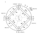
図1は回転子1の軸P(後述)に垂直な断面を示す。ここに例示されるように、回転子1は回転子用コア10と複数の永久磁石20とを備えている。
First embodiment.
<Configuration of rotor>
FIG. 1 shows a cross section perpendicular to an axis P (described later) of the
複数の永久磁石20は例えば希土類磁石(例えばネオジム、鉄、ホウ素を主成分とした希土類磁石)であって、所定の軸Pの周りで環状に並んで配置される。図1の例示では、各永久磁石20は直方体状の板状形状を有している。各永久磁石20は、軸Pを中心とした周方向(以下、単に周方向と呼ぶ)における自身の中央において、その厚み方向が、軸Pを中心とした径方向(以下、単に径方向と呼ぶ)に沿う姿勢で配置されている。なお、各永久磁石20は必ずしも図1に示す形状で配置される必要はない。各永久磁石20は、例えば軸Pに沿う方向(以下、単に軸方向と呼ぶ)に見て、軸Pとは反対側(以下、外周側とも呼ぶ)若しくは軸P側(以下、内周側とも呼ぶ)へと開口するV字形状、又は外周側若しくは内周側へと開口する円弧状の形状を有していてもよい。
The plurality of
また図1の例示では、周方向で隣り合う任意の一対の永久磁石20は外周側へと互いに異なる極性の磁極面20aを向けて配置される。これにより各永久磁石20は、図示せぬ固定子へと界磁磁束を供給する、いわゆる界磁磁石として機能する。
In the illustration of FIG. 1, any pair of
なお図1の例示では4つの永久磁石20(いわゆる4極の回転子1)が例示されているが、回転子1は2個の永久磁石20を有していてもよく、6個以上の永久磁石20を有していてもよい。また図1の例示では、4つの永久磁石20の各々が一つの界磁磁極を構成しているが、例えば一つの界磁磁極が複数の永久磁石20によって構成されていてもよい。言い換えれば、例えば図1における各永久磁石20がそれぞれ複数の永久磁石に分割されていてもよい。
In the illustration of FIG. 1, four permanent magnets 20 (so-called four-pole rotor 1) are illustrated, but the
回転子用コア10は軟磁性体(例えば鉄)で構成されている。図1の例示では、回転子用コア10は例えば軸Pを中心とした略円柱状の形状を有している。
The
回転子用コア10には複数の永久磁石20が格納される複数の磁石格納孔12が穿たれている。各磁石格納孔12は各永久磁石20の形状及び配置に合わせた形状を有している。図1の例示では、4つの磁石格納孔12が穿たれている。
The
各永久磁石20によって、回転子用コア10の外周側面11には、軸の周りで交互に異なる極性の磁極を径方向に向かって呈する2p(pは1以上の整数)個の磁極面が形成される。図1の例示では、正極の磁極面20aを呈する2つの永久磁石20がそれぞれ外周側面11に正極の磁極面を形成し、負極の磁極面20aを呈する2つの永久磁石20がそれぞれ外周側面11に負極の磁極面を形成する。よって図1の例示では外周側面11には4つの磁極面が形成される。
Each
回転子用コア10は例えば軸方向に積層された電磁鋼板で構成されてもよい。これにより回転子用コア10の軸方向における電気抵抗を高めることができ、以って回転子用コア10を流れる磁束に起因した渦電流の発生を低減することができる。また回転子用コア10は、意図的に電気的絶縁物(例えば樹脂)を含んで形成される圧粉磁心によって構成されてもよい。絶縁物が含まれているので圧粉磁心の電気抵抗は比較的高く、以って渦電流の発生を低減できる。
The
回転子用コア10には例えば軸Pを中心とした略円柱状のシャフト用貫通孔13が設けられていてもよい。シャフト用貫通孔13を形成する側面は、外周側面11に対して内周側側面と把握できる。かかるシャフト用貫通孔13に不図示のシャフトを嵌合させて回転子用コア10とシャフトとが固定される。またシャフト用貫通孔13が設けられない場合は、例えば軸方向における回転子用コア10の両側に端板(不図示)を設け、当該端板にシャフトを取り付ければよい。
The
図1の例示では、回転子用コア10には一の界磁磁極を形成する永久磁石20の周方向における両側で空隙121が穿たれている。空隙121は永久磁石20の両側から外周側へと延在している。空隙121によって、永久磁石20の外周側の磁極面20aと内周側の磁極面20bとの間で磁束が短絡することを抑制できる。
In the illustration of FIG. 1, the
図1の例示では空隙121は磁石格納孔12と連結されているが、磁石格納孔12と離間していてもよい。この場合、空隙121と磁石格納孔12との間には回転子用コア10の一部が介在するので、回転子用コア10の強度を向上できる。
In the illustration of FIG. 1, the
図1の例示では、周方向で隣り合う永久磁石20同士の間には回転子用コア10の一部としてのリブ部14が介在している。かかるリブ部14はいわゆるq軸リラクタンスを向上することができる。よって、d軸リラクタンスとq軸リラクタンスとの差を増大でき、ひいてはリラクタンストルクを向上できる。
In the illustration of FIG. 1, a
図1の例示では、リブ部14と、永久磁石20の外周側に存するコア部(回転子用コア10の一部)とは、空隙121の外周側にて相互に連結されている。かかる連結部15も回転子用コア10の一部として形成される。これにより、回転子用コア10の強度を向上することができる。なお、この連結部の径方向における厚みは、当該連結部を通る磁束によって容易に磁気飽和する程度に小さいことが望ましい。これにより、永久磁石20の磁極面20a,20bの間で磁束が、永久磁石20の外周側のコア部、連結部15、リブ部14、永久磁石20の内周側のコア部(回転子用コア10の一部)を経由して短絡することを防止できる。
In the illustration of FIG. 1, the
回転子用コア10には磁気障壁部111が設けられている。磁気障壁部111は永久磁石20に対して外周側面11側に設けられる。図1の例示では磁気障壁部111は外周側面11に形成された溝部112として示されている。図1の例示では、溝部112は、周方向に沿った面112aと、当該面112aの周方向における両端から径方向の外周側へと延在する面112bとを有し、面112bは面112aと反対側で溝部112以外の外周側面11と連結している。
The
軸Pの周りを角度で((p+1)×2)等分した領域の各々に、少なくとも一つの磁気障壁部111(図1の例示では溝部112)が設けられている。図1ではかかる領域の一例が、軸Pを中心とした放射状の二点破線のうち隣り合う二者で挟まれる領域として示されている。 At least one magnetic barrier portion 111 (in the example of FIG. 1, a groove portion 112) is provided in each of the regions equally divided by the angle around the axis P ((p + 1) × 2). In FIG. 1, an example of such a region is shown as a region sandwiched between two adjacent members out of a radial two-dot broken line centered on the axis P.
図1の例示では、磁気障壁部111は、回転子1の磁極の対の数(以下、極対数と呼ぶ)pに1を加えた値を2倍して算出される個数、設けられる。なお回転子1の極対数pは、回転子用コア10の外周側面11に形成される磁極面の対の数と把握することができる。図1の例示では、回転子1の極対数pは2であるので6(=(2+1)×2)個の磁気障壁部111が設けられている。
In the example of FIG. 1, the
本回転子1に対して、径方向においてエアギャップを介して外周側面11と対面するように固定子(不図示)を配置することで回転電機を実現できる。しかも本回転子1によれば、例えば固定子が有するコイルへと電流を流して回転子1を回転させた場合の、回転子1の振れ回りに起因した振動を低減することができる。以下、振れ回りに起因する磁束密度について説明し、次に振動の低減について具体的に説明する。
A rotating electrical machine can be realized by disposing a stator (not shown) so as to face the outer
<振れ回りに起因する磁束密度>
回転子1は理想的には回転軸Pを中心とした回転動作を行うものの、実際には例えば回転子1の中心と固定子の中心との間に差が生じることにより、回転子1は軸Pを中心とした振れ回りも並行して行う。ここでいう回転動作とは軸Pを中心とした回転子1の自転動作であり、振れ回りとは回転子1の中心が軸Pを中心として回転する公転動作をいう。
<Magnetic flux density due to swing>
Although the
そして、この振れ回りにより回転子1と固定子との間のエアギャップが変動する。例えば図2に示すように、回転子1の中心Q1が固定子の中心Q2よりも紙面下方向にずれている場合のエアギャップについて考察する。なお、図2においては回転子1をより簡略化して示し、また固定子の回転子1に対向する面を破線で示している。また回転子1の中心Q1と固定子の中心Q2とのずれは実際には0.1mm程度であるものの、かかるずれを誇張して示している。
The air gap between the
図2に示すように、エアギャップは紙面上側で最も大きく、紙面下側で最も小さく、紙面左右方向における回転子1の中心Q1と固定子の中心Q2との位置が一致した際のエアギャップとほぼ一致する。
As shown in FIG. 2, the air gap is largest in the upper side, smallest lower side, and the air gap when the position of the center Q2 of the center Q1 of the
次に、回転子1が回転する場合に、例えば紙面最上に位置する点Aを通る位置でのエアギャップの変化について考察する。初期的には、点Aにおけるエアギャップは最大値を採る。そして、回転子1が例えば反時計回りに振れ回りを伴って回転することにより、点Aにおけるエアギャップは減少する。そして回転角で90度回転したときに、図3に示すように、点Aにおけるエアギャップは、回転子1の中心Q1と固定子の中心Q2とが互いに一致したときのエアギャップと略一致する。
Next, when the
続く回転によっても点Aにおけるエアギャップは減少する。そして回転角で180度回転したときに図4に示すように、点Aにおけるエアギャップは最小値を採る。続く回転によって点Aにおけるエアギャップは増大する。そして回転角で270度回転したときに図5に示すように、点Aにおけるエアギャップは回転子1の中心Q1と固定子の中心Q2とが互いに一致したときのエアギャップと略一致する。続く回転によっても点Aにおけるエアギャップが増大し、回転角で360度、回転したときに再び最大値を採る。
The air gap at point A also decreases with subsequent rotation. Then, as shown in FIG. 4, when the air is rotated 180 degrees at the rotation angle, the air gap at the point A takes the minimum value. Subsequent rotation increases the air gap at point A. Then, as shown in FIG. 5 when rotated 270 degrees rotation angle, the air gap at the point A substantially coincides with the air gap when the center Q2 of the stator and the center Q1 of the
かかる点Aにおけるエアギャップの変動から理解できるように、点Aにおけるエアギャップは回転角で360度を1周期とする余弦波成分を多く有する。 As can be understood from the fluctuation of the air gap at the point A, the air gap at the point A has many cosine wave components having a rotation angle of 360 degrees as one cycle.
またエアギャップが増大するに従って磁気抵抗が増大することに鑑みると、回転子1の振れ回りに起因してパーミアンスはエアギャップの変動と同様に変動する。したがって、点Aにおけるエアギャップの変動を余弦波成分で把握すると、点Aを通るパーミアンスRmを次式で表すことができる。
In view of the fact that the magnetic resistance increases as the air gap increases, the permeance fluctuates similarly to the fluctuation of the air gap due to the swing of the
Rm=1+a・cosθ ・・・(1) Rm = 1 + a · cos θ (1)
ただし、回転子1の中心Q1と固定子の中心Q2とが一致している場合のパーミアンスを1に規格化している。またaは回転子の中心Q1と固定子の中心Q2とのずれに起因する値である。aは回転子1の中心Q1と固定子の中心Q2とのずれが大きいほど大きくなる。
However, the permeance when the center Q1 of the
回転子1の中心Q1と固定子の中心Q2とが一致している場合の、回転動作に起因する起磁力B1は次式で表される。
When the center Q1 of the
B1=cos(pθ) ・・・(2) B1 = cos (pθ) (2)
なお、簡単のためにパーミアンスRmと、起磁力B1との位相差をゼロとしている。また起磁力B1は磁束密度の振幅を1に規格化して把握されている。 For simplicity, the phase difference between the permeance Rm and the magnetomotive force B1 is set to zero. The magnetomotive force B1 is grasped by standardizing the amplitude of the magnetic flux density to 1.
そして、点Aにおいて回転子1と固定子との間を流れる磁束密度B2は、回転動作に起因する起磁力B1と、振れ回りに起因して変動するパーミアンスRmとの積で表される。
The magnetic flux density B2 flowing between the
B2=Rm・B1
=(1+a・cosθ)cos(pθ)
=cos(pθ)
+a/2・{cos(p+1)θ+cos(p−1)θ} ・・・(3)
B2 = Rm · B1
= (1 + a · cos θ) cos (pθ)
= Cos (pθ)
+ A / 2 · {cos (p + 1) θ + cos (p−1) θ} (3)
式(3)の右辺で示すcos(pθ)は回転動作に起因する磁束密度である。式(3)の右辺で示すa{cos(p+1)θ+cos(p−1)θ}は振れ回りに起因する磁束密度である。回転子1が定常的に回転しているとき、回転子と固定子のそれぞれの対称性から、値aは角度θに依存せずに一定値を採ると考えられるので、磁束密度B2には振れ回りに起因して、回転角360度を1周期とする余弦波を基本波とする(p±1)次の高調波成分が生じる。
The cos (pθ) shown on the right side of the equation (3) is the magnetic flux density resulting from the rotation operation. A {cos (p + 1) θ + cos (p−1) θ} shown on the right side of the equation (3) is a magnetic flux density caused by swinging. When the
なお、ここではパーミアンスRmと磁束密度B1との位相差をゼロと仮定したが、この位相差をφとして計算したとしても磁束密度B2には(p±1)次の高調波成分が生じることが導ける。 Here, it is assumed that the phase difference between the permeance Rm and the magnetic flux density B1 is zero. However, even if this phase difference is calculated as φ, a (p ± 1) -order harmonic component may be generated in the magnetic flux density B2. I can guide.
また式(2)に示すように振れ回りに起因するパーミアンスRmをcosθで表したが、実際には複数の次数の高調波成分を有する。よって実際には磁束密度B2にはn次の高調波成分を含んでいるものの、式(2)のようにパーミアンスRmの変動の主な成分はcosθで表せるので、磁束密度B2はp次、(p±1)次の高調波成分を他の次数の高調波成分に比べてより多く含む。 Further, as shown in the equation (2), the permeance Rm caused by the swinging is expressed by cos θ, but actually has a plurality of harmonic components. Therefore, although the magnetic flux density B2 actually includes an nth-order harmonic component, the main component of fluctuation of the permeance Rm can be expressed by cos θ as shown in the equation (2). p ± 1) It contains more harmonic components than the other harmonic components.
p次の高調波成分は回転子1の回転動作に起因して生じるものであり、回転電機のトルクに寄与し、振動の増大を招来しない成分である。これ以外の高調波成分は、径方向の電磁加振力の因子となって振動を招来しえる成分である。特に、pとp+1との和(2p+1)を次数とする電磁加振力は、振動を増大させる比較的大きな要因となる。かかる見解は本願出願人が実験的に確認している。そして(2p+1)次の電磁加振力は、p次の高調波成分と、(p+1)次の高調波成分とを因子として計算される。
The p-order harmonic component is generated due to the rotational operation of the
<振動の低減>
図1に示す回転子1においては、{(p+1)×2}個の磁気障壁部111が、軸Pの周りを角度で{(p+1)×2}等分された領域にそれぞれ設けられている。よって(p+1)次の高調波成分の周期に対応する位置の近辺に、磁気障壁部111が設けられる。磁気障壁部111は磁気抵抗の増大を招くので、磁束密度B2のうち(p+1)次の高調波成分をバランスよく低減することができる。
<Reducing vibration>
In the
図1の例示では、磁気障壁部111が周方向で略等間隔に設けられている。これにより、磁気障壁部111は(p+1)次の高調波成分の周期に対応して設けられる。磁気障壁部111の位置が(p+1)次の高調波成分の山と谷とに相当する位置に一致していれば、(p+1)次の高調波成分を最も低減することができる。
In the illustration of FIG. 1, the
以上のように、(p+1)次の高調波成分をバランスよく低減できるので、p次の高調波成分と(p+1)次の高調波成分とによって生じる(2p+1)次の電磁加振力を低減でき、他の次数の高調波成分を低減するよりも振動を効率的に低減することができる。 As described above, since the (p + 1) -order harmonic component can be reduced in a balanced manner, the (2p + 1) -order electromagnetic excitation force generated by the p-order harmonic component and the (p + 1) -order harmonic component can be reduced. The vibration can be efficiently reduced as compared with the reduction of other order harmonic components.
図6には、磁束密度B2の2乗(即ち径方向の電磁加振力)について、5次の電磁加振力の一例が示されている。図6の例示では、磁気障壁部111を有さない回転子についての5次の電磁加振力が実線で示され、図1の回転子1についての5次の電磁加振力が破線で示されている。図6に示されるように、磁気障壁部111を有する回転子1によれば、5次の電磁加振力を低減することができる。図6の例示では、5次の電磁加振力の振幅が約1割強、低減されている。
FIG. 6 shows an example of a fifth-order electromagnetic excitation force with respect to the square of the magnetic flux density B2 (that is, the radial electromagnetic excitation force). In the illustration of FIG. 6, the fifth-order electromagnetic excitation force for the rotor that does not have the
図7には、磁束密度B2のうちトルクに寄与する成分(ここでは2次の高調波成分)の一例が示されている。図7の例示では、磁気障壁部111を有さない回転子についての磁束密度B1が実線で示され、図1の回転子1についての磁束密度B1が破線で示されている。図7に示されるように、磁気障壁部111を有する回転子1によれば、トルクに寄与する成分の振幅はほとんど低減していない。
FIG. 7 shows an example of a component (here, a second harmonic component) that contributes to the torque in the magnetic flux density B2. In the illustration of FIG. 7, the magnetic flux density B1 for the rotor that does not have the
以上のように、本回転子1によれば、磁気障壁部111を有さない回転子に比して、トルクに寄与する成分の振幅の低減を抑制しつつも、5次の電磁加振力を低減することができる。5次の電磁加振力は回転子1の振れ回りに起因して生じて振動の増大させる主要因となるところ、本回転子1によれば5次の電磁加振力を低減できるので効率的に振動を低減することができる。また、振動を低減しつつも、トルクに寄与する成分の振幅の低下を抑制するので、トルクの低下を抑制できる。
As described above, according to the
なお、上述したように、回転子1の振れ回りに起因して磁束密度B2は(p±1)次の高調波成分を含む。図1の回転子1では((p+1)×2)個の磁気障壁部111が回転子用コア10に設けられているので、(p+1)次の高調波成分をバランスよく低減できる。一方、((p−1)×2)個の磁気障壁部111が回転子用コア10に設けられることで、(p−1)次の高調波成分をバランスよく低減することができる。(p−1)次の高調波成分によっても径方向の電磁加振力が増大されて振動の増大を招くところ、この場合であれば、(p−1)次の高調波成分を低減できるので振動を低減することはできる。しかも、式(2)より理解できるように、磁束密度B2は比較的振幅の大きい(p−1)次の高調波成分を含むので、これを低減できることにより振動を効率的に低減できる。ただし、上述したように、(2p+1)次の電磁加振力が大きく振動に影響するので、(p+1)次の高調波成分を低減する場合に比べて、振動の低減効果は低い。
As described above, the magnetic flux density B2 includes (p ± 1) order harmonic components due to the swing of the
また、(p±1)次の高調波成分に応じて、(((p+1)×2)+((p−1)×2))個の磁気障壁部111が回転子用コア10に設けられていてもよい。この場合、(p±1)次の高調波成分を低減でき、以ってさらに振動を低減できる。なお、(p+1)次の高調波成分に対応する磁気障壁部111のいくつかと、(p−1)次の高調波成分に対応する磁気障壁部111のいくつかとが、周方向で同じ位置に設けられる場合、これらの各々については一つの磁気障壁部111が当該位置に設けられればよい。
Further, (((p + 1) × 2) + ((p−1) × 2))
以下では磁気障壁部111として他の態様を例示するが、磁気障壁部111の個数及び周方向における位置については第1の実施の形態と同様であるので、詳細な説明は省略する。
In the following, other modes are exemplified as the
第2の実施の形態.
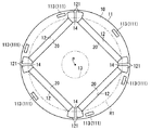
図8に示す回転子1は、図1に示す回転子1と比較して磁気障壁部111が相違している。
Second embodiment.
The
磁気障壁部111は孔113として示されている。孔113はその内部を流体、例えば空気や冷媒が充填されているので磁気障壁として機能することができる。孔113は、回転子用コア10の外周側面11と永久磁石20との間(より具体的には、永久磁石20を通る円環と外周側面11との間)に設けられる。なお磁気障壁部111は孔113に限らず、孔113に非磁性体が充填されていてもよい。非磁性体が充填されていれば回転子1の強度を向上できる。
The
図8の例示では、磁気障壁部111(孔113)は軸方向に沿って見て長尺状の形状を有し、その長辺が周方向に接するように配置されている。回転子用コア10に空隙121が穿たれる場合であれば、図8に示すように磁気障壁部111は空隙121を避けて設けられてもよい。
In the illustration of FIG. 8 , the magnetic barrier portion 111 (hole 113) has a long shape when viewed in the axial direction, and is arranged so that its long side is in the circumferential direction. If the
かかる磁気障壁部111であっても第1の実施の形態と同様に回転子1の振れ回りに起因する振動を低減することができる。また本磁気障壁部111は外周側面11と永久磁石20との間に設けられるので、外周側面11には溝が形成される必要がない。よって、外周側面11の周方向のいずれの位置においてもエアギャップを測定することができる。換言すれば、磁気障壁部111がエアギャップの測定を阻害しない。よって、エアギャップ測定の作業性を向上することができる。
Even with such a
磁気障壁部111はその径方向における位置が外周側面11に近い方が好ましい。図9は、回転子1の中心Q2から磁気障壁部111までの距離と、磁束密度B2のトルクに寄与する成分(2次高調波成分)に対する3次高調波成分の比との関係を示している。図10においては、中心Q2に対する外周側面11の半径が29.8mmである回転子1についての結果である。なおグラフにおいて中心Q2と磁気障壁部111との距離が29.8mmとして示されたデータは回転子用コア10に磁気障壁部111が設けられない場合を示している。
The
図9に示すように、磁気障壁部111は外周側面11に近いほど3次高調波成分を低減できる。そして、磁気障壁部111が永久磁石20の外接円R1と外周側から接する位置(中心Q2と磁気障壁部111との距離が外接円R1の半径)であるときの、トルクに寄与する成分に対する3次高調波成分は、磁気障壁部111が設けられないときのそれと一致している。よって、磁気障壁部111は永久磁石20の外接円R1と外周側面11との間に位置することが要求される。
As shown in FIG. 9 , the
なお、第1の実施の形態と同様に、空隙121を磁気障壁部111として把握しても良い。図8の例示でいえば、例えば空隙121と近接する4つの孔113を設けずに、空隙121を磁気障壁部111として把握しても良い。
Note that the
第3の実施の形態.
図10に示す回転子1は、図1に示す回転子1と比較して磁気障壁部111が相違している。
Third embodiment.
The
回転子用コア10は軸方向に積層された複数の電磁鋼板により構成されている。複数の電磁鋼板は、それぞれに設けられた凹凸が軸方向で嵌合しあって相互に固定される。かかる凹凸は、軸方向に沿って所定の部材を電磁鋼板に押し込むことで一方の面に凹部を形成するとともに同じ位置の他方の面に凸部を形成して、設けられる。このように凹凸は電磁鋼板の変形によって形成される。よって凹凸の磁気特性は劣化する。また、一の電磁鋼板の凸部とこれと軸方向で接する凹部とは完全に連続しないので、この境界でも磁気特性が劣化する。
The
かかる磁気特性の劣化を考慮して、図10に示す回転子1では、磁気障壁部111として電磁鋼板を相互に固定する凹凸114を採用している。凹凸114は、その周方向における位置が第1の実施の形態で説明したように、その径方向における位置が第2の実施の形態で説明したように設けられる。ただし、凹凸114の磁気障壁としての能力が孔113の磁気障壁としての能力よりも小さい場合は、永久磁石20の外接円R1よりも更に外周側面11側に位置するほうがよい。
In consideration of the deterioration of the magnetic characteristics, the
これにより、回転子1の振動を低減できるとともに、第2の実施の形態と同様にエアギャップ測定の作業性を向上することができる。しかも、磁気障壁部111は複数の電磁鋼板同士を固定する機能と、振動低減のための磁気障壁の機能とを発揮するので、それぞれの機能を発揮する専用の固定部、磁気障壁部を設ける場合に比べて、製造コストを低減できる。
Thereby, the vibration of the
なお、第1の実施の形態と同様に、空隙121を磁気障壁部111として把握しても良い。図10の例示でいえば、空隙121と近接する4つの凹凸114を設けずに、空隙121を磁気障壁部111として把握しても良い。ただし、電磁鋼板同士を固定する凹凸114はその個数が多いほど電磁鋼板を固定する力が大きいので、ある程度の個数を設けることが望ましい。
Note that the
第4の実施の形態.
第1乃至第3の実施の形態で説明した回転子1は例えば密閉型圧縮機用のモータに用いられる。図11は、上記のモータが適用される圧縮機の縦断面図である。図11に示された圧縮機は高圧ドーム型のロータリ圧縮機であって、その冷媒には例えば二酸化炭素が採用される。なお図11においてはアキュムレータK100も図示されている。
Fourth embodiment.
The
この圧縮機は、密閉容器K1と、圧縮機構部K2と、モータK3とを備えている。圧縮機構部K2は密閉容器K1内に配置されている。モータK3は密閉容器K1内かつ圧縮機構部K2の上側に配置される。ここで、上側とは密閉容器K1の中心軸が水平面に対して傾斜しているか否かに関わらず、密閉容器K1の中心軸に沿った上側をいう。 This compressor includes a hermetic container K1, a compression mechanism K2, and a motor K3. The compression mechanism K2 is disposed in the sealed container K1. The motor K3 is disposed in the sealed container K1 and above the compression mechanism K2. Here, the upper side means the upper side along the central axis of the sealed container K1, regardless of whether the central axis of the sealed container K1 is inclined with respect to the horizontal plane.
モータK3は回転シャフトK4を介して圧縮機構部K2を駆動する。モータK3は回転子1と固定子3とを備えている。
The motor K3 drives the compression mechanism part K2 via the rotating shaft K4. The motor K3 includes a
密閉容器K1の下側側方には吸入管K11が接続され、密閉容器K1の上側には吐出管K12が接続される。アキュムレータK100からの冷媒ガス(図示省略)が吸入管K11を経由して密閉容器K1へと供給され、圧縮機構部K2の吸込側に導かれる。このロータリ圧縮機は縦型であって、少なくともモータK3の下部に油溜めを有する。 A suction pipe K11 is connected to the lower side of the sealed container K1, and a discharge pipe K12 is connected to the upper side of the sealed container K1. Refrigerant gas (not shown) from the accumulator K100 is supplied to the sealed container K1 via the suction pipe K11 and guided to the suction side of the compression mechanism K2. This rotary compressor is a vertical type, and has an oil sump at least under the motor K3.
固定子3は、回転シャフトK4に対して回転子1よりも外周側に配置され、密閉容器K1に固定されている。
The stator 3 is disposed on the outer peripheral side of the
圧縮機構部K2は、シリンダ状の本体部K20と、上端板K8および下端板K9を備える。上端板K8および下端板K9はそれぞれ本体部K20の上下の開口端に取り付けられる。回転シャフトK4は、上端板K8および下端板K9を貫通し、本体部K20の内部に挿入されている。回転シャフトK4は上端板K8に設けられた軸受K21と、下端板K9に設けられた軸受K22により回転自在に支持されている。 The compression mechanism K2 includes a cylindrical main body K20, an upper end plate K8, and a lower end plate K9. The upper end plate K8 and the lower end plate K9 are respectively attached to the upper and lower open ends of the main body K20. The rotation shaft K4 passes through the upper end plate K8 and the lower end plate K9, and is inserted into the main body K20. The rotary shaft K4 is rotatably supported by a bearing K21 provided on the upper end plate K8 and a bearing K22 provided on the lower end plate K9.
回転シャフトK4には本体部K20内でクランクピンK5が設けられる。ピストンK6はクランクピンK5に嵌合されて駆動される。ピストンK6と、これに対応するシリンダとの間には圧縮室K7が形成される。ピストンK6は偏芯した状態で回転し、または、公転運動を行い、圧縮室K7の容積を変化させる。 The rotation shaft K4 is provided with a crank pin K5 in the main body K20. The piston K6 is fitted to the crank pin K5 and driven. A compression chamber K7 is formed between the piston K6 and the corresponding cylinder. The piston K6 rotates in an eccentric state or revolves to change the volume of the compression chamber K7.
次に、上記ロータリ圧縮機の動作を説明する。アキュムレータK100から吸入管K11を経由して圧縮室K7に冷媒ガスが供給される。モータK3により圧縮機構部K2が駆動されて、冷媒ガスが圧縮される。圧縮された冷媒ガスは冷凍機油(図示省略)と共に、吐出孔K23を経由して圧縮機構部K2から圧縮機構部K2の上側へ運ばれ、更にモータK3を経由して吐出管K12から密閉容器K1の外部に吐出される。 Next, the operation of the rotary compressor will be described. Refrigerant gas is supplied from the accumulator K100 to the compression chamber K7 via the suction pipe K11. The compression mechanism K2 is driven by the motor K3, and the refrigerant gas is compressed. The compressed refrigerant gas is transported together with refrigerating machine oil (not shown) from the compression mechanism K2 to the upper side of the compression mechanism K2 via the discharge hole K23, and further from the discharge pipe K12 to the sealed container K1 via the motor K3. Is discharged to the outside.
冷媒ガスは冷凍機油と共にモータK3の内部を上側へと移動する。冷媒ガスはモータK3よりも上側に導かれるが、冷凍機油は回転子1の遠心力で密閉容器K1の内壁へと向かう。冷凍機油は密閉容器K1の内壁に微粒子の状態で付着することで液化した後、重力の作用によって、モータK3の冷媒ガスの流れの上流側に戻る。
The refrigerant gas moves upward in the motor K3 together with the refrigerating machine oil. The refrigerant gas is guided to the upper side of the motor K3, but the refrigerating machine oil moves toward the inner wall of the sealed container K1 by the centrifugal force of the
かかる密閉型圧縮機において、モータK3の回転子1として第1乃至第3の回転子1を採用することで、回転子1の振動ひいては密閉型圧縮機の振動を低減することができる。
In such a hermetic compressor, by employing the first to
1 回転子
10 回転子用コア
20 永久磁石
111 磁気障壁部
112 溝部
113 孔
114 凹凸
121 空隙
DESCRIPTION OF
Claims (5)
前記永久磁石によって前記軸の周りで交互に異なる極性の磁極が、前記軸を中心とした径方向に向かって呈された2N(Nは自然数)個の磁極面(11)と、前記永久磁石に対して前記磁極面側に設けられ、前記軸の周りを角度で((N+1)×2)等分した領域の各々に少なくとも一つ存する磁気障壁部(111)とを有する回転子用コア(10)と
を備え、
前記領域にそれぞれ存在する((N+1)×2)個の前記磁気障壁部は、前記軸(P)を中心とした周方向において互いに等間隔に設けられ、
前記磁気障壁部は前記周方向において前記永久磁石の前記周方向の両端に設けられる空隙(121)とは異なる、回転子。 A permanent magnet (20) arranged annularly around a predetermined axis (P);
Magnetic poles having different polarities alternately around the axis by the permanent magnet are provided in 2N (N is a natural number) magnetic pole surfaces (11) that are presented in a radial direction around the axis, and the permanent magnet On the other hand, the rotor core (10) is provided on the magnetic pole face side, and has at least one magnetic barrier portion (111) in each of the regions ((N + 1) × 2) equally divided by the angle around the axis. ) and equipped with a,
The ((N + 1) × 2) magnetic barrier portions respectively present in the region are provided at equal intervals in the circumferential direction around the axis (P),
The magnetic barrier portion is a rotor that is different from air gaps (121) provided at both ends of the permanent magnet in the circumferential direction in the circumferential direction .
前記軸(P)に沿う方向に積層された複数の電磁鋼板
を更に有し、
前記複数の電磁鋼板の少なくとも複数枚には相互に嵌合して前記軸に沿った方向における固定のために凹凸(114)が設けられ、当該凹凸は前記磁気障壁部(111)として機能する、請求項1に記載の回転子。 The rotor core is
A plurality of electrical steel sheets laminated in a direction along the axis (P)
Further comprising
At least a plurality of the plurality of electromagnetic steel plates are fitted with each other and provided with unevenness (114) for fixing in the direction along the axis, and the unevenness functions as the magnetic barrier portion (111). The rotor according to claim 1 .
Priority Applications (7)
| Application Number | Priority Date | Filing Date | Title |
|---|---|---|---|
| JP2009172013A JP4661972B2 (en) | 2009-07-23 | 2009-07-23 | Rotor |
| US13/386,130 US8803395B2 (en) | 2009-07-23 | 2010-07-09 | Rotor |
| CN201080026933.8A CN102474141B (en) | 2009-07-23 | 2010-07-09 | Rotor |
| EP10802185.8A EP2458713A4 (en) | 2009-07-23 | 2010-07-09 | Rotor |
| PCT/JP2010/061688 WO2011010565A1 (en) | 2009-07-23 | 2010-07-09 | Rotor |
| AU2010274456A AU2010274456B2 (en) | 2009-07-23 | 2010-07-09 | Rotor |
| KR1020117030845A KR101278008B1 (en) | 2009-07-23 | 2010-07-09 | Rotor |
Applications Claiming Priority (1)
| Application Number | Priority Date | Filing Date | Title |
|---|---|---|---|
| JP2009172013A JP4661972B2 (en) | 2009-07-23 | 2009-07-23 | Rotor |
Related Child Applications (1)
| Application Number | Title | Priority Date | Filing Date |
|---|---|---|---|
| JP2010253604A Division JP5120440B2 (en) | 2010-11-12 | 2010-11-12 | Rotor |
Publications (2)
| Publication Number | Publication Date |
|---|---|
| JP2011030325A JP2011030325A (en) | 2011-02-10 |
| JP4661972B2 true JP4661972B2 (en) | 2011-03-30 |
Family
ID=43638402
Family Applications (1)
| Application Number | Title | Priority Date | Filing Date |
|---|---|---|---|
| JP2009172013A Active JP4661972B2 (en) | 2009-07-23 | 2009-07-23 | Rotor |
Country Status (1)
| Country | Link |
|---|---|
| JP (1) | JP4661972B2 (en) |
Cited By (2)
| Publication number | Priority date | Publication date | Assignee | Title |
|---|---|---|---|---|
| JP2011030427A (en) * | 2010-11-12 | 2011-02-10 | Daikin Industries Ltd | Rotor |
| US8803395B2 (en) | 2009-07-23 | 2014-08-12 | Daikin Industries, Ltd. | Rotor |
Families Citing this family (3)
| Publication number | Priority date | Publication date | Assignee | Title |
|---|---|---|---|---|
| JP5720445B2 (en) * | 2011-07-07 | 2015-05-20 | ダイキン工業株式会社 | Rotating electric machine |
| JP5783898B2 (en) * | 2011-12-28 | 2015-09-24 | 日立アプライアンス株式会社 | Permanent magnet motor and compressor |
| CN114640226B (en) * | 2022-03-09 | 2024-03-26 | 上海电机系统节能工程技术研究中心有限公司 | Design method of dipolar motor rotor punching sheet |
Citations (3)
| Publication number | Priority date | Publication date | Assignee | Title |
|---|---|---|---|---|
| JP2002252947A (en) * | 2001-02-26 | 2002-09-06 | Hitachi Ltd | Dynamo electric machine and electric vehicle using the same |
| JP2005176424A (en) * | 2003-12-08 | 2005-06-30 | Nissan Motor Co Ltd | Rotor for dynamo-electric machine |
| JP2009027852A (en) * | 2007-07-20 | 2009-02-05 | Mitsui High Tec Inc | Rotor laminated core for reluctance motor |
-
2009
- 2009-07-23 JP JP2009172013A patent/JP4661972B2/en active Active
Patent Citations (3)
| Publication number | Priority date | Publication date | Assignee | Title |
|---|---|---|---|---|
| JP2002252947A (en) * | 2001-02-26 | 2002-09-06 | Hitachi Ltd | Dynamo electric machine and electric vehicle using the same |
| JP2005176424A (en) * | 2003-12-08 | 2005-06-30 | Nissan Motor Co Ltd | Rotor for dynamo-electric machine |
| JP2009027852A (en) * | 2007-07-20 | 2009-02-05 | Mitsui High Tec Inc | Rotor laminated core for reluctance motor |
Cited By (2)
| Publication number | Priority date | Publication date | Assignee | Title |
|---|---|---|---|---|
| US8803395B2 (en) | 2009-07-23 | 2014-08-12 | Daikin Industries, Ltd. | Rotor |
| JP2011030427A (en) * | 2010-11-12 | 2011-02-10 | Daikin Industries Ltd | Rotor |
Also Published As
| Publication number | Publication date |
|---|---|
| JP2011030325A (en) | 2011-02-10 |
Similar Documents
| Publication | Publication Date | Title |
|---|---|---|
| WO2011010565A1 (en) | Rotor | |
| AU2007298344B2 (en) | Motor and compressor | |
| JP4135018B2 (en) | Magnet-embedded rotor, electric motor using the rotor, and compressor using the electric motor | |
| WO2018203364A1 (en) | Rotor, electric motor, compressor, and air conditioning device | |
| JP5120440B2 (en) | Rotor | |
| JP4661972B2 (en) | Rotor | |
| JP2011101544A (en) | Rotary electric machine | |
| WO2010016583A1 (en) | Stator, motor, and compressor | |
| US20070120434A1 (en) | Synchronous reluctance motor and compressor having the same | |
| JP2012080713A (en) | Permanent magnet-type rotary electric machine and compressor using the same | |
| JP5720445B2 (en) | Rotating electric machine | |
| JP6526316B2 (en) | Rotor, electric motor, compressor, and refrigeration air conditioner | |
| JPWO2019043850A1 (en) | Rotor, electric motor, compressor and air conditioner | |
| JP5685952B2 (en) | Rotor | |
| JP5644317B2 (en) | Rotor | |
| JP4661974B2 (en) | Rotor | |
| JP2010041851A (en) | Structure of fixing stator and casing, and compressor equipped with the same | |
| JP5652221B2 (en) | Rotor | |
| JP6641476B2 (en) | Rotor, electric motor and compressor | |
| JP2012139045A (en) | Rotor, motor, and compressor | |
| JP2012223068A (en) | Rotary electric machine | |
| JP2016197991A (en) | Neodymium permanent magnet motor, and hermetic compressor including neodymium permanent magnet motor | |
| WO2020129574A1 (en) | Electric compressor motor, electric compressor provided with same, and method for manufacturing electric compressor motor | |
| JP2013207810A (en) | Rotor | |
| KR20200099849A (en) | Motor and compressor including the same |
Legal Events
| Date | Code | Title | Description |
|---|---|---|---|
| A521 | Written amendment |
Free format text: JAPANESE INTERMEDIATE CODE: A523 Effective date: 20101112 |
|
| TRDD | Decision of grant or rejection written | ||
| A01 | Written decision to grant a patent or to grant a registration (utility model) |
Free format text: JAPANESE INTERMEDIATE CODE: A01 Effective date: 20101207 |
|
| A01 | Written decision to grant a patent or to grant a registration (utility model) |
Free format text: JAPANESE INTERMEDIATE CODE: A01 |
|
| A61 | First payment of annual fees (during grant procedure) |
Free format text: JAPANESE INTERMEDIATE CODE: A61 Effective date: 20101220 |
|
| R151 | Written notification of patent or utility model registration |
Ref document number: 4661972 Country of ref document: JP Free format text: JAPANESE INTERMEDIATE CODE: R151 |
|
| FPAY | Renewal fee payment (event date is renewal date of database) |
Free format text: PAYMENT UNTIL: 20140114 Year of fee payment: 3 |
|
| FPAY | Renewal fee payment (event date is renewal date of database) |
Free format text: PAYMENT UNTIL: 20140114 Year of fee payment: 3 |