JP4660551B2 - Control method of impact rock drilling - Google Patents
Control method of impact rock drilling Download PDFInfo
- Publication number
- JP4660551B2 JP4660551B2 JP2007532915A JP2007532915A JP4660551B2 JP 4660551 B2 JP4660551 B2 JP 4660551B2 JP 2007532915 A JP2007532915 A JP 2007532915A JP 2007532915 A JP2007532915 A JP 2007532915A JP 4660551 B2 JP4660551 B2 JP 4660551B2
- Authority
- JP
- Japan
- Prior art keywords
- limit value
- time
- rotational resistance
- rock
- feed
- Prior art date
- Legal status (The legal status is an assumption and is not a legal conclusion. Google has not performed a legal analysis and makes no representation as to the accuracy of the status listed.)
- Expired - Fee Related
Links
- 239000011435 rock Substances 0.000 title claims abstract description 109
- 238000005553 drilling Methods 0.000 title claims abstract description 91
- 238000000034 method Methods 0.000 title claims abstract description 55
- 230000009471 action Effects 0.000 claims abstract description 12
- 230000003247 decreasing effect Effects 0.000 claims abstract description 4
- 238000009412 basement excavation Methods 0.000 claims 1
- 238000009527 percussion Methods 0.000 abstract 1
- 230000007423 decrease Effects 0.000 description 14
- 230000009467 reduction Effects 0.000 description 12
- 238000007620 mathematical function Methods 0.000 description 4
- 238000005259 measurement Methods 0.000 description 4
- 230000008901 benefit Effects 0.000 description 1
- 230000005540 biological transmission Effects 0.000 description 1
- 238000004422 calculation algorithm Methods 0.000 description 1
- 238000004364 calculation method Methods 0.000 description 1
- 230000008859 change Effects 0.000 description 1
- 238000004590 computer program Methods 0.000 description 1
- 238000005065 mining Methods 0.000 description 1
- 238000012986 modification Methods 0.000 description 1
- 230000004048 modification Effects 0.000 description 1
Images


Classifications
-
- E—FIXED CONSTRUCTIONS
- E21—EARTH OR ROCK DRILLING; MINING
- E21B—EARTH OR ROCK DRILLING; OBTAINING OIL, GAS, WATER, SOLUBLE OR MELTABLE MATERIALS OR A SLURRY OF MINERALS FROM WELLS
- E21B44/00—Automatic control systems specially adapted for drilling operations, i.e. self-operating systems which function to carry out or modify a drilling operation without intervention of a human operator, e.g. computer-controlled drilling systems; Systems specially adapted for monitoring a plurality of drilling variables or conditions
- E21B44/02—Automatic control of the tool feed
- E21B44/04—Automatic control of the tool feed in response to the torque of the drive ; Measuring drilling torque
Landscapes
- Geology (AREA)
- Life Sciences & Earth Sciences (AREA)
- Engineering & Computer Science (AREA)
- Mining & Mineral Resources (AREA)
- Environmental & Geological Engineering (AREA)
- Fluid Mechanics (AREA)
- Physics & Mathematics (AREA)
- General Life Sciences & Earth Sciences (AREA)
- Geochemistry & Mineralogy (AREA)
- Earth Drilling (AREA)
- Drilling And Exploitation, And Mining Machines And Methods (AREA)
- Perforating, Stamping-Out Or Severing By Means Other Than Cutting (AREA)
- Drilling Tools (AREA)
Abstract
Description
本発明は、削岩機へ連結された工具に対して削岩中に衝撃パルスを与える削岩機における衝撃装置を制御し、削岩機の回転装置を制御し、工具は穿孔中にその長手軸を中心に回転し、削岩機を削岩中に削岩すべき岩石に向けて送り出し同様に送り戻す送り装置を制御し、削岩中に、少なくとも回転抵抗を判定し、回転抵抗がその回転抵抗の所定の基準限界値を超えた時の第1の時点を登録し、送りを小さくして回転抵抗の所定の基準限界値に向けて回転抵抗を制御する衝撃式削岩の制御方法に関するものである。 The present invention controls an impact device in a rock drilling machine that gives an impact pulse during rock drilling to a tool connected to the rock drilling machine, controls a rotation device of the rock drilling machine, and the tool has its longitudinal length during drilling. It controls the feeding device that rotates around the axis and feeds the rock drilling machine toward the rock to be drilled during rock drilling. The present invention relates to a control method for impact-type rock drilling that registers a first time point when a predetermined reference limit value of the rotational resistance is exceeded, and controls the rotational resistance toward a predetermined reference limit value of the rotational resistance by reducing the feed. Is.
本発明はさらに、削岩を制御する制御装置においてソフトウエアを実行すると、少なくとも次の動作を提供する衝撃式削岩の制御ソフトウエア製品に関するものである。すなわち、削岩機において、削岩機へ連結されている工具に対して削岩中に衝撃パルスを与える衝撃装置と、削岩中に工具をその長手軸を中心に回転させる回転装置と、削岩中に削岩機を削岩すべき岩石に向けて送り出し同様に送り戻す送り装置とを制御し、さらに、削岩中に、少なくとも回転抵抗を判定し、回転抵抗がその回転抵抗の所定の基準限界値を超えた時の第1の時点を登録し、送りを小さくして回転抵抗の所定の基準限界値に向けて回転抵抗を制御する動作である。 The present invention further relates to an impact rock drilling control software product that provides at least the following operations when the software is executed in a control device for controlling rock drilling. That is, in a rock drill, an impact device that applies an impact pulse during rock drilling to a tool connected to the rock drill, a rotating device that rotates the tool around its longitudinal axis during rock drilling, A rock drill is controlled in the rock to feed the rock to be rocked, and the feed device is fed back in the same manner. Further, during the rock drilling, at least the rotational resistance is determined, and the rotational resistance is a predetermined value of the rotational resistance. In this operation, the first time point when the reference limit value is exceeded is registered, and the rotation resistance is controlled toward a predetermined reference limit value of the rotation resistance by reducing the feed.
さらに本発明はまた、キャリアと、少なくとも1つの送りビームと、この送りビーム上に可動に配設された、少なくとも1つの削岩機と、削岩機を削岩すべき岩石へ向けて送り出し同様に送り戻す送り装置とを含む削岩用掘削装置に関するものであり、削岩機は、この削岩機へ連結された工具に対して衝撃パルスを生成する衝撃装置、および工具をその長手軸を中心に回転させる回転装置を含み、削岩用掘削装置はさらに、少なくとも送り装置、衝撃装置および回転装置の働きを制御装置内の制御方式に従って制御する、少なくとも1つの制御装置と、少なくとも回転抵抗を判定する手段とを含み、制御装置は、回転抵抗がその回転抵抗の所定の基準限界値を超えた時の第1の時点を登録し、送りを小さくして回転抵抗をその回転抵抗の所定の基準限界値へ向けて制御するよう構成されている。 Furthermore, the present invention also provides a carrier, at least one feed beam, at least one rock drill movably disposed on the feed beam, and feeding the rock drill toward the rock to be rocked. The rock drilling machine includes an impact device for generating an impact pulse for a tool connected to the rock drill, and a tool having a longitudinal axis thereof. A rock drilling rig further comprising at least one control device for controlling the operation of at least the feeding device, the impact device and the rotation device in accordance with a control method in the control device, and at least the rotational resistance. A controller for registering a first time point when the rotational resistance exceeds a predetermined reference limit value of the rotational resistance, and reducing the feed so as to reduce the rotational resistance to the predetermined value of the rotational resistance. It is configured to control towards the reference limits.
衝撃式削岩において、いわゆるトルク制御を用いることが知られているが、これは、削岩機の回転モータの回転圧力を削岩機の送り装置の調節で一定に保つことを目的としている。回転トルクが大きくなると、送りを小さくして、再び所望の回転トルクを得る。送りの減少にもかかわらず、回転トルクが小さくならない場合、送り不足の穿孔になってしまう。さらに、ドリルビットが固著してしまうことにもなる。一般に公知のように、送り不足による穿孔に伴う問題は、ドリルビットと岩石との間の接触が少なくなり、これが穿孔力の低下につながる。さらに、送り不足は、穿孔機において引張り応力を生じることになり、これがドリルロッド間の連結部に負荷を与える。 It is known to use so-called torque control in impact rock drilling, and this is intended to keep the rotational pressure of the rotary motor of the rock drilling machine constant by adjusting the feeder of the rock drilling machine. When the rotational torque increases, the feed is reduced and the desired rotational torque is obtained again. If the rotational torque does not decrease despite the reduction in feed, drilling will result in insufficient feed. In addition, the drill bit will be fixed. As is generally known, the problem with drilling due to underfeed is that there is less contact between the drill bit and the rock, which leads to reduced drilling force. Furthermore, insufficient feed results in tensile stress in the drilling machine, which places a load on the connection between the drill rods.
本発明は、新規で改良された削岩制御方法および構造を提供することを目的とする。 It is an object of the present invention to provide a new and improved rock drilling control method and structure.
本発明による方法は、少なくとも制御の第1の限界値および第2の限界値を判定し、これらのうち一方の限界値は時間限界値であり、各限界値に対応する時点における回転抵抗を調節する、少なくとも1つの制御動作を行ない、時間限界値に対応する連続制御動作の開始時点間の時間差を設定し、さらに、回転抵抗が第1の限界値に対応する第2の時点において回転抵抗の基準限界値より大きいと、衝撃力を小さくし、回転抵抗が第2の限界値に対応する第3の時点において回転抵抗の基準限界値より大きいと、送りを停止することを特徴とする。 The method according to the invention determines at least a first limit value and a second limit value of the control, one of which is a time limit value and adjusts the rotational resistance at the time corresponding to each limit value. Performing at least one control action, setting a time difference between the start points of the continuous control action corresponding to the time limit value, and further, at a second time point when the rotational resistance corresponds to the first limit value. If it is larger than the reference limit value, the impact force is reduced, and if the rotation resistance is larger than the reference limit value of the rotation resistance at the third time point corresponding to the second limit value, the feed is stopped.
本発明のソフトウエア製品は、制御装置でのソフトウエア製品の実行によってさらに、少なくとも制御の第1の限界値および第2の限界値を判定し、これらのうち一つの限界値は時間限界値であり、各限界値に対応する時点における回転抵抗を調節する、少なくとも1つの制御動作を行ない、時間限界値に対応する連続制御動作の開始時点間の時間差を設定し、回転抵抗が第1の限界値に対応する第2の時点において回転抵抗の基準限界値より大きいと、衝撃力を小さくし、回転抵抗が第2の限界値に対応する第3の時点において回転抵抗の基準限界値より大きいと、送りを停止するよう構成されていることを特徴とする。 The software product of the present invention further determines at least a first limit value and a second limit value of the control by executing the software product in the control device, and one of the limit values is a time limit value. Yes, at least one control operation is performed to adjust the rotational resistance at the time corresponding to each limit value, and the time difference between the start points of the continuous control operation corresponding to the time limit value is set, and the rotational resistance is the first limit If the rotational resistance is larger than the reference limit value of the rotational resistance at the second time point corresponding to the value, the impact force is reduced, and if the rotational resistance is larger than the reference limit value of the rotational resistance at the third time point corresponding to the second limit value. , And is configured to stop feeding.
本発明による削岩掘削装置は、制御装置が、少なくとも制御の第1の限界値および第2の限界値を判定し、これらの限界値の一つは時間限界値であり、それぞれの限界値に対応する時点における回転抵抗を調節する、少なくとも1つの制御動作を行ない、時間限界値に対応する連続制御動作の開始時点間の時間差を設定し、回転抵抗が第1の限界値に対応する第2の時点において回転抵抗の基準限界値より大きいと、衝撃力を小さくし、回転抵抗が第2の限界値に対応する第3の時点において回転抵抗の基準限界値より大きいと、送りを停止するように構成されていることを特徴とする。 In the rock drilling apparatus according to the present invention, the control device determines at least the first limit value and the second limit value of the control, and one of these limit values is a time limit value, Performing at least one control operation for adjusting the rotational resistance at a corresponding time point, setting a time difference between the start points of the continuous control operation corresponding to the time limit value, and setting a second time corresponding to the first limit value for the rotation resistance. If the rotational resistance is larger than the reference limit value of the rotational resistance at the time point, the impact force is reduced, and if the rotational resistance is larger than the reference limit value of the rotational resistance at the third time point corresponding to the second limit value, the feed is stopped. It is comprised by these.
本発明による第2の削岩掘削装置によれば、制御装置は、制御するために、第1の時点からモニタする、少なくとも1つの時間限界値を判定するように構成され、制御装置は、時間限界値に対応する第2の時点において回転抵抗を調節する、少なくとも1つの制御動作を行なうように構成されていることを特徴とする。 According to a second rock drilling rig according to the invention, the control device is arranged to determine at least one time limit value to monitor from a first time point for control, the control device It is characterized in that it is configured to perform at least one control operation for adjusting the rotational resistance at the second time point corresponding to the limit value.
本発明の主たる概念は、衝撃式削岩において穿孔抵抗を判定し、この穿孔抵抗を所望の穿孔抵抗基準値に保つことにある。穿孔抵抗が基準値を越えた場合、制御方式に従って送りを減少させる。送りを小さくしても第1の限界値に達するまでに回転抵抗が小さくならない場合、制御方式に従って衝撃力を連続して減少させる。さらに、衝撃力の減少によっても第2の限界値に達するまでに回転抵抗が小さくならない場合、次に送りを停止する。第1の限界値および第2の限界値は、圧力、トルク、力、電圧または動力などの物理量でよい。さらに、第1の限界値および第2の限界値は、時間を表す限界値でもよい。本発明において重要なことは、これらの限界値の、少なくとも一つは、常に時間限界値であることである。この時間限界値によって、2つの連続する制御動作の開始時間の時間差を判定する。 The main concept of the present invention is to determine the drilling resistance in the impact type rock drilling and to keep the drilling resistance at a desired drilling resistance reference value. If the drilling resistance exceeds the reference value, the feed is reduced according to the control method. If the rotational resistance does not decrease until the first limit value is reached even if the feed is reduced, the impact force is continuously reduced according to the control method. Further, if the rotational resistance does not decrease until the second limit value is reached even if the impact force decreases, the feeding is then stopped. The first limit value and the second limit value may be physical quantities such as pressure, torque, force, voltage, or power. Further, the first limit value and the second limit value may be limit values representing time. What is important in the present invention is that at least one of these limit values is always a time limit value. Based on this time limit value, the time difference between the start times of two consecutive control operations is determined.
本発明による第2の削岩機の制御系の主たる概念もやはり、穿孔抵抗を所望の穿孔抵抗基準値に保つことである。穿孔抵抗が基準値を超えて、送りを大きくしたにもかかわらず所定の時間中、基準値より大きくなったままでいる場合、削岩機の制御系は、1つ以上の制御動作を行なって、設定した時間限界値に対応する第2の時点において回転抵抗を調節する。 The main concept of the control system of the second rock drill according to the present invention is also to keep the drilling resistance at the desired drilling resistance reference value. If the drilling resistance exceeds the reference value and remains greater than the reference value for a predetermined time despite the increased feed, the rock drill control system performs one or more control actions, The rotational resistance is adjusted at a second time point corresponding to the set time limit value.
本発明の利点は、最大圧力限界値などばかりでなく、時間ベースの限界値を制御系で判定することができるので、削岩を以前より多様に制御することができることである。したがって、制御系は、事前に削岩を制御して、望ましくない最大限界物理量、例えば最大圧力限界値に近づくのを回避することができる。 An advantage of the present invention is that not only the maximum pressure limit value but also the time-based limit value can be determined by the control system, so that rock drilling can be controlled more variously than before. Thus, the control system can control rock drilling in advance to avoid approaching undesired maximum critical physical quantities, such as maximum pressure limit values.
本発明による実施例の主たる概念は、第1の時間限界値および第2の時間限界値を制御系で判定することにある。第1の時間限界値は、衝撃力の減少が始まる時点を判定するように構成されている。そこで、第2の時間限界値は、送りを停止する時点を判定するように構成されている。 The main concept of the embodiment according to the present invention is to determine the first time limit value and the second time limit value by the control system. The first time limit value is configured to determine when the impact force starts to decrease. Therefore, the second time limit value is configured to determine when to stop feeding.
本発明による実施例の主たる概念は、少なくとも1つの時間限界値を所定の固定限界値とすることにある。この時間限界値は、削岩機ごとの制御装置に設定することができ、または穿孔開始前に場合ごとに設定することができる。 The main concept of the embodiment according to the present invention is that at least one time limit value is a predetermined fixed limit value. This time limit value can be set in the control device for each rock drill, or can be set on a case-by-case basis before drilling is started.
本発明による実施例の主たる概念によれば、制御装置は、判定する回転抵抗に対して、少なくとも1つの時間限界値を調節するよう構成されていることにある。時間限界値の調節の際、回転抵抗の増加率を考慮に入れることができる。他方、時間限界値を調節する場合、通常の穿孔に対応する回転抵抗の基準値より回転抵抗が大きくなる時間の長さを考慮することができる。また、時間限界値を調節する場合、上述の各態様の組合せを考慮に入れることもできる。 According to the main concept of the embodiment according to the invention, the control device is configured to adjust at least one time limit value for the rotational resistance to be determined. When adjusting the time limit value, the rate of increase in rotational resistance can be taken into account. On the other hand, when adjusting the time limit value, it is possible to consider the length of time during which the rotational resistance becomes larger than the reference value of the rotational resistance corresponding to normal drilling. Further, when adjusting the time limit value, a combination of the above-described modes can be taken into consideration.
本発明による実施例の主たる概念は、衝撃力に対して1つの最小限界値を設定することにある。衝撃力を低減させても、衝撃力が最小限界値に達する時間までに回転抵抗が減少しない場合、送りを停止させる。このようにして、十分な衝撃力を確実に用いることができる。他方、衝撃力の最小限界値が得られた場合、回転抵抗をさらに減少させても回転抵抗がこれ以上減少せず、この状況では、他の制御動作が必要になるとの結論に達することがある。 The main concept of the embodiment according to the present invention is to set one minimum limit value for the impact force. Even if the impact force is reduced, the feed is stopped if the rotational resistance does not decrease by the time when the impact force reaches the minimum limit value. In this way, a sufficient impact force can be used reliably. On the other hand, if the minimum limit value of the impact force is obtained, even if the rotational resistance is further reduced, the rotational resistance will not decrease any further, and in this situation, it may be concluded that another control action is required. .
本発明よる実施例の主たる概念は、回転抵抗に対して最大限界値を設定していることにある。回転抵抗がこの最大限界値に達した時点において、衝撃力の低減を開始させる。回転抵抗に対する最大限界値に加えて、制御における時間限界値がある。衝撃力を低減しても時間限界値で決まる時点までに回転抵抗が回転抵抗の基準値より低くならない場合、送りを停止させる。 The main concept of the embodiment according to the present invention is that a maximum limit value is set for the rotational resistance. When the rotational resistance reaches the maximum limit value, the reduction of the impact force is started. In addition to the maximum limit value for rotational resistance, there is a time limit value in the control. If the rotational resistance does not become lower than the reference value of the rotational resistance by the time determined by the time limit value even if the impact force is reduced, the feeding is stopped.
本発明の実施例の主たる概念は、衝撃力を線形に減少させることにある。 The main concept of the embodiment of the present invention is to reduce the impact force linearly.
本発明の実施例の主たる概念は、衝撃力を非線形に、例えば、階段状、または数学的関数に従って低減させることにある。 The main concept of the embodiment of the present invention is to reduce the impact force in a non-linear manner, for example, according to a stepped shape or a mathematical function.
本発明の実施例の主たる概念は、送り力を線形に低減させることにある。 The main concept of the embodiment of the present invention is to reduce the feed force linearly.
本発明の実施例の主たる概念は、送り力を非線形に、例えば階段状に、または数学的関数に従って低減させることにある。 The main concept of the embodiments of the present invention is to reduce the feed force in a non-linear manner, for example in a stepwise manner or according to a mathematical function.
本発明の実施例の主たる概念は、衝撃力を低減させ、送りを止めても、回転抵抗が減少しない場合、送りの方向を通常の穿孔に対して逆にすることにある。遅くともドリルビットが岩石から抜き取らる時、穿孔抵抗を減少させる。 The main concept of the embodiment of the present invention is to reduce the impact force and to reverse the feed direction with respect to the normal drilling when the rotational resistance is not reduced even if the feed is stopped. When the drill bit is extracted from the rock at the latest, the drilling resistance is reduced.
次に、添付図面にて本発明をさらに詳細に説明する。 Next, the present invention will be described in more detail with reference to the accompanying drawings.
明確にするため、本発明のいくつかの実施例を各図では簡略化して示す。同様の部分および態様は同一の参照番号で示す。 For clarity, several embodiments of the invention are simplified in the figures. Similar parts and embodiments are denoted by the same reference numerals.
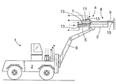
図1は、キャリア2と、削岩機4を可動に取り付けた、少なくとも1つの送りビームと含む削岩掘削装置1を示す。削岩機4は、送り装置5によって、穿孔すべき岩石に向けて押し出し、同様にそれから引き離すことができる。送り装置5は、例えば1つ以上の液圧シリンダで構成して、これらによって削岩機4が適切な伝動部材で動くようにしてもよい。典型的には、送りビーム3は、キャリア2に対して動けるブームに取り付けられる。削岩機4は、この削岩機4へ連結された工具8に対して衝撃パルスを与える衝撃装置7を有している。工具8は、1つ以上のドリルロッド9およびドリルビット10で構成することができる。削岩機4はさらに、工具をその長手軸を中心として回転させる回転装置11含んでよい。穿孔中、衝撃パルスが衝撃装置7によって工具8に対して与えられ、工具は、同時に回転装置11によって回転する。さらに、削岩機4は、穿孔中、岩石に向けて押し出されてドリルビット10が岩石を破壊することができる。削岩は、1つ以上の制御装置12で制御することができる。制御装置12は、コンピュータもしくは同様の装置で構成することができる。穿孔を制御するために、例えば、回転抵抗、衝撃力および送り力を適切なセンサ13で測定することができる。この測定情報をこれらのセンサ13から制御装置12へ送ることができるが、その場合、削岩を制御するための制御方式を設定することができる。さらに、間接測定および計算を用いて、回転抵抗、衝撃力および送り力を判定することもできる。制御装置12は、削岩機4および送り装置5の機能を制御するアクチュエータ、例えば加圧媒体を制御する弁に対して制御指令を出すことができる。削岩機4の衝撃装置7、回転装置11および送り装置5は、加圧媒体作動装置でよく、その場合、測定および制御すべき値は、加圧媒体の圧力でよい。または、これらのアクチュエータは、例えば電気アクチュエータでもよいが、その場合、測定および制御すべき値は電気的値でよい。図1において、測定情報および制御情報の経路を一点鎖線で示す。
FIG. 1 shows a rock drilling rig 1 comprising a
図2は、本発明による制御方式の実施例を示す。図2は3つの曲線がそれぞれ穿孔値を表している。すなわち、第1の曲線(Rot)は回転抵抗を時間の関数として示す。第2の曲線(Feed)は送りを時間の関数として、第3の曲線(Per)は衝撃力を時間の関数として、それぞれ表している。図2はさらに、水平破線(ref)を示すが、これは回転抵抗の基準値を表している。通常の穿孔状態では、回転抵抗(Rot)は基準値(ref)とほぼ一致している。時点t1において、回転抵抗(Rot)はかなり大きくなり始める。したがって、削岩を制御する制御装置12は、所定の制御方式に従って送り(Feed)を減少し始める。この送り(Feed)は、送り力、送り速度、またはその両方を減少することによって、小さくすることができる。さらに、時間限界値txを制御装置12に設定することができ、この時間限界値で決まる時間後に、すなわち、時点t2において、衝撃力(Per)の低減が所定の制御方式に従って始まる。衝撃力(Per)が低減されるのは、回転抵抗(Rot)が時間限界値txで決まる時間内に通常の穿孔状態に相当する基準値(ref)に戻っていない場合のみである。送り(Feed)および衝撃力(Per)は、図2に示すように実質的に線形に減少させることができる。回転抵抗(Rot)が、衝撃力(Per)の減少にもかかわらず所定の時間限界値tyで決まる時間内に基準値(ref)へ戻っていない場合、送りを停止することができ、さらに、必要な場合は、逆進させることができる。したがって、時点t3において、削岩機4の岩石からの引き離しを開始することができる。ドリルビット10はこれによって岩石から離れ、穿孔抵抗は、曲線(Rot)から分かるように、急落する。この問題が解消すると、穿孔は、送りを正常の方向へ向けることによって続けることができ、衝撃力(Per)および送り力もしくは送り速度は、再び徐々に大きくすることができる。時間限界値txおよびtyは、制御装置12において固定的に設定することができ、またはそれぞれの穿孔時間前に場合に応じて設定することができる。場合によっては、3つ以上の限界値を設定することができる。
FIG. 2 shows an embodiment of a control scheme according to the present invention. In FIG. 2, each of the three curves represents a puncture value. That is, the first curve (Rot) shows the rotational resistance as a function of time. The second curve (Feed) represents the feed as a function of time, and the third curve (Per) represents the impact force as a function of time. FIG. 2 further shows a horizontal dashed line (ref), which represents a reference value for the rotational resistance. In a normal drilling state, the rotation resistance (Rot) is almost equal to the reference value (ref). At time t1, the rotational resistance (Rot) starts to increase considerably. Accordingly, the
衝撃力(Per)の減少が時点t2において開始された後、送り(Feed)の減少をまだ続けることができることを記しておく。この減少は、時点t1およびt3間では実質的に均等に続けることができ、またはこの減少は、t1からt2と、t2からt3との間で変化させることができる。送り(Feed)が十分に減少している場合、送り(Feed)を、後に図5に示すように、t1からt3またはこの時間の一部において一定に保つこともできる。 Note that after the impact force (Per) reduction starts at time t2, the feed reduction can still continue. This reduction can continue substantially equally between time points t1 and t3, or this reduction can vary between t1 and t2 and between t2 and t3. If the feed is sufficiently reduced, the feed can also be kept constant from t1 to t3 or part of this time, as shown later in FIG.
したがって、上述の制御方式では、3つの制御動作、すなわち送りの低減、衝撃力の低減、および送りの停止が用いられる。この制御方式はさらに、停止後の送り方向の逆転動作を含んでもよい。さらに、この制御方式の実現には、少なくとも回転抵抗(Rot)の測定またはその他の判定が必要である。これに対して、衝撃力、送り速度および送り力の低減は、衝撃力、送り速度および送り力を測定しないでアルゴリズムによって行なうことができる。 Therefore, in the control method described above, three control operations are used, namely, feed reduction, impact force reduction, and feed stop. This control method may further include a reverse operation of the feed direction after stopping. Furthermore, to realize this control method, at least measurement of rotational resistance (Rot) or other determination is required. In contrast, the impact force, feed speed, and feed force can be reduced by an algorithm without measuring the impact force, feed speed, and feed force.
図3は、本発明による制御方式の第2の実施例を示す。この制御の基本原理および制御動作は、図2におけるものと同じであるが、図3の方式における相違点は少なくとも、第1の時間限界値txだけが制御装置12に設定されていることである。さらに、最小限界値(permin)が衝撃力(Per)に対して設定されている。したがって、回転抵抗(Rot)が衝撃力(Per)の低減にもかかわらず減少せず、さらに衝撃力(Per)がその衝撃力に対して設定されている最小限界値(permin)に達している場合、送り方向が逆転される。衝撃装置が加圧媒体作動装置である場合、限界値(permin)は、例えば衝撃圧力に対する最小限界値にすることができる。図2に比べて更なる他の相違点は、衝撃力(Per)が時間t2からt3の間に非線形に減少することである。衝撃力(Per)の減少は、例えば連続数学関数に一致する。送り(Feed)の減少は、例えば1つ以上の段階で行なうことができる。
FIG. 3 shows a second embodiment of the control method according to the present invention. The basic principle and control operation of this control are the same as those in FIG. 2, but the difference in the method of FIG. 3 is that at least only the first time limit value tx is set in the
図4は、本発明による制御方式の第3の実施例を示し、衝撃力(Per)の減少を開始する時点t2と、送りの停止および方向の逆転を開始する時点t3は、回転抵抗(Rot)に従って調節された時間限界値txおよびtyを用いて判定される。時間限界値txは、例えば回転抵抗(Rot)の増大する程度に従って制御装置12で判定することができる。この増大率を図4では角度係数kで示す。他方、時間限界値txは、回転抵抗(Rot)が回転抵抗の基準値(ref)より大きくなっている時間の長さに従って判定することができる。さらに、時間限界値txを調節する場合、上述の方法の組合せを使用することができる。この場合、増大率ばかりでなく有効時間も調節に考慮することができる。この組合せは、図4では第1の区域A1で示し、その大きさは、制御装置12において数学的手段によって判定することができる。さらに、第2の時間限界値tyは、制御装置12において同様の方法で、すなわち、変化率もしくは時間に基づいて判定することができる。第2の時間限界値tyの調節Cも、上述の態様の組合せに基づいて行なうことができる。この組合せは、図4において第2の区域A2で示す。図4からはさらに、時間帯t2からt3における衝撃力の減少を階段状に行なえることがわかる。
FIG. 4 shows a third embodiment of the control system according to the present invention. The time point t2 at which the impact force (Per) starts to decrease and the time point t3 at which the feed stop and the direction reversal are started ) Using the time limit values tx and ty adjusted according to). The time limit value tx can be determined by the
図5は、本発明による制御方式の第4の実施例を示し、回転抵抗(Rot)に対して最大限界値(rotmax)が設定されている。回転抵抗(Rot)がこの最大限界値(rotmax)を越えた場合、衝撃力(Per)は、本制御方式に従って時点t2において減少する。さらに、制御装置12には、所定の、もしくは可調節の時間限界値tyが設定されている。衝撃力(Per)の減少にもかかわらず回転抵抗(Rot)が、時間限界値tyで決まる時点t3においてまだ基準限界値(ref)より大きい場合、制御装置12は、送りを停止し送り方向を逆転し、このとき、遅くとも回転抵抗(Rot)が減少する。
FIG. 5 shows a fourth embodiment of the control method according to the present invention, in which a maximum limit value (rotmax) is set for the rotation resistance (Rot). When the rotational resistance (Rot) exceeds this maximum limit value (rotmax), the impact force (Per) decreases at time t2 according to this control method. Furthermore, a predetermined or adjustable time limit value ty is set in the
実際上、送りの方向を正常の方向から反対に変更することは、常に送りの停止を伴う。送りの停止後、送りの方向を実質的に直ちに、または所定の遅延の後に逆転することができる。 In practice, changing the feed direction from the normal direction to the opposite always involves stopping the feed. After stopping the feed, the direction of feed can be reversed substantially immediately or after a predetermined delay.
回転抵抗(Rot)は、回転装置11へ流れる加圧媒体の圧力を測定することによって、または回転装置11の流入路と流出路との間の圧力差を測定することによって、判定することができる。さらに、回転抵抗(Rot)は、適切なセンサで工具から直接に測定することもできる。衝撃力(Per)は、用いる衝撃力、流れおよび衝撃周波数に基づいて判定することができ、または工具から直接測定することができる。
The rotational resistance (Rot) can be determined by measuring the pressure of the pressurized medium flowing to the
本発明による方法は、制御装置12に属する1台以上のコンピュータの処理装置にてコンピュータプログラムを走行させることによって実行することができる。本発明の方法を実行するソフトウエア製品を制御装置12の記憶装置に格納することができ、またはこのソフトウエア製品をCD-ROMディスクなどの記憶手段からコンピュータへロードすることができる。さらに、このソフトウエア製品は、他のコンピュータから、例えばデータネットワークを介して採鉱車両の制御装置に属する装置へロードすることができる。
The method according to the present invention can be executed by running a computer program on a processing device of one or more computers belonging to the
送り力、送り速度および衝撃力の調節は、所望の制御方式に従って行なうことができる。送り力、送り速度および衝撃力は、適切な数学的関数に従って階段状、線形または適切な比で減少させることができる。したがって、送りおよび衝撃力の調節は、所望の大きさの1つ以上の調節段階によって行なうことができる。衝撃圧力は、例えば1調節段階で所定の半分の力にまで低減することができる。さらに、衝撃圧力の調節は、送り圧力に対する適切な比で行なうことができる。また、注目すべきことは、考慮の対象は、圧力ではなく、回転抵抗、衝撃および送りを判定することができる電気的値、力、動力または他の測定可能もしくは判定可能な大きさでよいことである。 The feed force, feed speed and impact force can be adjusted according to a desired control method. The feed force, feed rate and impact force can be reduced stepwise, linearly or in a suitable ratio according to a suitable mathematical function. Thus, feed and impact force adjustments can be made by one or more adjustment steps of a desired magnitude. The impact pressure can be reduced, for example, to a predetermined half force in one adjustment step. Further, the impact pressure can be adjusted at an appropriate ratio to the feed pressure. It should also be noted that the subject of consideration is not pressure, but electrical values, forces, power or other measurable or determinable magnitudes that can determine rotational resistance, impact and feed. It is.
さらに注目すべきことは、上述の調節方式のさまざまな組合せおよび改変を穿孔の調節に利用できることである。 It should be further noted that various combinations and modifications of the adjustment schemes described above can be used to adjust the perforations.
添付図面および関連説明は、本発明の概念の説明のみを目的としたものである。本発明の細部は、特許請求の範囲内で改変することができる。 The accompanying drawings and the related description are only intended to illustrate the concept of the invention. The details of the invention may be modified within the scope of the claims.
Claims (23)
前記削岩機の回転装置を制御し、前記工具は、穿孔中、その長手軸を中心に回転し、
前記削岩機を削岩中に削岩すべき岩石に向けて送り出し、また該岩石から送り戻す送り装置を制御し、
削岩中に、少なくとも前記回転装置の回転抵抗を判定して、該回転抵抗が該回転抵抗の所定の基準限界値を越えた時の第1の時点を登録し、
前記送り装置の送りを小さくして前記回転抵抗の所定の基準限界値に向けて該回転抵抗を制御する衝撃式削岩の制御方法において、該方法は、
少なくとも制御の第1の限界値および第2の限界値を判定し、該限界値のうちの少なくとも1つは、2つの連続する制御動作の開始時間の時間差を決定する時間限界値であり、
各限界値に対応する時点において前記回転抵抗を調節する、少なくとも1つの制御動作を行ない、
前記時間限界値に応じて連続制御動作の開始時点間の時間差を設定し、
さらに、前記回転抵抗が第1の限界値に対応する第2の時点において前記回転抵抗の基準限界値より大きいと、前記衝撃装置の衝撃力を小さくし、
前記回転抵抗が第2の限界値に対応する第3の時点において前記回転抵抗の基準限界値より大きいと、前記送りを停止することを特徴とする衝撃式削岩の制御方法。The impact device is controlled in the rock drill that gives impact pulses during drilling to the tool connected to the rock drill,
Controlling the rotation device of the rock drill, the tool rotates about its longitudinal axis during drilling,
Sending the rock drilling machine toward the rock to be rocked during rock drilling, and controlling the feeding device to send back from the rock,
During the rock drilling, at least the rotational resistance of the rotating device is determined, and a first time point when the rotational resistance exceeds a predetermined reference limit value of the rotational resistance is registered,
In the impact-type rock drilling control method of controlling the rotational resistance toward a predetermined reference limit value of the rotational resistance by reducing the feed of the feeder , the method includes:
Determining a first limit value and the second limit value of at least the control, at least one of該限field value is a time limit that determines the time difference between the start times of the two successive control actions,
Performing at least one control action to adjust the rotational resistance at a time corresponding to each limit value;
Set the time difference between the start points of the continuous control operation according to the time limit value,
Further, the rotation resistance is reduced and greater than the reference limit Oite the rotational resistance to the second point in time corresponding to the first limit value, the impact force of the impact device,
Third larger than the reference limit Oite the rotation resistance at the time, the control method for impact drilling, characterized by stopping the feed of the rotation resistance corresponds to a second limit value.
時間限界値を第1の限界値として、また時間限界値を第2の限界値として判定し、
第1の時点から始まる第1の限界値に対応する第2の時点を判定し、
第2の時点から始まる第2の限界値に対応する第3の時点を判定し、
前記送りを、少なくとも第2の時点までは小さくし、
前記回転抵抗が前記基準限界値より大きいと、第2の時点と第3の時点との間に前記衝撃力を減少させ、前記回転抵抗が前記基準限界値より大きいと、第3の時点において前記送りを停止することを特徴とする衝撃式削岩の制御方法。The method of claim 1, wherein the method comprises:
Determine the time limit value as the first limit value and the time limit value as the second limit value,
Determining a second time point corresponding to a first limit value starting from the first time point;
Determining a third time point corresponding to a second limit value starting from the second time point ;
Reducing the feed at least until the second time point;
When the rotational resistance is greater than the reference limit value, the impact force is reduced between a second time point and a third time point, and when the rotational resistance is greater than the reference limit value, A control method for impact-type rock drilling, characterized by stopping feeding.
前記衝撃力に関する最小限界値を判定して、これを第2の限界値として用い、
前記衝撃力が前記最小限界値より小さくなった時点を、第2の限界値に対応する第3の時点として判定することを特徴とする衝撃式削岩の制御方法。The method of claim 1, wherein the method comprises:
Determining a minimum limit value for the impact force and using this as a second limit value;
The impact rock drilling control method characterized in that a point in time when the impact force becomes smaller than the minimum limit value is determined as a third point in time corresponding to the second limit value.
前記回転抵抗に関する最大限界値を判定して、これを第1の限界値として用い、
前記回転抵抗が前記最大限界値より大きくなった時点を、第1の限界値に対応する第2の時点として判定することを特徴とする衝撃式削岩の制御方法。The method of claim 1, wherein the method comprises:
Determining the maximum limit value for the rotational resistance and using this as the first limit value;
The impact rock drilling control method, wherein the time point when the rotational resistance becomes larger than the maximum limit value is determined as a second time point corresponding to the first limit value.
削岩機において、前記削岩機へ連結されている工具に対して削岩中に衝撃パルスを与える衝撃装置と、削岩中に前記工具をその長手軸を中心に回転させる回転装置と、削岩中に前記削岩機を削岩すべき岩石に向けて送り出し、また該岩石から送り戻す送り装置とを制御し、
削岩中に、少なくとも前記回転装置の回転抵抗を判定して、該回転抵抗が該回転抵抗の所定の基準限界値を越えた時の第1の時点を登録し、
前記送り装置の送りを小さくして前記回転抵抗の所定の基準限界値に向けて前記回転抵抗を制御するように構成された衝撃式削岩を制御するソフトウエア製品において、前記制御装置内での該ソフトウエア製品の実行によってさらに、
少なくとも制御の第1の限界値および第2の限界値を判定し、該限界値のうちの少なくとも1つは、2つの連続する制御動作の開始時間の時間差を決定する時間限界値であり、
各限界値に対応する時点において前記回転抵抗を調節する、少なくとも1つの制御動作を行ない、
前記時間限界値に応じて連続制御動作の開始時点間の時間差を設定し、
前記回転抵抗が第1の限界値に対応する第2の時点において前記回転抵抗の基準限界値より大きいと、前記衝撃装置の衝撃力を小さくし、
前記回転抵抗が第2の限界値に対応する第3の時点におい前記回転抵抗の基準限界値より大きいと、前記送りを停止するように構成されていることを特徴とするソフトウエア製品。When the software is executed in the control device that controls rock drilling, at least the following operation, that is, an impact device that gives an impact pulse during drilling to the tool connected to the rock drilling machine in the rock drilling machine A rotary device that rotates the tool about its longitudinal axis during rock drilling, and a feed device that feeds the rock drilling machine toward the rock to be rocked during rock drilling and feeds it back from the rock. ,
During the rock drilling, at least the rotational resistance of the rotating device is determined, and a first time point when the rotational resistance exceeds a predetermined reference limit value of the rotational resistance is registered,
In a software product for controlling impact rock drilling configured to control the rotational resistance toward a predetermined reference limit value of the rotational resistance by reducing the feed of the feeder, in the controller By executing the software product,
Determining a first limit value and the second limit value of at least the control, at least one of該限field value is a time limit that determines the time difference between the start times of the two successive control actions,
Performing at least one control action to adjust the rotational resistance at a time corresponding to each limit value;
Set the time difference between the start points of the continuous control operation according to the time limit value,
When the rotational resistance is greater than the reference limit value of the rotational resistance at the second time point corresponding to the first limit value, the impact force of the impact device is reduced,
A software product configured to stop feeding when the rotational resistance is greater than a reference limit value of the rotational resistance at a third time point corresponding to a second limit value.
少なくとも1つの送りビームと、
該送りビームに可動に配設された、少なくとも1つの削岩機と、
該削岩機を削岩すべき岩石へ向けて送り出し、また該岩石から送り戻す送り装置と含み、
前記削岩機は、該削岩機へ連結された工具に対して衝撃パルスを生成する衝撃装置、および該工具をその長手軸を中心に回転させる回転装置を含み、
少なくとも前記送り装置、衝撃装置および回転装置の機能を制御装置内の制御方式に従って制御する、少なくとも1つの制御装置と、
少なくとも前記回転装置の回転抵抗を判定する手段とを含み、
前記制御装置は、前記回転抵抗が該回転抵抗の所定の基準限界値を超えた時の第1の時点を登録し、
前記送り装置の送りを小さくして前記回転抵抗を該回転抵抗の所定の基準限界値へ向けて制御するように構成された削岩用掘削装置において、
前記制御装置は、少なくとも制御の第1の限界値および第2の限界値を判定し、該限界値のうちの少なくとも1つは、2つの連続する制御動作の開始時間の時間差を決定する時間限界値であり、
各限界値に対応する時点において前記回転抵抗を調節する、少なくとも1つの制御動作を行ない、
前記時間限界値に応じて連続制御動作の開始時点間の時間差を設定し、
前記回転抵抗が第1の限界値に対応する第2の時点において前記回転抵抗の基準限界値より大きいと、前記衝撃装置の衝撃力を小さくし、
前記回転抵抗が第2の限界値に対応する第3の時点において前記回転抵抗の基準限界値より大きいと、前記送りを停止するように構成されていることを特徴とする削岩掘削装置。Career,
At least one feed beam;
At least one rock drill disposed movably on the feed beam;
Including a rocking machine that sends the rock drill toward the rock to be rocked, and a feed device that sends it back from the rock;
The rock drill includes an impact device that generates an impact pulse for a tool connected to the rock drill, and a rotation device that rotates the tool about its longitudinal axis.
At least one control device for controlling at least the functions of the feeding device, the impact device and the rotation device in accordance with a control method in the control device;
Means for determining at least the rotational resistance of the rotating device ,
The control device registers a first time point when the rotational resistance exceeds a predetermined reference limit value of the rotational resistance,
In the drilling device for rock drilling configured to control the rotation resistance toward a predetermined reference limit value of the rotation resistance by reducing the feed of the feeding device,
Wherein the controller determines the first limit value and the second limit value of at least the control, at least one of該限field value, the time limit that determines the time difference between the start times of the two successive control actions Value,
Performing at least one control action to adjust the rotational resistance at a time corresponding to each limit value;
Set the time difference between the start points of the continuous control operation according to the time limit value,
When the rotational resistance is greater than the reference limit value of the rotational resistance at the second time point corresponding to the first limit value, the impact force of the impact device is reduced,
The rock drilling excavator is configured to stop the feed when the rotation resistance is larger than a reference limit value of the rotation resistance at a third time point corresponding to a second limit value.
少なくとも1つの送りビームと、
該送りビームに可動に配設された、少なくとも1つの削岩機と、
前記削岩機を削岩すべき岩石へ向けて送り出し、また該岩石から送り戻す送り装置と含み、
前記削岩機は、該削岩機へ連結された工具に対して衝撃パルスを生成する衝撃装置および該工具をその長手軸を中心に回転させる回転装置を含み、
少なくとも前記送り装置、衝撃装置および回転装置の機能を制御装置内の制御方式に従って制御する、少なくとも1つの制御装置と、
少なくとも前記回転装置の回転抵抗を判定する手段とを含み、
前記制御装置は、前記回転抵抗が該回転抵抗の所定の基準限界値を超えた時の第1の時点を登録し、
前記送り装置の送りを小さくして前記回転抵抗を該回転抵抗の所定の基準限界値へ向けて制御するように構成された削岩用掘削装置において、
前記制御装置は、制御するために、第1の時点からモニタする、少なくとも1つの時間限界値を判定するように構成され、
前記制御装置は、前記回転抵抗が前記時間限界値の時間内に基準限界値に戻っていない場合に、前記時間限界値に対応する第2の時点において前記回転抵抗を調節する、少なくとも1つの制御動作を行なうように構成されていることを特徴とする削岩掘削機。Career,
At least one feed beam;
At least one rock drill disposed movably on the feed beam;
Sending the rock drill toward the rock to be rocked, and a feeding device for sending back from the rock;
The rock drill includes an impact device that generates an impact pulse with respect to a tool connected to the rock drill, and a rotating device that rotates the tool around its longitudinal axis.
At least one control device for controlling at least the functions of the feeding device, the impact device and the rotation device in accordance with a control method in the control device;
Means for determining at least the rotational resistance of the rotating device ,
The control device registers a first time point when the rotational resistance exceeds a predetermined reference limit value of the rotational resistance,
In the drilling device for rock drilling configured to control the rotation resistance toward a predetermined reference limit value of the rotation resistance by reducing the feed of the feeding device,
The controller is configured to determine at least one time limit value to monitor from a first time point for control;
Wherein the control device, when the rotation resistance has not returned to the reference limit value in time of the time limit value, to adjust the Oite the rotational resistance to the second point in time corresponding to the time limit, at least 1 A rock drilling excavator characterized in that it is configured to perform two control operations.
Applications Claiming Priority (2)
| Application Number | Priority Date | Filing Date | Title |
|---|---|---|---|
| FI20045352A FI121027B (en) | 2004-09-24 | 2004-09-24 | Procedure for controlling striking rock drilling, software product and rock drilling device |
| PCT/FI2005/050325 WO2006032733A1 (en) | 2004-09-24 | 2005-09-22 | Arrangement for controlling percussive rock drilling |
Publications (2)
| Publication Number | Publication Date |
|---|---|
| JP2008514831A JP2008514831A (en) | 2008-05-08 |
| JP4660551B2 true JP4660551B2 (en) | 2011-03-30 |
Family
ID=33041630
Family Applications (1)
| Application Number | Title | Priority Date | Filing Date |
|---|---|---|---|
| JP2007532915A Expired - Fee Related JP4660551B2 (en) | 2004-09-24 | 2005-09-22 | Control method of impact rock drilling |
Country Status (12)
| Country | Link |
|---|---|
| US (1) | US7604070B2 (en) |
| EP (1) | EP1792051B1 (en) |
| JP (1) | JP4660551B2 (en) |
| CN (1) | CN101027455B (en) |
| AT (1) | ATE475777T1 (en) |
| AU (1) | AU2005286447B2 (en) |
| CA (1) | CA2581324C (en) |
| DE (1) | DE602005022597D1 (en) |
| FI (1) | FI121027B (en) |
| NO (1) | NO20072088L (en) |
| WO (1) | WO2006032733A1 (en) |
| ZA (1) | ZA200702414B (en) |
Families Citing this family (13)
| Publication number | Priority date | Publication date | Assignee | Title |
|---|---|---|---|---|
| FI116968B (en) * | 2004-07-02 | 2006-04-28 | Sandvik Tamrock Oy | Procedure for control of impactor, program product and impactor |
| US7921936B2 (en) * | 2005-02-25 | 2011-04-12 | Commonwealth Scientific And Industrial Research Organisation | Method and system for controlling an excavating apparatus |
| SE530984C2 (en) * | 2007-03-16 | 2008-11-11 | Atlas Copco Rock Drills Ab | Method and apparatus for controlling a rock drill, as well as rock drill and rock drill rig |
| SE533986C2 (en) | 2008-10-10 | 2011-03-22 | Atlas Copco Rock Drills Ab | Method device and drilling rig and computerized control system for controlling a rock drill when drilling in rock |
| WO2010149827A1 (en) * | 2009-06-26 | 2010-12-29 | Sandvik Mining And Construction Oy | Method for controlling rock drilling |
| US8261855B2 (en) | 2009-11-11 | 2012-09-11 | Flanders Electric, Ltd. | Methods and systems for drilling boreholes |
| CN102352751B (en) * | 2011-10-10 | 2014-12-31 | 攀钢集团工程技术有限公司 | Ashlar lifting machine |
| EP3310988A1 (en) * | 2015-06-17 | 2018-04-25 | Sandvik Mining and Construction Oy | Arrangement for controlling collaring drilling |
| AU2016332745C1 (en) | 2015-09-30 | 2021-07-01 | Jaron Lyell Mcmillan | Percussion device |
| CN105373099B (en) * | 2015-11-27 | 2018-05-25 | 北京航空航天大学 | A kind of drilling tool technological procedure parameter regulation experimental rig controller and control method |
| US11448013B2 (en) | 2018-12-05 | 2022-09-20 | Epiroc Drilling Solutions, Llc | Method and apparatus for percussion drilling |
| PL3901409T3 (en) * | 2020-04-22 | 2024-05-06 | Sandvik Mining And Construction Tools Ab | Smart rock bolt driver |
| WO2022115016A1 (en) | 2020-11-27 | 2022-06-02 | Epiroc Rock Drills Aktiebolag | Arrangement of controlling drilling parameters during extraction of a drill string |
Citations (1)
| Publication number | Priority date | Publication date | Assignee | Title |
|---|---|---|---|---|
| JP2005505711A (en) * | 2001-10-18 | 2005-02-24 | サンドビク タムロック オサケ ユキチュア | Control method and equipment for impact rock drilling with stress level determined from measured feed rate |
Family Cites Families (27)
| Publication number | Priority date | Publication date | Assignee | Title |
|---|---|---|---|---|
| US3561542A (en) * | 1969-03-20 | 1971-02-09 | Gardner Denver Co | Control system for rock drills |
| FI55892C (en) | 1974-03-18 | 1979-10-10 | Tampella Oy Ab | HYDRAULISK BORRMASKIN I SYNNERHET BERGBORRNINGSMASKIN |
| JPS52117201A (en) * | 1976-03-29 | 1977-10-01 | Furukawa Kogyo Kk | Device for automatically controlling rotary boring machine |
| US4246973A (en) * | 1978-01-23 | 1981-01-27 | Cooper Industries, Inc. | Controls for hydraulic percussion drill |
| US4165789A (en) * | 1978-06-29 | 1979-08-28 | United States Steel Corporation | Drilling optimization searching and control apparatus |
| US4440236A (en) * | 1979-09-20 | 1984-04-03 | Toyo Kogyo Co. Ltd. | Hydraulic control system for a rock drill |
| JPS5655684A (en) * | 1979-10-06 | 1981-05-16 | Toyo Kogyo Co | Feed controller circuit for hydraulic rock driller |
| US4449592A (en) * | 1981-03-23 | 1984-05-22 | Cooper Industries, Inc. | Automatic drill string section changer |
| AT381363B (en) | 1983-11-08 | 1986-10-10 | Ver Edelstahlwerke Ag | DEVICE FOR IMPACTING DRILLING |
| JPH0631522B2 (en) * | 1985-12-27 | 1994-04-27 | 古河機械金属株式会社 | Drilling machine controller |
| FR2629844B1 (en) * | 1988-04-06 | 1991-09-27 | Clextral | PROCESS FOR THE MANUFACTURE OF A PAPER PULP FOR TRUST USE |
| DE4028595A1 (en) * | 1990-09-08 | 1992-03-12 | Krupp Maschinentechnik | HYDRAULICALLY OPERATED PERFORMANCE |
| FI88744C (en) * | 1991-04-25 | 1993-06-28 | Tamrock Oy | For the purposes of this Regulation |
| FI94663C (en) * | 1994-02-28 | 1995-10-10 | Tamrock | Device in a rock drilling control system |
| JPH09119282A (en) * | 1995-10-26 | 1997-05-06 | Furukawa Co Ltd | Monitor for drilling machine |
| AU711214B2 (en) * | 1996-06-25 | 1999-10-07 | Tamrock Oy | Method and arrangement for controlling rock drilling |
| FI105943B (en) * | 1996-06-25 | 2000-10-31 | Tamrock Oy | Procedure and arrangement for controlling the drilling of the rock drill |
| FI108564B (en) | 1996-12-12 | 2002-02-15 | Tamrock Oy | Process and arrangement for controlling rock drilling |
| FI105054B (en) | 1997-06-13 | 2000-05-31 | Tamrock Oy | Method for controlling rock drilling |
| JP3488905B2 (en) * | 1997-12-09 | 2004-01-19 | ヤマモトロックマシン株式会社 | Hydraulic rock drill controller |
| JP3488906B2 (en) * | 1997-12-16 | 2004-01-19 | ヤマモトロックマシン株式会社 | Hydraulic rock drill controller |
| US6637522B2 (en) * | 1998-11-24 | 2003-10-28 | J. H. Fletcher & Co., Inc. | Enhanced computer control of in-situ drilling system |
| SE515204C2 (en) * | 1999-11-03 | 2001-06-25 | Atlas Copco Rock Drills Ab | Method and apparatus for controlling a rock drill |
| US6293359B1 (en) * | 2000-06-05 | 2001-09-25 | Cubex Limited | Pressure control of a drilling apparatus |
| FI115553B (en) * | 2001-05-15 | 2005-05-31 | Sandvik Tamrock Oy | Arrangement for drilling control |
| FI118306B (en) | 2001-12-07 | 2007-09-28 | Sandvik Tamrock Oy | Methods and devices for controlling the operation of a rock drilling device |
| FI112525B (en) * | 2002-02-22 | 2003-12-15 | Sandvik Tamrock Oy | Arrangement for control of striking rock drilling |
-
2004
- 2004-09-24 FI FI20045352A patent/FI121027B/en not_active IP Right Cessation
-
2005
- 2005-09-22 AT AT05789980T patent/ATE475777T1/en not_active IP Right Cessation
- 2005-09-22 JP JP2007532915A patent/JP4660551B2/en not_active Expired - Fee Related
- 2005-09-22 CN CN2005800324832A patent/CN101027455B/en not_active Expired - Fee Related
- 2005-09-22 CA CA002581324A patent/CA2581324C/en not_active Expired - Fee Related
- 2005-09-22 AU AU2005286447A patent/AU2005286447B2/en not_active Ceased
- 2005-09-22 WO PCT/FI2005/050325 patent/WO2006032733A1/en active Application Filing
- 2005-09-22 DE DE602005022597T patent/DE602005022597D1/en active Active
- 2005-09-22 US US11/663,590 patent/US7604070B2/en not_active Expired - Fee Related
- 2005-09-22 EP EP05789980A patent/EP1792051B1/en not_active Not-in-force
-
2007
- 2007-03-23 ZA ZA200702414A patent/ZA200702414B/en unknown
- 2007-04-23 NO NO20072088A patent/NO20072088L/en not_active Application Discontinuation
Patent Citations (1)
| Publication number | Priority date | Publication date | Assignee | Title |
|---|---|---|---|---|
| JP2005505711A (en) * | 2001-10-18 | 2005-02-24 | サンドビク タムロック オサケ ユキチュア | Control method and equipment for impact rock drilling with stress level determined from measured feed rate |
Also Published As
| Publication number | Publication date |
|---|---|
| ATE475777T1 (en) | 2010-08-15 |
| AU2005286447A1 (en) | 2006-03-30 |
| ZA200702414B (en) | 2008-07-30 |
| FI121027B (en) | 2010-06-15 |
| CN101027455B (en) | 2010-06-16 |
| NO20072088L (en) | 2007-04-23 |
| FI20045352A (en) | 2006-03-25 |
| US7604070B2 (en) | 2009-10-20 |
| US20080087467A1 (en) | 2008-04-17 |
| WO2006032733A1 (en) | 2006-03-30 |
| FI20045352A0 (en) | 2004-09-24 |
| CA2581324C (en) | 2009-12-01 |
| CA2581324A1 (en) | 2006-03-30 |
| AU2005286447B2 (en) | 2010-02-25 |
| EP1792051A4 (en) | 2008-06-18 |
| EP1792051B1 (en) | 2010-07-28 |
| EP1792051A1 (en) | 2007-06-06 |
| JP2008514831A (en) | 2008-05-08 |
| CN101027455A (en) | 2007-08-29 |
| DE602005022597D1 (en) | 2010-09-09 |
Similar Documents
| Publication | Publication Date | Title |
|---|---|---|
| JP4660551B2 (en) | Control method of impact rock drilling | |
| CA3025185C (en) | System and method for controlling a drilling machine | |
| US8136612B2 (en) | Constant-mode auto-drill with pressure derivative control | |
| EP2140105B1 (en) | Method and device for controlling at least one drilling parameter for rock drilling. | |
| AU2003276295B2 (en) | Arrangement for controlling rock drilling | |
| US9033065B2 (en) | Method and apparatus for controlling rock drilling | |
| JP2008523279A (en) | Drilling parameter control apparatus and method | |
| SE526462C2 (en) | Procedure, program and arrangement for the control of slag drilling | |
| JP5393490B2 (en) | Rock drill control method and apparatus and rock drill | |
| EP2140107A1 (en) | Method and device for controlling at least one drilling parameter for rock drilling | |
| WO2021065455A1 (en) | Valve system, work machine, valve control method, program, and recording medium | |
| CN117430045A (en) | Engineering machinery power system and control unit thereof |
Legal Events
| Date | Code | Title | Description |
|---|---|---|---|
| A977 | Report on retrieval |
Free format text: JAPANESE INTERMEDIATE CODE: A971007 Effective date: 20090306 |
|
| A131 | Notification of reasons for refusal |
Free format text: JAPANESE INTERMEDIATE CODE: A131 Effective date: 20100525 |
|
| A521 | Request for written amendment filed |
Free format text: JAPANESE INTERMEDIATE CODE: A523 Effective date: 20100818 |
|
| TRDD | Decision of grant or rejection written | ||
| A01 | Written decision to grant a patent or to grant a registration (utility model) |
Free format text: JAPANESE INTERMEDIATE CODE: A01 Effective date: 20101130 |
|
| A01 | Written decision to grant a patent or to grant a registration (utility model) |
Free format text: JAPANESE INTERMEDIATE CODE: A01 |
|
| A61 | First payment of annual fees (during grant procedure) |
Free format text: JAPANESE INTERMEDIATE CODE: A61 Effective date: 20101228 |
|
| FPAY | Renewal fee payment (event date is renewal date of database) |
Free format text: PAYMENT UNTIL: 20140107 Year of fee payment: 3 |
|
| R150 | Certificate of patent or registration of utility model |
Free format text: JAPANESE INTERMEDIATE CODE: R150 |
|
| R250 | Receipt of annual fees |
Free format text: JAPANESE INTERMEDIATE CODE: R250 |
|
| LAPS | Cancellation because of no payment of annual fees |