JP4657148B2 - Charge control device - Google Patents
Charge control device Download PDFInfo
- Publication number
- JP4657148B2 JP4657148B2 JP2006144051A JP2006144051A JP4657148B2 JP 4657148 B2 JP4657148 B2 JP 4657148B2 JP 2006144051 A JP2006144051 A JP 2006144051A JP 2006144051 A JP2006144051 A JP 2006144051A JP 4657148 B2 JP4657148 B2 JP 4657148B2
- Authority
- JP
- Japan
- Prior art keywords
- charging
- stage
- battery
- voltage
- time
- Prior art date
- Legal status (The legal status is an assumption and is not a legal conclusion. Google has not performed a legal analysis and makes no representation as to the accuracy of the status listed.)
- Expired - Fee Related
Links
Images


Classifications
-
- H—ELECTRICITY
- H02—GENERATION; CONVERSION OR DISTRIBUTION OF ELECTRIC POWER
- H02J—CIRCUIT ARRANGEMENTS OR SYSTEMS FOR SUPPLYING OR DISTRIBUTING ELECTRIC POWER; SYSTEMS FOR STORING ELECTRIC ENERGY
- H02J7/00—Circuit arrangements for charging or depolarising batteries or for supplying loads from batteries
- H02J7/007—Regulation of charging or discharging current or voltage
- H02J7/0071—Regulation of charging or discharging current or voltage with a programmable schedule
-
- G—PHYSICS
- G01—MEASURING; TESTING
- G01R—MEASURING ELECTRIC VARIABLES; MEASURING MAGNETIC VARIABLES
- G01R31/00—Arrangements for testing electric properties; Arrangements for locating electric faults; Arrangements for electrical testing characterised by what is being tested not provided for elsewhere
- G01R31/36—Arrangements for testing, measuring or monitoring the electrical condition of accumulators or electric batteries, e.g. capacity or state of charge [SoC]
- G01R31/382—Arrangements for monitoring battery or accumulator variables, e.g. SoC
-
- H—ELECTRICITY
- H02—GENERATION; CONVERSION OR DISTRIBUTION OF ELECTRIC POWER
- H02J—CIRCUIT ARRANGEMENTS OR SYSTEMS FOR SUPPLYING OR DISTRIBUTING ELECTRIC POWER; SYSTEMS FOR STORING ELECTRIC ENERGY
- H02J7/00—Circuit arrangements for charging or depolarising batteries or for supplying loads from batteries
- H02J7/0047—Circuit arrangements for charging or depolarising batteries or for supplying loads from batteries with monitoring or indicating devices or circuits
-
- H—ELECTRICITY
- H02—GENERATION; CONVERSION OR DISTRIBUTION OF ELECTRIC POWER
- H02J—CIRCUIT ARRANGEMENTS OR SYSTEMS FOR SUPPLYING OR DISTRIBUTING ELECTRIC POWER; SYSTEMS FOR STORING ELECTRIC ENERGY
- H02J7/00—Circuit arrangements for charging or depolarising batteries or for supplying loads from batteries
- H02J7/007—Regulation of charging or discharging current or voltage
- H02J7/00712—Regulation of charging or discharging current or voltage the cycle being controlled or terminated in response to electric parameters
-
- H—ELECTRICITY
- H02—GENERATION; CONVERSION OR DISTRIBUTION OF ELECTRIC POWER
- H02J—CIRCUIT ARRANGEMENTS OR SYSTEMS FOR SUPPLYING OR DISTRIBUTING ELECTRIC POWER; SYSTEMS FOR STORING ELECTRIC ENERGY
- H02J7/00—Circuit arrangements for charging or depolarising batteries or for supplying loads from batteries
- H02J7/007—Regulation of charging or discharging current or voltage
- H02J7/007188—Regulation of charging or discharging current or voltage the charge cycle being controlled or terminated in response to non-electric parameters
- H02J7/007192—Regulation of charging or discharging current or voltage the charge cycle being controlled or terminated in response to non-electric parameters in response to temperature
- H02J7/007194—Regulation of charging or discharging current or voltage the charge cycle being controlled or terminated in response to non-electric parameters in response to temperature of the battery
Landscapes
- Engineering & Computer Science (AREA)
- Power Engineering (AREA)
- Physics & Mathematics (AREA)
- General Physics & Mathematics (AREA)
- Charge And Discharge Circuits For Batteries Or The Like (AREA)
- Secondary Cells (AREA)
- Electric Propulsion And Braking For Vehicles (AREA)
Description
本発明は、サイクル用途に用いられる蓄電池の充電制御装置に関する。 The present invention relates to a storage battery charge control device used for cycle applications.
従来から、電動自動車等で使用される鉛蓄電池を充電制御する技術として、特許文献1の充電方法が知られている。この特許文献1のものでは、定電流多段充電方式を採用し、1回の充電動作に対して複数段の充電ステップ(充電ステージ)を順番に行うようにしている。鉛電池に充電する充電電流値は、各充電ステップごとに決められており、充電ステップが後段に進むほど低い値に設定される。各充電ステップにおいては、その定められた充電電流値に基づいて蓄電池を充電し電池電圧が所定電圧Vrに達すると次段の充電ステップに移行する。
この場合、初回の充電ステップにおいては、その充電ステップにおける充電電気量と電池温度とから、最終段ステップの充電時間を決定するようにしている。そして、最終段ステップにおいては、この充電時間が経過したときに充電完了する。
In this case, in the first charging step, the charging time of the final stage step is determined from the amount of charge in the charging step and the battery temperature. In the final step, charging is completed when this charging time has elapsed.
しかしながら、上述した充電方法を採用した場合には、蓄電池の劣化状態によっては、いつまでたっても次段の充電ステップに移行できないケースが生じてしまう。つまり、電池電圧が所定電圧Vrに達したときに次段の充電ステップへ移行するように条件設定しているため、特に、充電電流値を低くして充電する後段の充電ステップにおいては、蓄電池が劣化していると電池電圧がステップ移行判定条件である所定電圧Vrに達しにくい。この結果、過充電となってしまい、蓄電池の寿命を短くしてしまう。 However, when the above-described charging method is adopted, depending on the deterioration state of the storage battery, there may be a case in which it is not possible to move to the next charging step. That is, since the condition is set so that when the battery voltage reaches the predetermined voltage Vr, the process proceeds to the next charging step. In particular, in the subsequent charging step in which charging is performed with a lower charging current value, the storage battery is If it is deteriorated, it is difficult for the battery voltage to reach the predetermined voltage Vr, which is the step transition determination condition. As a result, the battery is overcharged and the life of the storage battery is shortened.
本発明は、上記課題に対処するためになされたもので、蓄電池の充電過不足を良好に抑制する充電制御装置を提供することを目的とする。 The present invention has been made to address the above-described problems, and an object of the present invention is to provide a charge control device that satisfactorily suppresses overcharge and shortage of a storage battery.
上記目的を達成するために、本発明の構成上の特徴は、蓄電池を充電する充電器を備え、初回充電ステージから最終充電ステージまでの複数回の充電ステージを、各充電ステージの充電電流値を直前の充電ステージの電流値以下に設定して順番に行なう充電制御装置において、蓄電池の電圧を検出する電池電圧検出手段と、蓄電池の温度を検出する電池温度検出手段と、上記電池温度検出手段により検出される電池温度に応じて充電ステージの上限時間を設定する上限時間設定手段と、上記電池電圧検出手段により検出される電池電圧が所定の切替電圧に達したか否かを判定する電圧判定手段と、上記充電ステージの充電開始から計時し、上記上限時間設定手段により設定される充電ステージの上限時間に達したか否かを判定するタイムアップ判定手段と、最終充電ステージの少なくとも1回前の充電ステージから最終充電ステージまでの移行を、上記電圧判定手段により電池電圧が上記切替電圧に達したと判定された電圧判定出力、あるいは、上記タイムアップ判定手段により上記上限時間に達したと判定された時間判定出力の何れか一方を受けたときに行うステージ切替制御手段と、上記最終充電ステージを充電時間の短いノーマルモードと充電時間の長いロングモードとに切り替える充電モード切替手段と、上記初回充電ステージから最終充電ステージまでの充電動作を1回の充電動作として充電動作回数をカウントする充電回数カウント手段と、予め設定された所定充電回数おきに上記ロングモードを選択し、それ以外はノーマルモードを選択して、選択した充電モードを上記充電モード切替手段に指令する充電モード選択手段とを備えたことにある。 In order to achieve the above object, the constitutional feature of the present invention includes a charger for charging a storage battery, and a plurality of charging stages from the initial charging stage to the final charging stage, and the charging current value of each charging stage. In a charging control device that is set in order to be equal to or less than the current value of the immediately preceding charging stage, battery voltage detecting means for detecting the voltage of the storage battery, battery temperature detecting means for detecting the temperature of the storage battery, and the battery temperature detecting means Upper limit time setting means for setting the upper limit time of the charging stage according to the detected battery temperature, and voltage determination means for determining whether or not the battery voltage detected by the battery voltage detection means has reached a predetermined switching voltage And a time-up to determine whether or not the charging stage upper limit time set by the upper limit time setting means has been reached. A transition from the charging stage to the final charging stage at least once before the final charging stage, a voltage determination output determined by the voltage determining means that the battery voltage has reached the switching voltage, or the time The stage switching control means that is performed when any one of the time determination outputs determined to have reached the upper limit time by the up determination means, the normal mode with a short charging time and the long charging time with the final charging stage Charging mode switching means for switching to the mode, charging number counting means for counting the number of charging operations as a single charging operation from the first charging stage to the final charging stage, and at predetermined preset charging times Select the long mode above, otherwise select the normal mode and select the selected charging mode. In that a charging mode selecting means for commanding the serial charge mode switching means.
この発明によれば、上限時間設定手段により最終充電ステージの少なくとも1回前の充電ステージにおける上限時間を電池温度に応じて設定し、最終充電ステージの少なくとも1回前の充電ステージにおける充電中には、電圧判定手段により電池電圧が切替電圧に達したか否かを判定するとともに、タイムアップ判定手段によりその充電ステージの充電開始からの経過時間が上限時間に達したか否かを判定する。そして、電圧判定手段あるいはタイムアップ判定手段の何れか一方から判定出力がなされたとき、つまり、電池電圧が切替電圧に到達したとき、あるいは充電時間が上限時間に到達したときに、ステージ切替制御手段は、充電ステージを最終充電ステージに移行させる。また、充電回数カウント手段が蓄電池の充電動作回数をカウントし、そのカウント値に基づいて充電モード選択手段が所定充電回数おきにロングモードを選択する。充電モード切替手段は、ロングモードが選択された場合には、充電モードをロングモードに切り替えて最終充電ステージを通常よりも長い時間に設定する。 According to this invention, the upper limit time setting means sets the upper limit time in the charging stage at least once before the final charging stage according to the battery temperature, and during charging in the charging stage at least once before the final charging stage. The voltage determination means determines whether or not the battery voltage has reached the switching voltage, and the time-up determination means determines whether or not the elapsed time from the start of charging of the charging stage has reached the upper limit time. Then, when a determination output is made from either the voltage determination means or the time-up determination means, that is, when the battery voltage reaches the switching voltage, or when the charging time reaches the upper limit time, the stage switching control means Shifts the charging stage to the final charging stage. Further, the charging number counting means counts the number of times the storage battery is charged, and the charging mode selection means selects the long mode every predetermined number of charging times based on the count value. When the long mode is selected, the charging mode switching unit switches the charging mode to the long mode and sets the final charging stage to a longer time than usual.
従って、蓄電池が劣化して電池電圧の上昇があまり得られない場合でも最終充電ステージに移行させることができ、しかも、上限時間が電池温度に応じて設定されるため、最適な上限時間を設定することができる。つまり、充電効率の良い高温時に比べて、充電効率の悪い低温時の上限時間を長く設定することができる。この結果、電池温度によって充電率が大きく変化してしまうといった不具合を低減し、蓄電池の充電過不足を抑制することができる。また、定期的に最終充電ステージでの充電時間を長めに設定することで、蓄電池の完全充電を図って充電不足を補うことができる。この場合、1回だけのロングモード充電をみれば過充電が懸念されるが、ロングモード充電を行う周期を適宜設定することで、平均的にみた過充電を防止して電池寿命の低下を防止することができる。 Therefore, even when the storage battery is deteriorated and the battery voltage cannot be increased so much, it is possible to shift to the final charging stage, and the upper limit time is set according to the battery temperature, so an optimal upper limit time is set. be able to. That is, the upper limit time at low temperatures with poor charging efficiency can be set longer than at high temperatures with good charging efficiency. As a result, it is possible to reduce a problem that the charging rate greatly changes depending on the battery temperature, and to suppress overcharging and undercharging of the storage battery. In addition, by setting the charging time at the final charging stage longer, it is possible to fully charge the storage battery to compensate for insufficient charging. In this case, overcharge may be a concern if only one long mode charge is seen, but by setting the cycle for long mode charge as appropriate, it prevents overcharge on average and prevents a decrease in battery life. can do.
尚、上限時間設定手段は、全ての充電ステージの上限時間を設定する必要はなく、最終充電ステージの少なくとも1回前の充電ステージにおける上限時間を設定すればよい。また、タイムアップ判定手段も、全ての充電ステージにおける充電時間判定をする必要はなく、最終充電ステージの少なくとも1回前の充電ステージにおける時間判定を行えばよい。
従って、初回充電ステージから最終充電ステージのn回前(n>1となる自然数)までの充電ステージに関しては、例えば、電圧判定手段の電圧判定出力のみに基づいて、あるいは、この電圧判定出力と予め設定した上限時間の時間判定出力とに基づいて次の充電ステージに移行するように切り替える手段を設けても良い。
Note that the upper limit time setting means need not set the upper limit times for all the charging stages, but may set the upper limit times for the charging stage at least once before the final charging stage. In addition, the time-up determination unit does not need to determine the charging time in all the charging stages, and may perform the time determination in the charging stage at least once before the final charging stage.
Therefore, with respect to the charging stage from the initial charging stage to n times before the final charging stage (a natural number satisfying n> 1), for example, based on only the voltage determination output of the voltage determination means, or in advance with this voltage determination output. Means for switching to shift to the next charging stage based on the time determination output of the set upper limit time may be provided.
また、最終充電ステージについては、任意に充電終了タイミングを設定すればよいが、例えば、初回充電ステージにおける充電電気量と電池温度とに基づいて充電時間を設定する手段を設けても良い。 For the final charging stage, the charging end timing may be arbitrarily set. For example, a means for setting the charging time based on the amount of charged electricity and the battery temperature in the initial charging stage may be provided.
本発明の他の特徴は、上記電圧判定手段により電池電圧が上記切替電圧に達したと判定される前に上記タイムアップ判定手段により上記上限時間に達したと判定されて上記最終充電ステージに移行した場合と、上記タイムアップ判定手段により上記上限時間に達したと判定される前に上記電圧判定手段により電池電圧が上記切替電圧に達したと判定されて上記最終充電ステージに移行した場合とで、上記ロングモードを選択するサイクルを異なる値に設定するモードサイクル変更手段を備えたことにある。 Another feature of the present invention is that, before the voltage determining means determines that the battery voltage has reached the switching voltage, the time-up determining means determines that the upper limit time has been reached and shifts to the final charging stage. And when the battery voltage has reached the switching voltage by the voltage determination means before the time-up determination means determines that the upper limit time has been reached, and the process proceeds to the final charging stage. The mode cycle changing means for setting the cycle for selecting the long mode to a different value is provided.
この場合、上記モードサイクル変更手段は、上記タイムアップ判定手段により上記上限時間に達したと判定される前に上記電圧判定手段により電池電圧が上記切替電圧に達したと判定されて上記最終充電ステージに移行した場合に比べて、上記電圧判定手段により電池電圧が上記切替電圧に達したと判定される前に上記タイムアップ判定手段により上記上限時間に達したと判定されて上記最終充電ステージに移行した場合は、上記ロングモードを選択するサイクルを長く設定するとよい。 In this case, the mode cycle changing means determines that the battery voltage has reached the switching voltage by the voltage determining means before the time-up determining means determines that the upper limit time has been reached, and the final charge stage. Compared to the case where the battery voltage has shifted to, the time determination unit determines that the upper limit time has been reached before the voltage determination unit determines that the battery voltage has reached the switching voltage, and shifts to the final charge stage. In this case, it is preferable to set a long cycle for selecting the long mode.
この発明によれば、最終充電ステージに移行したときのステージ移行成立条件に応じて、ロングモード充電を選択するサイクル、つまり所定充電回数ごとに行うロングモード充電の周期が変更される。
蓄電池の劣化度合いが高い場合には、電池電圧が切替電圧に到達することなく充電時間が上限時間に達するケースがある。こうしたケースでは、蓄電池の充電時間が長いため充電率が高くなっている。
そこで、こうした蓄電池が劣化している状況においては、ロングモード充電を行う頻度を少なくすることで平均的な充電率を適正範囲に維持して、過充電による蓄電池の劣化を抑制する。
According to the present invention, the cycle for selecting the long mode charging, that is, the cycle of the long mode charging performed every predetermined number of times of charging, is changed according to the stage transition establishment condition when shifting to the final charging stage.
When the degree of deterioration of the storage battery is high, there is a case where the charging time reaches the upper limit time without the battery voltage reaching the switching voltage. In such a case, the charging rate is high because the charging time of the storage battery is long.
Therefore, in such a situation where the storage battery is deteriorated, the average charging rate is maintained in an appropriate range by reducing the frequency of performing the long mode charging, and the deterioration of the storage battery due to overcharging is suppressed.
本発明の他の特徴は、上記ステージ切替制御手段は、最終充電ステージのn回前(n>1となる自然数)の充電ステージから最終充電ステージまでの間の各充電ステージにおける次の充電ステージへの移行を、上記電圧判定手段により電池電圧が上記切替電圧に達したと判定された電圧判定出力、あるいは、上記タイムアップ判定手段により上記上限時間に達したと判定された時間判定出力の何れか一方を受けたときに行い、上記モードサイクル変更手段は、上記電圧判定手段により電池電圧が上記切替電圧に達したと判定される前に上記タイムアップ判定手段により上記上限時間に達したと判定されて次の充電ステージに移行した場合、上記上限時間の到達判定がなされた充電ステージが早い段階であるほど上記ロングモードを選択するサイクルを長く設定することにある。 Another feature of the present invention is that the stage switching control means moves to the next charging stage in each charging stage between the charging stage n times before the final charging stage (natural number satisfying n> 1) and the final charging stage. The voltage determination output determined by the voltage determination means that the battery voltage has reached the switching voltage, or the time determination output determined by the time-up determination means that the upper limit time has been reached. The mode cycle changing means determines that the upper limit time has been reached by the time-up determining means before the voltage determining means determines that the battery voltage has reached the switching voltage. If the charging stage is shifted to the next charging stage, the longer the charging stage for which the determination of arrival of the upper limit time is made, the earlier the charging stage is selected. It is to set a longer cycle.
この発明によれば、最終充電ステージのn回前から各充電ステージにおける次ステージへの移行を、ステージ切替制御手段により電池電圧が切替電圧に到達したとき、あるいは充電時間が上限時間に到達したときに行う。定電流多段充電を行う場合、初期の充電ステージほど大きな充電電流値が設定されるため本来なら電池電圧の上昇が得られやすいが、電池電圧の劣化度合いが大きいと、初期の充電ステージにおいても適切な電池電圧上昇が得られなくなることがある。この場合、その充電ステージが早い段階であるほど(n段階の値nが小さいほど)後段での充電ステージも含めた充電時間が長くなり、充電率が高くなる。
そこで、この発明では、電池電圧が切替電圧に到達することなく充電時間が上限時間に達して次の充電ステージに移行した場合には、その充電ステージが早い段階であるほどロングモードを選択するサイクルを長くする。つまり、蓄電池の劣化度合いが大きいほどロングモード充電を行う頻度を少なくする。従って、平均的な充電率を適正範囲に維持して、過充電による蓄電池の劣化を抑制することができる。
According to the present invention, when the battery voltage reaches the switching voltage by the stage switching control means, or when the charging time reaches the upper limit time, the transition to the next stage in each charging stage from n times before the final charging stage To do. When performing constant-current multi-stage charging, a larger charging current value is set for the initial charging stage, so it is easy to obtain a rise in battery voltage, but if the degree of deterioration of the battery voltage is large, it is appropriate even in the initial charging stage. A battery voltage increase may not be obtained. In this case, the earlier the charging stage is (the smaller the n-stage value n), the longer the charging time including the subsequent charging stage and the higher the charging rate.
Therefore, in the present invention, when the battery time reaches the upper limit time without reaching the switching voltage and the next charging stage is reached, the cycle in which the long mode is selected as the charging stage is earlier. Lengthen. That is, the frequency of performing the long mode charging is reduced as the degree of deterioration of the storage battery is larger. Therefore, it is possible to maintain the average charging rate within an appropriate range and suppress deterioration of the storage battery due to overcharging.
本発明の他の特徴は、上記最終充電ステージにおける充電時間を、上記初期充電ステージにおける充電電気量と、上記電池温度検出手段により検出された蓄電池の温度と、上記充電モード選択手段により選択された充電モードとにより決定する最終充電ステージ時間決定手段を備えたことにある。 Another feature of the present invention is that the charging time in the final charging stage is selected by the charge amount in the initial charging stage, the temperature of the storage battery detected by the battery temperature detecting means, and the charging mode selecting means. A final charging stage time determining means for determining the charging mode according to the charging mode is provided.
蓄電池の充電前の深度は、初期充電ステージにおける充電電気量により推定できる。そこで本発明では、最終的にこの深度に応じた適切な充電電気量が蓄電池に供給されるように、最終充電ステージにおける充電時間を決定する。この場合、初期充電ステージにおける充電電気量が電池温度により変化するため、そのときの電池温度を考慮して最終充電ステージの充電時間を設定する。さらに、充電モード選択手段により選択された充電モードに応じた調整を加えることで最終充電ステージの充電時間が決定される。
従って、充電モードおよび電池温度に応じた適切な充電量が設定される。
The depth of the storage battery before charging can be estimated from the amount of charged electricity in the initial charging stage. Therefore, in the present invention, the charging time in the final charging stage is determined so that an appropriate amount of charging electricity corresponding to this depth is finally supplied to the storage battery. In this case, since the amount of electricity charged in the initial charging stage varies depending on the battery temperature, the charging time of the final charging stage is set in consideration of the battery temperature at that time. Further, the charging time of the final charging stage is determined by making an adjustment according to the charging mode selected by the charging mode selection means.
Therefore, an appropriate charge amount is set according to the charge mode and the battery temperature.
本発明の他の特徴は、上記電池温度検出手段は、充電ステージ中に繰り返し蓄電池の温度を検出し、上記上限時間設定手段は、上記検出された蓄電池の温度に応じて、上記上限時間を逐次更新していくことにある。 Another feature of the present invention is that the battery temperature detecting means repeatedly detects the temperature of the storage battery during the charging stage, and the upper limit time setting means sequentially determines the upper limit time according to the detected temperature of the storage battery. It is to update.
蓄電池が劣化している場合には、タイムアップ判定により次の充電ステージに移行するが、こうした場合には上限時間の設定が充電率に影響する。上限時間は、電池温度に応じて設定されるが、この発明では、充電中における電池温度の変化も加味して上限時間が設定される。つまり、蓄電池の充電中においては、電池温度が漸増していくが、これに合わせて上限時間を逐次更新していくことにより、最適な上限時間を設定することができ、充電率を更に適正なものにすることができる。 When the storage battery has deteriorated, the time-up determination shifts to the next charging stage. In such a case, the setting of the upper limit time affects the charging rate. Although the upper limit time is set according to the battery temperature, in the present invention, the upper limit time is set in consideration of the change in the battery temperature during charging. In other words, while the battery is being charged, the battery temperature gradually increases, and by updating the upper limit time accordingly, the optimum upper limit time can be set, and the charging rate can be set more appropriately. Can be a thing.
本発明の他の特徴は、電動車両の走行用電動モータの駆動電源となる蓄電池の充電に適用されることにある。 Another feature of the present invention is that it is applied to charging a storage battery serving as a drive power source for a traveling electric motor of an electric vehicle.
これによれば、適正に充電された蓄電池を使って走行するため、電動車両の走行時間を長くすることができるとともに、蓄電池の寿命も長くなり、電池交換といったメンテナンスを低減することができる。 According to this, since it travels using the storage battery charged appropriately, the traveling time of the electric vehicle can be lengthened, the life of the storage battery can be lengthened, and maintenance such as battery replacement can be reduced.
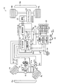
以下、本発明の一実施形態を図面を用いて詳しく説明する。図1および図2は、同実施形態に係る充電制御装置を備えた電動車両としてのゴルフカート10を示している。
このゴルフカート10は、車体11の前部の左右両側にそれぞれ設けられた2個の前輪FL,FRと、車体11の後部の左右両側にそれぞれ設けられた2個の後輪RL,RRとを備えている。また、車体11の中央部の前後に、それぞれ二人用の前部シート12aと三人用の後部シート12bとが並んで設けられている。さらに、車体11の前部における前部シート12aの前側にハンドル13が設けられている。
Hereinafter, an embodiment of the present invention will be described in detail with reference to the drawings. FIG. 1 and FIG. 2 show a
The
また、車体11の上部に、車体11の四隅に設けられた支持枠14aを介して屋根部14が設けられている。そして、車体11の前端下部にバンパ15aが取り付けられ、車体11の後部を構成するカウル11aの後端下部にバンパ15bが取り付けられている。このゴルフカート10は、自動運転または手動運転が可能になっており、手動運転する場合には、前部シート12aに座った運転者がハンドル13を回転操作することにより前部の両前輪FL,FRが左右に向きを変更して、ゴルフカート10は左旋回したり右旋回したりしながら進行方向を変えて走行する。
Further, a
すなわち、ハンドル13は、車体11の前側下部からやや後部側の上方に向って延び軸回り方向に回転可能に設置されたステアリング軸13aの上端に固定されており、ハンドル13を支持するステアリング軸13aの下端は水平方向に設置されたラックバー16に噛合している。このラックバー16は、ステアリング軸13aの回転により左右(ラックバー16の軸方向)に移動し、このラックバー16の移動により左右の前輪FL,FRの向きが変わるように構成されている。また、ステアリング軸13aは下部側部分と上部側部分とで構成されており、その間に、下部側部分と上部側部分とを連結したり切り離したりするためのステアリングクラッチ17が設けられている。
That is, the
このステアリングクラッチ17によってステアリング軸13aの上部側部分と下部側部分とを連結したときには、運転者によるハンドル13の操作に応じて前輪FL,FRが操向される。また、ステアリングクラッチ17によって、ステアリング軸13aの上部側部分が下部側部分から切り離されたときには、ハンドル13は固定されて一定位置に静止する。この場合には、自動運転が行われステアリング軸13aの下部側部分に設けられたステアリングモータ18の作動によって、ステアリング軸13aの下部側部分が回転しその回転に応じて前輪FL,FRは向きを左右に変更する。
When the steering
また、車体11の前部側におけるハンドル13の下方にアクセルペダル21とブレーキペダル22とが並んで設けられ、車体11の後部側には、駆動モータ23および駆動モータ23の駆動力を後輪RL,RRに伝達するためのトランスミッション24等が設けられている。アクセルペダル21およびブレーキペダル22は、ゴルフカート10を走行させる際に、運転者によって操作されるものである。アクセルペダル21は、アクセルポテンショメータ21aを介してコントローラ50に接続されており、運転者がアクセルペダル21を踏み込むとアクセルペダル21の位置(踏込み量)がアクセルポテンショメータ21aによって検出される。
An
そして、アクセルポテンショメータ21aが検出した検出値は、アクセル位置信号として、コントローラ50が備える走行制御部51に送信される。走行制御部51は、マイクロコンピュータを主要部に構成され、アクセルポテンショメータ21aからのアクセル位置信号に基づいて、駆動回路52を介して駆動モータ23を駆動させ、トランスミッション24を介して後輪RL,RRを回転させる。これによって、ゴルフカート10は加速しながら走行する。そして、ゴルフカート10を自動運転させる場合には、走行制御部51の制御によって駆動モータ23を駆動させて後輪RL,RRを回転させる。
And the detected value which the
また、ブレーキペダル22は、油圧式ディスクブレーキシステム(図示せず)を介して、前輪FL,FRおよび後輪RL,RRにそれぞれ設けられたディスクブレーキに連結されるとともに、制動モータ22aを介して走行制御部51に接続されている。そして、ブレーキペダル22には、ブレーキペダル22が操作されたことを検出するためのブレーキスイッチ22bおよびブレーキペダル22を踏み込んだときに生じる油圧を検出するための圧力センサ22cが備わっている。
The
このため、運転者がブレーキペダル22を踏込むと、ブレーキペダル22の踏込み量(踏込み力)は、油圧式ディスクブレーキシステムを介して、前輪FL,FRおよび後輪RL,RRにそれぞれ設けられたディスクブレーキに伝達され、ディスクブレーキの作動により前輪FL,FRおよび後輪RL,RRの回転駆動が制動される。また、自動運転する場合には、走行制御部51の制御によって制動モータ22aが駆動することにより、運転者がブレーキペダル22を踏込んだときと同様に、ディスクブレーキを作動させて前輪FL,FRおよび後輪RL,RRの回転駆動を制動する。その際、ブレーキスイッチ22bは、運転者がブレーキペダル22を踏込んだときに、ブレーキペダル22が操作されたことを検出する。
Therefore, when the driver depresses the
また、ゴルフカート10は、電源スイッチ27、発進・停止スイッチ28を備えている。電源スイッチ28は、キーを差し込んで回転させることによりオン位置とオフ位置とに回転するようになっており、オン位置に回転することにより、ゴルフカート10は走行可能な状態になる。また、電源スイッチ27がオフ位置に回転することによりゴルフカート10は走行不能な状態になる。発進・停止スイッチ28は、ゴルフカート10を発進させたり、停止させたりするためのスイッチであり、その操作状態は、信号として走行制御部51に送信される。そして、電源スイッチ28をオン位置にした状態で、発進・停止スイッチ28を押すことにより、ゴルフカート10は発進を開始し、再度発進・停止スイッチを押すことにより、ゴルフカート10は停止する。
The
ゴルフカート10は、駆動バッテリ30、制御バッテリ31を備えている。駆動バッテリ30は、コントローラ50の駆動回路52を介して駆動モータ23に電源供給するもので、本実施形態においては、定格出力電圧12Vの鉛密閉蓄電池を6台直列に接続して構成される。従って、駆動バッテリ30は、72Vの電源を駆動回路52に供給する。この駆動バッテリ30には、そのケーシング上面にバッテリ温度を検出する温度センサ33が設けられる。温度センサ33は、駆動バッテリ30の温度に応じた信号を出力する。
制御バッテリ31は、定格12Vの汎用の車両用蓄電池で、コントローラ50およびゴルフカート10内の各種電気負荷に電源供給する。
The
The
ゴルフカート10は、こうした駆動バッテリ30および制御バッテリ31を充電するための充電器40を備える。この充電器40は、駆動バッテリ30を充電するための72V充電回路41と、制御バッテリ31を充電するための12V充電回路42とを備える。充電器40には、図示しないプラグ接続口が設けられ、充電ケーブル43の差込プラグ43pをプラグ接続口に接続することによりAC200Vの商用電源を得て、駆動バッテリ30あるいは制御バッテリ31を充電する。
The
コントローラ50には、充電器40の充電動作を制御する充電制御部53とメモリ54とが設けられる。充電制御部53は、マイクロコンピュータを主要部に構成され、後述する充電制御処理を実施する。メモリ54は、走行制御部51おより充電制御部53で実行する制御プログラムや各種の制御データを記憶するROMと、一時的にデータを記憶するRAM,EEPROM等から構成される。
The controller 50 is provided with a
充電制御部53は、駆動バッテリ30の端子電圧Vx(バッテリ電圧Vx)をA/Dコンバータによりデジタル信号に変換して検出する電圧検出回路53aと、温度センサ33からのアナログ信号をA/Dコンバータによりデジタル信号に変換してバッテリ温度Tbを検出する温度検出回路53bとを備える。また、充電制御部53は、通信インタフェース53cを介して充電器40と送受信可能に接続され、後述する充電制御プログラムにしたがって充電器40に制御指令を出力する。
The
次に、充電制御部53の実行する充電制御処理について説明する。
本実施形態の充電制御処理は、駆動バッテリ30の充電処理に特徴があり、制御バッテリ31の充電処理に関しては一般的であるため、以下、駆動バッテリ30の充電制御処理について説明する。
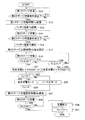
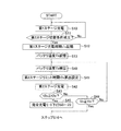
図3は、第1実施形態としての充電制御ルーチンを示すフローチャートで、メモリ54内に制御プログラムとして記憶されている。
本制御ルーチンは、充電器40に充電ケーブル43の差込プラグ43pが接続され、図示しない充電スイッチのオン操作により起動する。
尚、本充電制御ルーチンの説明にあたって、各制御処理ごとに符号Sを用いてステップ番号をつけるが、この制御ステップ番号と充電ステージ数とは無関係である。
Next, the charge control process performed by the
Since the charge control process of the present embodiment is characterized by the charge process of the
FIG. 3 is a flowchart showing a charge control routine as the first embodiment, and is stored in the
This control routine is started by turning on a charging switch (not shown) when the plug 40p of the charging
In the description of this charging control routine, a step number is assigned for each control process using the symbol S, but this control step number and the number of charging stages are irrelevant.
本制御ルーチンが起動すると、まず、第1ステージの充電処理を開始する(S10)。この第1ステージの充電処理は、充電電流を9Aに設定して駆動バッテリ30の充電を行う。このとき、充電制御部53は、駆動バッテリ30に9Aの定電流が流れるように充電器40の72V充電回路41を制御する。尚、第1ステージの開始と同期してタイマを起動し、第1ステージの経過時間t1xを計時する。このタイマは、マイクロコンピュータのソフトウエアタイマで構成すればよい。
When this control routine is activated, first, the first stage charging process is started (S10). In this first stage charging process, the driving
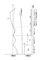
第1ステージの充電処理が開始されると、図8に示すようにバッテリ電圧Vx(充電電圧)は徐々に上昇していく。
この充電中においては、第2ステージへの切替条件が成立したか否かを繰り返し判断する(S11)。本実施形態の充電制御ルーチンでは、4段階の充電ステージを順番に実行するが、ここでは、第1ステージから第2ステージへの切替タイミングを判断する。具体的には、図4に示すフローチャートにそって判断する。
つまり、第1ステージの充電処理を開始してからの経過時間t1xが予め設定した上限時間t1oに達したか否かを判断し(S111)、上限時間t1o内であれば、バッテリ電圧Vxが予め設定した所定電圧Vo(以下、切替電圧Voと呼ぶ)に達したか否かを判断する(S112)。
When the first stage charging process is started, the battery voltage Vx (charging voltage) gradually increases as shown in FIG.
During this charging, it is repeatedly determined whether or not the condition for switching to the second stage is satisfied (S11). In the charging control routine of the present embodiment, four charging stages are executed in order. Here, the switching timing from the first stage to the second stage is determined. Specifically, the determination is made according to the flowchart shown in FIG.
That is, it is determined whether or not the elapsed time t1x from the start of the first stage charging process has reached a preset upper limit time t1o (S111). It is determined whether or not the set predetermined voltage Vo (hereinafter referred to as switching voltage Vo) has been reached (S112).
バッテリ電圧Vxは、図8に示すように、充電開始時には低く、充電時間の経過とともに上昇していく。そして、第1ステージの開始から上限時間t1o経過するまでにバッテリ電圧Vxが切替電圧Voに達すると(S112:YES)、その時点で第2ステージへの切替条件(移行条件)が成立する(S113)。また、上限時間t1o以内にバッテリ電圧Vxが切替電圧Voに達しない場合には(S112:NO)、上限時間t1o経過した時点(S111:YES)で第2ステージへの切替条件が成立する(S113)。 As shown in FIG. 8, the battery voltage Vx is low at the start of charging, and increases as the charging time elapses. When the battery voltage Vx reaches the switching voltage Vo from the start of the first stage until the upper limit time t1o elapses (S112: YES), the switching condition (transition condition) to the second stage is satisfied at that time (S113). ). If the battery voltage Vx does not reach the switching voltage Vo within the upper limit time t1o (S112: NO), the condition for switching to the second stage is satisfied when the upper limit time t1o has elapsed (S111: YES) (S113). ).
定電流多段充電方式においては、充電ステップが進むほど充電電流を低く設定しているため、この第1ステージでは高い充電電流を流すことになる。従って、通常は上限時間t1o経過する前にバッテリ電圧Vxが切替電圧Voに到達する。本実施形態においては、この第1ステージにおいて80%充電されるように充電電流値と切替電圧値とが設定されている。
尚、この第1実施形態においては、バッテリ電圧Vxと経過時間t1xとの両方を判断しているが、ステップS111の処理を省いてステップS112のバッテリ電圧Vxの判定のみで第2ステージへの切替条件を設定してもよい。
In the constant current multi-stage charging method, the charging current is set lower as the charging step proceeds, so that a higher charging current flows in the first stage. Therefore, normally, the battery voltage Vx reaches the switching voltage Vo before the upper limit time t1o elapses. In the present embodiment, the charging current value and the switching voltage value are set so that 80% charging is performed in the first stage.
In the first embodiment, both the battery voltage Vx and the elapsed time t1x are determined, but the process of step S111 is omitted, and only the determination of the battery voltage Vx in step S112 is performed to switch to the second stage. Conditions may be set.
こうして、第2ステージへの切替条件が成立したと判断されると(S11:YES)、続いて、ステップS12の処理に移行し、第1ステージの充電時間t1xをメモリ54に記憶する。各充電ステージにおいては、所定の定電流で駆動バッテリ30を充電することから、この定電流値と第1ステージの充電時間t1xとの積は、駆動バッテリ30への充電電気量に相当するもので、後述する第4ステージの充電時間を決定する算出処理において使用される。
また、温度センサ33からの信号を読み込んでバッテリ温度Tbを検出してメモリ54に記憶する(S13)。この第1ステージ終了時のバッテリ温度Tbは、充電時間t1xと合わせて後述する第4ステージの充電時間を決定する算出処理において使用される。
Thus, when it is determined that the condition for switching to the second stage is satisfied (S11: YES), the process proceeds to step S12, and the charging time t1x of the first stage is stored in the
Further, the signal from the
続いて、第2ステージの充電処理を開始する(S14)。この第2ステージの充電処理は、充電電流を5Aに設定して駆動バッテリ30の充電を行う。このとき、充電制御部53は、駆動バッテリ30に5Aの定電流が流れるように充電器40の72V充電回路41を制御する。また、第2ステージの開始と同期してタイマをリセットし、第2ステージの経過時間t2xを計時する。
Subsequently, the second stage charging process is started (S14). In the second stage charging process, the driving
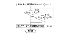
続いて、第3ステージへの切替条件が成立したか否かを判断する(S15)。ここでは、第2ステージから第3ステージへの切替条件の成立判断を図5に示すフローチャートにそって行う。
つまり、上述したステップS11の第2ステージへの切替条件判断と同様に、第2ステージの充電処理を開始してからの経過時間t2xが予め設定した上限時間t2oに達したか否かを判断し(S151)、上限時間t2o内であれば、バッテリ電圧Vxが予め設定した切替電圧Voに達したか否かを判断する(S152)。
そして、第2ステージの開始から上限時間t2o経過するまでにバッテリ電圧Vxが切替電圧Voに達すると(S152:YES)、その時点で第3ステージへの切替条件(移行条件)が成立する(S153)。また、上限時間t2o以内にバッテリ電圧Vxが切替電圧Voに達しない場合には(S152:NO)、上限時間t2o経過した時点(S151:YES)で第3ステージへの切替条件が成立する(S153)。
尚、この第1実施形態においては、バッテリ電圧Vxと経過時間t2xとの両方を判断しているが、ステップS151の処理を省いてステップS152のバッテリ電圧Vxの判定のみで第3ステージへの切替条件を設定してもよい。
Subsequently, it is determined whether or not a condition for switching to the third stage is satisfied (S15). Here, the determination of the switching condition from the second stage to the third stage is made according to the flowchart shown in FIG.
That is, similarly to the determination of the switching condition to the second stage in step S11 described above, it is determined whether or not the elapsed time t2x from the start of the second stage charging process has reached a preset upper limit time t2o. (S151) If it is within the upper limit time t2o, it is determined whether or not the battery voltage Vx has reached a preset switching voltage Vo (S152).
When the battery voltage Vx reaches the switching voltage Vo from the start of the second stage until the upper limit time t2o elapses (S152: YES), the switching condition (transition condition) to the third stage is satisfied at that time (S153). ). If the battery voltage Vx does not reach the switching voltage Vo within the upper limit time t2o (S152: NO), the condition for switching to the third stage is satisfied when the upper limit time t2o has elapsed (S151: YES) (S153). ).
In the first embodiment, both the battery voltage Vx and the elapsed time t2x are determined. However, the process of step S151 is omitted, and the switching to the third stage is performed only by the determination of the battery voltage Vx in step S152. Conditions may be set.
こうして、第3ステージへの切替条件が成立したと判断されると(S15:YES)、次に、ステップS16において、温度センサ33からの信号を読み込んでバッテリ温度Tbを検出する。
続いて、ステップS17に処理を進め、第2ステージ終了時のバッテリ温度Tbに応じて設定される第3ステージの上限時間t3oを算出する。この算出に当たっては、図6に示す算出テーブルが参照される。この例では、上限時間t3oは、バッテリ温度Tbが5℃以下であれば2時間に、15℃以上であれば1.5時間に、5℃〜15℃の範囲では2時間〜1.5時間の間でバッテリ温度Tbが高くなるほど短時間になるように設定される。
尚、このバッテリ温度Tbに対する上限時間t3oの設定は、低温時に対して高温時の上限時間t3oを短く設定すればよく、任意に設定できるものである。
Thus, if it is determined that the condition for switching to the third stage is satisfied (S15: YES), then, in step S16, a signal from the
Subsequently, the process proceeds to step S17, and an upper limit time t3o of the third stage set according to the battery temperature Tb at the end of the second stage is calculated. For this calculation, a calculation table shown in FIG. 6 is referred to. In this example, the upper limit time t3o is 2 hours if the battery temperature Tb is 5 ° C. or lower, 1.5 hours if the battery temperature Tb is 15 ° C. or higher, and 2 hours to 1.5 hours in the range of 5 ° C. to 15 ° C. The battery temperature Tb is set so as to be shorter as the battery temperature Tb increases.
The upper limit time t3o for the battery temperature Tb can be set arbitrarily as long as the upper limit time t3o at the high temperature is set shorter than that at the low temperature.
続いて、第3ステージの充電処理を開始する(S18)。この第3ステージの充電処理は、充電電流を1.5Aに設定して駆動バッテリ30の充電を行う。このとき、充電制御部53は、駆動バッテリ30に1.5Aの定電流が流れるように充電器40の72V充電回路41を制御する。また、第3ステージの開始と同期してタイマをリセットし、第3ステージの経過時間t3xを計時する。
Subsequently, the charging process of the third stage is started (S18). In the third stage charging process, the driving
次に、第3ステージから第4ステージへの切替条件成立を判断するために、ステップS19およびステップS20の判断処理を行う。ステップS19では、第3ステージの充電処理を開始してからの経過時間t3xがステップS17において設定した上限時間t3oに達したか否かを判断する。そして、経過時間t3xが上限時間t3o内であれば、ステップS20において、バッテリ電圧Vxが切替電圧Voに達したか否かを判断する。
この場合、バッテリ電圧Vxが切替電圧Voに達したとき、あるいは、バッテリ電圧Vxの上昇が遅くて切替電圧Voに達する前に先に上限時間t3oが経過したときに第4ステージに移行するが、その切替条件の成立状況に応じて後段の処理が異なる。
Next, in order to determine whether or not the switching condition from the third stage to the fourth stage is satisfied, the determination process of step S19 and step S20 is performed. In step S19, it is determined whether or not the elapsed time t3x from the start of the third stage charging process has reached the upper limit time t3o set in step S17. If the elapsed time t3x is within the upper limit time t3o, it is determined in step S20 whether or not the battery voltage Vx has reached the switching voltage Vo.
In this case, when the battery voltage Vx reaches the switching voltage Vo or when the upper limit time t3o elapses before the battery voltage Vx rises slowly and reaches the switching voltage Vo, the process proceeds to the fourth stage. The subsequent processing differs depending on the establishment condition of the switching condition.
つまり、上限時間t3o内にバッテリ電圧Vxが切替電圧Voに達したケース(S20:YES)においては、完全充電モードサイクルBの値を「5」に設定し(S22)、バッテリ電圧Vxが切替電圧Voに到達する前に充電時間が上限時間t3o経過したケース(S19:YES)においては、完全充電モードサイクルBの値を「10」に設定する(S21)。 That is, in the case where the battery voltage Vx reaches the switching voltage Vo within the upper limit time t3o (S20: YES), the value of the full charge mode cycle B is set to “5” (S22), and the battery voltage Vx is switched to the switching voltage. In the case where the upper limit time t3o has elapsed before reaching Vo (S19: YES), the value of the complete charge mode cycle B is set to “10” (S21).
ここで、完全充電モードサイクルについて説明する。
最終充電ステージとなる第4ステージにおいては、第1ステージで駆動バッテリ30に供給した充電電気量とバッテリ温度Tbとにより、その充電設定時間が算出される。図7は、第4ステージの充電設定時間を算出する算出マップを表す。横軸は、第1ステージ終了時のバッテリ温度Tbを表し、縦軸は、第1ステージで駆動バッテリ30に供給した充電電気量(アンペア×分)を表す。この実施形態においては、第1ステージの充電電気量は、9A×t1xとなる。
Here, the complete charge mode cycle will be described.
In the fourth stage, which is the final charge stage, the charge setting time is calculated from the amount of charge supplied to the
このマップに示すように、第1ステージの充電時間t1xとバッテリ温度Tbとの組み合わせから第4ステージの充電設定時間が設定される。
第1ステージの充電電気量は、駆動バッテリ30の充電前の深度を表したものといえる。そして、この深度に応じて駆動バッテリ30へのトータル充電電気量を設定することで、適切な充電率になるように充電することができる。そこで、この実施形態においては、深度に応じた充電電気量になるように、第4ステージの充電時間を図7に示す算出マップにより設定する。この場合、充電効率がバッテリ温度により変化するため、バッテリ温度Tbが低いほど、第4ステージの充電時間は長く設定される。
As shown in this map, the charge setting time for the fourth stage is set from the combination of the charge time t1x for the first stage and the battery temperature Tb.
It can be said that the amount of charge in the first stage represents the depth of the
また、第4ステージの充電設定時間は、充電モードによって異なる。マップ中に記載された数値のうち、上段の数値はノーマルモードでの充電設定時間を、下段の括弧内数値は完全充電モードでの充電設定時間を表す。例えば、バッテリ温度Tbが30℃で第1ステージ充電時間t1xが100分の場合には、第4ステージの充電設定時間は、ノーマルモードで0.5時間、完全充電モードで2.5時間に設定される。 Further, the charge setting time of the fourth stage varies depending on the charge mode. Among the numerical values described in the map, the upper numerical value indicates the charging setting time in the normal mode, and the lower parenthesis numerical value indicates the charging setting time in the full charging mode. For example, if the battery temperature Tb is 30 ° C. and the first stage charge time t1x is 100 minutes, the charge setting time for the fourth stage is set to 0.5 hours in the normal mode and 2.5 hours in the full charge mode. Is done.
一般に、サイクルユースされる蓄電池の長寿命化を図るためには、放電した分の105%〜125%の充電を行うことが望まれる。100%以下の充電では急激な電池容量低下を招き、125%を超える充電では過充電により蓄電池の早期劣化を招く。
そこで、本実施形態においては、駆動バッテリ30が正常なとき、ノーマルモードにおいては、放電した分の105%充電を行うように時間設定し、完全充電モードにおいては125%充電を行うように時間設定している。そのため、完全充電モードにおいてはノーマルモードよりも充電設定時間が長く設定される。この完全充電モードは、本発明におけるロングモードに相当する。
In general, in order to extend the life of a storage battery that is cycle-used, it is desired to charge 105% to 125% of the discharged battery. If the charging is less than 100%, the battery capacity is suddenly reduced. If the charging is more than 125%, the battery is prematurely deteriorated due to overcharging.
Therefore, in this embodiment, when the
そして、完全充電モードサイクルは、この完全充電モードにて充電を行う周期を表す。例えば、完全充電モードサイクルBの値が「5」に設定されている場合(B=5)には、5回に1回だけ完全充電モードが設定され、残り4回はノーマルモードが設定される。
一般に、ゴルフカート10は、毎日バッテリ充電を行ってから使用されるが、こうした使用状況においては、5日に1回完全充電モードによる充電が行われ、残りの4日はノーマルモードによる充電が行われる。
The full charge mode cycle represents a cycle in which charging is performed in the full charge mode. For example, when the value of the full charge mode cycle B is set to “5” (B = 5), the full charge mode is set only once every 5 times, and the normal mode is set for the remaining 4 times. .
In general, the
図3の制御ルーチンの説明に戻る。
ステップS18の第3ステージ充電中において、上限時間t3o内にバッテリ電圧Vxが切替電圧Voに達した場合(S20:YES)は、駆動バッテリ30が劣化していないと考えられる。この場合には、完全充電モードサイクルBの値が「5」に設定される(S22)。
一方、バッテリ電圧Vxが切替電圧Voに到達する前に充電時間が上限時間t3o経過した場合(S19:YES)は、駆動バッテリ30が劣化していると考えられる。この場合には、完全充電モードサイクルBの値が「10」に設定される(S21)。
つまり、駆動バッテリ30の劣化が検出されない状況であれば、完全充電モードが5回に1回だけ行われるように設定され、駆動バッテリ30の劣化が検出された状況であれば、完全充電モードが10回に1回だけ行われるように設定される。
Returning to the description of the control routine of FIG.
If the battery voltage Vx reaches the switching voltage Vo within the upper limit time t3o during the third stage charging in step S18 (S20: YES), it is considered that the
On the other hand, if the upper limit time t3o has elapsed before the battery voltage Vx reaches the switching voltage Vo (S19: YES), it is considered that the
That is, if the deterioration of the
こうして完全充電モードサイクルBの値が設定されると、続いて、ステップS23において、充電回数をカウントするカウンタの値Cxを読み込み、カウンタ値Cxが完全充電モードサイクルBと等しいか否かを判断する。このカウンタ値Cxは、後述するステップS31の処理で充電が終了するたびに値1だけインクリメントされてメモリ54に記憶される。従って、ステップS23の処理は、メモリ54からカウント値Cxを読み込み、このカウント値Cxが先のステップS21またはステップS22にて設定された完全充電モードサイクルの値Bと等しいか否かを判断する。
When the value of the full charge mode cycle B is set in this way, subsequently, in step S23, a counter value Cx for counting the number of times of charging is read, and it is determined whether or not the counter value Cx is equal to the full charge mode cycle B. . This counter value Cx is incremented by 1 and stored in the
そして、カウンタ値Cxが完全充電モードサイクルの値Bと等しければ(Cx=B)、充電モードを完全充電モードに設定し(S24)、そうでなければノーマルモードに設定する(S25)。また、完全充電モードを設定した場合には、カウンタ値Cxをゼロクリアする(S26)。
こうしてモード設定が完了すると、続いて、ステップS27の処理に移行し、第4ステージの充電設定時間t4oを算出する。この算出に当たっては、図7の算出マップに基づいて、上述したように充電モードに応じた充電設定時間t4oが算出される。
If the counter value Cx is equal to the value B of the full charge mode cycle (Cx = B), the charge mode is set to the full charge mode (S24). Otherwise, the normal mode is set (S25). When the complete charge mode is set, the counter value Cx is cleared to zero (S26).
When the mode setting is completed in this way, the process proceeds to step S27, and the charge setting time t4o of the fourth stage is calculated. In this calculation, the charge setting time t4o corresponding to the charge mode is calculated as described above based on the calculation map of FIG.
続いて、第4ステージの充電処理を開始する(S28)。この第4ステージの充電処理は、充電電流を1.5Aに設定して駆動バッテリ30の充電を行う。このとき、充電制御部53は、駆動バッテリ30に1.5Aの定電流が流れるように充電器40の72V充電回路41を制御する。また、第4ステージの開始と同期してタイマをリセットし、第4ステージの経過時間t4xを計時する。
Subsequently, the charging process of the fourth stage is started (S28). In the charging process of the fourth stage, the driving
充電中においては、経過時間t4xを常に確認し、経過時間t4xが充電設定時間t4oに達すると(S29:YES)、第4ステージの充電処理を終了する(S30)。この場合、図示しない充電完了ランプ等を作動させて使用者に充電完了を知らせる。
続いて、ステップS31において、カウンタのカウント値Cxの値を1だけインクリメンする。従って、今回の充電処理が完全充電モードであればカウンタ値Cxは値「1」にセットされ、ノーマルモードであればカウンタ値Cxは値1だけ増加する。
During charging, the elapsed time t4x is always checked, and when the elapsed time t4x reaches the charging set time t4o (S29: YES), the fourth stage charging process is terminated (S30). In this case, a charging completion lamp or the like (not shown) is operated to notify the user of the completion of charging.
Subsequently, in step S31, the count value Cx of the counter is incremented by 1. Accordingly, if the current charging process is the full charge mode, the counter value Cx is set to the value “1”, and if the current charging process is the normal mode, the counter value Cx is increased by the
従って、ステップS23で使用されるカウンタ値Cxは、前回の完全充電モードから何回目の充電であるかを表す値となる。例えば、完全充電モードサイクルの値Bが「5」に設定されていれば、カウンタ値Cx=5になるたびに、つまり、5回に1回だけ完全充電モードが設定される。このため、Bの値を設定することで、完全充電モードの周期を調整することができる。
こうしてステップS31の処理が完了すると本充電制御ルーチンは終了する。
Therefore, the counter value Cx used in step S23 is a value representing the number of times of charging since the previous full charge mode. For example, if the value B of the full charge mode cycle is set to “5”, the full charge mode is set every time the counter value Cx = 5, that is, once every five times. For this reason, the period of complete charge mode can be adjusted by setting the value of B.
When the process of step S31 is completed in this way, the present charging control routine ends.
この第1実施形態にかかる充電制御ルーチンによれば、後段の充電ステージへの移行を、バッテリ電圧と上限時間とに基づいて行っているため、駆動バッテリ30の劣化状態にかかわらず最終の第4ステージまで進めることができる。また、後段ステージにいくほど充電電流値が低いため、バッテリの劣化しているケースではバッテリ電圧の上昇が得られにくいが、第3ステージから第4ステージ(最終ステージ)への切替に関しては、第3ステージの上限時間t3oを第2ステージ終了時のバッテリ温度Tbに応じて設定しているため、充電効率を加味した適切な上限時間にすることができる。従って、第3ステージにおける駆動バッテリ30の充電過不足を抑制することができる。
According to the charging control routine according to the first embodiment, since the transition to the subsequent charging stage is performed based on the battery voltage and the upper limit time, the final fourth stage is performed regardless of the deterioration state of the
また、第3ステージから第4ステージに移行したときのステップ移行成立条件に応じて、完全充電モードサイクルBの値を変更しているため、駆動バッテリ30への過充電を抑制しバッテリ早期劣化を防止できる。つまり、バッテリ電圧Vxが切替電圧Voに到達する前に充電時間が上限時間t3oに達した場合は、駆動バッテリ30の劣化度合いが高く充電時間も長くなっているため、完全充電モードを行う頻度を少なくして過充電を抑制している。
Further, since the value of the full charge mode cycle B is changed according to the step transition establishment condition at the time of transition from the third stage to the fourth stage, overcharge to the
例えば、メモリ54に記憶されているカウンタ値Cxが「5」のときに充電処理が開始された場合を考えると、駆動バッテリ30が劣化していなければ完全充電モードによる充電が行われる(S20→S22→S23→S24)。
しかし、駆動バッテリ30が劣化しておりバッテリ電圧Vxが切替電圧Voに到達する前に充電時間が上限時間t3oに達した場合には、モード設定処理が行われる前に完全充電モードサイクルBの値が「10」に変更されるため、完全充電モードがキャンセルされることになる(S19→S21→S23→S25)。この場合、駆動バッテリ30の劣化状態が変わらなければ、さらに5回目の充電時に完全充電モードに設定される。
尚、完全充電モードがキャンセルされた後、駆動バッテリ30の状態が回復した場合には、カウンタ値Cxが完全充電モードサイクルの値Bより大きくなってしまうが(例えば、Cx=7,B=5)、こうした場合には、カウンタ値Cxをゼロクリアするとよい。
For example, considering the case where the charging process is started when the counter value Cx stored in the
However, if the
When the state of the
本実施形態の駆動バッテリ30は、放電量に対する適正充電率が105%〜125%であり、100%を下回ると急激な容量低下を招き、125%を超えると過充電によりバッテリの早期劣化が生じる。このため、本充電制御ルーチンにおいては、駆動バッテリ30が正常なときは、ノーマルモードで充電率105%の充電を行い、完全充電モードで充電率125%の充電を行うように充電電流値、切替電圧Vo、第4ステージ充電時間t4oが設定される。このため、完全充電モードサイクルBが「5」に設定されている場合には、5回に1回の完全充電モードの実施により平均充電率は109%となり((105×4+125)/5=109)、良好な充電率を維持することができる。
The
一方、駆動バッテリ30が劣化してバッテリ電圧Vxが切替電圧Voに到達する前に充電時間が上限時間t3oに達した場合には、充電時間が長くなるため充電率が大きくなる。この場合、例えば、ノーマルモードで充電率122%、完全充電モードで充電率135%に上昇する。しかし、完全充電モードサイクルBが「10」に変更されることで、平均充電率を123.3%((122×9+135)/10)=123.3)に抑えることができる。
On the other hand, when the charging time reaches the upper limit time t3o before the
これに対して、上限時間t3oをバッテリ温度Tbに応じて変更せずに固定値とし、しかも、完全充電モードサイクルBの値を固定設定したケースを考えると、駆動バッテリ30が劣化している場合には、平均充電率を適正範囲に維持できない。参考として、低温時の充電不足を防止するために上限時間を長めの固定値に設定した例を挙げると、充電率は、例えば、ノーマルモードで140%、完全充電モードで160%に上昇する。この場合、完全充電モードサイクルBの値を「5」に固定した構成では、平均充電率が144%((130×4+160)/5=144)に達してしまいバッテリ早期劣化を招くことになる。
On the other hand, when the upper limit time t3o is set to a fixed value without changing according to the battery temperature Tb, and the value of the full charge mode cycle B is fixed, the
また、第4ステージの充電設定時間t4oは、第1ステージにおける充電電気量(9A×t1x)とバッテリ温度Tbと充電モードとにより設定されるため、極めて適正な時間となる。つまり、第1ステージにおける充電電気量により駆動バッテリ30の充電前の深度を推定し、最終的にこの深度に応じた適切な充電電気量が供給されるように、第4ステージにおける充電時間を決定する。この場合、図7のマップに示すように、充電効率に影響を与えるバッテリ温度Tbに応じて第4ステージの充電時間を調整するため、放電量に対して105%〜125%の適正な充電を行うことができる。この結果、充電不足による急激な容量低下と、過充電によるバッテリ早期劣化を抑制することができる。
Further, the charge setting time t4o of the fourth stage is an extremely appropriate time because it is set by the charge electricity amount (9A × t1x), the battery temperature Tb, and the charge mode in the first stage. That is, the depth before the
これらの結果、本実施形態におけるゴルフカート10は、適正に充電された駆動バッテリ30を使って走行するため、走行時間を長くすることができるとともに、バッテリ寿命も長くなり、バッテリ交換といったメンテナンスを低減することができる。
As a result, since the
次に、第2実施形態としての充電制御処理について説明する。図9は、充電制御部53が実行する第2実施形態としての充電制御ルーチンを示すフローチャートで、メモリ54内に制御プログラムとして記憶されている。
Next, the charge control process as 2nd Embodiment is demonstrated. FIG. 9 is a flowchart showing a charge control routine as the second embodiment executed by the
この第2実施形態の充電制御ルーチンは、第1実施形態の充電制御ルーチンのステップS14〜S15における第3ステージへの切替条件を変更したものであり、他の処理については同一である。従って、以下、第1実施形態と相違する処理についてのみ説明する。
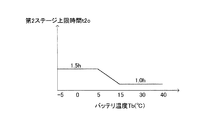
第2実施形態の充電制御ルーチンでは、第1ステージの充電が完了して充電時間t1xおよびバッテリ温度Tbをメモリ54に記憶すると(S12,S13)、続いて、このバッテリ温度Tbに応じて設定される第2ステージの上限時間t2oを算出する(S41)。この算出に当たっては、図10に示す算出テーブルが参照される。この例では、上限時間t2oは、バッテリ温度Tbが5℃以下であれば1.5時間に、15℃以上であれば1.0時間に、5℃〜15℃の範囲では1.5時間〜1.0時間の間でバッテリ温度Tbが高くなるほど短時間になるように設定される。
The charge control routine of the second embodiment is obtained by changing the switching condition to the third stage in steps S14 to S15 of the charge control routine of the first embodiment, and the other processes are the same. Therefore, hereinafter, only processing different from the first embodiment will be described.
In the charging control routine of the second embodiment, when the charging of the first stage is completed and the charging time t1x and the battery temperature Tb are stored in the memory 54 (S12, S13), subsequently, the charging is set according to the battery temperature Tb. The second stage upper limit time t2o is calculated (S41). For this calculation, a calculation table shown in FIG. 10 is referred to. In this example, the upper limit time t2o is 1.5 hours if the battery temperature Tb is 5 ° C. or lower, 1.0 hours if the battery temperature Tb is 15 ° C. or higher, 1.5 hours in the range of 5 ° C. to 15 ° C. The battery temperature Tb is set to be shorter as the battery temperature Tb is higher during 1.0 hour.
続いて、第2ステージの充電処理を開始する(S42)。この第2ステージの充電処理は、第1実施形態のステップS14と同一であり、充電電流を5Aに設定して駆動バッテリ30の充電を行う。また、第2ステージの開始と同期してタイマをリセットし、第2ステージの経過時間t2xを計時する。
次に、第2ステージから第3ステージへの切替条件成立を判断するために、ステップS43およびステップS44の判断処理を行う。ステップS43では、第2ステージの充電処理を開始してからの経過時間t2xがステップS41において設定した上限時間t2oに達したか否かを判断する。そして、経過時間t2xが上限時間t2o内であれば、ステップS44において、バッテリ電圧Vxが切替電圧Voに達したか否かを判断する。
Subsequently, the second stage charging process is started (S42). The charging process in the second stage is the same as step S14 in the first embodiment, and the driving
Next, in order to determine whether the switching condition from the second stage to the third stage is satisfied, the determination processing of step S43 and step S44 is performed. In step S43, it is determined whether or not the elapsed time t2x from the start of the second stage charging process has reached the upper limit time t2o set in step S41. If the elapsed time t2x is within the upper limit time t2o, it is determined in step S44 whether or not the battery voltage Vx has reached the switching voltage Vo.
充電中にこうした判断を繰り返し、上限時間t2o内にバッテリ電圧Vxが切替電圧Voに達した場合には(S44:YES)、そのままステップS16の処理に進めるが、バッテリ電圧Vxが切替電圧Voに到達する前に充電時間が上限時間t2o経過した場合には(S43:YES)、完全充電モードサイクルBの値を「20」に設定して(S45)ステップS16の処理に進める。ステップS16からの処理は第1実施形態と同一である。 Such determination is repeated during charging, and when the battery voltage Vx reaches the switching voltage Vo within the upper limit time t2o (S44: YES), the process proceeds to step S16 as it is, but the battery voltage Vx reaches the switching voltage Vo. If the upper limit time t2o elapses before starting (S43: YES), the value of the complete charge mode cycle B is set to “20” (S45), and the process proceeds to step S16. The processing from step S16 is the same as in the first embodiment.
第2ステージにおいては充電電流5Aにて充電するため、バッテリ電圧Vxの上昇が得られやすいはずであるが、バッテリが大きく劣化している場合には、図11の破線にて示すように、バッテリ電圧Vxが上限時間t2o内に切替電圧Voに到達しないケースが生じる。
そこで、この第2実施形態では、第2ステージの上限時間t2oを第1ステージ終了時のバッテリ温度Tbに応じて設定しているため、こうしたケースにおいても第2ステージでの充電過不足を抑制することができる。
しかも、この場合、第2ステージだけでなく第3ステージにおいてもバッテリ電圧Vxが切替電圧Voに到達しないため、最終的に充電時間が長くなってしまい、正常時と比べて充電率が大きくなる。そこで、この第2実施形態では、完全充電モードを行う頻度を少なくすることで過充電を抑制している。
In the second stage, since charging is performed with the charging current 5A, it should be easy to obtain an increase in the battery voltage Vx. However, when the battery is greatly deteriorated, as shown by the broken line in FIG. There is a case where the voltage Vx does not reach the switching voltage Vo within the upper limit time t2o.
Therefore, in the second embodiment, since the upper limit time t2o of the second stage is set according to the battery temperature Tb at the end of the first stage, even in such a case, overcharge and shortage in the second stage are suppressed. be able to.
In addition, in this case, since the battery voltage Vx does not reach the switching voltage Vo not only in the second stage but also in the third stage, the charging time eventually becomes longer, and the charging rate becomes larger than that in the normal state. Therefore, in the second embodiment, overcharge is suppressed by reducing the frequency of performing the full charge mode.
尚、第2実施形態においては、完全充電モードサイクルBの値は、第2ステージ終了時のステップS45と、第3ステージ終了時のステップS21,S22にて算出されるが、最終的にステップS23においてカウンタ値Cxと比べる値Bは、それらのうちの最大値Bmaxが採用される(S23:Cx=Bmax?)。例えば、完全充電モードサイクルBの値がステップS45において値20に設定された場合には、ステップS21において値10に設定されても、その最大値である値20が採用される。
In the second embodiment, the value of the full charge mode cycle B is calculated in step S45 at the end of the second stage and steps S21 and S22 at the end of the third stage, but finally in step S23. As the value B to be compared with the counter value Cx, the maximum value Bmax among them is adopted (S23: Cx = Bmax?). For example, when the value of the full charge mode cycle B is set to the
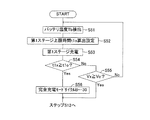
次に、第3実施形態としての充電制御処理について説明する。図12は、充電制御装置53が実行する第3実施形態としての充電制御ルーチンを示すフローチャートで、メモリ54内に制御プログラムとして記憶されている。
Next, the charge control process as 3rd Embodiment is demonstrated. FIG. 12 is a flowchart showing a charge control routine as a third embodiment executed by the
この第3実施形態の充電制御ルーチンは、第2実施形態の充電制御ルーチンのステップS10〜S11における第1ステージから第2ステージへの切替条件を変更したものであり、他の処理については同一である。従って、以下、第2実施形態と相違する処理についてのみ説明する。
第3実施形態の充電制御ルーチンは、第1ステージの上限時間t1oを第1ステージの充電開始するときのバッテリ温度Tbに応じて可変したものである。
つまり、本制御ルーチンの起動時に、温度センサ33からの信号を読み込んでバッテリ温度Tbを検出し(S51)、バッテリ温度Tbに応じて設定される第1ステージの上限時間t1oを算出する(S52)。この算出に当たっては、図13に示す算出テーブルが参照される。この例では、上限時間t1oは、バッテリ温度Tbが5℃以下であれば5時間に、15℃以上であれば3時間に、5℃〜15℃の範囲では5時間〜3時間の間でバッテリ温度Tbが高くなるほど短時間になるように設定される。
The charge control routine of the third embodiment is obtained by changing the switching condition from the first stage to the second stage in steps S10 to S11 of the charge control routine of the second embodiment, and the other processes are the same. is there. Therefore, only processing different from the second embodiment will be described below.
In the charge control routine of the third embodiment, the upper limit time t1o of the first stage is varied according to the battery temperature Tb when charging of the first stage is started.
That is, at the time of starting this control routine, a signal from the
続いて、第1ステージの充電処理を開始する(S53)。この第1ステージの充電処理は、第1実施形態のステップS10と同一であり、充電電流を9Aに設定して駆動バッテリ30の充電を行う。また、第1ステージの開始と同期してタイマをリセットし、第1ステージの経過時間t1xを計時する。
次に、第1ステージから第2ステージへの切替条件成立を判断するために、ステップS54およびステップS55の判断処理を行う。ステップS54では、第1ステージの充電処理を開始してからの経過時間t1xがステップS52において設定した上限時間t1oに達したか否かを判断する。そして、経過時間t1xが上限時間t1o内であれば、ステップS55において、バッテリ電圧Vxが切替電圧Voに達したか否かを判断する。
Subsequently, the first stage charging process is started (S53). This first stage charging process is the same as step S10 of the first embodiment, and the
Next, in order to determine whether the switching condition from the first stage to the second stage is satisfied, the determination processing of step S54 and step S55 is performed. In step S54, it is determined whether or not the elapsed time t1x from the start of the first stage charging process has reached the upper limit time t1o set in step S52. If the elapsed time t1x is within the upper limit time t1o, it is determined in step S55 whether or not the battery voltage Vx has reached the switching voltage Vo.
充電中にこうした判断を繰り返し、上限時間t1o内にバッテリ電圧Vxが切替電圧Voに達した場合には(S55:YES)、そのままステップS12の処理に進めるが、バッテリ電圧Vxが切替電圧Voに到達する前に充電時間が上限時間t1o経過した場合には(S54:YES)、完全充電モードサイクルBの値を「30」に設定して(S56)ステップS12の処理に進める。ステップS12からの処理は第2実施形態と同一である。 Such determination is repeated during charging. If the battery voltage Vx reaches the switching voltage Vo within the upper limit time t1o (S55: YES), the process proceeds to step S12 as it is, but the battery voltage Vx reaches the switching voltage Vo. If the upper limit time t1o elapses before starting (S54: YES), the value of the complete charge mode cycle B is set to “30” (S56), and the process proceeds to step S12. The processing from step S12 is the same as in the second embodiment.
第1ステージにおいては充電電流9Aにて充電するため、バッテリ電圧Vxの上昇が得られるはずであるが、バッテリが極端に劣化している場合には、図14の破線にて示すように、バッテリ電圧Vxが上限時間t1o内に切替電圧Voに到達しないケースが生じる。
そこで、この第3実施形態では、第1ステージの上限時間t1oを充電開始する時のバッテリ温度Tbに応じて設定しているため、こうしたケースにおいても第1ステージでの充電過不足を抑制することができる。
しかも、この場合、第1ステージだけでなく、第2ステージ、第3ステージにおいてもバッテリ電圧Vxが切替電圧Voに達しないため、最終的に充電時間がかなり長くなってしまい、正常時と比べて充電率が大きくなる。そこで、この第3実施形態では、完全充電モードを行う頻度をさらに少なくすることで過充電を抑制している。
In the first stage, charging is performed with the charging current 9A, so that an increase in the battery voltage Vx should be obtained. However, when the battery is extremely deteriorated, as shown by the broken line in FIG. There is a case where the voltage Vx does not reach the switching voltage Vo within the upper limit time t1o.
Therefore, in the third embodiment, since the upper limit time t1o of the first stage is set according to the battery temperature Tb at the time of starting charging, it is possible to suppress overcharging and undercharging in the first stage even in such a case. Can do.
Moreover, in this case, since the battery voltage Vx does not reach the switching voltage Vo not only in the first stage but also in the second stage and the third stage, the charging time eventually becomes considerably long, compared with the normal stage. The charging rate increases. Therefore, in the third embodiment, overcharge is suppressed by further reducing the frequency of performing the full charge mode.
尚、第3実施形態においても、完全充電モードサイクルBの値が複数回設定される場合があるが(S56,S45、S21,S22)、最終的にステップS23においてカウンタ値Cxと比べる値Bは、それらの最大値Bmaxを採用する(S23:Cx=Bmax?)。 In the third embodiment, the value of the complete charge mode cycle B may be set a plurality of times (S56, S45, S21, S22), but finally the value B to be compared with the counter value Cx in step S23 is The maximum value Bmax is adopted (S23: Cx = Bmax?).
次に、上述した3つの実施形態における変形例について説明する。
上述した3つの実施形態においては、第nステージの上限時間tno(n=1,2,3)は、直前段(n−1段)のステージ終了時のバッテリ温度Tbに基づいて算出した。これに対して、変形例では、当該ステージの充電中にバッテリ温度Tbの検出を繰り返し行って、最新の検出値を用いて上限時間tnoを更新設定するものである。
Next, modifications of the above-described three embodiments will be described.
In the three embodiments described above, the upper limit time tno (n = 1, 2, 3) of the nth stage is calculated based on the battery temperature Tb at the end of the immediately preceding stage (n−1 stage). On the other hand, in the modification, the detection of the battery temperature Tb is repeatedly performed during charging of the stage, and the upper limit time tno is updated and set using the latest detection value.
例えば、第1実施形態の変形例においては、図15に示すように、第3ステージの充電中に繰り返しバッテリ温度Tbを検出し、その最新検出値に基づいて第3ステージの上限時間t3oを毎回算出して更新設定する(S16〜S20)。
駆動バッテリ30の充電中においては、バッテリ温度Tbが漸増していく。従って、これに伴って上限時間t3oは漸減する。このため、この変形例においては、最適な上限時間設定が行われるため、バッテリ劣化が生じている場合でも、さらに適正な充電率にすることができる。
For example, in the modification of the first embodiment, as shown in FIG. 15, the battery temperature Tb is repeatedly detected during charging of the third stage, and the upper limit time t3o of the third stage is determined each time based on the latest detection value. Calculate and update settings (S16 to S20).
While the
同様に、第2実施形態の変形例においては、図16に示すように、ステップS40〜ステップS44の繰り返し処理において、バッテリ温度Tbに基づく上限時間t2oの更新設定が繰り返される。
また、同様に、第3実施形態の変形例においては、図17に示すように、ステップS51〜ステップS55の繰り返し処理において、バッテリ温度Tbに基づく上限時間t1oの更新設定が繰り返される。
Similarly, in the modified example of the second embodiment, as shown in FIG. 16, the update setting of the upper limit time t2o based on the battery temperature Tb is repeated in the repeated processing of step S40 to step S44.
Similarly, in the modified example of the third embodiment, as shown in FIG. 17, the update setting of the upper limit time t <b> 1 o based on the battery temperature Tb is repeated in the repeated processing of step S <b> 51 to step S <b> 55.
以上、本発明の3つの実施形態および変形例について説明したが、本発明の実施にあたっては、上記実施形態や変形例に限定されるものではなく、本発明の目的を逸脱しない限りにおいて種々の変更が可能である。 The three embodiments and modifications of the present invention have been described above. However, the present invention is not limited to the above-described embodiments and modifications, and various modifications can be made without departing from the object of the present invention. Is possible.
例えば、本実施形態では、ゴルフカートの駆動バッテリを充電するための充電制御装置について説明したが、ゴルフカートへの適用になんら限定するものではない。また、本実施形態で示した数値(バッテリ電圧値、充電電流値、充電ステージ数、上限時間、充電率等)は任意に設定することができるものであって、これに限るものではない。また、充電モードを変更しないタイプのものであってもよい。 For example, although this embodiment demonstrated the charge control apparatus for charging the drive battery of a golf cart, it is not limited to the application to a golf cart at all. The numerical values (battery voltage value, charging current value, number of charging stages, upper limit time, charging rate, etc.) shown in the present embodiment can be arbitrarily set, and are not limited thereto. Moreover, the type which does not change charging mode may be sufficient.
尚、本実施形態における充電制御部53、メモリ54、温度センサ33、充電器40からなる構成が本発明の充電制御装置に相当する。また、本実施形態における電圧検出回路53aが本発明の電池電圧検出手段に相当し、本実施形態における温度センサ33および温度検出回路53bが本発明の電池温度検出手段に相当し、本実施形態における充電制御部53が実行する充電制御ルーチンのステップS17,S41,S52の処理が本発明の上限時間設定手段に相当し、本実施形態における充電制御部53が実行する充電制御ルーチンのステップS20,S44,S55の処理が本発明の電圧判定手段に相当し、本実施形態における充電制御部53が実行する充電制御ルーチンのステップS19,S43,S54が本発明のタイムアップ判定手段に相当し、本実施形態における充電制御部53が実行する充電制御ルーチンのステップS18〜S20の処理が本発明のステージ切替制御手段に相当する。
In addition, the structure which consists of the
また、本実施形態における充電制御部53が実行する充電制御ルーチンのステップS24〜S25の処理が本発明の充電モード切替手段に相当し、本実施形態における充電制御部53が実行する充電制御ルーチンのステップS31の処理が本発明の充電回数カウント手段に相当し、本実施形態における充電制御部53が実行する充電制御ルーチンのステップS23〜S25の処理が本発明の充電モード選択手段に相当する。
Further, the processing of steps S24 to S25 of the charge control routine executed by the
また、本実施形態における充電制御部53が実行する充電制御ルーチンのステップS21,S22,S45,S56の処理が本発明のモードサイクル変更手段に相当し、本実施形態における充電制御部53が実行する充電制御ルーチンのステップS27の処理が本発明の最終充電ステージ時間決定手段に相当する。
Moreover, the process of step S21, S22, S45, S56 of the charge control routine which the
10…ゴルフカート、23…駆動モータ、30…駆動バッテリ、31…制御バッテリ、33…温度センサ、40…充電器、41…72V充電回路、42…12V充電回路、50…コントローラ、51…走行制御部、52…駆動回路、53…充電制御部、53a…電圧検出回路、53b…温度検出回路、53c…通信インタフェース、54…メモリ、Tb…バッテリ温度、Vx…バッテリ電圧。
DESCRIPTION OF
Claims (7)
蓄電池の電圧を検出する電池電圧検出手段と、
蓄電池の温度を検出する電池温度検出手段と、
上記電池温度検出手段により検出される電池温度に応じて充電ステージの上限時間を設定する上限時間設定手段と、
上記電池電圧検出手段により検出される電池電圧が所定の切替電圧に達したか否かを判定する電圧判定手段と、
上記充電ステージの充電開始から計時し、上記上限時間設定手段により設定される充電ステージの上限時間に達したか否かを判定するタイムアップ判定手段と、
最終充電ステージの少なくとも1回前の充電ステージから最終充電ステージまでの移行を、上記電圧判定手段により電池電圧が上記切替電圧に達したと判定された電圧判定出力、あるいは、上記タイムアップ判定手段により上記上限時間に達したと判定された時間判定出力の何れか一方を受けたときに行うステージ切替制御手段と、
上記最終充電ステージを充電時間の短いノーマルモードと充電時間の長いロングモードとに切り替える充電モード切替手段と、
上記初回充電ステージから最終充電ステージまでの充電動作を1回の充電動作として充電動作回数をカウントする充電回数カウント手段と、
予め設定された所定充電回数おきに上記ロングモードを選択し、それ以外はノーマルモードを選択して、選択した充電モードを上記充電モード切替手段に指令する充電モード選択手段と
を備えたことを特徴とする充電制御装置。 Charge control equipped with a charger that charges the storage battery, and performing multiple charging stages from the initial charging stage to the final charging stage in order by setting the charging current value of each charging stage to be equal to or lower than the current value of the immediately preceding charging stage In the device
Battery voltage detection means for detecting the voltage of the storage battery;
Battery temperature detecting means for detecting the temperature of the storage battery;
Upper limit time setting means for setting the upper limit time of the charging stage according to the battery temperature detected by the battery temperature detecting means;
Voltage determination means for determining whether or not the battery voltage detected by the battery voltage detection means has reached a predetermined switching voltage;
Time-up determination means for measuring whether or not the charging stage has reached the upper limit time set by the upper limit time setting means, counting from the start of charging of the charging stage;
The transition from the charging stage to the final charging stage at least once before the final charging stage is performed by the voltage determination output determined by the voltage determination means that the battery voltage has reached the switching voltage, or by the time-up determination means. Stage switching control means for performing any one of the time determination outputs determined to have reached the upper limit time ;
Charging mode switching means for switching the final charging stage between a normal mode with a short charging time and a long mode with a long charging time;
Charge number counting means for counting the number of charge operations as a single charge operation from the first charge stage to the final charge stage,
Charging mode selection means for selecting the long mode every predetermined number of times set in advance, selecting the normal mode otherwise, and instructing the selected charging mode to the charging mode switching means Charge control device.
上記モードサイクル変更手段は、上記電圧判定手段により電池電圧が上記切替電圧に達したと判定される前に上記タイムアップ判定手段により上記上限時間に達したと判定されて次の充電ステージに移行した場合、上記上限時間の到達判定がなされた充電ステージが早い段階であるほど上記ロングモードを選択するサイクルを長く設定することを特徴とする請求項3記載の充電制御装置。 The stage switching control means is configured to change the voltage determination means to transition to the next charging stage in each charging stage from the charging stage n times before the final charging stage (natural number satisfying n> 1) to the final charging stage. When the battery voltage is determined to have reached either the voltage determination output determined to have reached the switching voltage, or the time determination output determined to have reached the upper limit time by the time-up determination means,
The mode cycle changing means determines that the upper limit time has been reached by the time-up determining means before the voltage determining means determines that the battery voltage has reached the switching voltage, and has shifted to the next charging stage. 4. The charging control device according to claim 3 , wherein the cycle for selecting the long mode is set to be longer as the charge stage at which the upper limit time is determined to be reached is earlier.
上記上限時間設定手段は、上記検出された蓄電池の温度に応じて、上記上限時間を逐次更新していくことを特徴とする請求項1ないし請求項5の何れかに記載の充電制御装置。 The battery temperature detecting means repeatedly detects the temperature of the storage battery during the charging stage,
The upper limit time setting means, said in response to the detected temperature of the battery, the charging control apparatus according to any one of claims 5 claim 1, characterized in that to continue to sequentially update the upper limit time.
Priority Applications (3)
| Application Number | Priority Date | Filing Date | Title |
|---|---|---|---|
| JP2006144051A JP4657148B2 (en) | 2006-05-24 | 2006-05-24 | Charge control device |
| KR1020070024950A KR101301164B1 (en) | 2006-05-24 | 2007-03-14 | Charge control device |
| US11/753,410 US7525290B2 (en) | 2006-05-24 | 2007-05-24 | Charge control device for executing a plurality of charge stages |
Applications Claiming Priority (1)
| Application Number | Priority Date | Filing Date | Title |
|---|---|---|---|
| JP2006144051A JP4657148B2 (en) | 2006-05-24 | 2006-05-24 | Charge control device |
Publications (2)
| Publication Number | Publication Date |
|---|---|
| JP2007318863A JP2007318863A (en) | 2007-12-06 |
| JP4657148B2 true JP4657148B2 (en) | 2011-03-23 |
Family
ID=38789327
Family Applications (1)
| Application Number | Title | Priority Date | Filing Date |
|---|---|---|---|
| JP2006144051A Expired - Fee Related JP4657148B2 (en) | 2006-05-24 | 2006-05-24 | Charge control device |
Country Status (3)
| Country | Link |
|---|---|
| US (1) | US7525290B2 (en) |
| JP (1) | JP4657148B2 (en) |
| KR (1) | KR101301164B1 (en) |
Families Citing this family (22)
| Publication number | Priority date | Publication date | Assignee | Title |
|---|---|---|---|---|
| JP2008067426A (en) * | 2006-09-04 | 2008-03-21 | Yamaha Motor Electronics Co Ltd | Vehicular charge control method |
| JP5268085B2 (en) * | 2007-01-10 | 2013-08-21 | ヤマハモーターパワープロダクツ株式会社 | Battery capacity management device |
| US8063609B2 (en) * | 2008-07-24 | 2011-11-22 | General Electric Company | Method and system for extending life of a vehicle energy storage device |
| US8212532B2 (en) * | 2008-07-24 | 2012-07-03 | General Electric Company | Method and system for control of a vehicle energy storage device |
| US8350533B2 (en) * | 2009-05-04 | 2013-01-08 | Apple Inc. | Portable electronic device having automatic low temperature battery charging capability |
| JP5381534B2 (en) * | 2009-09-14 | 2014-01-08 | 株式会社リコー | Secondary battery charging circuit |
| US20110302078A1 (en) | 2010-06-02 | 2011-12-08 | Bryan Marc Failing | Managing an energy transfer between a vehicle and an energy transfer system |
| JP5327151B2 (en) * | 2010-07-01 | 2013-10-30 | 株式会社デンソー | Emergency call system |
| JP5677917B2 (en) * | 2011-09-13 | 2015-02-25 | 本田技研工業株式会社 | Charge control device |
| JP5839210B2 (en) * | 2011-10-04 | 2016-01-06 | エルジー・ケム・リミテッド | Battery charging apparatus and method |
| JP5392334B2 (en) * | 2011-10-07 | 2014-01-22 | 日産自動車株式会社 | Charger |
| JP5880008B2 (en) * | 2011-12-19 | 2016-03-08 | マツダ株式会社 | In-vehicle power supply controller |
| WO2013102204A1 (en) * | 2011-12-30 | 2013-07-04 | Club Car Llc | Charging system for fleet golf cart |
| US9190782B2 (en) | 2012-04-30 | 2015-11-17 | Club Car, Llc | Power connection system |
| US9312712B2 (en) * | 2012-07-26 | 2016-04-12 | Samsung Sdi Co., Ltd. | Method and system for controlling charging parameters of a battery using a plurality of temperature ranges and counters and parameter sets |
| JP2014053134A (en) * | 2012-09-06 | 2014-03-20 | Sony Corp | Secondary battery, process of manufacturing the same, battery pack, and electric vehicle |
| EP3159999B1 (en) | 2014-07-16 | 2019-01-16 | Huawei Technologies Co., Ltd. | Electronic device quick charging method, apparatus and device |
| JP6537886B2 (en) * | 2015-05-18 | 2019-07-03 | エイブリック株式会社 | Constant current charging device |
| JP6583009B2 (en) * | 2016-01-19 | 2019-10-02 | スズキ株式会社 | Vehicle charging / discharging device |
| KR101867995B1 (en) * | 2016-11-22 | 2018-06-20 | 주식회사 더원전기 | Method and apparatus for charging battery with overcharge protection |
| KR102516362B1 (en) * | 2017-12-19 | 2023-03-31 | 삼성전자주식회사 | Method and apparatus for battery charging |
| CN110783652B (en) | 2019-10-23 | 2021-06-29 | 北京小米移动软件有限公司 | Battery charging method, battery charging device and storage medium |
Citations (4)
| Publication number | Priority date | Publication date | Assignee | Title |
|---|---|---|---|---|
| JPS6237023A (en) * | 1985-08-08 | 1987-02-18 | 沖電気工業株式会社 | Charge controlling circuit |
| JPH07123602A (en) * | 1993-10-19 | 1995-05-12 | Sanyo Electric Co Ltd | Method for charging secondary battery |
| JP2002315216A (en) * | 2001-04-05 | 2002-10-25 | Yamaha Motor Co Ltd | Boosting charger for motor-operated golf cart |
| JP2006114312A (en) * | 2004-10-14 | 2006-04-27 | Matsushita Electric Ind Co Ltd | Charging method of lead acid storage battery |
Family Cites Families (2)
| Publication number | Priority date | Publication date | Assignee | Title |
|---|---|---|---|---|
| JPH11136876A (en) * | 1997-10-28 | 1999-05-21 | Shin Kobe Electric Mach Co Ltd | Charging of lead-acid battery |
| JP2001128385A (en) | 1999-10-25 | 2001-05-11 | Yamaha Motor Co Ltd | Power supply system for motor vehicle |
-
2006
- 2006-05-24 JP JP2006144051A patent/JP4657148B2/en not_active Expired - Fee Related
-
2007
- 2007-03-14 KR KR1020070024950A patent/KR101301164B1/en active IP Right Grant
- 2007-05-24 US US11/753,410 patent/US7525290B2/en not_active Expired - Fee Related
Patent Citations (4)
| Publication number | Priority date | Publication date | Assignee | Title |
|---|---|---|---|---|
| JPS6237023A (en) * | 1985-08-08 | 1987-02-18 | 沖電気工業株式会社 | Charge controlling circuit |
| JPH07123602A (en) * | 1993-10-19 | 1995-05-12 | Sanyo Electric Co Ltd | Method for charging secondary battery |
| JP2002315216A (en) * | 2001-04-05 | 2002-10-25 | Yamaha Motor Co Ltd | Boosting charger for motor-operated golf cart |
| JP2006114312A (en) * | 2004-10-14 | 2006-04-27 | Matsushita Electric Ind Co Ltd | Charging method of lead acid storage battery |
Also Published As
| Publication number | Publication date |
|---|---|
| US7525290B2 (en) | 2009-04-28 |
| KR101301164B1 (en) | 2013-09-03 |
| KR20070113100A (en) | 2007-11-28 |
| US20070278991A1 (en) | 2007-12-06 |
| JP2007318863A (en) | 2007-12-06 |
Similar Documents
| Publication | Publication Date | Title |
|---|---|---|
| JP4657148B2 (en) | Charge control device | |
| JP4906921B2 (en) | Control device and control method for electrical system | |
| JP4039355B2 (en) | Secondary battery control device and control method | |
| JP4386138B1 (en) | Control device and control method for hybrid vehicle | |
| JP6136784B2 (en) | vehicle | |
| JP3560867B2 (en) | Hybrid vehicle battery control device | |
| JP5267675B2 (en) | VEHICLE CHARGE SYSTEM AND ELECTRIC VEHICLE HAVING THE SAME | |
| JP3901100B2 (en) | Automatic charging system | |
| US9878702B2 (en) | Method for operating a motor vehicle and the motor vehicle | |
| US20120262125A1 (en) | Method and charge control for prolonging the useful life of batteries | |
| CN104662769A (en) | Charging control device and charging time calculation method | |
| JP2006256416A (en) | Power supply unit for bicycle | |
| EP1967446B1 (en) | Motorized assist bicycle | |
| JP2005132122A (en) | Speed change control device for bicycle | |
| JP5704747B2 (en) | Charge control unit | |
| KR101487560B1 (en) | Electric power supply for industrial vehicle and control method thereof | |
| JPH11146505A (en) | Control device for charging battery for motorized vehicle | |
| JP2000197212A (en) | Power supply system for motor-driven car | |
| JP7419901B2 (en) | electric vehicle | |
| JP5136612B2 (en) | Hybrid vehicle power generation control device | |
| JP4992738B2 (en) | Charging unit | |
| JP2009051242A (en) | Voltage conversion device for hybrid electric vehicle | |
| JP3772735B2 (en) | Cell voltage detector | |
| JP2021126037A (en) | Vehicular control device | |
| JP6874652B2 (en) | Battery system |
Legal Events
| Date | Code | Title | Description |
|---|---|---|---|
| A711 | Notification of change in applicant |
Free format text: JAPANESE INTERMEDIATE CODE: A712 Effective date: 20090127 |
|
| A621 | Written request for application examination |
Free format text: JAPANESE INTERMEDIATE CODE: A621 Effective date: 20090415 |
|
| A977 | Report on retrieval |
Free format text: JAPANESE INTERMEDIATE CODE: A971007 Effective date: 20100205 |
|
| A131 | Notification of reasons for refusal |
Free format text: JAPANESE INTERMEDIATE CODE: A131 Effective date: 20100407 |
|
| A521 | Request for written amendment filed |
Free format text: JAPANESE INTERMEDIATE CODE: A523 Effective date: 20100524 |
|
| TRDD | Decision of grant or rejection written | ||
| A01 | Written decision to grant a patent or to grant a registration (utility model) |
Free format text: JAPANESE INTERMEDIATE CODE: A01 Effective date: 20101221 |
|
| A01 | Written decision to grant a patent or to grant a registration (utility model) |
Free format text: JAPANESE INTERMEDIATE CODE: A01 |
|
| A61 | First payment of annual fees (during grant procedure) |
Free format text: JAPANESE INTERMEDIATE CODE: A61 Effective date: 20101221 |
|
| FPAY | Renewal fee payment (event date is renewal date of database) |
Free format text: PAYMENT UNTIL: 20140107 Year of fee payment: 3 |
|
| R150 | Certificate of patent or registration of utility model |
Ref document number: 4657148 Country of ref document: JP Free format text: JAPANESE INTERMEDIATE CODE: R150 Free format text: JAPANESE INTERMEDIATE CODE: R150 |
|
| R250 | Receipt of annual fees |
Free format text: JAPANESE INTERMEDIATE CODE: R250 |
|
| R250 | Receipt of annual fees |
Free format text: JAPANESE INTERMEDIATE CODE: R250 |
|
| R250 | Receipt of annual fees |
Free format text: JAPANESE INTERMEDIATE CODE: R250 |
|
| R250 | Receipt of annual fees |
Free format text: JAPANESE INTERMEDIATE CODE: R250 |
|
| R250 | Receipt of annual fees |
Free format text: JAPANESE INTERMEDIATE CODE: R250 |
|
| R250 | Receipt of annual fees |
Free format text: JAPANESE INTERMEDIATE CODE: R250 |
|
| R250 | Receipt of annual fees |
Free format text: JAPANESE INTERMEDIATE CODE: R250 |
|
| R250 | Receipt of annual fees |
Free format text: JAPANESE INTERMEDIATE CODE: R250 |
|
| LAPS | Cancellation because of no payment of annual fees |