JP4656738B2 - Single-axle truck for railway vehicles - Google Patents
Single-axle truck for railway vehicles Download PDFInfo
- Publication number
- JP4656738B2 JP4656738B2 JP2001034669A JP2001034669A JP4656738B2 JP 4656738 B2 JP4656738 B2 JP 4656738B2 JP 2001034669 A JP2001034669 A JP 2001034669A JP 2001034669 A JP2001034669 A JP 2001034669A JP 4656738 B2 JP4656738 B2 JP 4656738B2
- Authority
- JP
- Japan
- Prior art keywords
- link
- vehicle body
- axle
- carriage
- frame
- Prior art date
- Legal status (The legal status is an assumption and is not a legal conclusion. Google has not performed a legal analysis and makes no representation as to the accuracy of the status listed.)
- Expired - Fee Related
Links
Images


Landscapes
- Vehicle Body Suspensions (AREA)
Description
【0001】
【発明の属する技術分野】
この発明は、鉄道車両用1軸台車、特に鉄道車両のうち低床式路面電車に適する一軸台車(台車枠に一つの車軸を備えた)に関する。
【0002】
【従来の技術】
近年、省エネルギー、低公害およびバリアフリーなどの特性を有することから、LRV(Light Rail Vehicle)と称される路面電車が再評価され、欧米をはじめ各都市で導入が進んでいる。この種の路面電車は、車両重量が軽く、軌道上を走行する台車部分を一軸台車で構成することができる。一軸台車は周知のように、台車枠には左右に車輪を備えた車軸を一つしか設けていないことから、台車がピッチングしやすいという欠点がある。
【0003】
そこで、たとえば車両の床面が軌道上からかなり高い位置(800mm〜1100mm)に位置している高床式の一軸台車では、台車枠の前後に上下一対のラジアスロッドを配置して、これらのロッドの踏ん張りによってピッチングを防止するようにした、DSB(DanskeStadsBanen)と称される構造の台車が提案されている。
【0004】
その他の先行技術として、特開平10−250573号公報に記載の一軸台車がある。この台車は、1本の輪軸の両端を台車枠に支持し、この台車枠と車体との間に複数個の枕ばねを介して車体を支持し、前記台車枠と前記車体とを前後方向の相対的な移動を規制する牽引機構により連結した構造からなっている。
【0005】
また、特許第2788047号掲載公報に記載の台車がある。この台車は台車枠に対し前後2つの車軸の中央部が軸受手段を介してハの字形リンクにより支持されるとともに、スリ板を介して台車の旋回時に車軸の前後方向および左右方向の摺動が可能なように構成されている。
【0006】
【発明が解決しようとする課題】
しかしながら、上記した従来のDSB台車および上記の2件の公報に記載の台車では、次のような点で不都合がある。
【0007】
すなわち、車両の床面の高さが軌道から300mm程度しかない低床式の路面電車に適用しようとすると、台車が配置される位置の床面をかなり高くする必要があり、床面に凹凸が生じる。いいかえれば、100%低床式の路面電車には適用できない。
【0008】
また、2両編成の車両において車両の連結(連接)部間に配置される連接台車として適用することも、構造的に困難である。
さらに、特許第2788047号掲載公報に記載の台車は二軸台車であり、また各車軸は左右の車輪を直接結合して回転するいわゆる串軸であるから、一軸台車を対象とし、左右の車輪を別々に支持する、いわゆる独立車輪を用いる本発明の台車には適用することができない。
【0009】
本発明は上述の点に鑑みなされたもので、構造が簡単で軽量で、一軸でピッチングを防止することができ、乗り心地が良好で、低床式の路面電車にも適用可能である鉄道車両用一軸台車を提供することを目的としている。
【0010】
【課題を解決するための手段】
請求項1の発明は、車輪が車軸又はそれに代わる構成部材に支持されており、この車軸又はそれに代わる構成部材を保持する台車枠が4つの枕ばねにて車体を支持する鉄道車両用1軸台車であって、前記台車枠の前後部分が車体に対し、それぞれ前側及び後側リンク機構を介して連結され、前記各リンク機構が、前記台車枠側に比べて車体側の幅方向の間隔が広くなるように平面視略ハの字状に配置され、かつ平面視における軸線の延長線の交点が車体の幅方向の中心軸線上に位置する左右のリンク部材を備え、前記左右のリンク部材の軸線の延長線の交点を仮想旋回中心として旋回可能に構成され、前記リンク部材は、側面視において、その軸線の延長線が左右の車輪とレールとの接触点を通過する構成とされ、前記前側および後側のリンク機構のうち、左側または右側の前後2つのリンク部材が、それぞれトーションバーで結合されていることを特徴とする。
【0011】
請求項1の発明によれば、前側および後側リンク機構を介して台車枠の前後部分が車体に支持され、左右いずれの側においても前後に位置するリンク部材によって台車枠が支持される。そして、その前後に位置するリンク部材の軸線の延長線が、車輪とレールとの接触点を通過するように傾斜して配置されているので、例えば図1に示すように、車輪13に作用する駆動力F1は、側面視で台車枠11の前後を支持するリンク部材14A,14Cの軸線の延長線の方向の力FAと力FBとに分解されることとなる(FA=FB=F1/2cosα)。この力FA,FBが作用する方向は、いずれもリンク部材14A,14Cの軸線方向と一致しているため、ピッチングモーメントは生じないことになる。なお、図1において、3は車体、15は軸箱守り部材、16は軸箱、17は軸ばね、18は枕ばねである。
【0012】
さらに、前側あるいは後側のリンク機構を構成する左右のリンク部材は、平面視で略ハの字状に配置され、かつ平面視における軸線の延長線がほぼ車体の幅方向の中心軸線上(ほぼ車両の幅方向の中心軸線)で交差するから、この交点を一軸台車の仮想旋回中心として旋回する。この構成により、台車旋回用の中心ピンを設ける必要がなくなり、台車枠の側はり付近にリンク部材の連結箇所を設けることができる。よって、車体と台車との間での力の受け渡しを、側はり付近で行なうことができるようになり、その力の受け渡しを車体の幅方向の中心軸線上付近で行なうよりも、台車枠の強度面からは有利とされる。車体についても、台車からの力が左右の側はり付近に伝達されることになるので、車体の台枠を構成する上で有利である。
【0013】
さらに、台車旋回用の中心ピンを設ける場合は、中央の1カ所で荷重を負担するのに対して、前後側リンク機構を用いて、平面視略ハの字状に配置された左右のリンク部材で台車枠の前後部分を支持する場合には、4カ所(4つのリンク部材)に荷重を分散して支持できるようになるので、台車枠および車体の台枠の荷重負担が軽減される。
また、左側または右側の前後の2つのリンク部材が同位相で上下方向に変位する場合(上下の並進またはローリングに相当)にはトーションバーは一緒に変位し抵抗にならないが、前記前後の2つのリンク部材が逆位相で上下方向に変位する場合(ピッチングに相当)には、トーションバーがねじれ、その変位に対し抵抗となり、ピッチングが規制される。
請求項1の発明においては、台車枠を車体に連結するのに通常のリンク部材を用いているが、請求項2の発明に記載のように、請求項1のリンク部材に代えて、少なくとも一部に板層とゴム層とが交互に配置されてなる積層ゴム部を有する複合リンク部材を用いるようにすることもできる。即ち、請求項2の発明は、車輪が車軸又はそれに代わる構成部材に支持されており、この車軸又はそれに代わる構成部材を保持する台車枠が4つの枕ばねにて車体を支持する鉄道車両用1軸台車であって、前記台車枠の前後部分が車体に対し、それぞれ前側及び後側リンク機構を介して連結され、前記各リンク機構が、前記台車枠側に比べて車体側の幅方向の間隔が広くなるように平面視略ハの字状に配置され、かつ平面視における軸線の延長線の交点が車体の幅方向の中心軸線上に位置する左右のリンク部材を備え、前記左右のリンク部材の軸線の延長線の交点を仮想旋回中心として旋回可能に構成され、前記リンク部材は、側面視において、その軸線の延長線が左右の車輪とレールとの接触点を通過する構成とされ、前記各リンク部材は、少なくとも一部に板層とゴム層とが交互に配置されてなる積層ゴム部を有する複合リンク部材であることを特徴とする。
請求項2の発明によれば、台車の前後方向に作用する駆動力は、積層ゴム部が圧縮されることで複合リンク部材により車体に伝達され、その場合複合リンク部材の圧縮に対する剛性は高いため、無駄なく車体側に伝達される。一方、複合リンク部材のせん断変形に対する剛性は低く、積層ゴム部の部位でせん断方向に変形しやすいため台車の旋回、左右方向の並進については、このせん断変形によって無理なく吸収される。よって、通常のリンク部材を用いる場合のように、連結端部に弾性体を設けるなどの工夫をしなくても、積層ゴム部を有する複合リンク部材が、連結端部に弾性体を設けるなどの工夫をした場合のリンク部材と同様に機能し、ピッチングが防止される。
【0014】
請求項3に記載のように、前記台車枠が、前記左右の車輪の中心位置よりも下方に位置する部分を有し、その部分に前記左右のリンク部材が連結されているようにすることが望ましい。この場合、前記左右のリンク部材の台車枠への連結点が、レール踏面から100mm〜300mmの高さに位置するようにすることが望ましい。
【0015】
請求項3の発明によれば、前記台車枠の、前記左右の車輪の中心位置よりも下方に位置する部分に、車体牽引のための前記左右のリンク部材が連結され、リンク部材の台車枠への連結点が従来の台車に比べて低くなるので、ピッチングモーメントが小さくなる。よって、前側および後側のリンク機構において左右のリンク部材の台車枠への連結点の高さを低くすることで、ピッチングの低減と低床化の両立が図れる。
【0016】
前述したように、前側および後側のリンク機構を用いて台車枠を支持するようにすると、上下方向に作用する力も前後のリンク部材の軸線方向と一致する成分に分解され、その上下方向の運動に対する剛性が高くなるおそれがあるので、請求項4に記載のように、前記各リンク部材の一端部又は両端部が、弾性部材を介して結合され、あるいはリンク部材のリンク長さが伸縮可能であるように構成されることが望ましい。
【0017】
請求項4の発明によれば、弾性部材の弾性変形やリンク部材の伸縮動作によって、各リンク部材の左右方向及び上下方向変位が許容され、台車が上下方向において運動しやすくなる。
【0024】
さらに、請求項5に記載のように、左右方向に回転可能に車体又は台車枠に基端部が軸支された第1のヒンジ部材と、上下方向に回転可能に台車枠又は車体に基端部が軸支された第2のヒンジ部材と、第1及び第2のヒンジ部材の先端部を、左右方向及び上下方向に回転可能に結合する十字形部材とを備えるようにすることもできる。
【0025】
請求項5の発明によれば、台車枠がピッチングしようとすると、台車枠に基端部が軸支された第2又は第1のヒンジ部材を傾けることになるが、十字形部材を介して連結される第1又は第2のヒンジ部材によってその動きが規制され、結局、傾かないことになる。よって、ピッチングが防止される。
【0026】
【発明の実施の形態】
以下、この発明の実施の形態を図面に沿って説明する。
【0027】
図2は本発明の実施の形態に係る一軸台車を適用した100%低床式単一車両を示す側面図、図3は本発明の実施の形態に係る一軸台車を適用した100%低床式2両編成の連接車両を示す側面図である。
【0028】
図2および図3に示すように、本発明に係る各路面電車である単一車両1および連接車両1’は、床面2が軌道としてのレール9から300mm若しくは330mmの高さに位置する100%低床式に構成され、台車は全て一軸台車10からなり、床面2は一軸台車10の位置で幅がやや狭くなっているが、車体3の全長にわたり平坦な床面とされている。
【0029】
図4〜図6(a)(b)に示すように、連接車両1の右端および単一車両1の左端および連接車両1’の左端の一軸台車10は、同一の構成で、平面視矩形状の台車枠11、車軸又はそれに代わる構成部材としてのU字形状の非回転式の車軸部材12、車輪13および前側および後側のリンク機構14,14’を備え、左右の車輪13は車軸13aに取り付けられ、この車軸13aを、軸箱16および軸ばね17を介して、台車枠11が保持するようになっている。
【0030】
前記台車枠11は、平面視で幅方向に長い矩形状の基部11aと、その基部11aの左右両側部に設けられ中央位置に略ロの字形状の軸箱守り部材15を両側から支持する、略L字形状の支持部11bとにより形成されている。前記軸箱守り部材15内には、車輪13の車軸13aを支持する軸箱16が上下方向に移動可能に設けられ、軸箱守り部材15の上辺部15aと軸箱16との間に、1次系サスペンションを構成する積層ゴムや圧縮スプリングなどの弾性体からなる軸ばね17が介設されている。
【0031】
前記台車枠11の支持部11bの前後端部付近には、空気ばね、ゴムばね、コイルばねなどの弾性体からなる4つの枕ばね18が設置され、この4つの枕ばね18上にて車体3を台車枠11に支持させることで、2次系サスペンションを構成している。
【0032】
左右の一対の車輪13が後方より見て上向きに凹状の非回転式の車軸部材12の両側に、軸受(図示せず)を介して左右独立して回転可能に支持されており(図6(b)参照)、このように構成される車輪13の車軸13aは、左右の軸箱16を支持している。
【0033】
前記台車枠11の前側および後側部分は、それぞれ前側および後側のリンク機構14,14’を介して車体3に結合されているが、このリンク機構14,14’は、それぞれ、前記台車枠11側に比べて車体3側の幅方向の間隔が広くなるように平面視略ハの字状に配置された一対のリンク部材14A,14B,14C,14Dを備えている。このリンク部材14A〜14Dは、一端部14Aa,14Ba,14Ca,14Da(先端側)が台車枠11に球面軸受(図示せず)により全方向に揺動自在に結合されている(図5参照)。このリンク部材14A〜14Dの一端部14Aa〜14Daは、弾性部材(例えばゴムブッシュ)を介して結合され、台車10が上下方向に移動できるようにされている。なお、このような台車10の上下方向の動きを許容できるするため、他端部14Ab〜14Dbも弾性部材を介して結合するようにしてもよいし、他端部14Ab〜14Dbのみ弾性部材を介して結合するようにしてもよい。さらには、弾性部材を介して結合するのに代えて、リンク部材14A〜14Dを、リンク長さが伸縮可能であるように構成するようにしてもよい。
【0034】
また、前記台車枠11全体が、前記左右の車輪13の中心位置(軸芯位置)よりも下方に位置している。そして、前記台車枠11の前後側部分に前記左右のリンク部材14A〜14Dの一端部14Aa〜14Daを連結し、前記左右のリンク部材14A〜14Dの台車枠11への連結点が、前記左右の車輪13の回転中心位置よりも下方に位置するようにしている。具体的には、左右のリンク部材14A〜14Dの台車枠11への連結点が、レール踏面から100mm〜300mmの高さに位置するようにされる。
【0035】
一方、リンク部材14A〜14Dの他端部14Ab,14Bb,14Cb,14Db(基端側)は車体3に対し、ブラケット20を介して、垂直方向の上端側が下端側に比べて車軸部材12の中心側へ傾斜した傾斜軸回りに(または垂直軸回りに)回転可能に軸支(連結)されている。また、リンク部材14A〜14Dの他端部14Ab〜14Dbは車体3に軸支されているが、一端部14Aa〜14Daよりも上方に位置し、かつ一端部14Aa〜14Daよりも車両外方側に位置するように傾斜するように配設されている。そして、前記リンク部材14A,14Cは、側面視において、リンク部材14A,14C(14B,14D)の軸線の延長線PA,PCが車輪13の踏面とレール9との接触点を通過するように構成されている(図4参照)。前記リンク部材14B,14Dについても同様である。
【0036】
また、各リンク部材14A〜14Dは、平面視において前後の両端部14Aa,14Ba,14Ca,14Da,14Ab,14Bb,14Cb,14Dbを結ぶ直線である軸線を延ばした延長線PA,PB,PC,PDが、車軸部材12の近傍で、車体幅方向の中心位置を前後方向に通過する中心軸線CLと交差して、交点Oになる(図5参照)。
【0037】
なお、前記リンク部材14A〜14Dの一端部14Aa〜14Daと台車枠11との結合部分における球面軸受に代えて、ユニバーサルジョイント又はゴムなどの弾性体を用いて全方向の揺動を許容するように連結することもできるのはいうまでもない。
【0038】
このようにして一軸台車10が構成されるが、単一車両1の右端および連接車両1’の右端の一軸台車10’についても構成は共通している。また、連接車両1’の連接箇所に配置される一軸台車10”は、一軸台車10と共通のものを使用することができるが、図7および図8に示すように、一方の車体3’から他方の台車側に、先端に半球面状の受け部21aを有するアーム部21が延ばされる一方、他方の台車の車体3”から前記一方の台車側に、前記受け部21aに揺動可能に係合する係合凸部22aを有する別のアーム部22が延ばされ、前記受け部21aに係合凸部22aが係合することで、連接部分が1つの一軸台車10”によって支持されるようになっている。
【0039】
このように構成すれば、側面視において、前後に位置するリンク部材14A〜14Dの車体3に対する結合位置と台車枠11に対する結合位置とを結ぶ作用線に一致する軸線の延長線PA〜PDが、車輪13とレール9との接触点付近を通過するように、前記リンク部材14A〜14Dを傾斜させて配置しているから、レール9と車輪13の踏面との接触点に前後方向の接線力(具体的には駆動力や制動力)が作用しても、その接線力はリンク部材14A(14B)およびリンク部材14C(14D)の軸線の延長線の方向の成分に分解され、ピッチングモーメントを生じないこととなり、台車10をピッチングさせることがない(図1参照)。
【0040】
この場合、前側および後側のリンク機構14,14’を用いて台車枠11を支持するようにしていることから、上下方向に作用する力も前後のリンク部材14A,14Bおよび14C,14Dの軸線方向と一致する成分に分解され、その上下方向の運動が拘束される傾向となるが、前記各リンク部材14A〜14Dの一端部14Aa〜14Daが弾性部材を介して結合されるようにしているので、多少の伸縮が可能とされ、台車10(台車枠11)が上下に移動可能となる。
【0041】
平面視略ハの字状に配置された一対のリンク部材14A,14Bあるいは14C,14Dは、平面視でリンク部材14A〜14Dの軸線の延長線PA〜PDがほぼ車体の幅方向の中心軸線CL上(ほぼ車両の幅方向の中心)で交差するようにしているから、この交点Oを仮想旋回中心として一軸台車10が旋回するようになる。この構成により、台車10には台車旋回用の中心ピンを設ける必要がなく、台車枠11の側部(側はり)付近にリンク部材14A〜14Dの連結箇所を設けることができる。
【0042】
このような構成とすることは、上記した低床式路面電車1,1’の場合には、特に有利である。これは、車体3の側部(側はり)に強度を持たす構造でないと、低床化に不利であることから、台車10からの力の伝達が車体中央でなく、車体3の両側部(側はり)付近に力が伝達されることが、車体3の台枠の強度面から有利であるからである。それに加えて、台車旋回用の中心ピンを用いる場合は中央の1カ所で荷重を負担するのに対して、平面視略ハの字状に配置した4つのリンク部材14A〜14Dを用いる場合は4カ所に分散して荷重を負担することになるので、台車枠11および車体3の台枠の荷重負担を軽減することができる。
【0043】
また、一軸台車10は車軸部材12に一対の車輪13がそれぞれ回転自在に支持され、また軸箱守り部材15に対し軸箱16が上下方向に摺動可能に支持され、軸箱16と軸箱守り部材15との間の軸ばね17により1次系のサスペンションが構成される。また、台車枠11は、前述したリンク機構14を介して車体3に結合され、この状態で台車枠11は球面軸受(図示せず)を支点として上下方向に揺動可能に支持され、台車枠11と車体3との枕ばね18により2次系のサスペンションが構成される。車体3は、このように軸ばね17による1次系のサスペンションと、枕ばね18による2次系のサスペンションとの2つ系統のサスペンションで上下に揺動自在に支持されるために、乗り心地が良好である。
【0044】
そして、図9及び図10に示すように、一軸台車10が車体3に対し相対的に左旋回した場合には、車軸部材12の近傍に位置する前記交点Oを仮想旋回中心として、車軸13aおよび台車枠11等が一体的に旋回する。このとき、各リンク部材14A〜14Dは、図9に示す状態から図10に示す状態に変位するとともに、枕ばね18が変形する。このようにして、曲線状のレール9に沿って一軸台車10が旋回し、レール9の直線部に進入すると元の状態に旋回して戻る。
【0045】
また、図11および図12に示すように、平面視で略ハの字状に配置され台車枠11に先端部が回転可能に連結された左右のリンク部材14A〜14Dの基端部を、平行リンク機構を介して車体3に連結し、左右の並進運動能力を増加させるようにすることもできる。
【0046】
具体的には、平面視略ハの字状に配置された左右のリンク部材14A,14Bあるいは14C,14Dの基端部が、左右方向に延びるリンク部材41A,41Bの左右端部に鉛直軸回りに回転可能に連結されるとともに、別のリンク部材42A,42B,42C,42Dの先端部に鉛直軸回りに回転可能に連結されている。別のリンク部材42A,42B,42C,42Dの基端部は、ブラケット43A〜43Dを介して、車体3に鉛直軸回りに回転可能に連結されている。この場合、平行リンク機構40,40Aは、車体3側に設けているが、台車枠11側に設けるようにしてもよい。
【0047】
このようにすれば、左右の並進運動能力が増加し、台車枠11と車体3との間に生ずる車体幅方向の相対変位が、平行リンク機構40,40Aによって、吸収緩和され、スムーズな走行が実現されるようになる。
【0048】
また、トーションバーを用いて、図13および図14に示すように前後のリンク機構を構成し、ピッチングの防止を図ることも可能である。
【0049】
すなわち、図13および図14に示すように、前記リンク部材14A〜14Dのうち、左側における前後2つのリンク部材14A,14Cがトーションバー51によって結合されている。トーションバー51は、車両の前後方向に延び前後端部がリンク部材14A,14C付近まで延びるトーションバー基部51aと、このバー基部51aの前後端部より各リンク部材14A,14Cに平行に車体内方側に延びる延長バー部51b,51cとを備える。そして、バー基部51aは、一定間隔を存して配設された2つの取付部材52(台車枠11への取付部材52)によって車体に回転可能に支持され、前記延長バー部51b,51cの先端部がそれぞれリンク部材14A,14Cに取付部材53を介して支持されている。
【0050】
このようにすれば、前後のリンク部材14A,14Cが同位相で上下方向に変位する場合(上下の並進またはローリングに相当)にはトーションバー51は抵抗にならないが、前後のリンク部材14A,14Cが逆位相で上下方向に変位する場合(ピッチングに相当)には、トーションバー51が抵抗となり、ピッチングが規制される。
【0051】
その場合、トーションバー51の動作は、図15(a)〜(e)に示すとおりである。すなわち、通常時には、図15(a)に示す基準状態にある。前後のリンク部材14A,14Cが共に上方に変位したり(図15(b)参照)、共に下方に変位したり(図15(c))した場合には、同位相の変位であり、トーションバー基部51aにはねじりが生じないので、その変位は許容される。その一方、図15(d)に示すように、前側のリンク部材14Aが上方に変位する一方、後側のリンク部材14Cが下方に変位する場合には、トーションバー基部51aにねじりが生じ、その変位に対して抵抗となるように機能し、結果としてピッチングが防止される。また、図15(e)に示すように、前側のリンク部材14Aが下方に変位する一方、後側のリンク部材14Cが上方に変位する場合も、同様である。
【0052】
また、図16に示すように、図13および図14に示す場合とは逆に、延長バー部が車体外方側に延びるようにトーションバーを設けるようにしてもよい。この場合は、トーションバー51’は、車両の前後方向に延び前後端部がリンク部材14A,14C付近まで延びるトーションバー基部51a’と、このバー基部51a’の前後端部より各リンク部材14A,14Cに平行に車体外方側に延びる延長バー部51b’,51c’とを備える。そして、バー基部51a’は、一定間隔を存して配設された2つの取付部材52’(台車枠11への取付部材)によって回転可能に支持され、前記延長バー部51b’、51c’の先端部がそれぞれリンク部材53’に支持されている。
【0053】
図17および図18に示すように、積層ゴム部を有する複合リンク部材を、前述したリンク部材14A〜14Dに代えて用いるようにしてもよい。
【0054】
すなわち、台車枠11の前側および後側部分が、積層ゴム部61Aa〜61Daを有し平面視略ハの字状に配置された複合リンク部材61A〜61Dでもって車体3に結合されている。積層ゴム部61Aa〜61Daは、板(金属板)層とゴム層とが交互に配置されてなる部分を有する。複合リンク部材は、前記実施の形態のリンク部材と同様に、平面視における複合リンク部材の軸線の延長線の交点が車体の幅方向の中心軸線上に位置し、前記左右のリンク部材の軸線の延長線の交点を仮想旋回中心として旋回可能に構成され、その軸線の延長線が左右の車輪とレールとの接触点を通過するようになっている。
【0055】
さらに、前述したような前側および後側リンク機構14,14’を用いることなく、図19に示すような上下2段の平行リンク機構71を用いて、台車のピッチングを防止するようにしてもよい。また、具体的に図示していないが、車軸部材12との干渉を回避するために、平行リンク機構を前後に2組設けたり、あるいは車軸部材を前後に逃がすことも必要に応じて行われる。
【0056】
前記車体3と台車枠11とは、進行方向に沿った鉛直面内に配設された上下2段の平行リンク機構71を介して結合されている。上下2段の平行リンク機構71は、1対のリンク72A,72Bおよび73A,73Bが上下方向において屈曲可能に(水平軸回りに回転可能に)連結されてなる前側および後側リンク部材72,73を有し、リンク72A,72Bおよび73A,73Bの連結部分が、進行方向に延びる別のリンク74の前後端部に水平軸回りに回転可能に連結されている。よって、リンク74の進行方向における進退と各リンク部材72,73の屈曲とが関連づけられる。また、上側に位置するリンク72A,73Aの上端部が車体3に水平軸回りに回転可能に連結される一方、下側に位置するリンク72B,73Bの下端部が、台車枠11から対向するように進行方向において突設された前側および後側ブラケット75,76に水平軸回りに回転可能に連結されている。
【0057】
このようにすれば、車体3と台車枠11との上下方向における相対変位は、上下2段の平行リンク機構71の変位によって許容されるが、前後方向の変位は、平行リンク機構71が変位できないので、車体と台車枠11との間は平行が維持され、ピッチングが防止される。特に、1段の平行リンク機構では、上下動に前後動が連動するが、上下2段の平行リンク機構とすることで、上下動しても、前後動は生じないようにされる。なお、台車10の旋回に対しては、平行リンク機構の面のねじれ変形で対応することとなる。
【0058】
さらに、また、図20および図21に示すような2枚ヒンジ機構を用いて、台車のピッチングを防止するようにすることも可能である。
【0059】
すなわち、鉛直軸回りに左右方向(枕木方向)に回転可能に車体3の突出部3aに、先端部がU字形状とされた第1のヒンジ部材81の基端部が軸支される一方、レール9と平行な軸回りに上下方向に回転可能に台車枠11(ブラケット11c)に、先端部がU字形状とされた第2のヒンジ部材82の基端部が軸支され、第1及び第2のヒンジ部材81,82のU字形状の先端部が十字形部材83を介して、左右方向及び鉛直方向に回転可能に結合されている。十字形部材83は、鉛直軸部83aと水平軸部83bとが直交するように結合されてなり、鉛直軸部83aに第1のヒンジ部材81の先端部が、水平軸部83bに第2のヒンジ部材82の先端部がそれぞれ回転可能に結合されている。
【0060】
このようにすれば、台車枠11がピッチングしようとすると、台車枠11に基端部が軸支された第2のヒンジ部材82を傾けることになるが、十字形部材83を介して連結される第1のヒンジ部材81によってその動きが規制され、結局傾かないことになる。よって、ピッチングが防止される。
【0061】
また、他の実施の形態として、第1のヒンジ部材を左右方向に回転可能に台車枠11に軸支し、第2のヒンジ部材を上下方向に回転可能に車体3に軸支する構成も可能である。この場合も、上記実施の形態と同様の効果が得られる。
【0062】
以上に本発明に係る一軸台車の一実施の形態について説明したが、本発明は100%低床式の車両に限られるものではなく、図22に示す部分定床式の2両編成路面電車である連接車両1”にも適用することができる。この場合、連接車両1”は、車両1”の前部又は後部(端部)の床面2が他の部分に比べて高くされているため、連接部の台車10”を除いて上記車両1,1’に限らず、左右の車輪間を回転式の車軸(部材)で連結した従来の一般的な台車(不図示)を使用することができる。
【0063】
また、本発明は低床式路面電車に限らず、床の位置が高い一般的な路面電車や軽量化を図った鉄道車両に適用できることはいうまでもない。
【0064】
さらに、前記実施の形態においては、低床式の非回転の車軸部材を用いているが、一般車両用の串軸を用いることができるのはもちろんである。
【0065】
さらに、また、前記実施の形態においては、軸箱守方式を採用しているが、本発明はそれに限定されるものではなく、軸箱の支持方式にはかかわらず、他の方式(例えば、ペデスタル・ウイングばね式、IS式、板ばね式、リンク式、円錐積層ゴム式、軸はり式、円筒案内式、緩衝ゴム式)のものにも適用することができる。
【0066】
【発明の効果】
この発明は、以上に説明したように実施され、以下に述べるような効果を奏する。
【0067】
請求項1の発明は、左右いずれの側においても前後に位置するリンク部材によって台車枠を支持し、その前後に位置するリンク部材の軸線の延長線が、側面視において、車輪とレールとの接触点を通過するように傾斜して配置しているので、車輪に作用する駆動力は、リンク部材の軸線方向と一致する力に分解されるため、ピッチングモーメントは生じないことになる。よって、ピッチングを防止することができる。
【0068】
また、前側あるいは後側のリンク機構を構成する左右のリンク部材を、平面視で略ハの字状に配置し、リンク部材の軸線の延長線をほぼ車体の幅方向の中心軸線上(ほぼ車両の幅方向の中心)で交差させ、この交点を一軸台車の仮想旋回中心として旋回するようにしているので、台車旋回用の中心ピンを設ける必要がなくなる。また、台車枠の側はり付近にリンク部材の連結箇所を設けることができるので、車体と台車との力の受け渡しを側はり付近で行なうことができ、その力の受け渡しを車体の幅方向の中心軸線上で行なうよりも、台車枠の強度面から有利となる。また、車体についても、台車からの力が左右の側はり付近に伝達されることになるので、車体の台枠を構成する上で有利である。さらに、従来のように台車旋回用の中心ピンを設ける場合は、中央の1カ所で荷重を負担することになるが、請求項1の発明のように、平面視略ハの字状に配置された左右のリンク部材を前後に用いる場合には、4カ所に荷重を分散して負担することができるようになり、荷重負担の軽減の点で有利となる。
また、前記前側および後側のリンク機構のうち、左側または右側の前後2つのリンク部材を、それぞれトーションバーで結合するので、前記前後の2つのリンク部材が逆位相で上下方向に変位する場合(ピッチングに相当)には、トーションバーがねじれ、その変位に対し抵抗となり、ピッチングを規制することができる。
請求項2の発明は、請求項1のリンク部材に代えて、少なくとも一部に板層とゴム層とが交互に配置されてなる積層ゴム部を有する複合リンク部材を用いるようにすれば、複合リンク部材のせん断変形に対する剛性は、積層ゴム部の部位でせん断方向に変形するため低くなるので、台車の旋回、左右方向の並進については、このせん断変形によって吸収することができる。よって、台車のピッチングを防止しつつ、スムーズな旋回、並進が図れる。
【0069】
請求項3に記載のように、前記台車枠の、前記左右の車輪の中心位置よりも下方に位置する部分に、前記左右のリンク部材を連結するようにすれば、車体牽引のためのリンク部材の台車枠への連結点が従来の台車に比べて低くなり、ピッチングモーメントを小さくすることができ、ピッチングの低減と低床化の両立が図れる。
【0070】
請求項4に記載のように、前記各リンク部材の一端部又は両端部は、弾性部材を介して結合し、あるいはリンク部材のリンク長さが伸縮可能であるように構成すれば、前述したように台車枠の前後部分を前側および後側のリンク機構で支持する構成において、弾性部材の弾性変形あるいはリンク部材の伸縮動作によって、台車枠は上下に移動しやすくなる。
【0074】
さらに、請求項5の発明は、左右方向に回転可能に車体または台車枠に基端部が軸支された第1のヒンジ部材と、上下方向に回転可能に台車枠または車体に基端部が軸支された第2のヒンジ部材とを、十字形部材を介して、左右方向及び上下方向に回転可能に結合すれば、台車枠がピッチングしようとすると、台車枠に基端部が軸支された第2または第1のヒンジ部材の先端部を傾けることになるが、十字形部材を介して連結される第1または第2のヒンジ部材によってその動きを規制するので、結局傾かないようにし、ピッチングを防止することが可能となる。
【図面の簡単な説明】
【図1】本発明に係る鉄道車両用1軸台車に作用するピッチングモーメントの説明図である。
【図2】本発明に係る鉄道車両用一軸台車を適用した100%低床式単一車両を示す側面図である。
【図3】本発明に係る鉄道車両用一軸台車を適用した100%低床式2両編成の連接車両を示す側面図である。
【図4】本発明に係る鉄道車両用一軸台車の概略構成を示す側面図である。
【図5】同平面図である。
【図6】(a)は本発明に係る鉄道車両用一軸台車の背面図、(b)はリンク部材を省略して示す背面図である。
【図7】本発明に係る鉄道車両用一軸台車を車両の連接部分に適用した例の平面図である。
【図8】同側面図である。
【図9】本発明に係るリンク部材の動きの説明図である。
【図10】本発明に係るリンク部材の動きの説明図である。
【図11】本発明に係る鉄道車両用一軸台車において平行リンク機構を適用した実施の形態の平面図である。
【図12】同側面図である。
【図13】トーションバーを用いた実施の形態の平面図である。
【図14】同側面図である。
【図15】(a)〜(e)はそれぞれトーションバーの動きの説明図である。
【図16】トーションバーを用いた別の実施の形態の平面図である。
【図17】積層ゴム部を有する複合リンク部材を用いた実施の形態の平面図である。
【図18】同側面図である。
【図19】上下2段の平行リンク機構を利用した実施の形態の側面図である。
【図20】2枚ヒンジ機構を利用した実施の形態の平面図である。
【図21】同要部斜視図である。
【図22】本発明の実施の形態に係る1軸台車を連接箇所に適用した部分低床式2両編成の連接車両を示す側面図である。
【符号の説明】
1 単一車両
1’ 連接車両
1” 連接車両
2 床面
3 車体
9 レール
10 1軸台車
11 台車枠
11a 台車枠の基部
11b 台車枠の支持部
12 車軸部材
13 車輪
13a 車軸
14、14’ リンク機構
14A〜14D リンク部材
14Aa〜14Da 一端部
14Ab〜14Db 他端部
15 軸箱守り部材
15a 軸箱守り部材の上辺部
16 軸箱
17 軸ばね
18 枕ばね
20 ブラケット
40,40A 平行リンク機構
41A,41B リンク部材
42A〜42D リンク部材
43A〜43D ブラケット
51、51’ トーションバー
51a,51a’ トーションバー基部
51b,51b’ 延長バー部
51c,51c’ 延長バー部
52,52’ 取付部材
53,53’ 取付部材
61A〜61D 複合リンク部材
61Aa〜61Da 積層ゴム部
71 上下2段の平行リンク機構
72,73 リンク部材
72A,72B リンク
73A,73B リンク
74 リンク
75 前側ブラケット
76 後側ブラケット
81 第1のヒンジ部材
82 第2のヒンジ部材
83 十字形部材
83a 鉛直軸部
83b 水平軸部[0001]
BACKGROUND OF THE INVENTION
The present invention relates to a single-shaft carriage for a railway vehicle, particularly a railway.vehicleAmong them, the present invention relates to a single-shaft truck (equipped with a single axle on a bogie frame) suitable for a low-floor type tram.
[0002]
[Prior art]
In recent years, streetcars called LRVs (Light Rail Vehicles) have been re-evaluated due to their characteristics such as energy saving, low pollution, and barrier-free, and are being introduced in various cities including Europe and America. This type of tram is light in vehicle weight and can be constituted by a single-shaft carriage for the carriage portion traveling on the track. As is well known, the single-axle cart has a drawback that the cart is easy to pitch because the cart frame has only one axle with wheels on the left and right.
[0003]
Thus, for example, in a stilt type single-axle cart in which the floor of the vehicle is located at a considerably high position (800 mm to 1100 mm) from the track, a pair of upper and lower radius rods are arranged before and after the cart frame, A cart having a structure called DSB (DanskeStadsBanen) that prevents pitching is proposed.
[0004]
As another prior art, there is a uniaxial cart described in JP-A-10-250573. The bogie supports both ends of a single axle on a bogie frame, supports the vehicle body via a plurality of pillow springs between the bogie frame and the vehicle body, and supports the bogie frame and the vehicle body in the front-rear direction. It consists of a structure connected by a traction mechanism that regulates relative movement.
[0005]
Moreover, there is a carriage described in Japanese Patent No. 2788047. In this carriage, the central part of the two front and rear axles is supported by a C-shaped link via a bearing means with respect to the carriage frame, and the axles are slid in the front-rear direction and the left-right direction when the carriage is turned via a slot plate. It is configured as possible.
[0006]
[Problems to be solved by the invention]
However, the conventional DSB cart and the carts described in the above two publications have the following disadvantages.
[0007]
That is, if it is intended to be applied to a low-floor type tram where the height of the floor of the vehicle is only about 300 mm from the track, it is necessary to make the floor at the position where the carriage is located considerably high, and the floor is uneven. Arise. In other words, it is not applicable to 100% low-floor trams.
[0008]
In addition, it is structurally difficult to apply as a connecting cart disposed between connecting (connecting) portions of a vehicle in a two-car train.
Further, the cart described in Japanese Patent No. 2788047 is a biaxial cart, and each axle is a so-called skewer shaft that rotates by directly connecting the left and right wheels. It cannot be applied to the cart of the present invention using so-called independent wheels that are supported separately.
[0009]
The present invention has been made in view of the above points, and has a simple structure, is lightweight, can prevent pitching on one axis, has a good ride comfort, and can be applied to a low-floor type tram. The purpose is to provide a single-axle truck.
[0010]
[Means for Solving the Problems]
According to the first aspect of the present invention, the wheel is supported by the axle or a constituent member that replaces the axle, and the carriage frame that holds the axle or the constituent member that replaces the axle is the body of the vehicle by four pillow springs.SupportA railway vehicle single-shaft truck, wherein front and rear portions of the carriage frame are connected to a vehicle body via front and rear link mechanisms, respectively, and each link mechanism is closer to the vehicle body side than the carriage frame side. The left and right link members are arranged in a generally C shape in plan view so that the interval in the width direction is wide, and the intersection of the extension lines of the axis in plan view is located on the center axis in the width direction of the vehicle body, The link member is configured to be pivotable about the intersection of the extension lines of the left and right link members, and the link member passes through the contact point between the left and right wheels and the rail in a side view.The front and rear link mechanisms of the front and rear link mechanisms are characterized in that the two front and rear link members are connected by a torsion bar, respectively..
[0011]
According to the first aspect of the present invention, the front and rear portions of the bogie frame are supported by the vehicle body via the front and rear link mechanisms, and the bogie frame is supported by the link members positioned at the front and rear on either side. And since the extension line of the axis of the link member located in the front and back is arranged so as to pass through the contact point between the wheel and the rail, it acts on the
[0012]
Further, the left and right link members constituting the link mechanism on the front side or the rear side are arranged in a substantially C shape in plan view, and the extension line of the axis line in plan view is substantially on the center axis line in the width direction of the vehicle body (substantially Since the vehicle intersects at the center axis in the width direction of the vehicle, the vehicle turns with this intersection as the virtual turning center of the uniaxial cart. With this configuration, it is not necessary to provide a center pin for turning the carriage, and a link member connection location can be provided near the side beam of the carriage frame. Therefore, the force can be transferred between the vehicle body and the carriage near the side beam, and the force transfer can be performed near the central axis in the width direction of the vehicle body.DoIt is more advantageous from the viewpoint of the strength of the bogie frame. Also for the vehicle body, the force from the carriage is transmitted to the vicinity of the left and right side beams, which is advantageous in constructing the frame of the vehicle body.
[0013]
Furthermore, when providing a central pin for turning the carriage, the load is applied at one central location, whereas the left and right link members are arranged in a generally C shape in plan view using the front and rear side link mechanisms. When the front and rear portions of the bogie frame are supported, the load can be distributed and supported at four locations (four link members), so the load burden on the bogie frame and the vehicle body frame is reduced.
In addition, when the two front and rear link members on the left side or the right side are displaced in the vertical direction in the same phase (corresponding to vertical translation or rolling), the torsion bar is displaced together and does not become a resistance. When the link member is displaced in the up-down direction with an opposite phase (corresponding to pitching), the torsion bar is twisted, becomes resistance to the displacement, and the pitching is restricted.
In the invention of
According to the invention of
[0014]
Claim3As described above, it is desirable that the bogie frame has a portion located below the center position of the left and right wheels, and the left and right link members are connected to that portion. In this case, it is desirable that the connection point of the left and right link members to the carriage frame is located at a height of 100 mm to 300 mm from the rail tread surface.
[0015]
Claim3According to the invention, the left and right link members for towing the vehicle body are coupled to a portion of the bogie frame positioned below the center position of the left and right wheels, and the connection point of the link member to the bogie frame is Is lower than that of a conventional cart, so that the pitching moment is reduced. Therefore, by reducing the height of the connection point of the left and right link members to the carriage frame in the front and rear link mechanisms, both pitching reduction and floor reduction can be achieved.
[0016]
As described above, when the cart frame is supported using the front and rear link mechanisms, the force acting in the vertical direction is also broken down into components that match the axial direction of the front and rear link members, and the vertical motion thereof There is a risk of increased rigidity against the4As described above, it is desirable that one end portion or both end portions of each link member are coupled via an elastic member, or that the link length of the link member can be expanded and contracted.
[0017]
Claim4According to this invention, the elastic deformation of the elastic member and the expansion and contraction operation of the link member allow the displacement of each link member in the left-right direction and the up-down direction, and the carriage easily moves in the vertical direction.
[0024]
And claims5As described in the above, the first hinge member whose base end is pivotally supported on the vehicle body or cart frame so as to be rotatable in the left-right direction, and the base end portion is pivotally supported on the cart frame or the vehicle body so as to be rotatable in the vertical direction. The second hinge member and a cruciform member that rotatably couples the distal end portions of the first and second hinge members in the left-right direction and the up-down direction can also be provided.
[0025]
Claim5According to the invention, when the bogie frame is about to pitch, the second or first hinge member whose base end is pivotally supported by the bogie frame is tilted, but the second frame is connected via the cross-shaped member. The movement is restricted by the first or second hinge member, and eventually it will not tilt. Therefore, pitching is prevented.
[0026]
DETAILED DESCRIPTION OF THE INVENTION
Embodiments of the present invention will be described below with reference to the drawings.
[0027]
FIG. 2 is a side view showing a 100% low-floor single vehicle to which a single-shaft truck according to an embodiment of the present invention is applied, and FIG. 3 is a 100% low-floor type to which a single-shaft truck according to an embodiment of the present invention is applied. It is a side view showing an articulated vehicle of two-car train.
[0028]
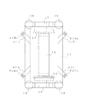
As shown in FIGS. 2 and 3, the
[0029]
As shown in FIGS. 4 to 6 (a) and 6 (b), the right end of the articulated
[0030]
The
[0031]
Four pillow springs 18 made of an elastic body such as an air spring, a rubber spring, and a coil spring are installed in the vicinity of the front and rear ends of the support portion 11 b of the
[0032]
A pair of left and
[0033]
The front and rear portions of the
[0034]
The
[0035]
On the other hand, the other end portions 14Ab, 14Bb, 14Cb, and 14Db (base end side) of the link members 14A to 14D are located at the center of the
[0036]
Each of the link members 14A to 14D has extension lines PA, PB, PC, PD extending from an axis that is a straight line connecting the front and rear end portions 14Aa, 14Ba, 14Ca, 14Da, 14Ab, 14Bb, 14Cb, 14Db in plan view. However, in the vicinity of the
[0037]
In addition, instead of the spherical bearing at the coupling portion between the end portions 14Aa to 14Da of the link members 14A to 14D and the
[0038]
In this way, the single-
[0039]
If comprised in this way, in the side view, the extension lines PA-PD of the axial line corresponding to the action line which connects the coupling position with respect to the
[0040]
In this case, since the
[0041]
The pair of
[0042]
Such a configuration is particularly advantageous in the case of the low-
[0043]
In addition, the
[0044]
As shown in FIGS. 9 and 10, when the single-
[0045]
Further, as shown in FIGS. 11 and 12, the base end portions of the left and right link members 14A to 14D, which are arranged in a substantially C shape in plan view and whose distal end portions are rotatably connected to the
[0046]
Specifically, the base ends of the left and
[0047]
In this way, the left and right translational movement capacity is increased, and the relative displacement in the vehicle body width direction generated between the
[0048]
Moreover, it is also possible to configure the front and rear link mechanisms using the torsion bar as shown in FIGS. 13 and 14 to prevent pitching.
[0049]
That is, as shown in FIGS. 13 and 14, among the
[0050]
In this way, when the front and
[0051]
In that case, the operation of the
[0052]
Further, as shown in FIG. 16, contrary to the case shown in FIGS. 13 and 14, the torsion bar may be provided so that the extension bar portion extends outward of the vehicle body. In this case, the
[0053]
As shown in FIGS. 17 and 18, a composite link member having a laminated rubber portion may be used instead of the link members 14A to 14D described above.
[0054]
That is, the front and rear portions of the
[0055]
Furthermore, the front and
[0056]
The
[0057]
In this way, the relative displacement in the vertical direction between the
[0058]
Furthermore, it is also possible to prevent the bogie from being pitched by using a two-hinge mechanism as shown in FIGS.
[0059]
That is, while the base end portion of the
[0060]
In this way, when the
[0061]
As another embodiment, a configuration in which the first hinge member is pivotally supported on the
[0062]
Although one embodiment of the single-axle truck according to the present invention has been described above, the present invention is not limited to a 100% low-floor type vehicle, and is a partially fixed floor type two-car train shown in FIG. It can also be applied to some articulated
[0063]
Needless to say, the present invention can be applied not only to a low-floor type tram but also to a general tram with a high floor position and a railway vehicle designed to reduce weight.
[0064]
Furthermore, in the above-described embodiment, a low floor type non-rotating axle member is used, but it is needless to say that a skewer shaft for a general vehicle can be used.
[0065]
Furthermore, in the above-described embodiment, the axle box guard system is adopted, but the present invention is not limited thereto, and other systems (for example, pedestal (Wing spring type, IS type, leaf spring type, link type, cone laminated rubber type, shaft beam type, cylindrical guide type, buffer rubber type) can also be applied.
[0066]
【The invention's effect】
The present invention is implemented as described above, and has the following effects.
[0067]
In the first aspect of the invention, the carriage frame is supported by the link members positioned forward and backward on either side of the left and right sides, and the extension line of the axis of the link member positioned forward and backward is the contact between the wheel and the rail in the side view. Since it is arranged so as to pass through the point, the driving force acting on the wheel is decomposed into a force that coincides with the axial direction of the link member, so that no pitching moment is generated. Therefore, pitching can be prevented.
[0068]
In addition, the left and right link members constituting the front or rear link mechanism are arranged in a substantially C shape in plan view, and the extension line of the axis of the link member is substantially on the central axis in the width direction of the vehicle body (substantially the vehicle The center pin in the width direction of the vehicle is crossed and the intersection is made to turn around the virtual turning center of the uniaxial carriage, so there is no need to provide a center pin for turning the carriage. Also, since the link member can be connected near the side beam of the carriage frame, the force can be transferred between the vehicle body and the carriage near the side beam, and the force transfer can be performed in the center of the width direction of the vehicle body. On the axisDoThis is more advantageous than the strength of the bogie frame. Further, with respect to the vehicle body, the force from the carriage is transmitted to the vicinity of the left and right side beams, which is advantageous in constructing the frame of the vehicle body. Further, when the center pin for turning the carriage is provided as in the prior art, the load is borne at one central position. However, as in the first aspect of the invention, the center pin is arranged in a substantially C shape in plan view. When the left and right link members are used in the front-rear direction, the load can be distributed and loaded at four places, which is advantageous in reducing the load load.
In addition, since the two front and rear link members of the front and rear link mechanisms are respectively connected by the torsion bar, the two front and rear link members are displaced in the vertical direction in opposite phases ( (Corresponding to pitching), the torsion bar is twisted and becomes resistant to the displacement, and the pitching can be restricted.
In the invention of
[0069]
Claim3If the left and right link members are connected to a portion of the bogie frame that is located below the center position of the left and right wheels, the bogie frame of the link member for towing the vehicle body The connecting point to the lower than that of the conventional cart can be reduced, and the pitching moment can be reduced.
[0070]
Claim4As described above, if one end portion or both end portions of each link member are coupled via an elastic member, or the link length of the link member can be expanded and contracted, the bogie frame as described above. In the configuration in which the front and rear portions are supported by the front and rear link mechanisms, the bogie frame easily moves up and down by elastic deformation of the elastic member or expansion and contraction of the link member.
[0074]
And claimsThe invention of 5A first hinge member whose base end is pivotally supported on the vehicle body or the carriage frame so as to be rotatable in the left-right direction, and a second hinge whose base end is pivotally supported on the carriage frame or the vehicle body so as to be rotatable in the vertical direction. When the member is coupled to the left and right and up and down via a cross-shaped member, the second or first hinge whose base end is pivotally supported by the cart frame when the cart frame is pitched Although the tip of the member is inclined, the movement is restricted by the first or second hinge member connected via the cross-shaped member, so that it is possible to prevent the inclination and prevent pitching after all. Become.
[Brief description of the drawings]
FIG. 1 is an explanatory view of a pitching moment that acts on a single-shaft bogie for a railway vehicle according to the present invention.
FIG. 2 is a side view showing a 100% low floor type single vehicle to which the single-axle carriage for railway vehicles according to the present invention is applied.
FIG. 3 is a side view showing a 100% low-floor two-car train articulated vehicle to which the railway vehicle single-shaft truck according to the present invention is applied.
FIG. 4 is a side view showing a schematic configuration of a single-shaft truck for a rail vehicle according to the present invention.
FIG. 5 is a plan view of the same.
FIG. 6A is a rear view of a uniaxial railcar for a railcar according to the present invention, and FIG. 6B is a rear view showing a link member omitted.
FIG. 7 is a plan view of an example in which the railway vehicle single-shaft truck according to the present invention is applied to a connecting portion of a vehicle.
FIG. 8 is a side view of the same.
FIG. 9 is an explanatory view of the movement of the link member according to the present invention.
FIG. 10 is an explanatory view of the movement of the link member according to the present invention.
FIG. 11 is a plan view of an embodiment in which a parallel link mechanism is applied in a single-axle carriage for a rail vehicle according to the present invention.
FIG. 12 is a side view of the same.
FIG. 13 is a plan view of an embodiment using a torsion bar.
FIG. 14 is a side view of the same.
FIGS. 15A to 15E are explanatory diagrams of movement of the torsion bar, respectively.
FIG. 16 is a plan view of another embodiment using a torsion bar.
FIG. 17 is a plan view of an embodiment using a composite link member having a laminated rubber portion.
FIG. 18 is a side view of the same.
FIG. 19 is a side view of an embodiment using a parallel link mechanism having two upper and lower stages.
FIG. 20 is a plan view of an embodiment using a two-hinge mechanism.
FIG. 21 is a perspective view of the main part.
FIG. 22 is a side view showing a partially low-floored two-car trained vehicle in which a single-shaft cart according to an embodiment of the present invention is applied to a coupled location.
[Explanation of symbols]
1 Single vehicle
1 'articulated vehicle
1 ”articulated vehicle
2 Floor
3 body
9 rails
10 1-axis cart
11 Bogie frame
11a The base of the bogie frame
11b Bogie frame support
12 Axle member
13 wheels
13a axle
14, 14 'link mechanism
14A-14D Link member
14Aa-14Da one end
14Ab-14Db The other end
15 Shaft box guard
15a Upper side of axle box guard member
16 axis box
17 shaft spring
18 Pillow spring
20 Bracket
40, 40A parallel link mechanism
41A, 41B Link member
42A-42D Link member
43A to 43D Bracket
51, 51 'Torsion bar
51a, 51a 'torsion bar base
51b, 51b 'extension bar
51c, 51c 'extension bar
52, 52 'mounting member
53, 53 'mounting member
61A-61D Composite link member
61 Aa to 61 Da Laminated rubber part
71 Two-stage parallel link mechanism
72,73 Link member
72A, 72B link
73A, 73B link
74 links
75 Front bracket
76 Rear bracket
81 First hinge member
82 Second hinge member
83 Cross member
83a Vertical shaft
83b Horizontal shaft
Claims (5)
前記前側および後側のリンク機構のうち、左側または右側の前後2つのリンク部材が、それぞれトーションバーで結合されていることを特徴とする鉄道車両用1軸台車。A wheel frame is supported by an axle or a component that replaces the axle, and a carriage frame that holds the axle or the component that replaces the axle is a single-shaft carriage for a railway vehicle that supports a vehicle body with four pillow springs, and the carriage frame The front and rear portions of the vehicle are connected to the vehicle body via front and rear link mechanisms, respectively, and the link mechanisms are substantially in plan view so that the distance in the width direction on the vehicle body side is wider than that on the cart frame side. The left and right link members are arranged so that the intersection of the extension lines of the axis in plan view is located on the center axis in the width direction of the vehicle body, and the intersection of the extension lines of the axis of the left and right link members is virtually The link member is configured to be turnable as a turning center, and the link member is configured such that, in a side view, an extension line of the axis passes through a contact point between the left and right wheels and the rail ,
A railcar single-axle carriage characterized in that, in the front and rear link mechanisms, the front and rear two link members on the left side or the right side are respectively connected by a torsion bar .
前記各リンク部材は、少なくとも一部に板層とゴム層とが交互に配置されてなる積層ゴム部を有する複合リンク部材であることを特徴とする鉄道車両用1軸台車。 A wheel frame is supported by an axle or a component that replaces the axle, and a carriage frame that holds the axle or the component that replaces the axle is a single-shaft carriage for a railway vehicle that supports a vehicle body with four pillow springs, and the carriage frame The front and rear portions of the vehicle are connected to the vehicle body via front and rear link mechanisms, respectively, and the link mechanisms are substantially in plan view so that the distance in the width direction on the vehicle body side is wider than that on the cart frame side. The left and right link members are arranged so that the intersection of the extension lines of the axis in plan view is located on the center axis in the width direction of the vehicle body, and the intersection of the extension lines of the axis of the left and right link members is virtually The link member is configured to be turnable as a turning center, and the link member is configured such that, in a side view, an extension line of the axis passes through a contact point between the left and right wheels and the rail,
Each of the link members is a composite link member having a laminated rubber portion in which plate layers and rubber layers are alternately arranged at least partially .
左右方向に回転可能に車体又は台車枠に基端部が軸支された第1のヒンジ部材と、上下方向に回転可能に台車枠又は車体に基端部が軸支された第2のヒンジ部材と、第1及び第2のヒンジ部材の先端部を、左右方向及び上下方向に回転可能に結合する十字形部材とを備えることを特徴とする鉄道車両用1軸台車。The wheel is supported by an axle or a component that replaces it, and the bogie frame that holds the axle or the component that replaces it is a uniaxial railcar for a railway vehicle that supports the vehicle body with four pillow springs,
A first hinge member whose base end is pivotally supported on a vehicle body or a carriage frame so as to be rotatable in the left-right direction, and a second hinge member whose base end is pivotally supported on the carriage frame or the vehicle body so as to be rotatable in a vertical direction. And a cross-shaped member that joins the tip ends of the first and second hinge members so as to be rotatable in the left-right direction and the up-down direction.
Priority Applications (1)
| Application Number | Priority Date | Filing Date | Title |
|---|---|---|---|
| JP2001034669A JP4656738B2 (en) | 2001-02-09 | 2001-02-09 | Single-axle truck for railway vehicles |
Applications Claiming Priority (1)
| Application Number | Priority Date | Filing Date | Title |
|---|---|---|---|
| JP2001034669A JP4656738B2 (en) | 2001-02-09 | 2001-02-09 | Single-axle truck for railway vehicles |
Publications (3)
| Publication Number | Publication Date |
|---|---|
| JP2002234435A JP2002234435A (en) | 2002-08-20 |
| JP2002234435A5 JP2002234435A5 (en) | 2008-03-21 |
| JP4656738B2 true JP4656738B2 (en) | 2011-03-23 |
Family
ID=18898227
Family Applications (1)
| Application Number | Title | Priority Date | Filing Date |
|---|---|---|---|
| JP2001034669A Expired - Fee Related JP4656738B2 (en) | 2001-02-09 | 2001-02-09 | Single-axle truck for railway vehicles |
Country Status (1)
| Country | Link |
|---|---|
| JP (1) | JP4656738B2 (en) |
Families Citing this family (3)
| Publication number | Priority date | Publication date | Assignee | Title |
|---|---|---|---|---|
| CN101844566B (en) * | 2010-06-04 | 2011-06-29 | 唐山轨道客车有限责任公司 | Power bogie for meter gauge |
| JP6281839B2 (en) * | 2013-12-04 | 2018-02-21 | 重樹 福田 | Railway vehicle running system |
| CN107554544A (en) * | 2017-10-16 | 2018-01-09 | 重庆中车长客轨道车辆有限公司 | A kind of straddle-type monorail train and its dual-pulling rod type single-axle bogie |
Citations (11)
| Publication number | Priority date | Publication date | Assignee | Title |
|---|---|---|---|---|
| JPS58112869A (en) * | 1981-12-28 | 1983-07-05 | 富士重工業株式会社 | Car for track |
| JPS63182968U (en) * | 1987-05-20 | 1988-11-25 | ||
| JPS63305072A (en) * | 1987-03-12 | 1988-12-13 | ウアゴン・ウニオン・ゲゼルシヤフト・ミト・ベシユレンクテル・ハフツング | Uniaxial running gear with run-idle wheel for rail car |
| JPH04243661A (en) * | 1991-01-25 | 1992-08-31 | Hitachi Ltd | Divided truck for magnetically-levitated articulated vehicle |
| JPH06270809A (en) * | 1993-03-18 | 1994-09-27 | Hitachi Ltd | Truck for rolling stock |
| JPH10250573A (en) * | 1997-03-14 | 1998-09-22 | Central Japan Railway Co | Car body supporting device for railway rolling stock |
| JP2002067942A (en) * | 2000-09-05 | 2002-03-08 | Sumitomo Kinzoku Technol Kk | Rolling stock body supporting mechanism for single axle bogie, bogie for railway rolling stock with same, and railway rolling stock with the bogie |
| JP2002211392A (en) * | 2001-01-12 | 2002-07-31 | Kawasaki Heavy Ind Ltd | Single axle bogie for rolling stock |
| JP2002220050A (en) * | 2001-01-24 | 2002-08-06 | Kawasaki Heavy Ind Ltd | Single axle bogie for rolling stock |
| JP2002234434A (en) * | 2001-02-09 | 2002-08-20 | Kawasaki Heavy Ind Ltd | Single axle bogie for rolling stock |
| JP2002234433A (en) * | 2001-02-08 | 2002-08-20 | Kawasaki Heavy Ind Ltd | Single axle bogie for coupling part in rolling stock |
-
2001
- 2001-02-09 JP JP2001034669A patent/JP4656738B2/en not_active Expired - Fee Related
Patent Citations (11)
| Publication number | Priority date | Publication date | Assignee | Title |
|---|---|---|---|---|
| JPS58112869A (en) * | 1981-12-28 | 1983-07-05 | 富士重工業株式会社 | Car for track |
| JPS63305072A (en) * | 1987-03-12 | 1988-12-13 | ウアゴン・ウニオン・ゲゼルシヤフト・ミト・ベシユレンクテル・ハフツング | Uniaxial running gear with run-idle wheel for rail car |
| JPS63182968U (en) * | 1987-05-20 | 1988-11-25 | ||
| JPH04243661A (en) * | 1991-01-25 | 1992-08-31 | Hitachi Ltd | Divided truck for magnetically-levitated articulated vehicle |
| JPH06270809A (en) * | 1993-03-18 | 1994-09-27 | Hitachi Ltd | Truck for rolling stock |
| JPH10250573A (en) * | 1997-03-14 | 1998-09-22 | Central Japan Railway Co | Car body supporting device for railway rolling stock |
| JP2002067942A (en) * | 2000-09-05 | 2002-03-08 | Sumitomo Kinzoku Technol Kk | Rolling stock body supporting mechanism for single axle bogie, bogie for railway rolling stock with same, and railway rolling stock with the bogie |
| JP2002211392A (en) * | 2001-01-12 | 2002-07-31 | Kawasaki Heavy Ind Ltd | Single axle bogie for rolling stock |
| JP2002220050A (en) * | 2001-01-24 | 2002-08-06 | Kawasaki Heavy Ind Ltd | Single axle bogie for rolling stock |
| JP2002234433A (en) * | 2001-02-08 | 2002-08-20 | Kawasaki Heavy Ind Ltd | Single axle bogie for coupling part in rolling stock |
| JP2002234434A (en) * | 2001-02-09 | 2002-08-20 | Kawasaki Heavy Ind Ltd | Single axle bogie for rolling stock |
Also Published As
| Publication number | Publication date |
|---|---|
| JP2002234435A (en) | 2002-08-20 |
Similar Documents
| Publication | Publication Date | Title |
|---|---|---|
| JP4262747B2 (en) | Large-capacity trains for passenger transport, especially rail-running trains with car bodies connected by joints | |
| US4485743A (en) | High efficiency semi-articulated railway power truck | |
| KR20060116168A (en) | Articulated train rake and car for making up such a rake | |
| JPH06504508A (en) | Traveling device for descending frame type rail vehicle | |
| US3547046A (en) | Railway locomotive truck with low traction point | |
| EP1741610B1 (en) | Low-deck articulated rail vehicle, particulary a tram | |
| RU2203818C2 (en) | Running part of rail vehicle bogie | |
| JPH0571428B2 (en) | ||
| JP3524500B2 (en) | Single-axle bogies for railway vehicles | |
| JP3524511B2 (en) | Single-axle bogies for railway vehicles | |
| JP4656738B2 (en) | Single-axle truck for railway vehicles | |
| JP2002220050A (en) | Single axle bogie for rolling stock | |
| US4221172A (en) | Articulated railway truck | |
| CN208181078U (en) | Bogie assembly and rail vehicle | |
| JP2000038132A (en) | Rolling stock truck | |
| RU2278040C2 (en) | Six-wheel bogie with self-aligning axles | |
| JP3604668B2 (en) | Single-axle bogies for railway vehicles | |
| JP2002211394A (en) | Bogie for rolling stock | |
| JP4142760B2 (en) | Railcar bogie | |
| JP2002234434A (en) | Single axle bogie for rolling stock | |
| JPH0321380B2 (en) | ||
| JP4656739B2 (en) | Single-axle truck for railway vehicles | |
| JP3667663B2 (en) | Single-axle truck for railway vehicles | |
| JP3679063B2 (en) | Single-axle truck for railway vehicles | |
| JP4618903B2 (en) | Single-axle truck for connecting railway vehicles |
Legal Events
| Date | Code | Title | Description |
|---|---|---|---|
| A521 | Written amendment |
Free format text: JAPANESE INTERMEDIATE CODE: A523 Effective date: 20080201 |
|
| A621 | Written request for application examination |
Free format text: JAPANESE INTERMEDIATE CODE: A621 Effective date: 20080201 |
|
| A977 | Report on retrieval |
Free format text: JAPANESE INTERMEDIATE CODE: A971007 Effective date: 20100924 |
|
| A131 | Notification of reasons for refusal |
Free format text: JAPANESE INTERMEDIATE CODE: A131 Effective date: 20100928 |
|
| A521 | Written amendment |
Free format text: JAPANESE INTERMEDIATE CODE: A523 Effective date: 20101124 |
|
| TRDD | Decision of grant or rejection written | ||
| A01 | Written decision to grant a patent or to grant a registration (utility model) |
Free format text: JAPANESE INTERMEDIATE CODE: A01 Effective date: 20101221 |
|
| A01 | Written decision to grant a patent or to grant a registration (utility model) |
Free format text: JAPANESE INTERMEDIATE CODE: A01 |
|
| A61 | First payment of annual fees (during grant procedure) |
Free format text: JAPANESE INTERMEDIATE CODE: A61 Effective date: 20101221 |
|
| FPAY | Renewal fee payment (event date is renewal date of database) |
Free format text: PAYMENT UNTIL: 20140107 Year of fee payment: 3 |
|
| R150 | Certificate of patent or registration of utility model |
Ref document number: 4656738 Country of ref document: JP Free format text: JAPANESE INTERMEDIATE CODE: R150 Free format text: JAPANESE INTERMEDIATE CODE: R150 |
|
| FPAY | Renewal fee payment (event date is renewal date of database) |
Free format text: PAYMENT UNTIL: 20150107 Year of fee payment: 4 |
|
| LAPS | Cancellation because of no payment of annual fees |