JP4656739B2 - Single-axle truck for railway vehicles - Google Patents
Single-axle truck for railway vehicles Download PDFInfo
- Publication number
- JP4656739B2 JP4656739B2 JP2001034670A JP2001034670A JP4656739B2 JP 4656739 B2 JP4656739 B2 JP 4656739B2 JP 2001034670 A JP2001034670 A JP 2001034670A JP 2001034670 A JP2001034670 A JP 2001034670A JP 4656739 B2 JP4656739 B2 JP 4656739B2
- Authority
- JP
- Japan
- Prior art keywords
- vehicle body
- axle
- carriage
- vehicle
- frame
- Prior art date
- Legal status (The legal status is an assumption and is not a legal conclusion. Google has not performed a legal analysis and makes no representation as to the accuracy of the status listed.)
- Expired - Fee Related
Links
Images


Description
【0001】
【発明の属する技術分野】
この発明は、鉄道車両用1軸台車、特に鉄道車両のうち低床式路面電車に適する1軸台車(台車枠に一つの車軸を備えた)に関する。
【0002】
【従来の技術】
近年、省エネルギー、低公害およびバリアフリーなどの特性を有することから、LRV(Light Rail Vehicle)と称される路面電車が再評価され、欧米をはじめ各都市で導入が進んでいる。この種の路面電車は、車両重量が軽く、軌道上を走行する台車部分を1軸台車で構成することができる。1軸台車は、周知のように、台車枠には左右に車輪を備えた車軸を一つしか設けていないことから、台車がピッチングしやすいという欠点がある。
【0003】
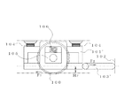
すなわち、図14に示すように、車輪100に駆動力F1(ブレーキ力)が水平方向に作用すると、前記車輪100の中心位置(軸芯位置)よりも上方に位置している、台車枠101の部分と車体102とを結合する水平なリンク部材103に水平方向の車体牽引力F2が発生し、この2つの力F1,F2の間の距離H1(リンク部材101の台車枠101への連結点の高さ)により、台車にピッチングモーメントM1(=F1×H1=F2×H1)が作用する。このモーメントM1は、4本の枕ばね104の反力F3,F4によるモーメントM2(=F3・L1−F4・L1)で打ち消されることになるが、枕ばね104間の距離2L1が短いために、傾き角を小さく抑制するには、枕ばね104の剛性を高める必要がある。一方、枕ばね104の剛性を高めると、上下方向の振動に対して、良好な乗り心地を確保する上で不利である。なお、前記枕ばね104の反力F3,F4の和は、レール反力Wに等しくなる。105は軸箱守方式で支持されている軸箱、106は軸ばねである。
【0004】
そこで、たとえば車両の床面が軌道上からかなり高い位置(800mm〜1100mm)に位置している高床式の1軸台車では、台車枠の前後に上下一対のラジアスロッドを配置して、これらの上下1対のラジアスロッドの踏ん張りによってピッチングを防止するようにした、DSB(DanskeStadsBanen)と称される構造の台車が提案されている。
【0005】
その他の先行技術として、特開平10−250573号公報に記載の1軸台車がある。この台車は、1本の輪軸の両端を台車枠に支持し、この台車枠と車体との間に複数個の枕ばねを介して車体を支持し、前記台車枠と前記車体とを前後方向の相対的な移動を規制する牽引機構により連結した構造からなっている。
【0006】
また、特許第2788047号掲載公報に記載の台車がある。この台車は台車枠に対し前後2つの車軸の中央部が軸受手段を介してハの字形リンク部材により支持されるとともに、スリ板を介して台車の旋回時に車軸の前後方向および左右方向の摺動が可能なように構成されている。
【0007】
【発明が解決しようとする課題】
しかしながら、上記した従来のDSB台車および上記の2件の公報に記載の台車では、次のような点で不都合がある。
【0008】
すなわち、車両の床面の高さが軌道から300mm程度しかない低床式の路面電車に適用しようとすると、台車が配置される位置の床面をかなり高くする必要があり、床面に凹凸が生じる。いいかえれば、100%低床式の路面電車には適用することができない。
【0009】
また、2両編成の車両において車両の連結(連接)部間に配置される連接台車として適用することも、構造的に困難である。
【0010】
さらに、特許第2788047号掲載公報に記載の台車は二軸台車であり、また各車軸は左右の車輪を直接結合して回転するいわゆる串軸であるから、1軸台車を対象とし、左右の車輪を別々に支持するいわゆる独立車輪を用いる本発明の台車には適用することができない。
【0011】
本発明は上述の点に鑑みなされたもので、構造が簡単で軽量で、一軸でピッチングを防止することができ、乗り心地が良好で、低床式の路面電車にも適用可能である鉄道車両用1軸台車を提供することを目的としている。
【0012】
【課題を解決するための手段】
請求項1の発明は、車輪が車軸又はそれに代わる構成部材に回転可能に支持されており、この車軸又はそれに代わる構成部材を保持する台車枠が4つの枕ばねにて車体に支持されるともに、前記台車枠がリンク機構を介して車体に結合されている鉄道車両用1軸台車であって、前記リンク機構が、前記台車枠側に比べて車体側の幅方向の間隔が広くなるように平面視略ハの字状に配置され、かつ平面視における軸線の延長線上の交点が車体の幅方向の中心軸線上に位置する左右のリンク部材を備え、前記左右のリンク部材の軸線の延長線上の交点を仮想旋回中心として旋回可能に構成され、前記台車枠が、前記左右の車輪の中心位置よりも下方に位置する部分を有し、その部分に前記左右のリンク部材が連結され、前記車体とリンク部材との間又はリンク部材と台車枠との間に、平行リンク機構が設けられていることを特徴とする。ここで、「前記台車枠が、前記左右の車輪の中心位置よりも下方に位置する部分を有し、その部分に前記左右のリンク部材が連結されている」とは、前記左右のリンク部材の台車枠への連結点が、前記左右の車輪の中心位置よりも下方に位置している、ということを意味する。
【0013】
請求項1の発明によれば、前記台車枠が、前記左右の車輪の中心位置よりも下方に位置する部分を有し、その部分に前記左右のリンク部材が連結されるようにすることで、前記左右のリンク部材の台車枠への連結点が前記左右の車輪の中心位置よりも下方に位置するようにしているので、従来構造に比べて台車枠への連結点がかなり低い位置となりピッチング防止の点において有利となる。すなわち、図1に示すように、車体牽引のためのリンク部材103’の台車枠101’への連結点の位置が、図14に示す従来の台車に比べて低くなり(H2<H1)、ピッチングモーメントM3(=F1×H2=F2×H2)を小さくすることができる。例えば、連結点の高さH2を、従来の高さH1の1/4程度にすれば、ピッチングモーメントも1/4程度となる。
【0014】
また、平面視略ハの字状に配置された一対のリンク部材は、平面視でリンク部材の軸線の延長線がほぼ車体の幅方向の中心軸線上(ほぼ車両の幅方向の中心)で交差するから、この交点を仮想旋回中心として1軸台車が旋回する。特に、先頭に位置する台車の場合には前記交点が車軸中心より後ろの位置に生じるようにすれば、車軸の車両進行方向後方位置を中心に旋回することになり、曲線通過性能が向上するようにできる。後方に位置する台車の場合には、車体を含むプル・プッシュの影響によって、進行方向とは逆の側が旋回中心となってもほとんど影響を受けない。
【0015】
この構成により、台車旋回用の中心ピンを設ける必要がなくなり、台車枠の側はり付近にリンク部材の連結箇所を設けることができるので、車体と台車との力の受け渡しを車体の幅方向の中心軸線上ではなく、側はり付近で行なうことができるようになり、台車枠および車体台枠の強度面から有利となる。また、車体についても、台車からの力が左右の側はり付近に伝達されることになるので、車体の台枠を構成する上で有利である。
【0016】
さらに、台車旋回用の中心ピンを設け、その中心ピンでもって中央の1カ所で荷重を負担する場合に比べて、平面視略ハの字状に配置した一対のリンク部材を用いる場合には、荷重の負担を2カ所に分散することができ、負担の軽減が図れる。
それに加えて、台車枠と車体との間に生ずる車体幅方向の相対変位が、平行リンク機構によって、吸収緩和され、スムーズな走行が実現されるようになる。
【0017】
上記の台車構造を採用することにより、請求項2に記載のように、前記左右のリンク部材の台車枠への連結点が、レール踏面から100mm〜300mmの高さに位置するようにすることができる。
【0018】
請求項2の発明によれば、左右のリンク部材の台車枠への連結点を、レール踏面から100mm〜300mmの高さに位置させ、低床化が図れるだけでなく、ピッチング防止の点においても有利となる。
【0019】
また、請求項3の発明は、車輪が車軸又はそれに代わる構成部材に回転可能に支持されており、この車軸又はそれに代わる構成部材を保持する台車枠が4つの枕ばねにて車体に支持されるともに、前記台車枠がリンク機構を介して車体に結合されている鉄道車両用1軸台車であって、前記リンク機構が、前記台車枠側に比べて車体側の幅方向の間隔が広くなるように平面視略ハの字状に配置され、かつ平面視における軸線の延長線上の交点が車体の幅方向の中心軸線上に位置する左右のリンク部材を備え、前記左右のリンク部材の軸線の延長線上の交点を仮想旋回中心として旋回可能に構成され、前記リンク部材は、側面視において、その軸線の延長線が、左右の車輪とレールとの接触点を通過するように構成され、前記車体とリンク部材との間又はリンク部材と台車枠との間に、平行リンク機構が設けられていることを特徴とする。
【0020】
請求項3の発明によれば、側面視においてリンク部材の軸線(車体に対する結合位置と台車枠に対する結合位置とを結ぶ作用線の方向に一致)の延長線が、車輪の踏面付近で台車の中心線と交差するように傾斜させているから、レール上の車輪の踏面に前後方向の接線力(具体的には駆動力や制動力)が作用しても、リンク部材の台車枠への取付高さに関わらず、台車をピッチングさせる力は作用せず、ピッチングが確実に防止される。
【0021】
請求項4に記載のように、前記リンク部材は、一端部が球面軸受け、ユニバーサルジョイントあるいは弾性体を介して台車枠に結合され、他端部が前記車体に垂直軸回り又は垂直方向の上端側が下端側に比べて車体端部側へ傾斜した傾斜軸回りに回転可能に軸支されていることが望ましい。
【0022】
請求項4の発明によれば、リンク部材と台車枠あるいは車体との結合部において無理な力が作用するのが回避される。
【0025】
【発明の実施の形態】
以下、この発明の実施の形態を図面に沿って説明する。
【0026】
図2は本発明の実施例に係る1軸台車を適用した100%低床式単一車両を示す側面図、図3は本発明の実施例に係る1軸台車を適用した100%低床式2両編成の連接車両を示す側面図である。
【0027】
図2および図3に示すように、本発明に係る各路面電車である単一車両1および連接車両1’は、床面2が軌道としてのレール9から300mm若しくは330mmの高さに位置する100%低床式に構成され、台車は全て1軸台車10からなり、床面2は1軸台車10の位置で幅がやや狭くなっているが、車体3の全長にわたり平坦な床面とされている。
【0028】
図4〜図6(a)(b)に示すように、連接車両1の右端および単一車両1の左端および連接車両1’の左端の1軸台車10は、同一の構成で、平面視矩形状の台車枠11、車軸又はそれに代わる構成部材としてのU字形状の非回転式の車軸部材12、車輪13およびリンク機構14を備え、左右の車輪13は車軸13aに取り付けられ、この車軸部材12を、軸箱16および軸ばね17を介して、台車枠11が保持するようになっている。
【0029】
前記台車枠11は、平面視で幅方向に長い矩形状の基部11aと、その基部11aの左右両側部に設けられ中央位置にほぼロの字形状の軸箱守り部材15を両側から支持する、ほぼL字形状の支持部11bとにより形成されている。前記軸箱守り部材15内には、車輪13の車軸13aに支持される軸箱16が上下方向に移動可能に設けられ、軸箱守り部材15の上辺部15aと軸箱16との間に、1次系サスペンションを構成する積層ゴムや圧縮スプリングなどの弾性体からなる軸ばね17が介設されている。
【0030】
前記台車枠11の支持部11bの前後端部付近には、空気ばね、ゴムばね、コイルばねなどの弾性体からなる4つの枕ばね18が設置され、この4つの枕ばね18にて車体3を台車枠に支持させるようにして、2次系サスペンションを構成している。
【0031】
左右の一対の車輪13が後方より見て上向きに凹状の非回転式の車軸部材12の両側に、軸受(図示せず)を介して左右独立して回転可能に支持されており(図6(b)参照)、このように構成される車輪13の車軸13aは、左右の軸箱16に支持されている。
【0032】
前記台車枠11は、リンク機構14を介して車体3に結合されているが、このリンク機構14は、前記台車枠11側に比べて車体3側の幅方向の間隔が広くなるように平面視略ハの字状に配置された一対のリンク部材14A,14Bを備えている。このリンク部材14A,14Bは、一端部14Aa,14Ba(先端側)が台車枠11に球面軸受(図示せず)により全方向に揺動自在に結合されている。
【0033】
また、前記台車枠11全体が、前記左右の車輪13の中心位置(軸芯位置)よりも下方に位置している。そして、前記台車枠11の後側部分に前記左右のリンク部材14A,14Bの一端部14Aa,14Baを連結し、前記左右のリンク部材14A,14Bの台車枠11への連結点が、前記左右の車輪13の回転中心位置よりも下方に位置するようにしている。このような構成により、ピッチングモーメントが小さくなり(図1参照)、ピッチングの防止の点で有利な構造となっている。具体的には、左右のリンク部材14A,14Bの台車枠11への連結点が、レール踏面から100mm〜300mmの高さに位置するようにされる。なお、本発明においては、前記台車枠11の基部11aが前記左右の車輪13の中心位置(軸芯位置)よりも下方に位置するようにしているが、そのように台車枠11の基部11aを必ずしも位置させる構成とする必要はなく、台車枠全体が前記左右の車輪の中心位置よりも下方に位置するようにしてもよいし、台車枠が、前記左右の車輪の中心位置よりも下方に位置する他の部分を有し、その他の部分に前記左右のリンク部材14A,14Bの一端部14Aa,14Baが連結されるようにしてもよい。
【0034】
一方、リンク部材14A,14Bの他端部14Ab,14Bb(基端側)は車体3に対し、ブラケット20を介して、垂直方向の上端側が下端側に比べて車軸部材中心側へ傾斜した傾斜軸回りに(または垂直軸回りに)回転可能に軸支(連結)されている。また、リンク部材14A,14Bの他端部14Ab,14Bbは車体3に軸支されているが、一端部14Aa,14Baよりも上方に位置し、かつ一端部14Aa,14Baよりも車両外方側に位置するように傾斜するように配設されている。そして、各リンク部材14A,14Bは、側面視において、リンク部材14A,14Bの軸線の延長線PA,PBが車輪13の踏面とレール9との接触点を通過するように構成されている(図4参照)。
【0035】
また、各リンク部材14A,14Bは、平面視において前後の両端部14Aa,14Ab,14Ba,14Bbを結ぶ直線である軸線を延ばした延長線PA,PBが、車軸部材12の近傍で、車体幅方向の中心位置を前後方向に通過する中心軸線CLと交差して、交点Oになる(図5参照)。
【0036】
なお、前記リンク部材14A,14Bの一端部14Aa,14Baと台車枠11との結合部分における球面軸受に代えて、ゴムなどの弾性体、又はユニバーサルジョイントを用いて全方向の揺動を許容するように連結することもできるのはいうまでもない。
【0037】
このようにして1軸台車10が構成されるが、単一車両1の右端および連接車両1’の右端の1軸台車10’は、前記1軸台車10の各構成部材と前後方向が対称に配置されるだけで、基本的に構成は共通している。また、連接車両1’の連接箇所に配置される1軸台車10”は、1軸台車10と共通のものを使用することができる。図7〜図9に示すように、一方の車体3’から他方の台車側に、先端に半球面状の受け部21aを有するアーム部21が延ばされる一方、他方の台車の車体3”から前記一方の台車側に、前記受け部21aに揺動可能に係合する係合凸部22aを有する別のアーム部22が延ばされ、前記受け部21aに係合凸部22aが上側から係合することで、連接部分が1つの1軸台車10”によって支持されるようになっている。なお、前記受け部21aと係合凸部22aとは、両アーム部21,22が分離しないように連接ピンにて結合されている。
【0038】
このように構成すれば、1軸台車10は車軸部材12に一対の車輪13がそれぞれ回転自在に支持され、また軸箱守り部材15に対し軸箱16が上下方向に摺動可能に支持され、軸箱16と軸箱守り部材15との間に設けられた軸ばね17により1次系のサスペンションが構成される。また、台車枠11は、前述したリンク機構14を介して車体3に結合され、この状態で台車枠11は球面軸受(図示せず)を支点として上下方向に揺動可能に支持され、台車枠11と車体3との枕ばね18により2次系のサスペンションが構成される。
【0039】
このように軸ばね17による1次系のサスペンションと、枕ばね18による2次系のサスペンションとの2つ系統のサスペンションで、車体3は、上下に揺動自在に支持されるために、乗り心地が良好である。
【0040】
また、1軸台車10が、例えば左旋回した場合には、車軸部材12の近傍に位置する交点Oを仮想旋回中心として車軸13aおよび台車枠11等が一体的に旋回する。このとき、リンク部材14A,14Bは、図10に示す状態から図11に示す状態に変位するとともに、枕ばね18が変形する。このようにして、曲線状のレール9に沿って1軸台車10が旋回し、レール9の直線部に進入すると、元の状態に旋回して戻る。
【0041】
しかも、リンク部材14A,14Bの車体3に対する結合位置と台車枠11に対する結合位置とを結ぶ作用線に一致する軸線の延長線PA,PBが、側面視において、車輪13とレール9との接触点を通過するように傾斜しているから、レール9上の車輪13の踏面に前後方向の接線力F1(具体的には駆動力や制動力)が作用しても、台車10をピッチングさせるピッチングモーメントは発生しない。すなわち、接線力F1は、リンク部材14A,14Bの軸線の延長線PA,PBの方向の力F5と鉛直方向の力F6に分けることができる。このうち、力F5の作用方向は、リンク部材14A,14Bの軸線の方向と一致しているので、台車10をピッチングさせるピッチングモーメントは生じない。また、力F6は車軸部材12の中心を通過する鉛直方向の力であり、枕ばね18に均等に分担されるので、やはり台車10をピッチングさせるピッチングモーメントは生じない。
【0042】
一方、平面視略ハの字状に配置された一対のリンク部材14A,14Bは、平面視でリンク部材14A,14Bの軸線の延長線PA,PBがほぼ車体3の幅方向の中心軸線CL上(ほぼ車両の幅方向の中央位置)で交差するから、この交点Oを1軸台車10の仮想旋回中心として旋回する。この構成により、台車10には旋回用の中心ピンを設ける必要がなく、台車枠11の側部付近にリンク部材14A,14Bとの連結箇所を設けることができる。
【0043】
このような構成とすることは、上記した低床式路面電車1,1’の場合には特に有利である。これは、車体3と台車10との力の受け渡しを車体3の幅方向の中心軸線CL上で行なうよりも、台車枠11の側部付近で行なう方が台車枠11の強度面から有利である。車体3の構成においても、低床式路面電車では車体3の側部(側はり)に強度を持たす構造でないと低床化に不利であり、台車からの力の伝達が車体中央ではなく、車体3の両側部の側はり付近に伝達されることが有利であるからである。また、平面視略ハの字状に配置した左右のリンク部材14A,14Bを用いたことにより荷重を2カ所に分散することができるので、旋回用の中心ピンを設けて中央の1カ所で荷重を負担する場合に比べて、台車枠11および車体台枠の荷重負担を軽減することができる。
【0044】
さらに、側面視において、リンク部材14A,14Bを、その軸線が傾斜せずほぼ水平方向に延びるように配置してもよく、その場合には、車輪13の踏面に前後方向の接線力(具体的には駆動力や制動力)が作用しても、リンク部材14A,14Bの台車枠3への取付位置のレール9からの高さH2が小さければ、ピッチングにより発生するピッチングモーメントも小さくなるため(図1参照)、わずかに枕ばね荷重などが変化するだけとなり、車軸部材12および車輪13が、車体3に対して相対的に大きなピッチング変位を起こすことがない。
【0045】
図12に示すように、平面視略ハの形状に配置された左右のリンク部材14Ab,14Bbの基端部を、平行リンク機構40を介して車体3に連結し、左右の並進運動能力を増加させるようにすることもできる。
【0046】
具体的には、平面視略ハの字形状に配置された左右のリンク部材14A,14Bの基端部14Ab,14Bbが、左右方向に延びるリンク部材41によって鉛直軸回りに回転可能に連結されるとともに、別のリンク部材42A,42Bの先端部に鉛直軸回りに回転可能に連結されている。リンク部材42A,42Bの基端部は、ブラケット43を介して、車体3に鉛直軸回りに回転可能に連結されている。この場合、平行リンク機構40(リンク部材41,42A,42B)は、車体3側に設けているが、台車枠11側に設けるようにしてもよい。
【0047】
図13に示す部分低床式の2両編成路面電車である連接車両1”にも適用することができる。この場合、連接車両1”は、車両1”の前部又は後部(端部)の床面2が他の部分に比べて高くされているため、連接部の台車10”を除いて上記路面電車1,1’に限らず、左右の車輪間を回転式の車軸(部材)で連結した従来の一般的な台車(図示せず)を使用することができる。
【0048】
以上に本発明の1軸台車の実施例を示したが、本発明は低床式路面電車に限らず、床面の位置が高い一般的な路面電車や軽量化を図った鉄道車両に適用できることはいうまでもない。
【0049】
前記実施の形態においては、低床式の非回転の車軸部材(車軸又はそれに代わる構成部材)を用いているが、本発明はそれに限定されるものではなく、一般車両用の串軸などを用いることができるのはもちろんである。
【0050】
また、前記実施の形態においては、軸箱守方式を採用しているが、本発明はそれに限定されるものではなく、いずれの軸箱の支持方式(ペデスタル・ウイングばね式、IS式、板ばね式、リンク式、円錐積層ゴム式、軸はり式、円筒案内式、緩衝ゴム式など)のものにも適用することができる。
【0051】
【発明の効果】
この発明は、以上に説明したように実施され、以下に述べるような効果を奏する。
【0052】
請求項1の発明は、台車枠が、前記左右の車輪の中心位置よりも下方に位置する部分を有し、その部分に前記左右のリンク部材が連結されているようにしているので、ピッチングモーメントが小さくなり、ピッチング防止の点において有利である。
【0053】
平面視略ハの字状に配置した一対のリンク部材を介して台車枠を車体に連結するようにしているので、それらの軸線の延長線の交点を1軸台車の仮想旋回中心として旋回することができ、特に、その交点が車軸の幅方向のほぼ中心位置にあるから、車軸(車軸部材を含む)の幅方向の中間位置を中心に旋回することになり、曲線路での台車の旋回が安定する。
【0054】
また、台車旋回用の中心ピンを設ける必要がなく、台車枠の側はり付近にリンク部材の連結箇所を設けることができるので、車体と台車との力の受け渡しを台車枠の側はり付近で行なうことができ、特に低床式路面電車の場合には、台車枠の強度面から有利である。また、車体についても、台車からの力が左右の側はり付近に伝達されることになるので、車体の台枠を構成する上で有利である。
【0055】
さらに、台車旋回用の中心ピンを設ける場合は台車の中央の1カ所で荷重を負担する必要があるのに対して、請求項1の発明は、平面視略ハの字状に配置した一対のリンク部材を用いているので、荷重を2カ所に分散して負担することができ、荷重負担の軽減の上で有利である。また、低床式の路面電車等の車両にも適用することができ、しかも構造が簡単で軽量であり、一軸であってもピッチングを防止することができ、乗り心地が良好になる。
それに加えて、前記車体とリンク部材との間、又はリンク部材と台車枠との間に、平行リンク機構を設けているので、平行リンク機構によって、台車枠の車体幅方向の動きを吸収緩和でき、スムーズな走行を実現することができる。
【0056】
請求項2に記載のように、リンク部材の台車枠への連結点を、レール踏面から100mm〜300mmの高さに位置させれば、台車をピッチングさせるピッチングモーメントが小さくなり、ピッチング防止の効果を得て、低床化を図ることができる。
【0057】
請求項3の発明は、リンク部材の軸線の延長線が、側面視において、車輪とレールとの接触点を通過するようにしているので、レール上の車輪の踏面に前後方向の接線力(具体的には力行や制動力)が作用しても、リンク部材の台車枠への取付高さに関わらず、台車をピッチングさせるピッチングモーメントは発生せず、したがって1軸台車を備えているにもかかわらず、ピッチングを確実に防止することができる。
【0058】
請求項4に記載のように、前記リンク部材は、一端部を球面軸受け等を介して台車枠に結合し、他端部を前記車体に垂直軸回り又は傾斜軸回りに回転可能に軸支するようにすれば、リンク部材と台車枠あるいは車体との結合部において無理な力が作用するのを回避することができる。
【図面の簡単な説明】
【図1】本発明に係る鉄道車両用1軸台車に作用するピッチングモーメントの説明図である。
【図2】本発明に係る鉄道車両用1軸台車を適用した100%低床式単一車両を示す側面図である。
【図3】本発明に係る鉄道車両用1軸台車を適用した100%低床式2両編成の連接車両を示す側面図である。
【図4】本発明に係る鉄道車両用1軸台車の概略構成を示す側面図である。
【図5】同平面図である。
【図6】(a)は本発明に係る鉄道車両用1軸台車の背面図、(b)はリンク部材を省略して示す背面図である。
【図7】本発明に係る鉄道車両用1軸台車を車両の連接部分に適用した例の平面図である。
【図8】同側面図である。
【図9】同背面図である。
【図10】本発明に係るリンク部材の動きの説明図である。
【図11】本発明に係るリンク部材の動きの説明図である。
【図12】本発明に係る鉄道車両用1軸台車において平行リンク機構を適用した実施の形態の平面図である。
【図13】本発明の実施例に係る1軸台車を連接個所に適用した部分低床式2両編成の連接車両を示す側面図である。
【図14】従来の鉄道車両用1軸台車に作用するピッチングモーメントの説明図である。
【符号の説明】
1 単一車両
1’ 連接車両
1” 連接車両
2 床面
3 車体
9 レール
10 1軸台車
11 台車枠
11a 台車枠の基部
11b 台車枠の支持部
12 非回転式車軸部材
13 車輪
13a 車軸
14 リンク機構
14A リンク部材
14Aa 一端部
14Ab 他端部
14B リンク部材
14Ba 一端部
14Bb 他端部
15 軸箱守り部材
16 軸箱
17 軸ばね
18 枕ばね
20 ブラケット
40 平行リンク機構[0001]
BACKGROUND OF THE INVENTION
The present invention relates to a single-shaft carriage for a railway vehicle, particularly a railway.vehicleRelates to a single-axis bogie suitable for a low-floor type tram (with one axle on the bogie frame).
[0002]
[Prior art]
In recent years, streetcars called LRVs (Light Rail Vehicles) have been re-evaluated due to their characteristics such as energy saving, low pollution, and barrier-free, and are being introduced in various cities including Europe and America. This type of tramway is light in vehicle weight, and the cart portion that travels on the track can be constituted by a single-axis cart. As is well known, the single-shaft carriage has a drawback that the carriage is easy to pitch because the carriage frame has only one axle with wheels on the left and right.
[0003]
That is, as shown in FIG. 14, when the driving force F1 (braking force) acts on the
[0004]
Thus, for example, in a stilt type single-shaft vehicle in which the floor surface of the vehicle is located at a considerably high position (800 mm to 1100 mm) from the track, a pair of upper and lower radius rods are arranged before and after the bogie frame, A cart with a structure called DSB (DanskeStadsBanen), which prevents pitching by straddling a pair of radius rods, has been proposed.
[0005]
As another prior art, there is a single-shaft cart described in JP-A-10-250573. The bogie supports both ends of a single axle on a bogie frame, supports the vehicle body via a plurality of pillow springs between the bogie frame and the vehicle body, and supports the bogie frame and the vehicle body in the front-rear direction. It consists of a structure connected by a traction mechanism that regulates relative movement.
[0006]
Moreover, there is a carriage described in Japanese Patent No. 2788047. In this carriage, the center part of the two front and rear axles is supported by a C-shaped link member via bearing means with respect to the carriage frame, and the axle slides in the front-rear direction and the left-right direction when the carriage is turned through a slot plate. Is configured to be possible.
[0007]
[Problems to be solved by the invention]
However, the conventional DSB cart and the carts described in the above two publications have the following disadvantages.
[0008]
That is, if it is intended to be applied to a low-floor type tram where the height of the floor of the vehicle is only about 300 mm from the track, it is necessary to make the floor at the position where the carriage is located considerably high, and the floor is uneven. Arise. In other words, it cannot be applied to a 100% low-floor tramway.
[0009]
In addition, it is structurally difficult to apply as a connecting cart disposed between connecting (connecting) portions of a vehicle in a two-car train.
[0010]
Further, the cart described in Japanese Patent No. 2788047 is a biaxial cart, and each axle is a so-called skewer shaft that rotates by directly coupling the left and right wheels. It cannot be applied to the cart of the present invention using so-called independent wheels that support the two separately.
[0011]
The present invention has been made in view of the above points, and has a simple structure, is lightweight, can prevent pitching on one axis, has a good ride comfort, and can be applied to a low-floor type tram. The purpose is to provide a single-axle vehicle.
[0012]
[Means for Solving the Problems]
In the first aspect of the invention, the wheel is rotatably supported by the axle or a constituent member that replaces the axle, and the carriage frame that holds the axle or the constituent member that replaces the axle is supported on the vehicle body by four pillow springs. A uniaxial truck for a railway vehicle in which the bogie frame is coupled to a vehicle body via a link mechanism, and the link mechanism is flat so that the interval in the width direction on the vehicle body side is wider than the bogie frame side. The left and right link members are arranged in a substantially C-shape and have an intersection on the extension line of the axis in plan view located on the center axis line in the width direction of the vehicle body, on the extension line of the axis line of the left and right link members The vehicle frame is configured to be turnable with an intersection as a virtual turning center, and the bogie frame has a portion located below the center position of the left and right wheels, and the left and right link members are connected to that portion.A parallel link mechanism is provided between the vehicle body and the link member or between the link member and the carriage frame.. Here, “the bogie frame has a portion located below the center position of the left and right wheels, and the left and right link members are connected to that portion” means that the left and right link members are It means that the connection point to the carriage frame is located below the center position of the left and right wheels.
[0013]
According to the invention of
[0014]
In addition, in the pair of link members arranged in a substantially C shape in plan view, the extension line of the axis of the link member intersects on the center axis in the width direction of the vehicle body (approximately the center in the width direction of the vehicle) in plan view. Therefore, the single-shaft carriage turns with this intersection as the virtual turning center. In particular, in the case of the bogie located at the head, if the intersection occurs at a position behind the axle center, the vehicle will turn around the rear position in the vehicle traveling direction of the axle so that the curve passing performance is improved. Can be. In the case of a carriage located at the rear, it is hardly affected even if the side opposite to the traveling direction becomes the turning center due to the influence of the pull push including the vehicle body.
[0015]
With this configuration, there is no need to provide a center pin for turning the carriage, and a link member connecting portion can be provided near the side beam of the carriage frame, so that the force transfer between the body and the carriage can be centered in the width direction of the body. This can be performed not on the axis but near the side beam, which is advantageous in terms of the strength of the carriage frame and the vehicle body frame. Further, with respect to the vehicle body, the force from the carriage is transmitted to the vicinity of the left and right side beams, which is advantageous in constructing the frame of the vehicle body.
[0016]
Furthermore, in the case of using a pair of link members arranged in a substantially C shape in plan view, compared to a case where a central pin for turning the carriage is provided and a load is borne by the central pin at one central location, The load burden can be distributed to two locations, reducing the burden.
In addition, the relative displacement in the vehicle body width direction that occurs between the carriage frame and the vehicle body is absorbed and relaxed by the parallel link mechanism, and smooth running is realized.
[0017]
By adopting the above-described carriage structure, as described in
[0018]
According to the invention of
[0019]
According to a third aspect of the present invention, the wheel is rotatably supported by the axle or a constituent member that replaces the axle, and the carriage frame that holds the axle or the constituent member that replaces the axle is supported by the vehicle body by four pillow springs. In both cases, the bogie frame is a single-shaft bogie for a railway vehicle that is coupled to the vehicle body via a link mechanism, and the link mechanism has a wider interval in the width direction on the vehicle body side than the bogie frame side. The left and right link members are arranged in a substantially C shape in plan view and the intersection of the extension lines of the axis in plan view is located on the center axis in the width direction of the vehicle body. The link member is configured to be able to turn with an intersection on a line as a virtual turning center, and the link member is configured so that an extension line of the axis passes through a contact point between the left and right wheels and the rail in a side view,A parallel link mechanism is provided between the vehicle body and the link member or between the link member and the carriage frame.To do.
[0020]
According to the invention of
[0021]
According to a fourth aspect of the present invention, one end of the link member is coupled to the carriage frame via a spherical bearing, a universal joint or an elastic body, and the other end of the link member has a vertical axis or a vertical upper end on the vehicle body. It is desirable that the shaft is supported so as to be rotatable around an inclination axis inclined toward the vehicle body end side compared to the lower end side.
[0022]
According to the invention of
[0025]
DETAILED DESCRIPTION OF THE INVENTION
Embodiments of the present invention will be described below with reference to the drawings.
[0026]
FIG. 2 is a side view showing a 100% low floor type single vehicle to which a single-shaft truck according to an embodiment of the present invention is applied. FIG. 3 is a 100% low floor type to which a single-shaft truck according to an embodiment of the present invention is applied. It is a side view showing an articulated vehicle of two-car train.
[0027]
As shown in FIGS. 2 and 3, the
[0028]
4 to 6 (a) and 6 (b), the right end of the articulated
[0029]
The
[0030]
Four pillow springs 18 made of an elastic body such as an air spring, a rubber spring, and a coil spring are installed near the front and rear ends of the support portion 11b of the
[0031]
A pair of left and
[0032]
The
[0033]
The
[0034]
On the other hand, the other end portions 14Ab, 14Bb (base end side) of the
[0035]
Further, each
[0036]
It should be noted that instead of the spherical bearing at the coupling portion between the one end portions 14Aa and 14Ba of the
[0037]
In this way, the single-
[0038]
If comprised in this way, as for the single-shaft trolley |
[0039]
In this way, the
[0040]
Further, when the single-
[0041]
Moreover, the extension lines PA and PB of the axial line that coincides with the action line connecting the coupling position of the
[0042]
On the other hand, in the pair of
[0043]
Such a configuration is particularly advantageous in the case of the low-
[0044]
Further, in the side view, the
[0045]
As shown in FIG. 12, the base end portions of the left and right link members 14Ab and 14Bb arranged in a substantially C shape in plan view are connected to the
[0046]
Specifically, the base end portions 14Ab and 14Bb of the left and
[0047]
Part shown in FIG.Low floorIt can also be applied to an articulated
[0048]
Although the embodiment of the single-shaft truck of the present invention has been described above, the present invention is not limited to a low-floor type tram, but can be applied to a general tram with a high floor surface and a railway vehicle designed to reduce weight. Needless to say.
[0049]
In the above-described embodiment, a low-floor type non-rotating axle member (axle or an alternative component) is used, but the present invention is not limited to this, and a skewer shaft for a general vehicle is used. Of course you can.
[0050]
Further, in the above embodiment, the axle box guard system is adopted, but the present invention is not limited to this, and any axle box support system (pedestal wing spring type, IS type, leaf spring type) , Link type, cone laminated rubber type, shaft beam type, cylindrical guide type, buffer rubber type, etc.).
[0051]
【The invention's effect】
The present invention is implemented as described above, and has the following effects.
[0052]
In the invention of
[0053]
Since the carriage frame is connected to the vehicle body via a pair of link members arranged in a substantially C shape in plan view, the vehicle turns around the intersection of the extension lines of those axes as the virtual turning center of the single-axis carriage. In particular, since the intersection is at the substantially central position in the width direction of the axle, the vehicle turns around the middle position in the width direction of the axle (including the axle member), and the carriage turns on the curved road. Stabilize.
[0054]
Further, there is no need to provide a central pin for turning the carriage, and a link member connecting portion can be provided near the side beam of the carriage frame, so that the force between the vehicle body and the carriage is transferred near the side beam of the carriage frame. In particular, in the case of a low-floor type tram, it is advantageous in terms of the strength of the bogie frame. Further, with respect to the vehicle body, the force from the carriage is transmitted to the vicinity of the left and right side beams, which is advantageous in constructing the frame of the vehicle body.
[0055]
Furthermore, when the central pin for turning the carriage is provided, it is necessary to bear the load at one central position of the carriage. On the other hand, the invention according to
In addition, since a parallel link mechanism is provided between the vehicle body and the link member or between the link member and the carriage frame, the parallel link mechanism can absorb and reduce the movement of the carriage frame in the vehicle body width direction. Smooth running can be realized.
[0056]
As described in
[0057]
In the invention of
[0058]
According to a fourth aspect of the present invention, the link member has one end coupled to the carriage frame via a spherical bearing or the like, and the other end is pivotally supported on the vehicle body so as to be rotatable about a vertical axis or an inclined axis. By doing so, it is possible to avoid an unreasonable force from acting on the connecting portion between the link member and the bogie frame or the vehicle body.
[Brief description of the drawings]
FIG. 1 is an explanatory view of a pitching moment that acts on a single-shaft bogie for a railway vehicle according to the present invention.
FIG. 2 is a side view showing a 100% low floor type single vehicle to which the single-axle carriage for railway vehicles according to the present invention is applied.
FIG. 3 is a side view showing a 100% low-floor two-car train articulated vehicle to which the railway vehicle single-shaft truck according to the present invention is applied.
FIG. 4 is a side view showing a schematic configuration of a single-shaft truck for a rail vehicle according to the present invention.
FIG. 5 is a plan view of the same.
6A is a rear view of a single-axle truck for a rail vehicle according to the present invention, and FIG. 6B is a rear view in which a link member is omitted.
FIG. 7 is a plan view of an example in which the railway vehicle single-shaft truck according to the present invention is applied to a connecting portion of a vehicle.
FIG. 8 is a side view of the same.
FIG. 9 is a rear view of the same.
FIG. 10 is an explanatory view of the movement of the link member according to the present invention.
FIG. 11 is an explanatory view of the movement of the link member according to the present invention.
FIG. 12 is a plan view of an embodiment in which a parallel link mechanism is applied to a single-shaft carriage for a rail vehicle according to the present invention.
FIG. 13 is a side view showing a partially low-floored two-car train articulated vehicle in which a single-shaft cart according to an embodiment of the present invention is applied to a joint location.
FIG. 14 is an explanatory diagram of pitching moment acting on a conventional single-shaft railway vehicle.
[Explanation of symbols]
1 Single vehicle
1 'articulated vehicle
1 ”articulated vehicle
2 Floor
3 body
9 rails
10 1-axis cart
11 Bogie frame
11a The base of the bogie frame
11b Bogie frame support
12 Non-rotating axle member
13 wheels
13a axle
14 Link mechanism
14A Link member
One end of 14Aa
14Ab other end
14B Link member
One end of 14Ba
14Bb The other end
15 Shaft box guard
16 axis box
17 shaft spring
18 Pillow spring
20 Bracket
40 Parallel link mechanism
Claims (4)
前記リンク機構が、前記台車枠側に比べて車体側の幅方向の間隔が広くなるように平面視略ハの字状に配置され、かつ平面視における軸線の延長線上の交点が車体の幅方向の中心軸線上に位置する左右のリンク部材を備え、前記左右のリンク部材の軸線の延長線上の交点を仮想旋回中心として旋回可能に構成され、
前記台車枠が、前記左右の車輪の中心位置よりも下方に位置する部分を有し、その部分に前記左右のリンク部材が連結され、
前記車体とリンク部材との間又はリンク部材と台車枠との間に、平行リンク機構が設けられていることを特徴とする鉄道車両用1軸台車。Wheel is rotatably supported by the component to replace it or axle, both the bogie frame for holding the axle or component in place of it to support the vehicle body at four pillows spring, the carriage frame via a link mechanism A single-axle truck for a railway vehicle connected to the vehicle body,
The link mechanism is arranged in a generally C shape in plan view so that the distance in the width direction on the vehicle body side is wider than that on the cart frame side, and the intersection on the extension line of the axis in plan view is the width direction of the vehicle body Left and right link members located on the central axis of the left and right link members, and is configured to be turnable with an intersection on an extension line of the left and right link members as a virtual turning center,
The carriage frame has a portion located below the center position of the left and right wheels, and the left and right link members are connected to the portion,
A uniaxial carriage for a railway vehicle , wherein a parallel link mechanism is provided between the vehicle body and the link member or between the link member and the carriage frame .
前記リンク機構が、前記台車枠側に比べて車体側の幅方向の間隔が広くなるように平面視略ハの字状に配置され、かつ平面視における軸線の延長線上の交点が車体の幅方向の中心軸線上に位置する左右のリンク部材を備え、前記左右のリンク部材の軸線の延長線上の交点を仮想旋回中心として旋回可能に構成され、
前記リンク部材は、側面視において、その軸線の延長線が、左右の車輪とレールとの接触点を通過するように構成され、
前記車体とリンク部材との間又はリンク部材と台車枠との間に、平行リンク機構が設けられていることを特徴とする鉄道車両用1軸台車。Wheel is rotatably supported by the component to replace it or axle, both the bogie frame for holding the axle or component in place of it to support the vehicle body at four pillows spring, the carriage frame via a link mechanism A single-axle truck for a railway vehicle connected to the vehicle body,
The link mechanism is arranged in a generally C shape in plan view so that the distance in the width direction on the vehicle body side is wider than that on the cart frame side, and the intersection on the extension line of the axis in plan view is the width direction of the vehicle body Left and right link members located on the central axis of the left and right link members, and is configured to be turnable with an intersection on an extension line of the left and right link members as a virtual turning center,
The link member is configured such that, in a side view, an extension line of the axis passes through a contact point between the left and right wheels and the rail ,
A uniaxial carriage for a railway vehicle , wherein a parallel link mechanism is provided between the vehicle body and the link member or between the link member and the carriage frame .
Priority Applications (1)
| Application Number | Priority Date | Filing Date | Title |
|---|---|---|---|
| JP2001034670A JP4656739B2 (en) | 2001-02-09 | 2001-02-09 | Single-axle truck for railway vehicles |
Applications Claiming Priority (1)
| Application Number | Priority Date | Filing Date | Title |
|---|---|---|---|
| JP2001034670A JP4656739B2 (en) | 2001-02-09 | 2001-02-09 | Single-axle truck for railway vehicles |
Publications (3)
| Publication Number | Publication Date |
|---|---|
| JP2002234436A JP2002234436A (en) | 2002-08-20 |
| JP2002234436A5 JP2002234436A5 (en) | 2008-03-21 |
| JP4656739B2 true JP4656739B2 (en) | 2011-03-23 |
Family
ID=18898228
Family Applications (1)
| Application Number | Title | Priority Date | Filing Date |
|---|---|---|---|
| JP2001034670A Expired - Fee Related JP4656739B2 (en) | 2001-02-09 | 2001-02-09 | Single-axle truck for railway vehicles |
Country Status (1)
| Country | Link |
|---|---|
| JP (1) | JP4656739B2 (en) |
Families Citing this family (1)
| Publication number | Priority date | Publication date | Assignee | Title |
|---|---|---|---|---|
| JP4690712B2 (en) * | 2004-12-07 | 2011-06-01 | 三菱重工業株式会社 | vehicle |
Citations (11)
| Publication number | Priority date | Publication date | Assignee | Title |
|---|---|---|---|---|
| JPS58112869A (en) * | 1981-12-28 | 1983-07-05 | 富士重工業株式会社 | Car for track |
| JPS63182968U (en) * | 1987-05-20 | 1988-11-25 | ||
| JPS63305072A (en) * | 1987-03-12 | 1988-12-13 | ウアゴン・ウニオン・ゲゼルシヤフト・ミト・ベシユレンクテル・ハフツング | Uniaxial running gear with run-idle wheel for rail car |
| JPH04243661A (en) * | 1991-01-25 | 1992-08-31 | Hitachi Ltd | Divided truck for magnetically-levitated articulated vehicle |
| JPH06270809A (en) * | 1993-03-18 | 1994-09-27 | Hitachi Ltd | Truck for rolling stock |
| JPH10250573A (en) * | 1997-03-14 | 1998-09-22 | Central Japan Railway Co | Car body supporting device for railway rolling stock |
| JP2002067942A (en) * | 2000-09-05 | 2002-03-08 | Sumitomo Kinzoku Technol Kk | Rolling stock body supporting mechanism for single axle bogie, bogie for railway rolling stock with same, and railway rolling stock with the bogie |
| JP2002211392A (en) * | 2001-01-12 | 2002-07-31 | Kawasaki Heavy Ind Ltd | Single axle bogie for rolling stock |
| JP2002220050A (en) * | 2001-01-24 | 2002-08-06 | Kawasaki Heavy Ind Ltd | Single axle bogie for rolling stock |
| JP2002234434A (en) * | 2001-02-09 | 2002-08-20 | Kawasaki Heavy Ind Ltd | Single axle bogie for rolling stock |
| JP2002234433A (en) * | 2001-02-08 | 2002-08-20 | Kawasaki Heavy Ind Ltd | Single axle bogie for coupling part in rolling stock |
-
2001
- 2001-02-09 JP JP2001034670A patent/JP4656739B2/en not_active Expired - Fee Related
Patent Citations (11)
| Publication number | Priority date | Publication date | Assignee | Title |
|---|---|---|---|---|
| JPS58112869A (en) * | 1981-12-28 | 1983-07-05 | 富士重工業株式会社 | Car for track |
| JPS63305072A (en) * | 1987-03-12 | 1988-12-13 | ウアゴン・ウニオン・ゲゼルシヤフト・ミト・ベシユレンクテル・ハフツング | Uniaxial running gear with run-idle wheel for rail car |
| JPS63182968U (en) * | 1987-05-20 | 1988-11-25 | ||
| JPH04243661A (en) * | 1991-01-25 | 1992-08-31 | Hitachi Ltd | Divided truck for magnetically-levitated articulated vehicle |
| JPH06270809A (en) * | 1993-03-18 | 1994-09-27 | Hitachi Ltd | Truck for rolling stock |
| JPH10250573A (en) * | 1997-03-14 | 1998-09-22 | Central Japan Railway Co | Car body supporting device for railway rolling stock |
| JP2002067942A (en) * | 2000-09-05 | 2002-03-08 | Sumitomo Kinzoku Technol Kk | Rolling stock body supporting mechanism for single axle bogie, bogie for railway rolling stock with same, and railway rolling stock with the bogie |
| JP2002211392A (en) * | 2001-01-12 | 2002-07-31 | Kawasaki Heavy Ind Ltd | Single axle bogie for rolling stock |
| JP2002220050A (en) * | 2001-01-24 | 2002-08-06 | Kawasaki Heavy Ind Ltd | Single axle bogie for rolling stock |
| JP2002234433A (en) * | 2001-02-08 | 2002-08-20 | Kawasaki Heavy Ind Ltd | Single axle bogie for coupling part in rolling stock |
| JP2002234434A (en) * | 2001-02-09 | 2002-08-20 | Kawasaki Heavy Ind Ltd | Single axle bogie for rolling stock |
Also Published As
| Publication number | Publication date |
|---|---|
| JP2002234436A (en) | 2002-08-20 |
Similar Documents
| Publication | Publication Date | Title |
|---|---|---|
| JP4979374B2 (en) | Cart for low-floor railway vehicles | |
| JPS6387363A (en) | Track car for monorail | |
| JP2007331713A (en) | Low-floor type railroad vehicle truck | |
| JPS63305072A (en) | Uniaxial running gear with run-idle wheel for rail car | |
| JP3524500B2 (en) | Single-axle bogies for railway vehicles | |
| JP3524511B2 (en) | Single-axle bogies for railway vehicles | |
| JP2002220050A (en) | Single axle bogie for rolling stock | |
| JP6943586B2 (en) | Bogie trolley with external motor and railroad vehicle linked to it | |
| JP4656739B2 (en) | Single-axle truck for railway vehicles | |
| JP2000038132A (en) | Rolling stock truck | |
| EA023992B1 (en) | Three-axle bogie for rail vehicle | |
| JP3604668B2 (en) | Single-axle bogies for railway vehicles | |
| JP4656738B2 (en) | Single-axle truck for railway vehicles | |
| JP2002234434A (en) | Single axle bogie for rolling stock | |
| JP3679063B2 (en) | Single-axle truck for railway vehicles | |
| JP4297567B2 (en) | Single-axle truck for railway vehicles | |
| JP4618903B2 (en) | Single-axle truck for connecting railway vehicles | |
| JPH078647B2 (en) | Orbital vehicle | |
| JPH10250573A (en) | Car body supporting device for railway rolling stock | |
| JP2870603B2 (en) | Railway pendulum vehicle | |
| RU2138415C1 (en) | Locomotive bogie | |
| JP3222884B2 (en) | Railcar bogie | |
| JP4292640B2 (en) | Railcar bogie | |
| JPS59164263A (en) | Truck system locomotive | |
| JP3667696B2 (en) | Single-axle truck for railway vehicles |
Legal Events
| Date | Code | Title | Description |
|---|---|---|---|
| A521 | Written amendment |
Free format text: JAPANESE INTERMEDIATE CODE: A523 Effective date: 20080201 |
|
| A621 | Written request for application examination |
Free format text: JAPANESE INTERMEDIATE CODE: A621 Effective date: 20080201 |
|
| A977 | Report on retrieval |
Free format text: JAPANESE INTERMEDIATE CODE: A971007 Effective date: 20100924 |
|
| A131 | Notification of reasons for refusal |
Free format text: JAPANESE INTERMEDIATE CODE: A131 Effective date: 20100928 |
|
| A521 | Written amendment |
Free format text: JAPANESE INTERMEDIATE CODE: A523 Effective date: 20101124 |
|
| TRDD | Decision of grant or rejection written | ||
| A01 | Written decision to grant a patent or to grant a registration (utility model) |
Free format text: JAPANESE INTERMEDIATE CODE: A01 Effective date: 20101221 |
|
| A01 | Written decision to grant a patent or to grant a registration (utility model) |
Free format text: JAPANESE INTERMEDIATE CODE: A01 |
|
| A61 | First payment of annual fees (during grant procedure) |
Free format text: JAPANESE INTERMEDIATE CODE: A61 Effective date: 20101221 |
|
| FPAY | Renewal fee payment (event date is renewal date of database) |
Free format text: PAYMENT UNTIL: 20140107 Year of fee payment: 3 |
|
| R150 | Certificate of patent or registration of utility model |
Ref document number: 4656739 Country of ref document: JP Free format text: JAPANESE INTERMEDIATE CODE: R150 Free format text: JAPANESE INTERMEDIATE CODE: R150 |
|
| FPAY | Renewal fee payment (event date is renewal date of database) |
Free format text: PAYMENT UNTIL: 20150107 Year of fee payment: 4 |
|
| LAPS | Cancellation because of no payment of annual fees |