JP4655821B2 - Stimulus display device for brain function measurement - Google Patents
Stimulus display device for brain function measurement Download PDFInfo
- Publication number
- JP4655821B2 JP4655821B2 JP2005240551A JP2005240551A JP4655821B2 JP 4655821 B2 JP4655821 B2 JP 4655821B2 JP 2005240551 A JP2005240551 A JP 2005240551A JP 2005240551 A JP2005240551 A JP 2005240551A JP 4655821 B2 JP4655821 B2 JP 4655821B2
- Authority
- JP
- Japan
- Prior art keywords
- stimulus
- presentation
- brain function
- subject
- measurement
- Prior art date
- Legal status (The legal status is an assumption and is not a legal conclusion. Google has not performed a legal analysis and makes no representation as to the accuracy of the status listed.)
- Active
Links
Images


Description
本発明はヒト脳機能の計測を支援する装置に関し,特に被験者へ刺激を与えてその反応により脳機能を計測する際に用いる刺激呈示装置およびその方法に関する。 The present invention relates to a device that supports measurement of human brain function, and more particularly to a stimulus presentation device and method used when stimulating a subject and measuring brain function based on the reaction.
近年,ヒト脳機能を無侵襲に計測する技術が発達し,脳のメカニズムの解明が進められている。例えば,機能的磁気共鳴イメージング(fMRI:functional magnetic resonance imaging)や近赤外分光法を用いた光脳機能イメージングは,脳活動に伴う局所的な血液量や血液酸素化状況の変化を計測して,脳機能の空間的な情報を画像化する代表的な脳機能計測技術である。これらの技術は,脳活動量の絶対値は計測できないため,被験者の状態を一定の状態から他の状態へ変化させ,その経過に伴う相対的な血液量変化を指標に脳活動を評価する。従って,目的とする脳機能を計測するためには,その脳機能に伴う変化のみを抽出するよう被験者の状態を制御する必要がある。従って,被験者の状態を制御するために,被験者へ何らかの刺激あるいは課題を与える手法が一般に採用されている。例えば,被験者にディスプレイを注視させ,固視点を呈示する期間と,格子模様が高周期で切り替わる視覚刺激を呈示する期間を交互に繰り返すことにより,視覚野の活動が計測できる。あるいは,安静状態の被験者に対し,ある一定期間,指の運動を行わせると,該当する運動野の活動が計測できる。いずれも,一方の期間における計測信号を比較対象(ベースライン)とし,ある刺激や課題に伴う変化を脳活動として計測する。一般に,計測データには脳活動の信号以外にも装置ノイズや全身的な生理変化(心拍や血圧の変化)が含まれるため,各刺激は5〜10回程度繰り返し与え,計測後,加算平均などにより脳活動由来の変化のみ検出するのが一般的である。 In recent years, techniques for measuring human brain functions in a non-invasive manner have been developed, and the mechanism of the brain has been elucidated. For example, optical brain functional imaging using functional magnetic resonance imaging (fMRI) and near-infrared spectroscopy measures changes in local blood volume and blood oxygenation status associated with brain activity. This is a typical brain function measurement technology that visualizes spatial information of brain function. Since these techniques cannot measure the absolute value of brain activity, the subject's state is changed from a certain state to another state, and the brain activity is evaluated by using the relative change in blood volume as an indicator. Therefore, in order to measure the target brain function, it is necessary to control the state of the subject so as to extract only changes associated with the brain function. Therefore, in order to control the state of the subject, a method of giving some kind of stimulus or task to the subject is generally employed. For example, the activity of the visual cortex can be measured by having the subject gaze at the display, and alternately repeating the period for presenting the fixed viewpoint and the period for presenting the visual stimulus in which the lattice pattern switches at a high cycle. Alternatively, when the subject in a resting state is allowed to perform finger movement for a certain period, the activity of the corresponding motor area can be measured. In both cases, a measurement signal in one period is used as a comparison target (baseline), and a change associated with a certain stimulus or task is measured as brain activity. In general, measurement data includes device noise and systemic physiological changes (changes in heart rate and blood pressure) in addition to brain activity signals, so each stimulus is repeatedly applied about 5 to 10 times. In general, only changes derived from brain activity are detected.
計測データから脳活動信号を検出するためには,定量的に記述できる刺激を,厳密に制御されたタイミングで呈示する必要があるため,通常は,一連の刺激呈示過程にパーソナルコンピュータ(PC)を用いる。また,解析のため刺激呈示のタイミングを脳機能計測装置へ記録しなければならないので,外部信号(シリアルコマンドやアナログ信号)を出力する機能が必要である。正確なタイミングで正確な外部信号を出力する機能においてもPCは有用である。 In order to detect brain activity signals from measurement data, it is necessary to present stimuli that can be described quantitatively at precisely controlled timings. Therefore, a personal computer (PC) is usually used for a series of stimulus presentation processes. Use. Moreover, since the timing of stimulus presentation must be recorded in the brain function measuring device for analysis, a function for outputting an external signal (serial command or analog signal) is required. The PC is also useful in the function of outputting an accurate external signal at an accurate timing.
脳機能計測で用いる刺激パターンは,刺激の種類および組み合わせ,呈示順序,呈示時間など,多くのパラメータから決定されるため,実験者は独自のプログラムを任意のプログラミング言語で作成し,目的とする脳機能計測を実現してきた。刺激呈示ソフトウェアの製品としては「Presentation(米国Neurobehavioral Systems社)(非特許文献1)」が既に市販されている。また,大学など研究機関による刺激呈示プログラムの公開も進められ(「Psychophysics toolbox(非特許文献2), 「cogent(非特許文献3)」,刺激呈示の支援技術を入手することは可能となっているが,いずれの方法も実験者がプログラミングを行う構成となっている。これは,研究者を主な使用者と想定しており,出来るだけ自由に刺激呈示のパターンを作成できるようデザインされているためである。 Stimulus patterns used in brain function measurement are determined from many parameters such as types and combinations of stimuli, presentation order, and presentation time, so the experimenter creates his own program in an arbitrary programming language and creates the target brain Functional measurement has been realized. As a product of stimulus presentation software, “Presentation (Neurobehavioral Systems, USA) (Non-Patent Document 1)” is already on the market. In addition, research institutes such as universities are also promoting the presentation of stimulus presentation programs (“Psychophysics toolbox (Non-patent Document 2),“ cogent (Non-patent Document 3) ”) However, both methods are configured so that the experimenter performs programming, which is designed to create a pattern of stimulus presentation as freely as possible, assuming that the researcher is the main user. Because it is.
有効な刺激呈示方法として,被験者が次の刺激の種類やタイミングを予測できないよう,刺激の順序や呈示時間を無作為化する手法はこれまでの脳機能計測で広く用いられている。公開特許広報(特許文献1)にも,PCが呈示する刺激の順序ならび呈示時間を無作為化することを特徴とする刺激呈示装置が公開されている。 As an effective stimulus presentation method, the method of randomizing the order of the stimulus and the presentation time so that the subject cannot predict the type and timing of the next stimulus has been widely used in the past brain function measurement. A published patent information (Patent Document 1) also discloses a stimulus presentation device characterized by randomizing the order of stimulation presented by a PC and the presentation time.
また,脳機能計測信号などの生体信号を解析し,その揺らぎ成分に基づいて刺激呈示のタイミングを決定する方法が考案されている(特許文献2)。同様に,乳幼児の脳機能計測信号から判定した体の動きに伴う雑音成分(体動ノイズ)に基づいて,刺激呈示のタイミングを決定する手法も考案されている(特許文献3)。これらは,生体揺らぎや体動ノイズの影響を低減し,効率的に脳活動を計測するために有効であると考えられている。 Further, a method has been devised in which biological signals such as brain function measurement signals are analyzed and the timing of stimulus presentation is determined based on the fluctuation component (Patent Document 2). Similarly, a method has been devised for determining the timing of stimulus presentation based on a noise component (body motion noise) associated with body movement determined from an infant brain function measurement signal (Patent Document 3). These are thought to be effective in reducing the effects of biological fluctuations and body movement noise and measuring brain activity efficiently.
一方,特許文献4では,被験者の訓練結果により訓練の継続および訓練課題の難易度を調整する訓練支援装置が発明されている。この発明では,訓練の最適化を目的とし,被験者の応答および脳活動信号を指標として次の課題内容を決定する。
On the other hand,
高精度に脳機能を計測するために,上記のような刺激呈示方法がいくつか提案されているが,その効果はまだ十分ではない。理由の一つは,被験者によって課題の難易度や刺激に対する馴化が起こる早さが異なるにも関わらず,被験者毎に最適な刺激種類や呈示時間を設定できない点が挙げられる。刺激呈示パターンをランダム化することにより,ある程度被験者の刺激に対する予測や馴化を防ぐことは可能であるが,被験者毎に刺激呈示パターンが最適化されるわけではない。多くの研究では,予備実験により適切な刺激および呈示タイミングを検討しているが,これらはあくまで複数被験者の平均に応じて決定される呈示刺激パターンであるため,個々の被験者あるいはその時々の状態に適した細やかな設定は不可能である。計測後に,各被験者の刺激(課題)に対する行動反応(反応時間や正答率)を解析して,刺激の質を評価することは一般に行われているが,被験者により刺激の質が異なっていた場合でも,その違いに起因する計測データのばらつきは補正できない。 In order to measure brain function with high accuracy, several methods for presenting stimuli as described above have been proposed, but the effect is still not sufficient. One reason is that the optimal stimulus type and presentation time cannot be set for each subject even though the subject's difficulty level and the speed of acclimatization to the stimulus vary from subject to subject. By randomizing the stimulus presentation pattern, it is possible to prevent the subject from being predicted or accustomed to the stimulus to some extent, but the stimulus presentation pattern is not optimized for each subject. Many studies have examined appropriate stimulation and presentation timing through preliminary experiments, but these are presentation stimulation patterns that are determined according to the average of multiple subjects. A suitable fine setting is not possible. After measurement, it is common practice to evaluate the quality of the stimulus by analyzing the behavioral response (response time and correct answer rate) to each subject's stimulus (task). However, variations in measurement data due to the difference cannot be corrected.
また,脳活動信号のパターンも被験者によって異なり,活動後,信号がベースラインとして安定するまでに要する時間(リラクゼーション時間)には個人差がある。刺激と刺激の間隔(刺激―刺激間隔)は,このリラクゼーション時間以上の長さに設定しなければならないため,平均的なリラクゼーション時間を基準にした刺激―刺激間隔か,全被験者のリラクゼーション時間より長く設定した刺激―刺激間隔が,一般的に用いられてきた。しかし,計測時間の観点からは,出来るだけ短い刺激―刺激間隔を設定し,被験者の負担を軽減することが望ましい。生体揺らぎのパターンを考慮した刺激呈示法を用いても,自発的な生体揺らぎと呈示刺激に対する脳活動の関係は解明されていないため,その効果は生体揺らぎの影響を低減させる,という点に限定されている。 Also, the pattern of brain activity signals varies from subject to subject, and the time required for the signal to stabilize as a baseline after the activity (relaxation time) varies from person to person. Since the interval between stimuli (stimulus-stimulus interval) must be set to be longer than this relaxation time, it is longer than the stimulus-stimulus interval based on the average relaxation time or the relaxation time of all subjects. A set stimulus-stimulus interval has been commonly used. However, from the viewpoint of measurement time, it is desirable to reduce the burden on the subject by setting a stimulus-stimulus interval as short as possible. Even if the stimulus presentation method considering the pattern of biological fluctuation is used, the relationship between spontaneous biological fluctuation and brain activity to the presented stimulus has not been elucidated, so the effect is limited to reducing the influence of biological fluctuation Has been.
以上のように,従来は,被験者の特性や計測時の状態に関わらず,呈示する刺激パターンは一律に決められていたため,被験者毎に最適な刺激種類や呈示時間が設定されていなかった。特許文献4の訓練支援装置では,訓練効果を行動指標や野脳活動信号で評価し,次の訓練課題に反映させる機能を持つ。しかし,この訓練課題の調整は,あくまで訓練効果の向上を目的としており,脳機能計測の精度向上や計測の効率化を目的とするものではない。
As described above, conventionally, since the stimulus pattern to be presented is uniformly determined regardless of the characteristics of the subject and the state at the time of measurement, the optimum stimulus type and presentation time have not been set for each subject. The training support device of
また,一般的に,脳機能計測用の刺激呈示はPCで制御されており,目的とする刺激呈示パターンを実行するためには,適切なコンピュータプログラムが必要である。そのため,計測者は,計測目的に応じて,新しいプログラムを作成,あるいは既存のプログラムを修正する必要があった。しかし,プログラムそのものを操作して刺激パターンを作成する場合,以下のような問題があった。
・プログラミング技術の習熟度によって作業時間が異なる
・プログラムの作成者以外は,プログラムの修正が困難
特に,刺激の種類や呈示時間を無作為化したり,被験者の行動反応や脳活動信号に応じて刺激の種類や呈示時間を変化させたり,複雑な設定を行う場合,高度なプログラミング技術を要するため,一部の専門家以外ではプログラムの作成が困難である。更に,刺激呈示装置と脳機能計測装置は独立した装置であり,呈示する刺激に応じて脳機能計測装置に関しても適切なパラメータを設定しなければならない。しかし,2つの装置を独立に設定するため,操作が煩雑でヒューマンエラーが生じる可能性も高い。
In general, stimulation presentation for brain function measurement is controlled by a PC, and an appropriate computer program is required to execute the intended stimulation presentation pattern. Therefore, the measurer had to create a new program or modify an existing program according to the measurement purpose. However, when creating a stimulation pattern by operating the program itself, there were the following problems.
・ Working time varies depending on the proficiency level of programming skills. ・ It is difficult to modify the program except for the program creator. In particular, the type of stimulation and the presentation time are randomized, and stimulation is performed according to the subject's behavioral response and brain activity signal. When changing the type and presentation time, or making complicated settings, advanced programming techniques are required, so it is difficult for non-specialists to create programs. Furthermore, the stimulus presentation device and the brain function measurement device are independent devices, and appropriate parameters must be set for the brain function measurement device according to the stimulus to be presented. However, since the two devices are set independently, the operation is complicated and the possibility of human error is high.
医療の現場においても脳機能計測の機会が増えつつあり,脳機能計測に習熟した研究者以外の人でも簡単に脳機能を計測できる必要性が高まっている。計測目的に応じた特定の刺激呈示パターンおよび計測方法が確立していれば,全てを自動化した簡便な計測も可能であるが,現状では,どのような計測目的においても完璧に最適化された方法は存在しない。そのため,出来るだけ簡便に,計測環境や被験者の状態に応じた適切な刺激呈示パターンを実行し,効果的に脳機能を計測する必要がある。 Opportunities for measuring brain function are also increasing in the medical field, and it is becoming increasingly necessary for people other than researchers familiar with brain function measurement to easily measure brain function. If a specific stimulus presentation pattern and measurement method according to the measurement purpose have been established, simple and automated measurement is possible, but at present, the method is perfectly optimized for any measurement purpose. Does not exist. Therefore, it is necessary to measure brain function effectively by executing an appropriate stimulus presentation pattern according to the measurement environment and the condition of the subject as easily as possible.
被験者毎に適した刺激呈示パターンを与えるため,被験者からの行動反応,脳活動信号,あるいは他の生理変化指標などを利用して,呈示刺激,およびその呈示時間とタイミングを設定できる刺激呈示装置を提供する。例えば,被験者の行動反応により,刺激の呈示時間や課題の難易度を調整すると,各被験者にとって同程度の難易度を持った刺激を呈示することができる。また,計測時間を短縮するために,刺激呈示に伴い生じた脳活動信号が,再び刺激呈示前の水準に戻った時点を基準に次の刺激を呈示する機能を有し,出来るだけ短い刺激―刺激間隔を設定する。 In order to provide a stimulus presentation pattern suitable for each subject, a stimulus presentation device that can set the presentation stimulus and its presentation time and timing using behavioral responses from the subject, brain activity signals, or other physiological change indicators, etc. provide. For example, when the stimulus presentation time and the difficulty level of the task are adjusted according to the behavioral response of the subject, it is possible to present a stimulus having the same level of difficulty for each subject. In addition, in order to shorten the measurement time, it has the function to present the next stimulus based on the time when the brain activity signal generated by the stimulus presentation returns to the level before the stimulus presentation again, and the stimulus as short as possible- Set the stimulation interval.
また専門家でなくても簡単に脳機能計測を出来るようにするため,呈示刺激やその呈示順序と呈示時間などを,表やリストにより設定し実行できる刺激呈示装置を提供する。更に,設定した刺激呈示パターンに応じて,脳機能計測装置の適切なパラメータを表示する機能を備える。この機能は,脳機能計測装置の適切なパラメータを表示するだけでなく,デジタル・アナログ信号を送ることにより脳機能計測装置の設定を自動的に行うことも可能である。 In addition, in order to make it possible to easily measure brain function even if it is not an expert, a stimulus presentation device is provided that can set and execute presentation stimuli and their presentation order and presentation time by a table or list. Furthermore, it has a function of displaying appropriate parameters of the brain function measuring device according to the set stimulus presentation pattern. This function not only displays the appropriate parameters of the brain function measuring device, but can also automatically set the brain function measuring device by sending digital and analog signals.
本発明によれば、被験者あるいは被験者の状態に応じて,刺激の強度や課題の難易度を調整することが可能となり,精度よく脳機能を計測することが出来る。 According to the present invention, it is possible to adjust the intensity of stimulation and the difficulty level of a task according to the subject or the state of the subject, and the brain function can be accurately measured.
以下、本発明の実施形態について図面を参照して説明する。
図1に,本発明の刺激呈示装置を用いた脳機能計測の,一実施形態を示す。刺激呈示装置102は,計測者への表示および計測者からの入力を行うユーザーインターフェース部101と,被験者への呈示を行う刺激呈示部を持つ。刺激呈示部は,被験者に視覚刺激を呈示するディスプレイ103,聴覚刺激を呈示するスピーカー104,触覚刺激を呈示する振動ボックス105,などから構成される。刺激呈示部は人間の5感を刺激するものであれば特に限定しない。被験者は,脳機能計測装置106による脳機能計測と並行して,刺激呈示部からの刺激を受け,行動的な応答を応答処理装置108へ伝達する。応答処理装置108は,例えば,手動で押すボタン類,あるいは眼球運動を計測するカメラ,声を感知するマイク,などである。また,振動ボックス105にボタンを設置し,刺激呈示部と兼用することも可能である。刺激呈示装置102は,刺激の種類やタイミングに関するマーカー信号を脳機能計測装置106に出力し,脳機能計測装置に記録する。脳機能計測装置106で計測された脳活動信号およびマーカー信号は,信号処理装置107で解析され,参照信号1を刺激呈示装置102へ出力する。参照信号1は,例えば,脳活動信号の大きさや,脳活動信号に含まれる生体揺らぎの大きさや頻度,体の動きに伴うアーチファクトの大きさや頻度などであり,呈示する刺激の種類やタイミングを決定するパラメータとして使用することが可能である。同様に,応答処理装置108からは,参照信号2が刺激呈示装置102へ出力される。参照信号 2は,例えば,被験者の応答時間やボタンの種類であり,刺激呈示装置102において,刺激開始からの応答時間や正答率などが算出される。これらの被験者応答に関する情報も,呈示する刺激の種類やタイミングを決定するパラメータとして使用可能である。
Embodiments of the present invention will be described below with reference to the drawings.
FIG. 1 shows an embodiment of brain function measurement using the stimulus presentation device of the present invention. The
なお,本発明で用いる脳機能計測装置には,例えば,機能的磁気共鳴画像法(functional Magnetic Resonance Imaging: fMRI)や生体光計測装置が挙げられる。ここでは,生体光計測装置について,図19を用いて簡単に説明する。 Examples of the brain function measurement apparatus used in the present invention include functional magnetic resonance imaging (fMRI) and biological light measurement apparatus. Here, the biological light measurement device will be briefly described with reference to FIG.
被検体(人)の頭部から,生体に対する透過性が高い可視から近赤外領域に光強度ピーク波長を持つ光を照射し,その光を約3cm離れた位置から検出すると、照射位置と検出位置の間にある大脳皮質(計測部位)におけるヘモグロビン濃度変化の情報を無侵襲に計測することが可能である(非特許文献4)。特に,複数の計測点を格子状に配置することにより,その変化を画像として計測できる。人の知覚機能や運動機能の賦活に伴い、その機能を司る大脳皮質領野の血液量が局所的に増加し、該当部位の酸素化ヘモグロビンや脱酸素化ヘモグロビンの濃度が変化するため、この技術により,脳の活動状況が評価できる。また,この技術は、被験者に対し無侵襲且つ低拘束で、簡便に脳機能を計測できる特長を有する。 Irradiate light from the head of the subject (human) with a light intensity peak wavelength in the visible to near-infrared region, which is highly permeable to the living body. It is possible to noninvasively measure information on changes in hemoglobin concentration in the cerebral cortex (measurement site) between positions (Non-Patent Document 4). In particular, the change can be measured as an image by arranging a plurality of measurement points in a grid pattern. With the activation of human perceptual function and motor function, the blood volume in the cortical cortex that controls the function increases locally, and the concentration of oxygenated hemoglobin and deoxygenated hemoglobin in the corresponding region changes. , Evaluate the activity status of the brain. In addition, this technique has a feature that it is possible to easily measure brain function without invasion and low restraint on a subject.
図2は,図1と類似の実施形態を示すが,刺激呈示装置102から出力されるマーカー信号が,直接,信号処理装置107に入力され解析される点において異なる。マーカー信号は,計測信号の解析に必要であるため,脳機能計測装置か信号処理装置のどちらかに入力されればよい。
FIG. 2 shows an embodiment similar to that of FIG. 1 except that the marker signal output from the
図3も,図1,2と類似の実施形態を示すが,信号処理装置を持たない場合を示した。例えば,脳機能計測装置に機能的磁気共鳴画像法(fMRI)を用いた場合,fMRIからのパルスを,直接,参照信号1として用いるケースが該当する。
FIG. 3 also shows an embodiment similar to FIGS. 1 and 2, but shows a case without a signal processing device. For example, when functional magnetic resonance imaging (fMRI) is used in a brain function measuring apparatus, a case where a pulse from fMRI is directly used as the
図4に,刺激呈示パターンの情報を表示し,計測者が操作できるよう設計されたユーザーインターフェース部101の構成例を示す。本発明は,主にこのユーザーインターフェース部に関わる。基本的な画面には6種類あり,刺激呈示パターンを選択し実行するメイン画面401から,使用する刺激名を記した「刺激リスト」ファイルおよび呈示パターンを制御する「呈示テーブル」ファイルを編集するファイル編集画面402と,外部との入出力を設定する入出力設定画面403に遷移する。本実施形態では,この「刺激リスト」および「呈示テーブル」により規定される刺激呈示の一連の流れを個々の「呈示パターン」として定義する。ファイル編集画面402からは,更に,ランダム刺激設定画面404,応答依存刺激設定画面405,脳活動信号依存刺激設定画面406のそれぞれへ遷移する。
FIG. 4 shows a configuration example of the
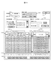
メイン画面401の例を図5に示す。501の部分で,刺激呈示の開始方法を設定する。ここでは,「MRIパルス」,「RS232C信号」,「被験者ボタン」,「単独」,の4種類から,ラジオボタンにより1つを選択する。「MRIパルス」,「RS232C」,「被験者ボタン」のいずれかを選択した場合,選択した信号の入力が右のテキストボックスの数字に達した時点で,設定した呈示パターンが開始される。「単独」を選択した場合,本刺激呈示装置のソフト単独の操作を意味し,計測者が516の開始ボタンを押下することにより,呈示パターンが開始される。502の部分では,呈示する刺激の種類を選択する。ここでは,「視覚刺激」「聴覚刺激」「視覚+聴覚刺激」の3種類を示したが,ここに「触覚刺激」や「嗅覚刺激」などを加えることも可能である。502の設定は視覚刺激単独で,主呈示を特定の感覚モダリティに決める必要はないため,主呈示のラジオボタンは設定不可となっている。 506のプルダウンメニューにより,使用する刺激呈示パターンを選択する。プルダウンメニューにより表示されるのは,502で設定した刺激種類の範疇にある既存の刺激呈示パターンである。また,呈示内容および入出力信号を記録した出力データファイルは,参照ボタン509により保存場所を選択し,ファイル名を508に記入することにより保存状況を設定する。刺激呈示パターンの選択および出力データファイルの決定後,507のチェック開始ボタンにより,設定ファイル全てにエラーがないかチェックされる。エラーがない場合,刺激呈示内容の表示部(511)に,視覚リストのファイル名(512),聴覚リストのファイル名(513),呈示テーブルのファイル名(514)および呈示テーブルの内容(518)を表示し,エラーがある場合はエラー表示を行う。刺激呈示パターンの開始と中止は,開始ボタン516と,中止ボタン517で制御されるが,図5では呈示パターンのファイルが選択されていないため,押下不可能となっている。その他,メイン画面のチェックボックス(503)では,被験者の応答の正誤判定に基づき,音声を出力するか否か決定する。チェックが入っている場合,被験者の応答に応じて,正誤を知らせる音声を出力する。また,終了ボタン(504)でメイン画面を終了する。
An example of the
刺激呈示パターンを選択し,ファイルのチェックを行った画面が図6である。刺激種類は「視覚+聴覚」を選択し,主呈示は聴覚とした(601)。呈示パターン「stroop01」(602),出力データファイル「050606ss」(603)を選択した後の画面であり,刺激の開始ボタン(608)が押下可能となっている。「視覚+聴覚刺激」のように複数の感覚刺激を与える場合,設定ファイル中どちらの感覚刺激を優先するか,「主呈示」と記した箇所のラジオボタンで設定する。これは,呈示テーブル611において,1つの刺激を呈示する時間が視覚と聴覚で異なる場合に呈示している刺激の箇所(行)がずれるため,どちらの刺激の行を優先して,共通項目(出力信号や,応答の記録)を実行するか決定する情報である。 FIG. 6 shows a screen in which the stimulus presentation pattern is selected and the file is checked. The stimulus type was “visual + auditory” and the main presentation was auditory (601). This is a screen after selecting the presentation pattern “stroop01” (602) and the output data file “050606ss” (603), and the stimulus start button (608) can be pressed. When multiple sensory stimuli such as “visual + auditory stimuli” are given, set which of the sensory stimuli has priority in the setting file with the radio button at the location marked “main presentation”. This is because, in the presentation table 611, when the time for presenting one stimulus is different between visual and auditory sense, the location (row) of the stimulus is shifted. This is information for determining whether to execute output signal or response recording.
設定した視覚リスト(604),聴覚リスト(605),呈示テーブル(606),出力ファイル(607)のファイル名と共に,呈示テーブルの詳細が下の表(611)に表示される。1列目「番号」は行番号を示し,2列目3列目の「画像番号」と「音声番号」では,それぞれ視覚リスト中の画像刺激番号と聴覚リスト中の音声刺激番号を示す。4列目「単位」は,各刺激の呈示時間を時間(ミリ秒)で設定するか,入力されたMRIパルス音の回数で設定するか,被験者からの行動反応で設定するか,あるいは脳機能信号に基づくRS232Cコマンドにより設定するか,など,刺激呈示時間を設定する単位を決める。ここでは,0を時間(ミリ秒)として設定している。MRIによる脳機能計測の場合は,MRIパルスの回数で刺激の呈示タイミングを制御することにより,目的とするタイミングの機能画像を計測することが可能となる。また,被験者の行動反応により刺激の呈示タイミングを制御すると,被験者毎に異なる行動反応時間に合わせて,適切なペースで刺激を呈示できる。更に,脳機能信号に基づくRS232Cコマンドに応じて制御すると,活動が起きた後に再び元の水準まで信号が落ち着いてから次の刺激を呈示すること等が可能となる。 Details of the presentation table are displayed in the table (611) below, along with the file names of the set visual list (604), auditory list (605), presentation table (606), and output file (607). “Number” in the first column indicates a row number, and “Image number” and “Voice number” in the second column and third column indicate an image stimulus number in the visual list and an audio stimulus number in the auditory list, respectively. In the fourth column, “Unit”, the presentation time of each stimulus is set in time (milliseconds), set by the number of input MRI pulse sounds, set by the behavioral response from the subject, or brain function Determine the unit for setting the stimulus presentation time, such as whether to set by RS232C command based on the signal. Here, 0 is set as the time (milliseconds). In the case of brain function measurement by MRI, it is possible to measure a functional image at a target timing by controlling the stimulus presentation timing by the number of MRI pulses. In addition, if the stimulus presentation timing is controlled by the subject's behavioral response, the stimulus can be presented at an appropriate pace in accordance with the behavioral response time that differs for each subject. Furthermore, if control is performed according to the RS232C command based on the brain function signal, it becomes possible to present the next stimulus after the signal has settled to the original level again after the activity has occurred.
4列目「単位」で設定した単位に応じて,画像の呈示時間(5列目)と音声の呈示時間(7列目)を設定する。この呈示時間は,被験者の行動反応の場合はボタン信号の種類,脳機能信号に基づくRS232Cコマンドの場合はコマンドの種類,を設定する場合もある。また,それらの刺激を実際に呈示した後,それぞれの実行時間を6列目,8列目に表示することによって,呈示時間の正確性を確認することが出来る。9列目では,脳機能計測装置に出力するRS232Cコマンドを設定する。例えば,呈示パターンの最初に「ST」コマンドを送り,脳機能計測装置の方で「ST」コマンドを受け取ったら計測を開始するよう設定しておけば,刺激呈示装置の操作だけで,自動的に計測を開始することが出来る。10列目には被験者からの応答として正解になる信号を設定する。実際の応答は11列目に記録され,10列目と11列目の一致を見ることにより,応答の正誤判定(12列目)が行われる。また,その行の刺激呈示後から何ミリ秒後に応答があったか計測し,応答時間(13列目)として表示される。ボタンなどの故障により正誤判定を間違わないよう,ボタン機能自体が有効だったかどうか14列目に表示する。呈示パターンの実行中は,呈示中の行を表611の選択行として示すと共に,その行番号を609(視覚刺激)と610(聴覚刺激)に表示し,計測者がリアルタイムで呈示状況を確認できるよう支援する。図6では開始ボタンの押下を待っている状況であるため,1行目が選択され,609と610にはそれぞれ「1(行目)」が表示されている。 In accordance with the unit set in the fourth column “unit”, the image presentation time (fifth column) and the voice presentation time (seventh column) are set. This presentation time may be set to the type of button signal in the case of the subject's behavior response, or to the type of command in the case of the RS232C command based on brain function signals. Moreover, after actually presenting those stimuli, the accuracy of the presentation time can be confirmed by displaying the respective execution times in the sixth and eighth columns. In the ninth column, the RS232C command to be output to the brain function measuring device is set. For example, if you send an “ST” command at the beginning of the presentation pattern and the brain function measurement device receives the “ST” command, you can set the measurement to start. Measurement can be started. In the 10th column, a signal that is correct as a response from the subject is set. The actual response is recorded in the 11th column, and the correctness / incorrectness of the response (12th column) is determined by seeing the coincidence of the 10th and 11th columns. In addition, the response time (13th column) is measured by measuring how many milliseconds after the stimulus is presented in the row. Whether or not the button function itself is effective is displayed in the 14th column so that the correctness / incorrectness determination is not mistaken due to the failure of the button or the like. During execution of the presentation pattern, the row being presented is shown as the selected row in Table 611, and the row number is displayed on 609 (visual stimulus) and 610 (auditory stimulus), allowing the measurer to check the presentation status in real time. To help. In FIG. 6, since the state is waiting for the start button to be pressed, the first line is selected, and “1 (line)” is displayed in 609 and 610, respectively.
開始前に,表611の選択行を変更することにより,開始する行を変更することも可能である。例えば,図7は,図6の設定から選択行のみを変えたものである。4行目を選択したため(703),701と702には「4(行目)」が表示され,呈示パターンの開始により4行目の刺激から呈示が始まる。呈示パターンの終了後,正誤判定から平均の正解率(519)と,平均の応答時間(521)が表示される。 It is also possible to change the starting line by changing the selected line in table 611 before starting. For example, FIG. 7 is obtained by changing only the selected row from the setting of FIG. Since the fourth row is selected (703), “4 (row)” is displayed in 701 and 702, and the presentation starts from the stimulus in the fourth row by the start of the presentation pattern. After completion of the presentation pattern, the average correct answer rate (519) and the average response time (521) are displayed from the correctness / incorrectness determination.
また、図8のようなメイン画面の構成も可能である。ここでは,呈示パターン(801)と出力データファイル(803)を設定した後,チェック開始ボタン(802)を押下した後の画面を示す。選択した呈示パターンに適した計測部位が804に図示されると共に,呈示パターンの内容として,脳機能計測装置への出力信号が806に図示される。計測部位以外にも,呈示パターンにより脳機能計測装置のパラメータを適切に設定できるよう情報を表示することが可能である。表示する情報は,適切な計測部位の場所や大きさ,計測のサンプリングピリオド,計測する光の波長などであり,画面上に表示する以外にも,直接,脳機能計測装置の該当パラメータを設定するよう構成することも可能である。これらの計測パラメータは,刺激の作成者が設定する場合と,呈示刺激から自動的に設定される場合と2通りある。後者は,例えば,呈示刺激に視覚刺激が含まれる場合,計測部位に後頭部の視覚野を含める設定を行ったり,適切な計測部位を図示し,その計測部位に適した光の波長や照射-検出間距離を脳機能計測装置に設定したり出来る。また,主な刺激の呈示時間に応じて,適切なサンプリングピリオドを設定することも出来る。この機能により,初心者の計測者でも質の高い計測データを得ることが容易になる。また,呈示パターンを図示(806)することにより,呈示パターンの全貌を把握しやすくなり,エラーの発見などが容易になる。図7の表703では4行目を選択し開始点を変更したが,図8の806では呈示パターンの進行状況を時系列として表す矢印(808)を移動することにより,開始点の変更が可能である。 A main screen configuration as shown in FIG. 8 is also possible. Here, a screen after setting the presentation pattern (801) and the output data file (803) and then pressing the check start button (802) is shown. A measurement site suitable for the selected presentation pattern is shown in 804, and an output signal to the brain function measuring device is shown in 806 as the contents of the presentation pattern. In addition to the measurement site, it is possible to display information so that the parameters of the brain function measuring device can be appropriately set according to the presentation pattern. The information to be displayed includes the location and size of the appropriate measurement site, the sampling period of measurement, the wavelength of the light to be measured, etc. In addition to displaying on the screen, the relevant parameters of the brain function measurement device are set directly It is also possible to configure as described above. These measurement parameters can be set in two ways: when set by the stimulus creator and when set automatically from the presented stimulus. In the latter case, for example, when a visual stimulus is included in the presented stimulus, the visual area of the occipital region is set to be included in the measurement site, or an appropriate measurement site is illustrated, and the light wavelength and irradiation-detection suitable for the measurement site The distance can be set in the brain function measuring device. An appropriate sampling period can also be set according to the presentation time of the main stimulus. This function makes it easy for beginners to obtain high-quality measurement data. Also, by showing (806) the presentation pattern, it becomes easier to grasp the entire picture of the presentation pattern, and it becomes easier to find errors. In Table 703 in FIG. 7, the fourth line is selected and the start point is changed, but in 806 in FIG. 8, the start point can be changed by moving the arrow (808) indicating the progress of the presentation pattern as a time series. It is.
メイン画面の外部入出力セットアップボタン(505)を押下すると,外部入出力の詳細を設定する画面図9へ遷移する。ここでは,ゲームパッドにより入力される被験者の応答,脳機能計測装置へ出力するマーカー信号(RS232C),被験者へ呈示する画面,に関するパラメーターの設定を行う。被験者の応答を4種類(応答1〜4)とし,ゲームパッドの図906により対応するボタンを設定する(905)。例えば,応答1はボタンA(901),応答2はボタンD(902),応答3はボタンE(903),応答4はボタンF(904),というようにプルダウンメニューで設定可能である。また,RS232Cの設定を912により行う。呈示パターンの開始,あるいは刺激呈示時間の指標として用いるRS232Cの入力コマンドは911で設定する。RS232Cの出力コマンドの方は,メイン画面(図6〜8)中の,表あるいは図で出力コマンドを設定する。RS232Cの入出力の詳細パラメーターに関しては,セットアップボタン(909,910)により表示される図10で設定する。詳細パラメーターは入出力共通で,例えば,転送速度(1001),データ長(1002),ストップビット(1003),パリティ(1004),ポート(1005),フロー制御(1006)等である。これらを,ラジオボタンやプルダウンメニューにより設定した後, OKボタン(1007)で保存,あるいはキャンセルボタン(1008)でキャンセルする。更に,計測者へのインターフェース画面と被験者への呈示画面を独立に使用する場合,2つの画面(マルチモニタ)の設定を915で行う。ここでは,それぞれの画面の解像度を設定するプルダウンメニュー(913,914)を示した。同様に,音声刺激や触角刺激用の設定を行うことも可能である。
When the external input / output setup button (505) on the main screen is pressed, the screen shifts to a screen shown in FIG. 9 for setting the details of the external input / output. Here, parameters related to the subject's response input by the game pad, the marker signal (RS232C) output to the brain function measuring device, and the screen presented to the subject are set. There are four types of responses of the test subjects (
再度メイン画面(図6〜8)に戻り,ファイル編集ボタン(510)の押下から始まる,呈示パターンファイルの新規作成および編集について説明する。ファイル編集ボタン(510)の押下により,はじめに図11の画面が表示され,呈示パターンのファイルを新規作成するのか,既存のファイルをベースに新規作成するのか,既にあるファイルを編集するのか,ラジオボタンで選択し,OKボタン(1101)を押下する。中止する場合は,キャンセルボタン(1102)を押下する。呈示パターンを新規作成する場合,図12のような画面が表示され,1201に呈示パターン名を入力し,OKボタン(1202)を押下する。キャンセルする場合は,キャンセルボタン(1203)の押下により戻る。既存のパターンから新規の呈示パターンを作成する場合は,図13のような画面が表示される。ベースとする既存パターンをプルダウンメニュー1301により選択し,新規に作成・保存する呈示パターン名を1302に入力する。OKボタン(1303)の押下により次に進み,キャンセルボタン(1304)の押下により戻る。既存の呈示パターンを編集する場合は,図14のような画面において,編集する既存パターンをプルダウンメニュー1401により選択する。同じく,OKボタン(1303)の押下により次に進み,キャンセルボタン(1304)の押下により戻る。
Returning to the main screen (FIGS. 6 to 8) again, new creation and editing of a presentation pattern file starting from the pressing of the file editing button (510) will be described. When the file edit button (510) is pressed, the screen shown in FIG. 11 is first displayed. Whether to create a new presentation pattern file, create a new file based on an existing file, or edit an existing file, a radio button Select with, and press the OK button (1101). To cancel, press the cancel button (1102). When a new presentation pattern is created, a screen as shown in FIG. 12 is displayed, a presentation pattern name is input in 1201, and an OK button (1202) is pressed. To cancel, return by pressing the cancel button (1203). When creating a new presentation pattern from an existing pattern, a screen as shown in FIG. 13 is displayed. An existing pattern to be used as a base is selected from the pull-
呈示パターンファイルを作成・編集する場合は,図15のような画面で設定する。メイン画面(図5〜8)で設定した刺激種類が1501に表示され,刺激種類が「視覚+聴覚」など複数の感覚刺激から成る場合は,設定した主呈示刺激も1503に表示される。作成・編集する呈示パターン名は1502に表示され,呈示テーブル名は1507,刺激リスト名は1508に表示される。それぞれ,呈示テーブルの内容は1509,刺激リストの内容は1510に表示される。呈示テーブルおよび刺激リストの内容を編集する場合,それぞれの表で編集する行を選択すると,編集部分1511にその行の内容が表示され,編集が可能となる。編集部分1511で内容を編集し,1512の更新ボタンを押すことにより内容が更新され,保存ボタンでファイルに保存される。また,新しく行を追加する場合編集部分1511に値を入力した後,登録ボタンを押下することにより行が追加される。さらに,既存の行を削除したい場合は,その行を選択し削除ボタンを押下する。また,異なる呈示テーブルファイルもしくは刺激リストファイルを使用したい場合,読込ボタンによりファイルをロードし,この呈示パターンの呈示テーブルもしくは刺激リストとして保存することが出来る。また,既にある呈示パターンを繰り返し使用し,長い呈示パターンを作成するときには,1506の「詳細パターンより作成」メニューが有効である。ここでは,参照ボタンを用いて既存の呈示テーブルファイルを読み込み,その呈示テーブルを何回繰り返すか設定した後,作成ボタンを押下する。すると,呈示テーブル1509に新しく作成された内容が表示され,1512の保存ボタン押下によりこの呈示パターンで使用される呈示テーブルとして設定される。設定後,終了ボタン1504を押下することにより,メイン画面に戻る。
When creating / editing a presentation pattern file, settings are made on a screen as shown in FIG. When the stimulus type set on the main screen (FIGS. 5 to 8) is displayed on 1501, and the stimulus type is composed of a plurality of sensory stimuli such as “visual + auditory”, the set main presentation stimulus is also displayed on 1503. The presentation pattern name to be created / edited is displayed in 1502, the presentation table name is displayed in 1507, and the stimulus list name is displayed in 1508. The contents of the presentation table are displayed at 1509 and the contents of the stimulus list are displayed at 1510, respectively. When editing the contents of the presentation table and the stimulus list, when the line to be edited is selected in each table, the contents of the line are displayed in the
上記の方法は,主に呈示テーブルの通りに指定された刺激を指定された時系列で呈示する単純な呈示パターンにおいて有効であるが,実際の計測では,刺激を無作為(ランダム)な順序で呈示したり,被験者の応答に応じて異なる刺激を呈示したりすることも必要である。呈示テーブルだけでは設定できない状況に応じて変わる刺激を「可変刺激」と定義し,1505にその情報を表示する。ここでは,3種類の可変刺激を設定し,ラジオボタンで選択した可変刺激に関して設定情報を右のテキストボックスに表示する。また,設定画面ボタンの押下により,それぞれの設定画面へ遷移する。(1)呈示する刺激やその呈示時間をランダムにするランダム刺激(図16),(2)被験者の応答(入力信号)に応じて呈示刺激および呈示時間を変化させる応答依存刺激(図17),(3)計測された被験者の脳活動に応じて呈示刺激および呈示時間を変化させる脳活動依存刺激(図18)のそれぞれの設定方法について以下に説明する。
(1) ランダム刺激の設定
ランダム刺激を用いる場合は,呈示テーブル中の刺激番号(画像番号もしくは音声番号)にR1〜R3等の記号を設定し,それぞれの記号で呈示する刺激を図16の画面で設定する。図16のランダム刺激選択メニュー1602でR1を選択した場合,1606にR1と表示され,その下のテキストボックス1608には複数の候補刺激が表示される。候補刺激は,左に表示された刺激リスト(1604)の内容(1605)から選択し,矢印ボタン(1607)の押下により追加できる。また,追加した刺激は1609の削除ボタンにより削除でき,保存ボタンにより保存できる。保存後,呈示テーブルでR1が記された行では,1608に保存した刺激からランダムに(同じ確率で)1つの刺激が選ばれ呈示される。ランダムに刺激を選択することにより,常に呈示順序が異なる呈示パターンを使用でき,繰り返し計測に参加する被験者の馴れを防ぐ効果が期待できる。また,計測者が複数の刺激呈示パターンを作成する場合,刺激パターンの数に応じた労力が必要であるため,計測者の作業低減という点においても有効である。
The above method is effective for simple presentation patterns that present stimuli specified according to the presentation table in the specified time series, but in actual measurement, the stimuli are in random (random) order. It is also necessary to present different stimuli depending on the subject's response. A stimulus that changes depending on the situation that cannot be set only by the presentation table is defined as “variable stimulus”, and the information is displayed in 1505. Here, three types of variable stimulus are set, and setting information regarding the variable stimulus selected with the radio button is displayed in the right text box. In addition, each setting screen is transitioned to by pressing a setting screen button. (1) Stimulus to present and random stimulus to randomize the presentation time (FIG. 16), (2) Response dependent stimulus to change the presentation stimulus and the presentation time according to the response (input signal) of the subject (FIG. 17), (3) Each setting method of the brain activity-dependent stimulus (FIG. 18) for changing the presentation stimulus and the presentation time according to the measured brain activity of the subject will be described below.
(1) Random stimulus setting When using random stimuli, symbols such as R1 to R3 are set in the stimulus number (image number or voice number) in the presentation table, and the stimulus presented by each symbol is displayed on the screen of FIG. Set with. When R1 is selected in the random
続けて同じ刺激を呈示しない,もしくはある刺激の後は常にこの刺激を呈示する,など,R1で呈示された刺激に応じて,次に呈示される刺激(ポストランダム刺激)を変化させなければならない計測パラダイムも存在する。その場合,呈示テーブル中の刺激番号にR等の記号を設定し,R1Rとして(1602〜1604)で設定する。1608で表示したR1の候補刺激の1つ目を選択すると,その刺激の呈示後に呈示する刺激R1R(1611)をテキストボックス(1612)に設定できる。左のリスト内容1605から呈示する刺激を選択し,R1と同様に矢印ボタン1610を押下すると,テキストボックス1612に追加される。また,1613の削除ボタンで刺激を削除,保存ボタンでリスト1612を保存できる。その他のR1の候補刺激も同様に,次に呈示するポストランダム刺激を設定できる。R1同様,複数の刺激を選択することにより,ランダムに1つの刺激が呈示される。刺激に応じて選択確率を変えたい場合,テキストボックス1608や1612中に同一の刺激を数個入れることにより確率を変えることが出来る。
The next presented stimulus (post-random stimulus) must be changed according to the stimulus presented in R1, such as not presenting the same stimulus continuously or always presenting this stimulus after a certain stimulus. There is also a measurement paradigm. In that case, a symbol such as R is set for the stimulus number in the presentation table, and R1R is set as (1602 to 1604). When the first candidate stimulus of R1 displayed in 1608 is selected, the stimulus R1R (1611) to be presented after the presentation of the stimulus can be set in the text box (1612). When a stimulus to be presented is selected from the
呈示時間をランダムに設定したい場合,呈示テーブル中の画像呈示時間もしくは音声呈示時間にR1T〜R3T等の記号を設定し,それぞれの記号での呈示時間を図16の画面で設定する。例えば,図16のランダム呈示時間設定メニュー1603でR1Tを選択し,右のテキストボックスに呈示時間の下限と上限を設定することにより(例. 10〜20秒),R1Tと設定した刺激の呈示時間は,10秒間〜20秒間の間でランダムに決定される。R2TとR3Tも同様に設定できる。設定後,終了ボタン1601の押下により,ファイル編集画面に戻る。呈示時間をランダム化することにより,被験者は次の刺激(課題)が呈示されるタイミングを予測することが困難になり,予測的な行動反応を回避することが出来る。また,自発的に生じる信号のゆらぎ周期はほぼ一定であるため,刺激呈示タイミングをランダム化されることにより,自発的な揺らぎが偶然に同じタイミングで加算平均され,刺激呈示に伴う脳活動信号と重なることを防ぐ効果もある。
(2) 応答依存刺激の設定
被験者の応答(入力信号)に応じて呈示刺激および呈示時間を変化させる場合,応答依存刺激として図17で設定する。被験者の応答を3種類(S1〜S3)の参照刺激2(図1〜3)とした場合,被験者応答をラジオボタン1701で選択し,該当する被験者応答を得た次の刺激呈示時間を呈示時間設定メニュー1705で,次に呈示する刺激を呈示刺激設定メニュー1707で,それぞれ設定する。呈示刺激は,左に表示された刺激リスト1703の内容1704から選択し,矢印ボタン1706の押下により選択,保存できる。複数の刺激を選択することにより,図16で説明した方法でランダム刺激として用いることも可能である。この機能により,被験者の反応に応じて次の刺激を変化させられるため,フレキシブルな呈示パターンが可能となる。例えば,画面に呈示される視覚刺激の快・不快を評価させ情動に伴う脳活動を計測する場合,快と評価した後の次の刺激は,必ず不快群からランダムに選択する,という呈示方法が可能である。このような課題の正誤を一律に決められないような刺激パラダイムの場合に,刺激間のカウンターバランスを取る上で有用である。
When it is desired to set the presentation time at random, symbols such as R1T to R3T are set for the image presentation time or the voice presentation time in the presentation table, and the presentation time for each symbol is set on the screen of FIG. For example, by selecting R1T in the random presentation
(2) Setting of response-dependent stimulus When changing the presentation stimulus and the presentation time according to the response (input signal) of the subject, it is set as a response-dependent stimulus in FIG. When the response of the subject is 3 types (S1 to S3) of the reference stimulus 2 (FIGS. 1 to 3), the subject response is selected with the
また,S1〜3を参照刺激の分類として割り当てずに,参照刺激から判定した行動反応の正誤として使用することも可能である。その場合,正解の時には,より難易度の高い問題へ,不正解の場合は,同じレベルの問題へ進む,というように,被験者の状態に応じた刺激を呈示することが出来る。また,1702のフィードバックコントロール設定画面では,フィードバックコントロール機能の有無を選択できる。フィードバックコントロール機能とは,被験者の正答率と反応時間によるフィードバックコントロールを「有」とした場合に,設定した正答率(%)と反応時間(ms)に近づくように,次の刺激を選択する機能である。つまり,正答率が設定した割合より低い場合,出来るだけ簡単な課題から選択し,逆に設定した割合より高い場合は,難しい課題から選択する。同様に,平均の反応時間が設定した反応時間に近づくように,次に呈示する課題を適切なレベルの課題群から選択する機能である。この機能により,課題に対する能力が異なる被験者においても,呈示刺激(課題)を統制することにより,近似した値の負荷を与えることが可能となる。つまり,脳機能計測において常に問題となる個人差について,刺激(課題)の負荷という観点からは,個人毎に従来より最適化することが出来るため,被験者間の脳活動を精度よく比較する上で有効な機能である。
(3) 脳活動依存刺激の設定
被験者の脳活動に応じて呈示刺激および呈示時間を変化させる場合,脳活動依存刺激として図18で設定する。脳機能計測装置106(図1〜3)で計測した脳活動信号は信号処理装置107(図1〜2)で解析され,例えば,「無刺激時の標準偏差(SD)の2倍を超える振幅の正の脳活動信号が生じて,その後,刺激前の安静状態における信号強度(ベースライン)まで戻った場合(増加(+2SD⇒ベースライン))」や,「無刺激時のSDの2倍を超える振幅の負の脳活動信号が生じて,その後,ベースラインまで戻った場合(減少(+2SD⇒ベースライン))」等に分類し,参照信号1(図1,2)として刺激呈示装置へ送る。1801の脳活動信号の選択メニューでは,脳活動依存刺激の選択に用いる脳活動信号を選択した後(本実施例では,oxy-Hb,deoxy-Hb,total-Hbから選択),更に参照信号1が表す分類した脳活動信号のパターンを選択する(本実施例では,「A:増加(+2SD)⇒ベースライン」と「B:減少(―2SD)⇒ベースライン」から選択)。該当する脳活動信号を示す参照信号を得た次の刺激呈示時間を呈示時間設定メニュー1804で,次に呈示する刺激を呈示刺激設定メニュー1806で,それぞれ設定する。呈示刺激は,左に表示された刺激リスト1802の内容1803から選択し,矢印ボタン1805の押下により選択,保存できる。複数の刺激を選択することにより,図16で説明した方法でランダム刺激として用いることも可能である。この機能により,刺激呈示に伴い生じた脳活動信号が,再び刺激呈示前の水準に戻った時点を基準に次の刺激を呈示することが可能となるため,出来るだけ短い刺激―刺激間隔が実現できる。つまり,被験者によって異なるリラクゼーション時間を考慮して,刺激と刺激の間隔を調整できるため,常に従来より短い刺激―刺激間隔を設定することにより計測時間を短縮して,被験者の負担を軽減することができる。
Moreover, it is also possible to use S1-3 as correct / incorrect behavioral responses determined from the reference stimulus without assigning S1 to 3 as the reference stimulus classification. In this case, it is possible to present a stimulus according to the condition of the subject, such that when the answer is correct, the problem is more difficult, and when the answer is incorrect, the problem is the same level. On the 1702 feedback control setting screen, the presence or absence of the feedback control function can be selected. The feedback control function is a function that selects the next stimulus so that the correct answer rate (%) and reaction time (ms) are close to each other when the feedback control based on the correct answer rate and the reaction time of the subject is “Yes”. It is. In other words, when the correct answer rate is lower than the set rate, the task is selected as simple as possible, and when it is higher than the set rate, the difficult task is selected. Similarly, it is a function that selects a task to be presented next from a task group at an appropriate level so that the average reaction time approaches the set reaction time. With this function, subjects with different abilities to tasks can be given a load with an approximate value by controlling the presentation stimulus (task). In other words, individual differences that are always a problem in brain function measurement can be optimized from the viewpoint of stimulation (task) for each individual, so that the brain activity between subjects can be compared accurately. This is an effective function.
(3) Setting of brain activity dependent stimulus When changing the presentation stimulus and the presentation time according to the brain activity of the subject, it is set as the brain activity dependent stimulus in FIG. Brain activity signals measured by the brain function measuring device 106 (Figs. 1 to 3) are analyzed by the signal processing device 107 (Figs. 1 and 2). When a positive brain activity signal is generated and then it returns to the signal strength (baseline) in the resting state before stimulation (increased (+ 2SD⇒baseline)) "or" double SD of unstimulated SD If a negative brain activity signal with an amplitude greater than that occurs and then returns to the baseline (decrease (+ 2SD⇒baseline)), etc., and sends it to the stimulus presentation device as reference signal 1 (Figs. 1 and 2) . In the brain activity signal selection menu of 1801, after selecting a brain activity signal to be used for selecting a brain activity dependent stimulus (in this embodiment, selected from oxy-Hb, deoxy-Hb, and total-Hb), the reference signal 1 (In this example, select from “A: increase (+ 2SD) → baseline” and “B: decrease (−2SD) → baseline”). The next stimulus presentation time when the reference signal indicating the corresponding brain activity signal is obtained is set by the presentation
また,応答(2)や脳活動(3)の代わりに,実際の被験者の様子を計測者が観察して,刺激呈示を決定することもあり得る。その場合,例えば,計測者は図20のようなインターフェースにより表示される計測風景2001を見ながら刺激呈示ボタン2002〜2005を押下することにより刺激1〜4を呈示することが出来る。終了ボタン2006により元の画面に戻る。
In addition, instead of the response (2) and the brain activity (3), the measurer may observe the actual state of the subject and determine the stimulus presentation. In this case, for example, the measurer can present the
以上のように,本発明の脳機能計測用刺激呈示装置を用いることにより,被験者毎に従来より最適化された刺激呈示を実行でき,より高精度で、また効率のよい脳機能計測が可能となる。また,脳機能計測装置に対して適切な計測パラメータ設定を支援する機能も有し,初心者の計測者でも質の高い計測データを得ることができる。また,被験者によって異なるリラクゼーション時間を考慮して,刺激と刺激の間隔を調整できるため,従来より短い刺激―刺激間隔を設定することが可能となり,計測時間を短縮して被験者の負担を軽減することができる。更に,特別なプログラミング能力を必要とせずに刺激呈示パターンを作成・編集することが可能となり,幅広い脳機能計測の応用へ役立つ支援ツールとなる。作成した刺激呈示パターンは,刺激ファイル(画像ファイルや音声ファイル)と表ファイルで管理できるため,容易に配布,編集,使用することが出来る。 As described above, by using the stimulus presentation device for brain function measurement according to the present invention, it is possible to execute stimulus presentation optimized for each subject, and to perform brain function measurement with higher accuracy and efficiency. Become. It also has a function to support appropriate measurement parameter setting for the brain function measuring device, and even a beginner measurer can obtain high-quality measurement data. In addition, since the interval between stimuli can be adjusted in consideration of the relaxation time that varies depending on the subject, it is possible to set a shorter stimulus-stimulus interval than before, reducing the measurement time and reducing the burden on the subject. Can do. Furthermore, it is possible to create and edit stimulus presentation patterns without requiring special programming skills, and it will be a useful support tool for a wide range of brain function measurement applications. The created stimulus presentation patterns can be managed by stimulus files (image files and audio files) and table files, so they can be easily distributed, edited, and used.
101…計測者のユーザーインターフェース,102…刺激呈示装置,103…画像呈示用ディスプレイ,104…音声呈示用スピーカー,105…触覚刺激呈示用振動ボックス,106…脳機能計測装置,107…脳機能信号の処理装置,108…被験者応答の処理装置,
401…メイン画面,402…ファイル編集画面,403…入出力設定画面,404…ランダム刺激設定画面,405…応答依存刺激設定画面,406…脳活動信号依存刺激設定画面,
501…開始信号の設定メニュー,502…刺激種類の設定メニュー,503…正誤判定の音声出力設定メニュー,504…終了ボタン,505…外部入出力セットアップボタン,506…呈示パターン選択のプルダウンメニュー,507…チェック開始ボタン,508…出力データファイル名の入力ボックス,509…出力データファイルの参照ボタン,510…ファイル編集ボタン,511…呈示する刺激内容の表示部,512…視覚リスト名表示部,513…聴覚リスト名表示部,514…呈示テーブル名表示部,515…出力ファイル名表示部,516…呈示パターンの開始ボタン,517…呈示パターンの中止ボタン,518…呈示中の視覚刺激番号の表示部,519…応答正解率の表示部,520…呈示中の聴覚刺激番号の表示部,521…平均応答時間の表示部,522…呈示テーブルの内容表示部,
601…刺激種類の設定メニュー,602…呈示パターン選択のプルダウンメニュー,603…出力データファイル名の入力ボックス,604…視覚リスト名表示部,605…聴覚リスト名表示部,606…呈示テーブル名表示部,607…出力ファイル名表示部,608…呈示パターンの開始ボタン,609…呈示中の視覚刺激番号の表示部,610…呈示中の聴覚刺激番号の表示部,611…呈示テーブルの内容表示部,
701…呈示中の視覚刺激番号の表示部,702…呈示中の聴覚刺激番号の表示部,703…呈示テーブルの内容表示部,
801…呈示パターン選択のプルダウンメニュー,802…チェック開始ボタン,803…出力データファイル名の入力ボックス,804…選択した呈示パターンに適した計測部位の表示部,805…呈示パターンの開始ボタン, 806…呈示テーブルの内容表示部(図示),807…呈示パターンの中止ボタン,
901…応答1のボタン設定部,902…応答2のボタン設定部,903…応答3のボタン設定部,904…応答4のボタン設定部,905…被験者応答の入力装置となるゲームパッドの図,906…被験者応答の入力装置となるゲームパッドの設定メニュー,907…OKボタン,908…キャンセルボタン,909…RS232C入力のセットアップボタン,910…RS232C出力のセットアップボタン,911…RS232Cの入力コマンド設定メニュー,912…RS232C入出力の設定メニュー,913…メイン(計測者インターフェース)画面の解像度設定プルダウンメニュー,914…刺激呈示画面の解像度設定プルダウンメニュー,915…画面(マルチモニタ)設定メニュー,
1001…転送速度の設定部,1002…データ長の設定部,1003…ストップビットの設定部,1004…パリティの設定部,1005…ポートの設定部,1006…フロー制御の設定部,1007…OKボタン,1008…キャンセルボタン,
1101…OKボタン,1102…キャンセルボタン,
1201…新規に作成する呈示パターン名の入力部,1202…OKボタン,1203…キャンセルボタン,
1301…ベースとなる呈示パターンの選択部,1302…新規に作成する呈示パターン名の入力部,1303…OKボタン,1304…キャンセルボタン,
1401…編集する呈示パターンの選択部,1402…OKボタン,1403…キャンセルボタン,
1501…選択した刺激種類の表示部,1502…選択した呈示パターンの表示部,1503…主呈示となる刺激種類の表示部と表示の設定部,1504…終了ボタン,1505…可変刺激情報の表示および選択部,1506…詳細パターンより新規の呈示テーブルを作成するメニュー,1507…呈示テーブル名の表示部,1508…刺激リスト名の表示部,1509…呈示テーブルの内容表示部,1510…刺激リストの内容表示部,1511…呈示テーブルおよび刺激リストの編集部分,1512…呈示テーブルおよび刺激リストの編集結果を更新,登録,削除,読込,保存するメニュー,
1601…終了ボタン,1602…ランダム刺激の選択部,1603…ランダム呈示時間の設定メニュー,1604…刺激リスト名の表示部,1605…刺激リストの内容表示部,1606…ランダム刺激表示部,1607…ランダム刺激として選択される候補刺激の表示部,1608…ランダム刺激の候補刺激を選択する矢印ボタン,1609…ランダム刺激の保存,削除メニュー,1610…ポストランダム刺激の候補刺激を選択する矢印ボタン,1611…ポストランダム刺激表示部,1612…ポストランダム刺激として選択される候補刺激の表示部,1613…ポストランダム刺激の保存,削除メニュー,
1701…被験者応答の選択部,1702…フィードバックコントロールの設定部,1703…刺激リスト名の表示部,1704…刺激リストの内容表示部,1705…被験者応答依存刺激の呈示時間設定メニュー,1706…被験者応答刺激を選択する矢印ボタン,1707…被験者応答刺激の表示部,
1801…脳活動信号の選択部,1802…刺激リスト名の表示部,1803…刺激リストの内容表示部,1804…脳活動信号依存刺激の呈示時間設定メニュー,1805…脳活動信号依存刺激を選択する矢印ボタン,1806…脳活動信号依存刺激の表示部,1901…制御装置,1902…アナログデジタル変換機,1903…ロックインアンプ,1904…ロックインアンプ,1905…発振器,1906…発振器,1907…光源,1908…光源,1909…光混合器,1910…光検出器,1911…ディスプレイ,2001…計測風景表示画面,2002…刺激1呈示ボタン,2003…刺激2呈示ボタン,2004…刺激3呈示ボタン,2005…刺激1呈示ボタン,2006…終了ボタン。
101 ... Measurer's user interface, 102 ... Stimulus presentation device, 103 ... Display for image presentation, 104 ... Speaker for voice presentation, 105 ... Vibration box for tactile stimulus presentation, 106 ... Brain function measurement device, 107 ... Brain function signal Processing device, 108 ... Subject response processing device,
401 ... main screen, 402 ... file editing screen, 403 ... input / output setting screen, 404 ... random stimulus setting screen, 405 ... response-dependent stimulus setting screen, 406 ... brain activity signal-dependent stimulus setting screen,
501 ... Start signal setting menu, 502 ... Stimulus type setting menu, 503 ... Sound output setting menu for correct / incorrect judgment, 504 ... Exit button, 505 ... External input / output setup button, 506 ... Pull-down menu for presentation pattern selection, 507 ... Check start button, 508 ... Output data file name input box, 509 ... Output data file reference button, 510 ... File edit button, 511 ... Stimulus content display section, 512 ... Visual list name display section, 513 ... Hearing List name display section, 514 ... presentation table name display section, 515 ... output file name display section, 516 ... present pattern start button, 517 ... present pattern stop button, 518 ... visual stimulus number display section during presentation, 519 ... response correct answer display unit, 520 ... display unit of auditory stimulus number being presented, 521 ... display unit of average response time, 522 ... content display unit of presentation table,
601 ... Stimulus type setting menu, 602 ... Presentation pattern selection pull-down menu, 603 ... Output data file name input box, 604 ... Visual list name display section, 605 ... Auditory list name display section, 606 ... Presentation table name display section , 607 ... Output file name display section, 608 ... Presentation pattern start button, 609 ... Display section of visual stimulus number being presented, 610 ... Display section of auditory stimulus number being presented, 611 ... Contents display section of presentation table,
701 ... Display unit of visual stimulus number being presented, 702 ... Display unit of auditory stimulus number being presented, 703 ... Content display part of presentation table,
801 ... Pull-down menu for selection of presentation pattern, 802 ... Check start button, 803 ... Input box for output data file name, 804 ... Display part of measurement part suitable for the selected presentation pattern, 805 ... Start button for presentation pattern, 806 ... Presentation table content display section (illustrated), 807...
901 ... button setting unit for
1001 ... Transfer rate setting section, 1002 ... Data length setting section, 1003 ... Stop bit setting section, 1004 ... Parity setting section, 1005 ... Port setting section, 1006 ... Flow control setting section, 1007 ... OK button , 1008 ... Cancel button,
1101 ... OK button, 1102 ... Cancel button,
1201 ... Input section for newly created presentation pattern name, 1202 ... OK button, 1203 ... Cancel button,
1301 ... Selection section for a presentation pattern as a base, 1302 ... Input section for a newly created presentation pattern name, 1303 ... OK button, 1304 ... Cancel button,
1401 ... selection part of the presentation pattern to be edited, 1402 ... OK button, 1403 ... cancel button,
1501 ... Display unit of selected stimulus type, 1502 ... Display unit of selected presentation pattern, 1503 ... Display unit and display setting unit of stimulus type to be main presentation, 1504 ... End button, 1505 ... Display of variable stimulus information and Selection part, 1506 ... Menu for creating a new presentation table from detailed patterns, 1507 ... Display part of presentation table name, 1508 ... Display part of stimulus list, 1509 ... Display part of presentation table, 1510 ... Contents of stimulus list Display unit, 1511 ... Editing part of the presentation table and stimulus list, 1512 ... Menu for updating, registering, deleting, reading and saving the edit result of the presentation table and stimulus list,
1601 ... End button, 1602 ... Random stimulus selection unit, 1603 ... Random presentation time setting menu, 1604 ... Stimulus list name display unit, 1605 ... Stimulus list content display unit, 1606 ... Random stimulus display unit, 1607 ... Random Candidate stimulus display section selected as a stimulus, 1608 ... Arrow button for selecting a random stimulus candidate stimulus, 1609 ... Random stimulus save / delete menu, 1610 ... Arrow button for selecting a post-random stimulus candidate stimulus, 1611 ... Post-random stimulus display section, 1612 ... Display section of candidate stimulus selected as post-random stimulus, 1613 ... Save post-random stimulus, delete menu,
1701 ... Subject response selection unit, 1702 ... Feedback control setting unit, 1703 ... Stimulus list name display unit, 1704 ... Stimulus list content display unit, 1705 ... Subject response dependent stimulus presentation time setting menu, 1706 ... Subject response Arrow buttons to select stimuli, 1707 ... Subject response stimulus display,
1801 ... Brain activity signal selection unit, 1802 ... Stimulus list name display unit, 1803 ... Stimulus list content display unit, 1804 ... Brain activity signal dependent stimulus presentation time setting menu, 1805 ... Brain activity signal dependent stimulus selection Arrow button, 1806 ... Display unit of brain activity signal dependent stimulus, 1901 ... Control device, 1902 ... Analog to digital converter, 1903 ... Lock-in amplifier, 1904 ... Lock-in amplifier, 1905 ... Oscillator, 1906 ... Oscillator, 1907 ... Light source, 1908 ... light source, 1909 ... light mixer, 1910 ... light detector, 1911 ... display, 2001 ... measurement scenery display screen, 2002 ...
Claims (8)
前記被検体の脳機能を計測する脳機能計測装置と、
前記刺激呈示手段が呈示する刺激の種類またはタイミングを表またはテーブルまたはグラフで編集する設定部と、
前記被検体の前記刺激に対する応答を認識する応答処理装置を有し、
前記設定部は、前記応答処理装置で認識された前記被検体の応答結果に応じて自動的に選択される刺激の種類を設定できることを特徴とする脳機能計測用刺激呈示装置。 A stimulus presentation means for presenting a sensory stimulus to the subject;
A brain function measuring device for measuring the brain function of the subject;
A setting unit for editing the type or timing of the stimulus presented by the stimulus presenting means in a table or a table or a graph ;
A response processing device for recognizing a response of the subject to the stimulus;
The stimulation display device for brain function measurement , wherein the setting unit can set a type of stimulation that is automatically selected according to a response result of the subject recognized by the response processing device.
3)前記脳機能計測装置による前記被検体の脳機能計測結果に応じて与えるか、を選択する選択部を有することを特徴とする請求項1記載の脳機能計測用刺激呈示装置。3. The stimulation presentation device for brain function measurement according to claim 1, further comprising a selection unit that selects whether to give the brain function measurement result of the subject by the brain function measurement device.
Priority Applications (1)
| Application Number | Priority Date | Filing Date | Title |
|---|---|---|---|
| JP2005240551A JP4655821B2 (en) | 2005-08-23 | 2005-08-23 | Stimulus display device for brain function measurement |
Applications Claiming Priority (1)
| Application Number | Priority Date | Filing Date | Title |
|---|---|---|---|
| JP2005240551A JP4655821B2 (en) | 2005-08-23 | 2005-08-23 | Stimulus display device for brain function measurement |
Publications (3)
| Publication Number | Publication Date |
|---|---|
| JP2007054138A JP2007054138A (en) | 2007-03-08 |
| JP2007054138A5 JP2007054138A5 (en) | 2008-05-08 |
| JP4655821B2 true JP4655821B2 (en) | 2011-03-23 |
Family
ID=37918155
Family Applications (1)
| Application Number | Title | Priority Date | Filing Date |
|---|---|---|---|
| JP2005240551A Active JP4655821B2 (en) | 2005-08-23 | 2005-08-23 | Stimulus display device for brain function measurement |
Country Status (1)
| Country | Link |
|---|---|
| JP (1) | JP4655821B2 (en) |
Families Citing this family (15)
| Publication number | Priority date | Publication date | Assignee | Title |
|---|---|---|---|---|
| DE102007013855A1 (en) * | 2007-03-20 | 2008-09-25 | Merck Patent Gmbh | Substituted tetrahydroquinolines |
| JP5347312B2 (en) * | 2008-04-16 | 2013-11-20 | 株式会社島津製作所 | Light measuring device |
| JP5319960B2 (en) * | 2008-05-28 | 2013-10-16 | 株式会社日立製作所 | Biological light measurement device |
| CN102056549B (en) | 2008-06-04 | 2013-05-15 | 株式会社日立医疗器械 | Stimulation subject presentation device for living body optical measurement apparatus and method for presenting stimulation subject |
| JP5210733B2 (en) * | 2008-07-07 | 2013-06-12 | 株式会社日立メディコ | Biological light measuring device having stimulation presentation function and stimulation task presentation method |
| JP5330016B2 (en) * | 2009-02-16 | 2013-10-30 | 株式会社東芝 | Magnetic resonance imaging system |
| JP5402252B2 (en) * | 2009-05-28 | 2014-01-29 | ヤマハ株式会社 | Operation evaluation apparatus and program |
| JP5402253B2 (en) * | 2009-05-28 | 2014-01-29 | ヤマハ株式会社 | Operation evaluation apparatus and program |
| US20160005058A1 (en) * | 2012-11-26 | 2016-01-07 | Hitachi, Ltd. | Sensitivity evaluation system |
| JP6477280B2 (en) * | 2015-06-16 | 2019-03-06 | 株式会社島津製作所 | Cognitive brain activity measurement system and cognitive brain activity measurement method |
| JP6382789B2 (en) * | 2015-12-14 | 2018-08-29 | 日本電信電話株式会社 | Perceptual sensitivity evaluation apparatus, method and program |
| JP2017118912A (en) * | 2015-12-28 | 2017-07-06 | 学校法人自治医科大学 | Method for determining optimum way of giving attention for promoting effect of exercise learning |
| JP6885568B2 (en) | 2016-09-28 | 2021-06-16 | 株式会社NeU | Selection system, selection method, and selection program |
| JP7069716B2 (en) * | 2017-12-28 | 2022-05-18 | 株式会社リコー | Biological function measurement and analysis system, biological function measurement and analysis program, and biological function measurement and analysis method |
| JP7176445B2 (en) * | 2019-03-13 | 2022-11-22 | 株式会社リコー | Brain reaction measurement system, brain reaction measurement method, and brain reaction measurement program |
Citations (4)
| Publication number | Priority date | Publication date | Assignee | Title |
|---|---|---|---|---|
| JPH053920A (en) * | 1991-06-25 | 1993-01-14 | Matsushita Electric Works Ltd | Biorhythm adjusting device |
| JP2002541891A (en) * | 1999-04-20 | 2002-12-10 | ニコレット バイオメディカル インコーポレイテッド | Monitoring and display of medical signals |
| JP2003210429A (en) * | 2002-01-21 | 2003-07-29 | Nippon Koden Corp | Bio-stimulating device and heart stimulating examination device |
| JP2004041456A (en) * | 2002-07-12 | 2004-02-12 | Ge Medical Systems Global Technology Co Llc | Apparatus for injecting chemical substsance and method threfor |
-
2005
- 2005-08-23 JP JP2005240551A patent/JP4655821B2/en active Active
Patent Citations (4)
| Publication number | Priority date | Publication date | Assignee | Title |
|---|---|---|---|---|
| JPH053920A (en) * | 1991-06-25 | 1993-01-14 | Matsushita Electric Works Ltd | Biorhythm adjusting device |
| JP2002541891A (en) * | 1999-04-20 | 2002-12-10 | ニコレット バイオメディカル インコーポレイテッド | Monitoring and display of medical signals |
| JP2003210429A (en) * | 2002-01-21 | 2003-07-29 | Nippon Koden Corp | Bio-stimulating device and heart stimulating examination device |
| JP2004041456A (en) * | 2002-07-12 | 2004-02-12 | Ge Medical Systems Global Technology Co Llc | Apparatus for injecting chemical substsance and method threfor |
Also Published As
| Publication number | Publication date |
|---|---|
| JP2007054138A (en) | 2007-03-08 |
Similar Documents
| Publication | Publication Date | Title |
|---|---|---|
| JP4655821B2 (en) | Stimulus display device for brain function measurement | |
| EP3052174B1 (en) | System for determining timing of sensory stimulation during sleep | |
| JP4241913B2 (en) | Training support device | |
| JP5399251B2 (en) | Method and system for acquiring data for inspecting an infant who exhibits impaired hearing processing or for improving the auditory or visual information processing of a normally growing infant | |
| Myrden et al. | A brain-computer interface based on bilateral transcranial Doppler ultrasound | |
| US10307100B2 (en) | Methods and systems of controlling a subject's body feature having a periodic wave function | |
| JP4378957B2 (en) | Physiological state induction device | |
| EP3381353A1 (en) | Method for planning an imaging scan protocol | |
| JP5462941B2 (en) | Fatigue evaluation system | |
| US20220338785A1 (en) | Information processing apparatus, information processing system, and non-transitory computer readable medium | |
| JP2008516701A (en) | Physiological monitoring method and apparatus | |
| JP5484324B2 (en) | Stimulation task presentation device in biological light measurement device | |
| US10987014B2 (en) | Information processing apparatus, information processing system, and non-transitory computer readable medium | |
| US8624741B2 (en) | Pulse oximeter alarm simulator and training tool | |
| JP6475132B2 (en) | Diagnostic assistance system and diagnostic assistance information display method | |
| WO2020260060A1 (en) | Apparatus for patient sedation monitoring | |
| JP2003159253A (en) | Stimulus providing device to subject for measuring brain function | |
| US20050261557A1 (en) | Computer-based method and apparatus for evaluation of sensory and physiological parameters | |
| JP5210733B2 (en) | Biological light measuring device having stimulation presentation function and stimulation task presentation method | |
| US20230255491A1 (en) | Emdr thrapy analysis | |
| CN114470475A (en) | Scene type cognitive guide sound wave treatment system | |
| Blanco et al. | gVARVI: A graphical software tool for the acquisition of the heart rate in response to external stimuli | |
| CA2466410A1 (en) | Method and apparatus for evaluation of sensory and physiological parameters | |
| US20230168738A1 (en) | Methods and systems for controlling a haptic display | |
| JP6093142B2 (en) | Brain activity training support device using biological light measurement device, signal processing program, and signal processing method |
Legal Events
| Date | Code | Title | Description |
|---|---|---|---|
| A521 | Request for written amendment filed |
Free format text: JAPANESE INTERMEDIATE CODE: A523 Effective date: 20080324 |
|
| A621 | Written request for application examination |
Free format text: JAPANESE INTERMEDIATE CODE: A621 Effective date: 20080324 |
|
| A977 | Report on retrieval |
Free format text: JAPANESE INTERMEDIATE CODE: A971007 Effective date: 20100916 |
|
| TRDD | Decision of grant or rejection written | ||
| A01 | Written decision to grant a patent or to grant a registration (utility model) |
Free format text: JAPANESE INTERMEDIATE CODE: A01 Effective date: 20101130 |
|
| A01 | Written decision to grant a patent or to grant a registration (utility model) |
Free format text: JAPANESE INTERMEDIATE CODE: A01 |
|
| A61 | First payment of annual fees (during grant procedure) |
Free format text: JAPANESE INTERMEDIATE CODE: A61 Effective date: 20101213 |
|
| FPAY | Renewal fee payment (event date is renewal date of database) |
Free format text: PAYMENT UNTIL: 20140107 Year of fee payment: 3 |
|
| R151 | Written notification of patent or utility model registration |
Ref document number: 4655821 Country of ref document: JP Free format text: JAPANESE INTERMEDIATE CODE: R151 |
|
| FPAY | Renewal fee payment (event date is renewal date of database) |
Free format text: PAYMENT UNTIL: 20140107 Year of fee payment: 3 |