JP4654004B2 - Image forming apparatus - Google Patents
Image forming apparatus Download PDFInfo
- Publication number
- JP4654004B2 JP4654004B2 JP2004329854A JP2004329854A JP4654004B2 JP 4654004 B2 JP4654004 B2 JP 4654004B2 JP 2004329854 A JP2004329854 A JP 2004329854A JP 2004329854 A JP2004329854 A JP 2004329854A JP 4654004 B2 JP4654004 B2 JP 4654004B2
- Authority
- JP
- Japan
- Prior art keywords
- laser beam
- mirror
- image
- polygon mirror
- image carrier
- Prior art date
- Legal status (The legal status is an assumption and is not a legal conclusion. Google has not performed a legal analysis and makes no representation as to the accuracy of the status listed.)
- Expired - Fee Related
Links
Images


Classifications
-
- H—ELECTRICITY
- H04—ELECTRIC COMMUNICATION TECHNIQUE
- H04N—PICTORIAL COMMUNICATION, e.g. TELEVISION
- H04N1/00—Scanning, transmission or reproduction of documents or the like, e.g. facsimile transmission; Details thereof
- H04N1/46—Colour picture communication systems
- H04N1/50—Picture reproducers
- H04N1/506—Reproducing the colour component signals picture-sequentially, e.g. with reproducing heads spaced apart from one another in the subscanning direction
Landscapes
- Engineering & Computer Science (AREA)
- Multimedia (AREA)
- Signal Processing (AREA)
- Exposure Or Original Feeding In Electrophotography (AREA)
- Electrophotography Configuration And Component (AREA)
- Color Electrophotography (AREA)
- Mechanical Optical Scanning Systems (AREA)
- Laser Beam Printer (AREA)
Description
本発明は、シート等の転写材(記録媒体)上に画像を形成する機能を備えた、例えば、複写機、プリンタ、あるいは、ファクシミリ装置などの画像形成装置に関するものである。 The present invention relates to an image forming apparatus having a function of forming an image on a transfer material (recording medium) such as a sheet, such as a copying machine, a printer, or a facsimile machine.
従来、カラー画像形成装置においては、イエロー、マゼンタ、シアン、ブラックの各色に対して独立した像担持体としての感光体を有し、各感光体にレーザ光を露光して静電潜像を形成し、この静電潜像を各色のトナーで現像し、得られる各トナー画像を中間転写ベルトに順次転写して重ね合わせた後、シート状の記録媒体上に一括転写してカラー画像を得るタンデム型のカラー画像形成装置が知られている。 Conventionally, a color image forming apparatus has a photoreceptor as an independent image carrier for each color of yellow, magenta, cyan, and black, and forms an electrostatic latent image by exposing each photoreceptor to laser light. Then, the electrostatic latent image is developed with toner of each color, and each obtained toner image is sequentially transferred onto the intermediate transfer belt and superimposed, and then transferred onto a sheet-like recording medium to obtain a color image. A type of color image forming apparatus is known.
このようなタンデム型のカラー画像形成装置において、感光体にレーザ光を露光する走査式光学装置は、画像情報に基づいてレーザ光を発光する光源、光源から発光されたレーザ光を偏向走査する回転多面鏡、回転多面鏡により偏向走査されたレーザ光を等速走査および感光体上でスポット結像させるfθレンズ、レーザ光を所定の方向へ反射する折り返しミラー、回転多面鏡に反射されたレーザ光を受光してビーム検出信号を発生させるビーム検出センサを筐体内に有し、筐体内のスリット状の開口部より感光体にレーザ光を露光する。 In such a tandem color image forming apparatus, a scanning optical device that exposes a photosensitive member to laser light is a light source that emits laser light based on image information, and a rotation that deflects and scans the laser light emitted from the light source. A polygon mirror, an fθ lens for spot-focusing laser light deflected and scanned by a rotating polygon mirror, and a spot image on the photosensitive member, a folding mirror that reflects the laser light in a predetermined direction, and a laser beam reflected by the rotating polygon mirror A beam detection sensor for receiving a light beam and generating a beam detection signal is provided in the housing, and the photosensitive member is exposed to laser light from a slit-shaped opening in the housing.
このような走査式光学装置において、低コスト化、小型化を図るために各感光ドラムへのレーザ光の露光手段として、偏向走査手段である回転多面鏡を複数の光源で共通化し、1つの回転多面鏡で複数の光源からのレーザ光を同時に偏向走査して複数の感光ドラムに照射して露光を行う走査式光学装置が有り、小型化を図るために走査式光学装置の筐体内で、レーザビームを折り返し、感光体と走査式光学装置を近接配置する構成のものが提案されている。 In such a scanning optical apparatus, a rotating polygon mirror, which is a deflection scanning means, is shared by a plurality of light sources as a laser light exposure means for each photosensitive drum in order to reduce cost and size. There is a scanning optical device that performs exposure by simultaneously deflecting and scanning laser beams from a plurality of light sources with a polygonal mirror and irradiating a plurality of photosensitive drums. In order to reduce the size, a laser is used in the housing of the scanning optical device. A configuration in which the beam is folded and the photosensitive member and the scanning optical device are arranged close to each other has been proposed.
具体的には、特許文献1に記載のように、1つの回転多面鏡で複数の光源からのレーザ光を同時に偏向走査して複数の感光ドラムに照射して露光を行う走査式光学装置において、回転多面鏡から複数のレーザビームが感光体に対して遠近方向に並んで走査されており、複数のレーザビームのうち感光体側のレーザビームを他のレーザビームと交差するように感光体から遠ざけ、その後に感光体へ照射することで光路長を確保する装置が提案されている。
ところで、タンデム型のカラー画像形成装置では、更なる小型化を要求されており、このため、イエロー、マゼンタ、シアン、ブラックの各色に対して独立した感光体を有する画像形成部の占有空間を左右の幅方向や、上下の高さ方向に大型化しないように、各感光体を画像形成装置の設置面に対して傾斜して配置し、感光体の下側から走査式光学装置によって露光する装置が必要とされている。 By the way, the tandem type color image forming apparatus is required to be further miniaturized. For this reason, the occupying space of the image forming unit having independent photoconductors for the respective colors of yellow, magenta, cyan, and black is affected. Apparatus in which each photoconductor is arranged to be inclined with respect to the installation surface of the image forming apparatus so as not to increase in size in the width direction and the vertical height direction, and is exposed from the lower side of the photoconductor by a scanning optical device Is needed.
ところが、特許文献1の構成で小型化を図る際の空間の有効活用を図る場合によっては、回転多面鏡からレーザが照射される両側で光学ユニットの高さ方向の制限が異なる問題が生ずる。即ち、感光体から離れる方向に折り返されたレーザを感光体に向けて折り返すミラーと感光体との距離が狭いため、折り返しミラーの位置を感光体から十分に離すこと
ができなくなり、その結果、その領域では光路長が十分に確保できない問題がある。
However, depending on the case where effective use of the space for downsizing is attempted with the configuration of Patent Document 1, there arises a problem that the restriction in the height direction of the optical unit is different on both sides where the laser is irradiated from the rotary polygon mirror. That is, since the distance between the mirror and the photoconductor that folds the laser folded back from the photoconductor toward the photoconductor is narrow, the position of the folding mirror cannot be sufficiently separated from the photoconductor. There is a problem that the optical path length cannot be sufficiently secured in the region.
本発明は上記したような事情に鑑みてなされたものであり、複数の像担持体が並設され、回転多面鏡に対して両側にレーザが照射される画像形成装置において、光学ユニットの高さ方向の規制が回転多面鏡の両側で異なる場合であっても光路長を等しくできる技術を提供することを目的とする。 The present invention has been made in view of the circumstances as described above. In an image forming apparatus in which a plurality of image carriers are arranged side by side and a laser is irradiated on both sides of a rotary polygon mirror, the height of the optical unit is determined. It is an object of the present invention to provide a technique capable of equalizing the optical path length even when the direction restriction is different on both sides of the rotary polygon mirror.
上記目的を達成するために本発明にあっては、
水平方向に対して傾斜して並設される複数の像担持体と、
前記複数の像担持体と画像形成装置の底面との間に設けられる光学ユニットであって、前記複数の像担持体のうちの第1の像担持体を露光するための第1のレーザビームを出射
する第1の光源と、鉛直方向において前記第1の像担持体より上側に設けられる第2の像担持体を露光するための第2のレーザビームを出射する第2の光源と、前記第1のレーザビームと前記第2のレーザビームとを同一の反射面で偏向する回転多面鏡と、前記回転多面鏡によって偏向された前記第1のレーザビームを前記第1の像担持体から遠ざける方向に反射する第1の反射ミラーと、前記第1の反射ミラーが反射した前記第1のレーザビームを前記第1の像担持体に導く第2の反射ミラーと、前記回転多面鏡によって偏向された前記第2のレーザビームを前記第2の像担持体から遠ざける方向に反射する第3の反射ミラーと、前記第3の反射ミラーが反射した前記第2のレーザビームを第2の像担持体に導く第4の反射ミラーと、を有する光学ユニットと、
を備え、
前記第2の反射ミラーから前記第1の像担持体までの前記第1のレーザビームの光路を前記第4の反射ミラーから前記第2の像担持体までの前記第2のレーザビームの光路よりも短くするために、前記第1の光源、前記第2の光源、前記第1の反射ミラー、及び前記第3の反射ミラーは、前記回転多面鏡から前記第1の反射ミラーに向かう前記第1のレーザビームが前記回転多面鏡から前記第3の反射ミラーに向かう第2のレーザビームに対して前記像担持体が配置される側の光路をとるように前記光学ユニットにそれぞれ配置されることを特徴とする。
In order to achieve the above object, the present invention provides:
A plurality of image carriers arranged side by side with respect to the horizontal direction ;
An optical unit that is provided between the bottom of the plurality of image carrier and the image forming apparatus, a first laser beam for exposing the first image bearing member of the plurality of image bearing members Exit
A first light source that emits, a second light source that emits a second laser beam for exposing a second image carrier provided above the first image carrier in the vertical direction, and the first light source. laser beam and the second laser beam and a rotating polygon mirror for deflecting the same reflecting surface, said rotary polygon mirror deflects I by the the first said laser beam of the first image bearing member of the A first reflecting mirror that reflects in a direction away from the first reflecting mirror, a second reflecting mirror that guides the first laser beam reflected by the first reflecting mirror to the first image carrier, and the rotating polygon mirror A third reflection mirror that reflects the deflected second laser beam in a direction away from the second image carrier, and the second laser beam reflected by the third reflection mirror is a second image. Yes fourth reflecting mirror for guiding the carrier, the And light science unit that,
Equipped with a,
From the optical path of the first laser beam from the second reflection mirror to the first image carrier, from the optical path of the second laser beam from the fourth reflection mirror to the second image carrier. The first light source, the second light source, the first reflection mirror, and the third reflection mirror are also directed to the first reflection mirror from the rotary polygon mirror to the first reflection mirror. Are arranged in the optical unit so as to take an optical path on the side where the image carrier is arranged with respect to the second laser beam directed from the rotary polygon mirror to the third reflecting mirror. Features.
本発明によれば、複数の像担持体が並設され、回転多面鏡に対して両側にレーザが照射される画像形成装置において、回転多面鏡の両側の像担持体への折り返しミラーの配置が異なる場合であっても光路長を等しくすることが可能となる。 According to the present invention, in the image forming apparatus in which a plurality of image carriers are arranged in parallel and the laser is irradiated on both sides of the rotary polygon mirror, the folding mirrors are arranged on the image carriers on both sides of the rotary polygon mirror. Even in different cases, the optical path lengths can be made equal.
以下に図面を参照して、この発明を実施するための最良の形態を例示的に詳しく説明する。ただし、この実施の形態に記載されている構成部品の寸法、材質、形状それらの相対配置などは、発明が適用される装置の構成や各種条件により適宜変更されるべきものであり、この発明の範囲を以下の実施の形態に限定する趣旨のものではない。 The best mode for carrying out the present invention will be exemplarily described in detail below with reference to the drawings. However, the dimensions, materials, shapes, and relative arrangements of the components described in this embodiment should be appropriately changed according to the configuration of the apparatus to which the invention is applied and various conditions. It is not intended to limit the scope to the following embodiments.
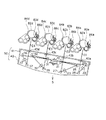
図1は本発明の実施の形態に係る画像形成装置としてタンデム型カラープリンタ100を示す概略断面図、図2はカラープリンタ100に備えられた走査光学ユニットとしての走査式光学装置50及び画像形成部81を示す概略断面図、図3,4は走査式光学装置50に備えられたレーザホルダ部の概略断面図である。
FIG. 1 is a schematic sectional view showing a
まず、カラープリンタ100について説明する。
First, the
カラープリンタ100には、ブラック色の画像を形成する画像形成部81Bkと、シアン色の画像を形成する画像形成部81Cと、マゼンタ色の画像を形成する画像形成部81Mと、イエロー色の画像を形成する画像形成部81Yの4つの画像形成部(画像形成ユニット)81を備えている。そして、これら4つの画像形成部81Bk,81C,81M,81Yは、カラープリンタ100を設置する場合の設置面S(筐体の所定面)に対して、画像形成部81Bkが設置面Sに最も近い状態で傾斜して一列に一定間隔で配置される。
The
このため、画像形成部の占有空間が左右の幅方向や、上下の高さ方向に大型化せず、カラープリンタ100を小型化することができる。
For this reason, the
各画像形成部81Bk,81C,81M,81Yには、それぞれ像担持体としてドラム型の感光体(以下、感光ドラムという)82a,82b,82c,82dが設置されている。ここで、設置面Sに対して画像形成部が傾斜して配置されていることにより、感光ドラムにおいても設置面Sに対して傾斜して配置されることとなる。これは、感光ドラムが、設置面Sからの距離が徐々に小さく又は大きくなるように、設置面Sに対して傾斜して並設されているということもできる。 In each of the image forming units 81Bk, 81C, 81M, and 81Y, drum-type photosensitive members (hereinafter referred to as photosensitive drums) 82a, 82b, 82c, and 82d are installed as image carriers. Here, since the image forming unit is arranged to be inclined with respect to the installation surface S, the photosensitive drum is also arranged to be inclined with respect to the installation surface S. This can also be said that the photosensitive drums are arranged side by side with respect to the installation surface S so that the distance from the installation surface S gradually decreases or increases.
各感光ドラム82a,82b,82c,82dの周囲には、一次帯電器83a,83b,83c,83d、現像装置84a,84b,84c,84d、転写手段としての転写ローラ85a,85b,85c,85d、ドラムクリーナ装置86a,86b,86c,86dがそれぞれ配置されており、一次帯電器83a,83b,83c,83dと現像装置84a,84b,84c,84d間の下方には走査式光学装置50が設置されている。
Around each
各現像装置84a,84b,84c,84dには、それぞれブラックトナー,シアントナー,マゼンタトナー,イエロートナーが収納されている。
Each developing
各感光ドラム82a,82b,82c,82dは、負帯電のOPC感光体でアルミニウム製のドラム基体上に光導電層を有しており、駆動装置(不図示)によって矢印方向(図1における時計回り方向)に所定のプロセススピードで回転駆動される。
Each of the
一次帯電手段としての一次帯電器83a,83b,83c,83dは、帯電バイアス電源(不図示)から印加される帯電バイアスによって各感光ドラム82a,82b,82c,82d表面を負極性の所定電位に均一に帯電する。
現像装置84a,84b,84c,84dは、トナーを内蔵し、それぞれ各感光ドラム82a,82b,82c,82d上に形成される各静電潜像に各色のトナーを付着させてトナー像として現像(可視像化)する。
The developing
転写手段としての転写ローラ85a,85b,85c,85dは、各一次転写ニップ部にて中間転写ベルト87を介して各感光ドラム82a,82b,82c,82dに当接している。
ドラムクリーナ装置86a,86b,86c,86dは、各感光ドラム上で一次転写時の残留した残留トナーを、各感光ドラムから除去するためのクリーニングブレード等で構成されている。
The
中間転写ベルト87は、一対のベルト搬送ローラ88,89間に張架されており、矢印A方向(図1における反時計回り方向)に回転(移動)される。中間転写ベルト87は、ポリカーボネート、ポリエチレンテレフタレート樹脂フィルム、ポリフッ化ビニリデン樹脂フィルム等のような誘電体樹脂によって構成されている。
The
ベルト搬送ローラ88は、中間転写ベルト87を介して二次転写ローラ90と当接して、二次転写部を形成している。中間転写ベルト87の外側でベルト搬送ローラ89近傍には、中間転写ベルト87表面に残った転写残トナーを除去して回収するベルトクリーニング装置91が設置されている。
The belt conveying roller 88 is in contact with the
92はシート状の記録媒体である転写材を格納する給送カセットで、給送カセット92内の転写材は給送ローラ93により1枚ずつ給送され、レジストローラ対94に搬送されると、いったん停止し、前記二次転写部で所定位置にトナー像を転写されるようにタイミングを合わせて搬送が開始される。
92 is a feeding cassette for storing a transfer material which is a sheet-like recording medium. The transfer material in the feeding
二次転写部でトナー像を転写された転写材は定着器95によりトナー像を熱により定着され、搬送ローラ対96、排出ローラ対97により、排出トレイ98上に搬送、排出される。
The transfer material on which the toner image has been transferred in the secondary transfer portion is fixed by heat by the fixing
次に、走査式光学装置50について説明する。
Next, the scanning
走査式光学装置50において、1はレーザホルダで、光源である半導体レーザ(シングルビームレーザ)2,3を鏡筒保持部1a,1bに圧入して保持している。
In the scanning
鏡筒保持部1a,1bは半導体レーザ2,3の光路を互いに副走査方向に所定角度θを持ってポリゴンミラー10近傍で交差するように光軸を傾斜させて設けられており、鏡筒の外形の一部が一体化されている。このため、半導体レーザ2,3の間隔を近接して保持することが可能である。
The
鏡筒保持部1a,1bの先端側には各半導体レーザ2,3に対応する絞り部1c,1dが設けられ、半導体レーザ2,3から射出されたレーザビームを所望の最適なビーム形状に成形している。
鏡筒保持部1a,1bのさらに先端には、絞り部1c,1dを通過した各レーザビームを略平行レーザビームに変換するコリメータレンズ6,7の接着部1e,1fが主走査方向に各2箇所設けられている。
At the further ends of the lens
ここで、コリメータレンズ6,7は照射位置やピントをレーザ光の光学特性を検出しながら調整を行い、位置が決定すると紫外線硬化形の接着剤を紫外線照射することで接着部1e,1fに接着固定される。
Here, the
40は走査式光学装置50の各光学部品を格納する光学ケースであり、光学ケース40の側壁には、レーザホルダ1を位置決めするための嵌合穴部および長穴部が副走査方向に設けられており、レーザホルダ1の鏡筒保持部1a,1bの外形部に設けられた嵌合部を嵌合させて取り付けられるようにしている。
このように、半導体レーザ2,3を保持して光路を形成する鏡筒保持部1a,1bの外形部に設けられた嵌合部を嵌合させて光学ケース40にレーザホルダ1を取り付けているので、半導体レーザ2,3と光学ケース40に格納された各光学部品との位置関係を精度良く保証することができる。
In this manner, the laser holder 1 is attached to the
11はレーザホルダで、レーザホルダ1と同一部品であり、半導体レーザ12,13を鏡筒保持部11a,11bに圧入して保持している。ここで、鏡筒保持部11a,11bは半導体レーザ12,13の光路を互いに副走査方向に所定角度θを持ってポリゴンミラー10近傍で交差するように光軸を傾斜させて設けられており、鏡筒の外形の一部が一体化されている。
鏡筒保持部11a,11bの先端側には各半導体レーザ12,13に対応する絞り部11c,11dが設けられ、半導体レーザ12,13から射出されたレーザビームを所望の最適なビーム形状に成形している。
鏡筒保持部11a,11bのさらに先端には、絞り部11c,11dを通過した各レーザビームを略平行レーザビームに変換するコリメータレンズ16,17の接着部11e,11fが主走査方向に各2箇所設けられている。
At the distal ends of the lens
ここで、コリメータレンズ16,17はコリメータレンズ6,7と同様に、照射位置やピントの調整を行い、接着部11e,11fに接着固定される。
Here, like the
レーザホルダ11の光学ケース40に対する位置決めもレーザホルダ1と同様になされている。このため、半導体レーザ12,13と光学ケース40に格納された各光学部品との位置関係を精度良く保証することができる。
The positioning of the
10は回転多面鏡としてのポリゴンミラーで、不図示のモータを一定速度で回転させることで、半導体レーザから射出されたレーザビームを偏向走査する。ここで、半導体レーザ2,12は下側(本実施の形態では設置面S側)から上側(本実施の形態では感光ドラム側)に向けて副走査方向に角度θを持ってポリゴンミラー10に斜入射されるため、ポリゴンミラー10によって偏向走査される際、副走査方向に角度θを持って上側に射出される。つまり、感光ドラム側のレーザビームとなる。
一方、半導体レーザ3,13は上側から下側に向けて副走査方向に角度θを持ってポリゴンミラー10に斜入射されるため、ポリゴンミラー10によって偏向走査される際、副走査方向に角度θを持って下側に射出される。つまり、設置面S側のレーザビームとなる。
On the other hand, since the
21は第1の結像レンズで、第2の結像レンズ22,23と共に、半導体レーザ2,3から射出されたレーザ光を等速走査および感光ドラム上でスポット結像させるfθレンズであるが、第1の結像レンズ21は半導体レーザ2,3から射出されたレーザビームが互いに異なる角度で入射するためシリンダーレンズで構成しており、副走査方向には、半導体レーザ2のレーザビームに対して配置した第2の結像レンズ22および半導体レーザ3のレーザビームに対して配置した第2の結像レンズ23で結像させる。
Reference numeral 21 denotes a first imaging lens, which is an fθ lens that, together with the
24〜27はそれぞれ、レーザビームを所定の方向へ反射する折り返しミラーである。24は半導体レーザ2のレーザビームに対して配置された折り返しミラーであり、25は半導体レーザ2のレーザビームに対して配置された最終折り返しミラーである。
Reference numerals 24 to 27 denote folding mirrors that reflect the laser beam in a predetermined direction. Reference numeral 24 denotes a folding mirror arranged with respect to the laser beam of the
26は半導体レーザ3のレーザビームに対して配置された分離用折り返しミラーであり、半導体レーザ2のレーザビームと分離する際、半導体レーザ2のレーザビームとの干渉を避けるための面取りを設けている。27は半導体レーザ3のレーザビームに対して配置された最終折り返しミラーである。
そして、設置面Sに最も近く配置された感光ドラム82aに照射される半導体レーザ2のレーザビーム(走査光E1)が、ポリゴンミラー10によって偏向走査されてから折り返しミラー24に到達するまでの光路は、半導体レーザ3のレーザビーム(走査光E2)がポリゴンミラー10によって偏向走査されてから分離用折り返しミラー26に到達するまでの光路に対して感光ドラム側に設けられている。
The optical path from when the laser beam (scanning light E1) of the
ここで、第1の結像レンズ21、第2の結像レンズ22,23、折り返しミラー24〜27は、本発明に係る結像光学手段を構成しており、さらに、折り返しミラー24,26は本発明に係る第1の反射部材を構成し、折り返しミラー25,27は本発明に係る第2の反射部材を構成している。
Here, the first imaging lens 21, the
このように、折り返しミラー24,26でレーザビームを感光ドラムと反対の設置面S側に一旦反射させてから、最終折り返しミラー25,27で感光ドラムに向けて折り返しているため、少ないスペースを有効活用して半導体レーザ2,3のレーザビームを同一の光路長にしながら、走査式光学装置50を感光ドラムに近接配置することができる。
As described above, the laser beam is once reflected by the folding mirrors 24 and 26 toward the installation surface S side opposite to the photosensitive drum and then folded by the final folding mirrors 25 and 27 toward the photosensitive drum. By utilizing the laser beams of the
さらに、ポリゴンミラー10によって偏向走査された後、感光ドラム側のレーザビームである半導体レーザ2のレーザビームを最も設置面Sに近い感光ドラム82aに照射するようにしているため、折り返しミラー24、最終折り返しミラー25の位置は感光ドラム82aに近づけることができるため、走査式光学装置50の設置面S側の突出量が少なくなり、カラープリンタ100を薄型化することができる。
Further, since the laser beam of the
一方、ポリゴンミラー10の反対側には、半導体レーザ12,13に対応した第1の結像レンズ31、第2の結像レンズ32,33、半導体レーザ12のレーザビームに対して配置された折り返しミラー34、最終折り返しミラー35、半導体レーザ13のレーザビームに対して配置された分離用折り返しミラー36、最終折り返しミラー37が配置されている。
On the other hand, on the opposite side of the
そして、設置面Sから最も遠く配置された感光ドラム82dに照射される半導体レーザ13のレーザビーム(走査光E4)が、ポリゴンミラー10によって偏向走査されてから折り返しミラー36に到達するまでの光路は、半導体レーザ12のレーザビーム(走査光E3)がポリゴンミラー10によって偏向走査されてから折り返しミラー34に到達するまでの光路に対して設置面S側に設けられている。
The optical path from when the laser beam (scanning light E4) of the
ここで、第1の結像レンズ31、第2の結像レンズ32,33、折り返しミラー34〜37は、本発明に係る結像光学手段を構成しており、さらに、折り返しミラー34,36は本発明に係る第1の反射部材を構成し、折り返しミラー35,37は本発明に係る第2の反射部材を構成している。
Here, the
このように、折り返しミラー34,36でレーザビームを感光ドラムと反対の設置面S側に一旦反射させてから、最終折り返しミラー35,37で感光ドラムに向けて折り返しているため、少ないスペースを有効活用して半導体レーザ12,13のレーザビームを同一の光路長にしながら、走査式光学装置50を感光ドラムに近接配置することができる。
In this way, the laser beam is once reflected on the installation surface S side opposite to the photosensitive drum by the folding mirrors 34 and 36, and then folded toward the photosensitive drum by the final folding mirrors 35 and 37, so that a small space is effective. The scanning
さらに、ポリゴンミラー10によって偏向走査された後、設置面S側のレーザビームである半導体レーザ13のレーザビームを最も設置面Sから遠い感光ドラム82dに照射するようにしているため、半導体レーザ12のレーザビームはポリゴンミラー10によって偏向走査された後、半導体レーザ13のレーザビームより感光ドラム側にあるため、折り返しミラー34でレーザビームを感光ドラムと反対の設置面S側に一旦反射させる際、折り返しミラー34に半導体レーザ13のレーザビームとの干渉防止の面取りを設ける必要がない。このため、上述した符号21〜27で示す結像光学手段をポリゴンミラー10に対して対称に配置して設けた場合よりも、ローコストにすることができる。
Further, since the laser beam of the
このように、レーザビームが照射されるいずれの方向をも、反射部材26と反射部材24の構成を用いることも考えられるが、その場合には、回転多面鏡に近い第一反射部材26の干渉防止のための面取りを両サイド行う必要があるため、構成が複雑になり、好ましくない。
As described above, the configuration of the reflecting
41は上フタで、光学ケース40に取り付けることで、走査式光学装置50を密封し、走査式光学装置50内に埃やトナー等の進入を防止している。
上フタ41には、各感光ドラム82a,82b,82c,82dに対応した位置にスリット状の開口部が設けられており、透明部材である防塵ガラス43a,43b,43c,43dが取り付けられている。このため、防塵ガラス43a,43b,43c,43dを通して各感光ドラム82a,82b,82c,82dに走査光を露光することが可能であるが、走査式光学装置50内に埃やトナー等の進入を防止することができる。
The
次に、半導体レーザ2,3,12,13から射出されたレーザビームが各感光ドラム82a,82b,82c,82dに走査光E1,E2,E3,E4として露光されるまでの流れを説明する。
Next, the flow until the laser beams emitted from the
半導体レーザ2,3から射出されたレーザビーム(走査光E1,E2)はレーザホルダ1の絞り部1c,1dによってそのレーザビーム断面の大きさが制限され、コリメータレンズ6,7により略平行レーザビームに変換され、不図示のシリンドリカルレンズに入射する。
Laser beams emitted from the
シリンドリカルレンズに入射したレーザビーム(走査光E1,E2)のうち主走査断面内においてはそのままの状態で透過され、副走査断面内においては収束してポリゴンミラー10の同一面にほぼ線像として結像する。この際、副走査方向に角度θを持ってポリゴンミラー10近傍で交差するように斜入射される。
Of the laser beam (scanning light E1, E2) incident on the cylindrical lens, the laser beam is transmitted as it is in the main scanning section, converges in the sub-scanning section, and is converged on the same surface of the
そして、ポリゴンミラー10が回転することで偏向走査しながら、副走査方向に角度θを持って射出される。ポリゴンミラー10から射出された2本のレーザビーム(走査光E1,E2)のうち、半導体レーザ2から射出したレーザビームが不図示のBDセンサに受光される。BDセンサが半導体レーザ2から射出したレーザビームを検知して同期信号を出力し、半導体レーザ2,3による画像端部の走査開始位置のタイミングを調整する。
Then, the
ここで、半導体レーザ2,3が副走査方向に1つのレーザホルダ1に設けられているため、半導体レーザ3による画像端部の走査開始位置のタイミングは半導体レーザ2と同じタイミングとすることができる。タイミング調整されて半導体レーザ2,3から射出されたレーザビームは、第1の結像レンズ21を透過する。
Here, since the
その後、半導体レーザ2から射出したレーザビームは折り返しミラー24により下側に反射された後、第2の結像レンズ22を透過して最終折り返しミラー25によって反射され、防塵ガラス43aを透過して感光ドラム82aに走査光E1として露光される。
Thereafter, the laser beam emitted from the
一方、半導体レーザ3から射出したレーザビームは分離用折り返しミラー26により下側に反射された後、第2の結像レンズ23を透過して最終折り返しミラー27によって反射され、防塵ガラス43bを透過して感光ドラム82bに走査光E2として露光される。
On the other hand, the laser beam emitted from the
また、半導体レーザ12,13から射出されたレーザビーム(走査光E3,E4)はレーザホルダ11の絞り部11c,11dによってそのレーザビーム断面の大きさが制限され、コリメータレンズ16,17により略平行レーザビームに変換され、不図示のシリンドリカルレンズに入射する。
The laser beams (scanning lights E3 and E4) emitted from the
シリンドリカルレンズに入射したレーザビーム(走査光E3,E4)のうち主走査断面内においてはそのままの状態で透過され、副走査断面内においては収束してポリゴンミラー10の同一面にほぼ線像として結像する。この際、副走査方向に角度θを持ってポリゴンミラー10近傍で交差するように斜入射される。
Of the laser beam (scanning beams E3 and E4) incident on the cylindrical lens, the laser beam is transmitted as it is in the main scanning section, converges in the sub-scanning section, and is converged on the same surface of the
そして、ポリゴンミラー10が回転することで偏向走査しながら、副走査方向に角度θを持って射出される。ポリゴンミラー10から射出された2本のレーザビーム(走査光E3,E4)のうち、半導体レーザ12から射出してポリゴンミラー10に反射されたレーザビームが不図示のBDセンサに受光される。BDセンサが半導体レーザ12から射出したレーザビームを検知して同期信号を出力し、半導体レーザ12,13による画像端部の走査開始位置のタイミングを調整する。
Then, the
ここで、半導体レーザ12,13が副走査方向に1つのレーザホルダ11に設けられているため、半導体レーザ13による画像端部の走査開始位置のタイミングは半導体レーザ12と同じタイミングとすることができる。タイミング調整されて半導体レーザ12,13から射出されたレーザビームは、第1の結像レンズ31を透過する。
Here, since the
その後、半導体レーザ12から射出したレーザビームは分離用折り返しミラー34により下側に反射された後、第2の結像レンズ32を透過して最終折り返しミラー35によって反射され、防塵ガラス43cを透過して感光ドラム82cに走査光E3として露光される。
Thereafter, the laser beam emitted from the
一方、半導体レーザ13から射出したレーザビームは折り返しミラー36により下側に反射された後、第2の結像レンズ33を透過して最終折り返しミラー37によって反射され、防塵ガラス43dを透過して感光ドラム82dに走査光E4として露光される。
On the other hand, the laser beam emitted from the
次に、カラープリンタ100において画像形成を行う場合の動作について説明する。
Next, an operation when image formation is performed in the
プリントスタートの信号が入力されると、画像情報に基づいて走査式光学装置50から各感光ドラム82a,82b,82c,82dにレーザビームが走査光として露光される。レーザビームが露光されるまでの説明は、先述の半導体レーザ2,3,12,13から射出されたレーザビームが各感光ドラム82a,82b,82c,82dに走査光E1,E2,E3,E4として露光されるまでの流れの説明と同様のため省略する。
When a print start signal is input, a laser beam is exposed as scanning light from the scanning
画像形成は、各感光ドラム82a,82b,82c,82dが露光されることで、一次帯電器83a,83b,83c,83dにより帯電された各感光ドラム82a,82b,82c,82d上に静電潜像を形成する。
In image formation, the
その後、現像装置84a,84b,84c,84d内で摩擦帯電された各色のトナーを前記静電潜像に付着させることで各感光ドラム82a,82b,82c,82d上にトナー像が形成され、前記トナー像は各感光ドラム82a,82b,82c,82d上から各一次転写ニップ部にて中間転写ベルト87上に転写される。
Thereafter, toner of each color frictionally charged in the developing
一方、給送カセット92から給送ローラ93により転写材が1枚ずつ給送され、レジストローラ対94に搬送されると、いったん停止し、前記二次転写部で所定位置にトナー像を転写されるようにタイミングを合わせて搬送が開始される。
On the other hand, when the transfer material is fed one by one by the
二次転写部では、中間転写ベルト87上から転写材にトナー像を再度転写することで画像が転写材に形成される。画像が形成された転写材は定着器95によりトナー像を熱により定着され、搬送ローラ対96、排出ローラ対97により、排出トレイ98上に搬送、排出される。
In the secondary transfer portion, the toner image is transferred again from the
以上、説明したように、1つのポリゴンミラー10で複数の半導体レーザ2,3,12,13から射出されたレーザ光を同時に偏向走査して、複数の感光ドラム82a,82b,82c,82dに照射して露光を行う際、カラープリンタ100の設置面Sに最も近い
感光ドラム82aへのレーザビームが、ポリゴンミラー10での偏向後、感光ドラム側を通るように走査することで、折り返しミラー24および最終折り返しミラー25を感光ドラム82aに近づけて配置できるため、走査式光学装置50の設置面S側への突出を抑え、薄型化した画像形成装置を提供することが可能となる。
As described above, the laser light emitted from the plurality of
さらに、ポリゴンミラー10によって偏向走査された後、設置面S側のレーザビームである半導体レーザ13のレーザビームを最も設置面Sから遠い感光ドラム82dに照射するようにしているため、半導体レーザ12のレーザビームはポリゴンミラー10によって偏向走査された後、半導体レーザ13のレーザビームより感光ドラム側にあるため、折り返しミラー34でレーザビームを感光ドラムと反対の設置面S側に一旦反射させる際、折り返しミラー34に半導体レーザ13のレーザビームとの干渉防止の面取りを設ける必要がない。このため、21〜27の結像光学手段をポリゴンミラー10に対して対称に配置した場合より、ローコストにすることができる。
Further, since the laser beam of the
さらに、半導体レーザ2,3および、半導体レーザ12,13の光路を互いに副走査方向に所定角度θを持ってポリゴンミラー10近傍で交差するように光軸を傾斜させて設けているため、カラープリンタ100の設置面Sに最も近い感光ドラム82aへのレーザビームが、ポリゴンミラー10での偏向後、感光ドラム側に近づいて行くため、折り返しミラー24および最終折り返しミラー25を感光ドラム82aにより一層近づけて配置できるため、走査式光学装置50の設置面S側への突出を抑え、より薄型化した画像形成装置を提供することが可能となる。
Further, since the optical paths of the
ここで、半導体レーザ2,3,12,13は1つの筐体に1つの発光点を有するシングルレーザを用いているが、1つの筐体に複数の発光点を有する半導体レーザを用いても良く、その場合は感光ドラムを操作する走査線本数が比例して多くなるため、さらに高速な書き込みに適することができる。
Here, the
また、本実施の形態においては、半導体レーザ2,3および、半導体レーザ12,13の光路を互いに副走査方向に所定角度θを持ってポリゴンミラー10近傍で交差するように光軸を傾斜させて設けた斜入射の構成をとっているが、副走査方向に角度を持たず、平行に入射する構成をとっても良い。ただし、その場合は、カラープリンタ100の設置面Sに最も近い感光ドラム82aへのレーザビームが、ポリゴンミラー10での偏向後、感光ドラムと平行に走査されて行くので、斜入射の構成の方が、折り返しミラー24および最終折り返しミラー25を感光ドラム82aにより一層近づけて配置できるため、走査式光学装置50の設置面S側への突出を抑え、より薄型化した画像形成装置を提供することが可能となる。
In the present embodiment, the optical axes of the
また、実施の形態では、下面露光の構成であったが、像担持体の上面に露光ユニットがある構成の上面露光の構成であっても問題ない。 In the embodiment, the configuration of the bottom exposure is used. However, there is no problem even if the configuration of the top exposure is such that the exposure unit is on the top surface of the image carrier.
また、図5には、本実施の形態とは第一の結像レンズの位置が異なる構成を示すものである。このように結像レンズを像担持体間(82aと82b間、82cと82d間)に設けることで82bと82c間のドラム間距離を小さくすることができる。このような、光学ユニットであっても、本発明の構成を用いても問題ない。 FIG. 5 shows a configuration in which the position of the first imaging lens is different from that of the present embodiment. Thus, by providing the imaging lens between the image carriers (between 82a and 82b, between 82c and 82d), the distance between the drums between 82b and 82c can be reduced. Even if it is such an optical unit, even if it uses the structure of this invention, there is no problem.
1,11 レーザホルダ
2,3,12,13 半導体レーザ
21,31 第1の結像レンズ
22,23,32,33 第2の結像レンズ
24〜27,34〜37 折り返しミラー
40 光学ケース
50 走査式光学装置
81Bk,81C,81M,81Y 画像形成部
82a,82b,82c,82d 感光ドラム
100 カラープリンタ
DESCRIPTION OF
Claims (8)
前記複数の像担持体と画像形成装置の底面との間に設けられる光学ユニットであって、前記複数の像担持体のうちの第1の像担持体を露光するための第1のレーザビームを出射する第1の光源と、鉛直方向において前記第1の像担持体より上側に設けられる第2の像担持体を露光するための第2のレーザビームを出射する第2の光源と、前記第1のレーザビームと前記第2のレーザビームとを同一の反射面で偏向する回転多面鏡と、前記回転多面鏡によって偏向された前記第1のレーザビームを前記第1の像担持体から遠ざける方向に反射する第1の反射ミラーと、前記第1の反射ミラーが反射した前記第1のレーザビームを前記第1の像担持体に導く第2の反射ミラーと、前記回転多面鏡によって偏向された前記第2のレーザビームを前記第2の像担持体から遠ざける方向に反射する第3の反射ミラーと、前記第3の反射ミラーが反射した前記第2のレーザビームを第2の像担持体に導く第4の反射ミラーと、を有する光学ユニットと、
を備え、
前記第2の反射ミラーから前記第1の像担持体までの前記第1のレーザビームの光路を前記第4の反射ミラーから前記第2の像担持体までの前記第2のレーザビームの光路よりも短くするために、前記第1の光源、前記第2の光源、前記第1の反射ミラー、及び前記第3の反射ミラーは、前記回転多面鏡から前記第1の反射ミラーに向かう前記第1のレーザビームが前記回転多面鏡から前記第3の反射ミラーに向かう第2のレーザビームに対して前記像担持体が配置される側の光路をとるように前記光学ユニットにそれぞれ配置されることを特徴とする画像形成装置。 A plurality of image carriers arranged side by side with respect to the horizontal direction ;
An optical unit that is provided between the bottom of the plurality of image carrier and the image forming apparatus, a first laser beam for exposing the first image bearing member of the plurality of image bearing members A second light source that emits a second laser beam for exposing a second image carrier that is provided above the first image carrier in the vertical direction; the first laser beam and the second rotation polygon mirror and the first laser beam the first image deflected me by the rotary polygon mirror and a laser beam is deflected by the same reflecting surface A first reflection mirror that reflects in a direction away from the carrier; a second reflection mirror that guides the first laser beam reflected by the first reflection mirror to the first image carrier; The second laser beam deflected by a mirror And a third reflecting mirror for reflecting in the direction away from the second image bearing member, and a fourth reflecting mirror for guiding the third said second laser beam reflecting mirror is reflected in the second image bearing member, a a light Science unit having,
Equipped with a,
From the optical path of the first laser beam from the second reflection mirror to the first image carrier, from the optical path of the second laser beam from the fourth reflection mirror to the second image carrier. The first light source, the second light source, the first reflection mirror, and the third reflection mirror are also directed to the first reflection mirror from the rotary polygon mirror to the first reflection mirror. Are arranged in the optical unit so as to take an optical path on the side where the image carrier is arranged with respect to the second laser beam directed from the rotary polygon mirror to the third reflecting mirror. An image forming apparatus.
の像担持体よりも前記上側に設けられる第4の像担持体を露光するための第4のレーザビームを出射する第4の光源と、前記回転多面鏡によって偏向された前記第3のレーザビームを前記第3の像担持体から遠ざける方向に反射する第5の反射ミラーと、前記第5の反射ミラーが反射した前記第3のレーザビームを前記第3の像担持体に導く第6の反射ミラーと、前記回転多面鏡によって偏向された前記第4のレーザビームを前記第4の像担持体から遠ざける方向に反射する第7の反射ミラーと、前記第7の反射ミラーが反射した前記第4のレーザビームを第4の像担持体に導く第8の反射ミラーと、を有し、
前記第3のレーザビーム及び前記第4のレーザビームは、前記回転多面鏡の同一の反射面によって偏向され、かつ前記第1のレーザビーム及び前記第2のレーザビームとは前記回転多面鏡に対して反対方向に偏向され、
前記第3の光源、前記第4の光源、前記第5の反射ミラー、及び前記第7の反射ミラーは、前記回転多面鏡から前記第5の反射ミラーに向かう第3のレーザビームが前記回転多面鏡から前記第7の反射ミラーに向かう第4のレーザビームに対して前記像担持体が配置される側の光路をとるように前記光学ユニットにそれぞれ配置されることを特徴とする請求項1に記載の画像形成装置。 The optical unit includes a third light source that emits a third laser beam for exposing a third image carrier that is provided above the second image carrier in the vertical direction, and the third light source.
A fourth light source that emits a fourth laser beam for exposing a fourth image carrier provided above the image carrier, and the third laser beam deflected by the rotary polygon mirror Is reflected in a direction away from the third image carrier, and a sixth reflection for guiding the third laser beam reflected by the fifth reflection mirror to the third image carrier. A mirror, a seventh reflection mirror that reflects the fourth laser beam deflected by the rotary polygon mirror in a direction away from the fourth image carrier, and the fourth reflection reflected by the seventh reflection mirror. And an eighth reflecting mirror for guiding the laser beam to the fourth image carrier,
The third laser beam and the fourth laser beam are deflected by the same reflecting surface of the rotary polygon mirror, and the first laser beam and the second laser beam are different from the rotary polygon mirror. Is deflected in the opposite direction,
In the third light source, the fourth light source, the fifth reflection mirror, and the seventh reflection mirror, the third laser beam directed from the rotary polygon mirror to the fifth reflection mirror is the rotary polygon. 2. The optical unit according to claim 1 , wherein the optical unit is arranged to take an optical path on a side where the image carrier is arranged with respect to a fourth laser beam directed from the mirror toward the seventh reflection mirror. The image forming apparatus described.
Priority Applications (2)
| Application Number | Priority Date | Filing Date | Title |
|---|---|---|---|
| JP2004329854A JP4654004B2 (en) | 2004-11-12 | 2004-11-12 | Image forming apparatus |
| US11/270,567 US7446794B2 (en) | 2004-11-12 | 2005-11-10 | Image forming apparatus |
Applications Claiming Priority (1)
| Application Number | Priority Date | Filing Date | Title |
|---|---|---|---|
| JP2004329854A JP4654004B2 (en) | 2004-11-12 | 2004-11-12 | Image forming apparatus |
Publications (3)
| Publication Number | Publication Date |
|---|---|
| JP2006139152A JP2006139152A (en) | 2006-06-01 |
| JP2006139152A5 JP2006139152A5 (en) | 2009-10-15 |
| JP4654004B2 true JP4654004B2 (en) | 2011-03-16 |
Family
ID=36385828
Family Applications (1)
| Application Number | Title | Priority Date | Filing Date |
|---|---|---|---|
| JP2004329854A Expired - Fee Related JP4654004B2 (en) | 2004-11-12 | 2004-11-12 | Image forming apparatus |
Country Status (2)
| Country | Link |
|---|---|
| US (1) | US7446794B2 (en) |
| JP (1) | JP4654004B2 (en) |
Families Citing this family (7)
| Publication number | Priority date | Publication date | Assignee | Title |
|---|---|---|---|---|
| JP4654004B2 (en) | 2004-11-12 | 2011-03-16 | キヤノン株式会社 | Image forming apparatus |
| JP2006313208A (en) * | 2005-05-06 | 2006-11-16 | Canon Inc | Image forming apparatus and its control method |
| TWI268867B (en) * | 2006-01-27 | 2006-12-21 | E Pin Optical Industry Co Ltd | Multi-beam tandem laser scanning unit |
| CN102081231B (en) | 2009-11-30 | 2014-11-19 | 京瓷办公信息系统株式会社 | Optical scanning apparatus and image forming apparatus |
| JP5090429B2 (en) * | 2009-11-30 | 2012-12-05 | 京セラドキュメントソリューションズ株式会社 | Color image forming apparatus |
| JP6147042B2 (en) | 2012-04-25 | 2017-06-14 | キヤノン株式会社 | Image forming apparatus |
| JP6202940B2 (en) | 2013-08-23 | 2017-09-27 | キヤノン株式会社 | Light beam emitting device, optical scanning device, and image forming apparatus |
Citations (4)
| Publication number | Priority date | Publication date | Assignee | Title |
|---|---|---|---|---|
| JP2000180750A (en) * | 1998-12-18 | 2000-06-30 | Fuji Xerox Co Ltd | Optical scanner |
| JP2002091123A (en) * | 2000-07-14 | 2002-03-27 | Ricoh Co Ltd | Color image forming device and toner replenishing device |
| JP2003156896A (en) * | 2001-11-19 | 2003-05-30 | Seiko Epson Corp | Image forming device |
| JP2004177525A (en) * | 2002-11-25 | 2004-06-24 | Ricoh Co Ltd | Image forming apparatus and process cartridge |
Family Cites Families (9)
| Publication number | Priority date | Publication date | Assignee | Title |
|---|---|---|---|---|
| JP2878181B2 (en) * | 1996-04-18 | 1999-04-05 | 新潟日本電気株式会社 | Color image forming equipment |
| JP3287319B2 (en) * | 1998-10-16 | 2002-06-04 | 富士ゼロックス株式会社 | Optical scanning device, scanning lens, and image forming device |
| US20030112316A1 (en) * | 2001-11-27 | 2003-06-19 | Seiko Epson Corporation | Image forming apparatus |
| KR100846775B1 (en) * | 2002-05-10 | 2008-07-16 | 삼성전자주식회사 | Color laser printer |
| JP2004021133A (en) * | 2002-06-20 | 2004-01-22 | Canon Inc | Scanning optical device |
| JP4136729B2 (en) * | 2003-03-07 | 2008-08-20 | キヤノン株式会社 | Image forming apparatus |
| JP4027293B2 (en) * | 2003-09-24 | 2007-12-26 | キヤノン株式会社 | Scanning optical device |
| JP4654004B2 (en) | 2004-11-12 | 2011-03-16 | キヤノン株式会社 | Image forming apparatus |
| JP2006313208A (en) * | 2005-05-06 | 2006-11-16 | Canon Inc | Image forming apparatus and its control method |
-
2004
- 2004-11-12 JP JP2004329854A patent/JP4654004B2/en not_active Expired - Fee Related
-
2005
- 2005-11-10 US US11/270,567 patent/US7446794B2/en active Active
Patent Citations (4)
| Publication number | Priority date | Publication date | Assignee | Title |
|---|---|---|---|---|
| JP2000180750A (en) * | 1998-12-18 | 2000-06-30 | Fuji Xerox Co Ltd | Optical scanner |
| JP2002091123A (en) * | 2000-07-14 | 2002-03-27 | Ricoh Co Ltd | Color image forming device and toner replenishing device |
| JP2003156896A (en) * | 2001-11-19 | 2003-05-30 | Seiko Epson Corp | Image forming device |
| JP2004177525A (en) * | 2002-11-25 | 2004-06-24 | Ricoh Co Ltd | Image forming apparatus and process cartridge |
Also Published As
| Publication number | Publication date |
|---|---|
| JP2006139152A (en) | 2006-06-01 |
| US20060103716A1 (en) | 2006-05-18 |
| US7446794B2 (en) | 2008-11-04 |
Similar Documents
| Publication | Publication Date | Title |
|---|---|---|
| JP5013652B2 (en) | Scanning optical device | |
| JP2006267398A (en) | Scanning optical apparatus and image forming apparatus | |
| US20060055769A1 (en) | Optical writing apparatus and image forming apparatus | |
| JP6147042B2 (en) | Image forming apparatus | |
| US7697182B2 (en) | Scanning optical apparatus and image forming apparatus wherein a route of the second laser beam reflected by the first rotating polygon mirror and a route of the third laser beam reflected by the second rotating polygon mirror cross each other in the optical box | |
| US8542263B2 (en) | Mounting structure of a mounted component, light scanning device, and image forming apparatus | |
| JP2006323159A (en) | Optical scanner and image forming apparatus | |
| US7446794B2 (en) | Image forming apparatus | |
| US7630111B2 (en) | Optical scanning apparatus and image forming apparatus | |
| JP4921024B2 (en) | Image forming apparatus | |
| JP4818070B2 (en) | Scanning optical apparatus and image forming apparatus | |
| JP2006337514A (en) | Optical scanner and image forming apparatus | |
| JP2011048085A (en) | Scanning optical apparatus and electrophotographic image forming apparatus | |
| JP2008112041A5 (en) | ||
| JP4884035B2 (en) | Optical writing device | |
| JP5494281B2 (en) | Optical scanning apparatus and image forming apparatus | |
| JP5207593B2 (en) | Scanning optical apparatus, image forming apparatus, and scanning line adjustment method for scanning optical apparatus | |
| JP2005091966A (en) | Optical scanner and color image forming apparatus using it | |
| JP2006337515A (en) | Optical scanner and image forming apparatus | |
| JP2001296715A (en) | Tandem type color image forming device | |
| JP2010281869A (en) | Light beam scanning optical system, optical scanning device and image forming device | |
| JP2003140075A (en) | Scanning optical device and image forming device | |
| JP2024049733A (en) | Optical scanning device and image forming device | |
| JP4476192B2 (en) | Lens unit adjustment mechanism, optical scanning device and image forming apparatus provided with lens unit adjustment mechanism | |
| JP2024049735A (en) | Optical scanning device and image forming device |
Legal Events
| Date | Code | Title | Description |
|---|---|---|---|
| A621 | Written request for application examination |
Free format text: JAPANESE INTERMEDIATE CODE: A621 Effective date: 20071109 |
|
| A521 | Request for written amendment filed |
Free format text: JAPANESE INTERMEDIATE CODE: A523 Effective date: 20090902 |
|
| A131 | Notification of reasons for refusal |
Free format text: JAPANESE INTERMEDIATE CODE: A131 Effective date: 20100615 |
|
| A521 | Request for written amendment filed |
Free format text: JAPANESE INTERMEDIATE CODE: A523 Effective date: 20100810 |
|
| TRDD | Decision of grant or rejection written | ||
| A01 | Written decision to grant a patent or to grant a registration (utility model) |
Free format text: JAPANESE INTERMEDIATE CODE: A01 Effective date: 20101214 |
|
| A01 | Written decision to grant a patent or to grant a registration (utility model) |
Free format text: JAPANESE INTERMEDIATE CODE: A01 |
|
| A61 | First payment of annual fees (during grant procedure) |
Free format text: JAPANESE INTERMEDIATE CODE: A61 Effective date: 20101220 |
|
| R150 | Certificate of patent or registration of utility model |
Free format text: JAPANESE INTERMEDIATE CODE: R150 |
|
| FPAY | Renewal fee payment (event date is renewal date of database) |
Free format text: PAYMENT UNTIL: 20131224 Year of fee payment: 3 |
|
| LAPS | Cancellation because of no payment of annual fees |