JP4652103B2 - Vehicle steering system - Google Patents
Vehicle steering system Download PDFInfo
- Publication number
- JP4652103B2 JP4652103B2 JP2005108533A JP2005108533A JP4652103B2 JP 4652103 B2 JP4652103 B2 JP 4652103B2 JP 2005108533 A JP2005108533 A JP 2005108533A JP 2005108533 A JP2005108533 A JP 2005108533A JP 4652103 B2 JP4652103 B2 JP 4652103B2
- Authority
- JP
- Japan
- Prior art keywords
- steering
- operation amount
- vehicle speed
- maximum
- wheel
- Prior art date
- Legal status (The legal status is an assumption and is not a legal conclusion. Google has not performed a legal analysis and makes no representation as to the accuracy of the status listed.)
- Expired - Fee Related
Links
Images


Landscapes
- Steering Control In Accordance With Driving Conditions (AREA)
- Power Steering Mechanism (AREA)
Description
この発明は、運転者が操作を行う操作子と転舵輪を転舵する転舵アクチュエータとが機械的に切り離された所謂ステア・バイ・ワイヤ式の車両用操舵装置に関するものである。 The present invention relates to a so-called steer-by-wire vehicle steering apparatus in which an operator operated by a driver and a steering actuator that steers a steered wheel are mechanically separated.
ステア・バイ・ワイヤ式の車両用操舵装置においては、運転者がステアリングホイールを操作したときに適切な操舵反力を与えるための反力アクチュエータと、運転者のステアリングホイールの操作に応じて転舵輪を転舵するための転舵アクチュエータとを備えており、両アクチュエータをそれぞれ独立に制御している。 In a steer-by-wire vehicle steering system, a reaction force actuator for applying an appropriate steering reaction force when the driver operates the steering wheel, and a steered wheel according to the driver's operation of the steering wheel And a steering actuator for steering the vehicle, and both actuators are independently controlled.
このステア・バイ・ワイヤ式の操舵装置では、ステアリングホイールの操作角と目標転舵角との比(以下、ステアリングレシオと称す)を可変にすることが可能であり、例えば、車速が高くなるにしたがってステアリングレシオを徐々に低減する制御方法が知られている。このように車速に応じてステアリングレシオを可変制御すると、低速時にはステアリングホイールの操作量が少なくて転舵輪を大きく転舵させることができ、また、高速時には操舵が安定するというメリットがある。また、このようにステアリングレシオを可変制御すると、ステアリングラックがラックエンドに達して転舵輪が最大転舵したときのステアリングホイールの回転角(最大回転角)は車速に応じて変化することとなり、車速が高いほど大きくなる。 In this steer-by-wire steering device, the ratio of the steering wheel operation angle to the target turning angle (hereinafter referred to as the steering ratio) can be made variable, for example, the vehicle speed increases. Therefore, a control method for gradually reducing the steering ratio is known. If the steering ratio is variably controlled according to the vehicle speed in this manner, there is an advantage that the steered wheel can be steered greatly at a low speed because the operation amount of the steering wheel is small, and the steering is stable at a high speed. In addition, when the steering ratio is variably controlled in this manner, the rotation angle (maximum rotation angle) of the steering wheel when the steering rack reaches the rack end and the steered wheels are steered to the maximum changes according to the vehicle speed. The higher the value, the larger.
ただし、ステア・バイ・ワイヤ式の操舵装置では、ステアリングホイールと転舵機構が機械的に切り離されているため、転舵輪が最大転舵になってもステアリングホイールはさらに切り増しが可能であり、このような状態になったときには、運転者にこれ以上は転舵輪を転舵させることができないことを認識させる必要がある。
この最大転舵を認識させる従来の手法として、最大転舵に近づいたときに反力アクチュエータの推力を急激に立ち上げてステアリングホイールをそれ以上切り増しすることができないようにする方法が知られている(例えば、特許文献1参照)。
As a conventional method for recognizing the maximum turning, there is a known method of suddenly raising the thrust of the reaction force actuator so that the steering wheel cannot be further increased when approaching the maximum turning. (For example, refer to Patent Document 1).
ところで、車両では、運転者に対する衝突時の衝撃軽減装置としてステアリングホイール内に所謂エアバッグを収納する場合があり、この場合にはエアバッグ作動用電気信号を通信するためのケーブルリール電気信号線を中空軸からなるステアリングシャフトに挿通して配線している。ケーブルリール電気信号線は、ステアリングホイールの回転による捩れを許容できるように螺旋状をなしているが、その許容範囲にも限界があるため、ステアリングホイールの最大回転角に基づいてケーブルリール電気信号線の仕様を設定している。したがって、従来は、最大回転角が一番大きくなる高速時における最大回転角に基づいてケーブルリール電気信号線の仕様を設定せざるを得ず、その結果、ケーブルリール電気信号線の寸法や重量が大きくなる。 By the way, in a vehicle, there is a case where a so-called airbag is stored in a steering wheel as an impact reducing device at the time of a collision with a driver. In this case, a cable reel electrical signal line for communicating an airbag actuation electrical signal is provided. The wiring is inserted through the steering shaft consisting of a hollow shaft. The cable reel electrical signal line has a spiral shape so as to allow twisting due to the rotation of the steering wheel. However, since the allowable range is limited, the cable reel electrical signal line is based on the maximum rotation angle of the steering wheel. The specifications are set. Therefore, conventionally, the specification of the cable reel electric signal line has to be set based on the maximum rotation angle at high speed at which the maximum rotation angle is the largest, and as a result, the size and weight of the cable reel electric signal line are reduced. growing.
また、反力アクチュエータの推力を急激に立ち上げて最大転舵を認識させる方法では、最大転舵を認識させるときに必要な推力が、通常操舵時に必要となるアクチュエータ生成反力に比べて大きくなり、最大転舵認識のために反力アクチュエータの高出力化が必要になり、アクチュエータが大型化する。
そこで、この発明は、ケーブルリール電気信号線などの寸法縮小化や軽量化が可能な車両用操舵装置を提供するものである。
また、この発明は、反力アクチュエータを大型化することなく最大転舵を容易に認識することができる車両用操舵装置を提供するものである。
In addition, in the method of recognizing the maximum turning by suddenly raising the thrust of the reaction force actuator, the thrust required to recognize the maximum turning is greater than the reaction force generated by the actuator required during normal steering. In order to recognize the maximum turning, it is necessary to increase the output of the reaction force actuator, which increases the size of the actuator.
Accordingly, the present invention provides a vehicle steering apparatus capable of reducing the size and weight of cable reel electrical signal lines and the like.
The present invention also provides a vehicle steering apparatus that can easily recognize the maximum steering without increasing the size of the reaction force actuator.
上記課題を解決するために、請求項1に係る発明は、運転者が操作を行う操作子(例えば、後述する実施例におけるステアリングホイール2)と、前記操作子と機械的に分離されている転舵輪(例えば、後述する実施例における車輪6)と、前記転舵輪を転舵する転舵アクチュエータ(例えば、後述する実施例におけるステアリングモータ10)と、前記操作子の操作量(操作角)を検出する操作量検出手段(例えば、後述する実施例における操作角センサ3)と、車速を検出する車速検出手段(例えば、後述する実施例における車速センサ11)と、前記操作量検出手段により検出した操作量と前記車速検出手段により検出した車速に応じて前記転舵アクチュエータを制御する転舵アクチュエータ制御手段(例えば、後述する実施例における制御装置13)と、を備え、前記操作子の操作量に対する前記転舵輪の転舵量の比が、車速が大きくなるにしたがって小さくなるように制御され、且つ、前記転舵輪が最大転舵となるときの前記操作子の操作量である最大操作量(最大回転角)を、車速にかかわらず一定とし、前記操作子の操作量が大きくなるにしたがって、前記操作子の操作量に対する前記転舵輪の転舵量の比の車速に応じた変化の幅が小さくなることを特徴とする車両用操舵装置(例えば、後述する実施例における車両用操舵装置1)である。
このように構成することにより、操作子の操作量に対する転舵輪の転舵量の比が、車速が大きくなるにしたがって小さくなるように制御されるので、低速時には操作子の操作量が少なくて転舵輪を大きく転舵させることができ、一方、高速時には操舵安定性を向上させることができる。また、転舵輪が最大転舵となるときの操作子の操作量である最大操作量(最大回転角)を、車速にかかわらず一定としたので、最大操作量を設計条件や仕様設定条件の一つとして必要な機器の設計等が容易になる。
In order to solve the above-described problems, an invention according to claim 1 is directed to an operator (for example, a steering wheel 2 in an embodiment described later) that is operated by a driver, and a roller that is mechanically separated from the operator. A steering wheel (for example, a wheel 6 in an embodiment to be described later), a steering actuator for steering the steered wheel (for example, a
With this configuration, the ratio of the steered wheel steered amount to the steered wheel manipulated variable is controlled to decrease as the vehicle speed increases. The steered wheel can be steered greatly, while the steering stability can be improved at high speeds. In addition, since the maximum operation amount (maximum rotation angle), which is the operation amount of the operator when the steered wheels are at maximum steering, is constant regardless of the vehicle speed, the maximum operation amount is one of the design conditions and specification setting conditions. design of equipment readily ing required as One.
請求項2に係る発明は、請求項1に記載の発明において、前記操作子に対する操作量が最大操作量となったときに係止して操作量が前記最大操作量以上に増大するのを阻止するストッパ機構(例えば、後述する実施例におけるストッパ機構20)を備えることを特徴とする。
このように構成することにより、操作子が最大操作量以上に過操作されるのを確実に防止することができる。また、運転者に最大転舵を認識させるための反力制御が不要になるので、反力アクチュエータを小型・軽量化することができる。
According to a second aspect of the present invention, in the first aspect of the present invention, when the operation amount with respect to the operation element becomes a maximum operation amount, the operation amount is prevented and the operation amount is prevented from increasing beyond the maximum operation amount. And a stopper mechanism (for example, a
By configuring in this way, it is possible to reliably prevent the operation element from being excessively operated beyond the maximum operation amount. Further, since the reaction force control for causing the driver to recognize the maximum steering is not required, the reaction force actuator can be reduced in size and weight.
請求項1に係る発明によれば、低速時には操作子の操作量が少なくて転舵輪を大きく転舵させることができ、一方、高速時には操舵安定性を向上させることができる。また、最大操作量を設計条件や仕様設定条件の一つとして必要な機器の設計等が容易になる。
請求項2に係る発明によれば、操作子が最大操作量以上に過操作されるのを確実に防止することができるとともに、反力アクチュエータを小型・軽量化することができる。
According to the first aspect of the present invention, the steered wheel can be steered greatly with a small amount of operation of the operator at low speeds, while the steering stability can be improved at high speeds. In addition, it becomes easy to design a device that requires the maximum operation amount as one of design conditions and specification setting conditions.
According to the second aspect of the present invention, it is possible to reliably prevent the operation element from being excessively operated beyond the maximum operation amount, and to reduce the size and weight of the reaction force actuator.
以下、この発明に係る車両用操舵装置の一実施例を図1〜図4の図面を参照して説明する。
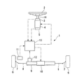
この車両用操舵装置1は、図1に示すように、運転者により操作されるステアリングホイール(操作子)2と、ステアリングホイール2に連結されて同期回転する中空軸からなるステアリングシャフト14と、ステアリングホイール2の操作角(操作量)を検出する操作角センサ(操作量検出手段)3と、ステアリングシャフト14を介してステアリングホイール2に操作反力を付与する反力モータ(反力アクチュエータ)4と、ステアリングシャフト14に作用する操作トルクを検出する操作トルクセンサ5と、左右の車輪(転舵輪)6にナックルアーム7及びタイロッド8を介して連結されたラック軸9と、ラック軸9を軸方向に駆動して車輪6を転舵するステアリングモータ(転舵アクチュエータ)10と、車速を検出する車速センサ(車速検出手段)11と、ラック軸9の軸方向位置から車輪6の転舵角を検出する転舵角センサ(転舵角検出手段)12と、反力モータ4及びステアリングモータ10を制御する制御装置(転舵アクチュエ−タ制御手段)13とを備えている。
Hereinafter, an embodiment of a vehicle steering apparatus according to the present invention will be described with reference to the drawings of FIGS.
As shown in FIG. 1, the vehicle steering apparatus 1 includes a steering wheel (operator) 2 that is operated by a driver, a
この操舵装置1において、反力モータ4とステアリングモータ10は制御装置13によって個別に制御される。
詳述すると、制御装置13は、操作角センサ3からのステアリングホイール2の操作方向(回転方向)を含めた操作角信号と、車速センサ11からの車速信号とに基づいて目標転舵角を設定し、この目標転舵角に転舵角センサ12の出力値、つまり、車輪6の実転舵角が一致するようにステアリングモータ10への供給電力を制御する。これにより、ステアリングホイール2に運転者が与えた操作角(操作量)に対し、その時の車速を加味した最適な車輪6の転舵角が決定される。
In the steering device 1, the reaction force motor 4 and the
Specifically, the
また、制御装置13は、車速センサ11からの車速信号,転舵角センサ12からの転舵角信号等に基づいて目標操作反力を設定し、この目標操作反力に操作トルクセンサ5の出力値(つまり、実操作トルク)が一致するように反力モータ4への供給電力を制御する。これにより、運転者によるステアリングホイール2の操作方向とは逆方向の操作反力がステアリングホイール2に加えられ、ステアリングホイール2と車輪6との間に、あたかもトーションバーが存在するかのような操舵フィーリングを得ることができる。
The
ところで、この操舵装置1では、ステアリングホイール2の操作角と目標転舵角との比、すなわちステアリングレシオを可変制御しており、車速が高くなるにしたがってステアリングレシオが徐々に低減するように、制御装置13によってステアリングモータ10の制御を行っている。これにより、低速時にはステアリングホイールの操作量が少なくて転舵輪を大きく転舵させることができ、また、高速時の操舵安定性を向上させることができる。
ただし、この実施例の操舵装置1においては、ステアリングホイール2の最大回転角を車速にかかわらず一定にしている。詳述すると、ラック軸9はそのラックエンドがストッパ(いずれも図示せず)に突き当たることによって最大ストロークが規制されており、その位置において車輪6の転舵角は最大(つまり最大転舵)となるが、最大転舵となるときのステアリングホイール2の操作角、つまり最大回転角(最大操作量)が車速にかかわらず一定にされていて、その値は低車速のときのステアリングレシオに基づいて設定された最大回転角にされている。
By the way, in this steering device 1, the ratio of the operation angle of the steering wheel 2 to the target turning angle, that is, the steering ratio is variably controlled, and control is performed so that the steering ratio gradually decreases as the vehicle speed increases. The
However, in the steering apparatus 1 of this embodiment, the maximum rotation angle of the steering wheel 2 is constant regardless of the vehicle speed. More specifically, the rack shaft 9 has its maximum stroke restricted by the rack end abutting against a stopper (none of which is shown), and the turning angle of the wheel 6 is maximum (that is, maximum turning) at that position. However, the operation angle of the steering wheel 2 at the time of maximum steering, that is, the maximum rotation angle (maximum operation amount) is constant regardless of the vehicle speed, and the value is based on the steering ratio at the low vehicle speed. The maximum rotation angle is set.
図4は、車速をパラメータとして、横軸にステアリングホイール2の操作角、縦軸にステアリングレシオの逆数を取って示すステアリング特性の一例である。この例の場合には、最大回転角が540度に設定されており、車速にかかわらずステアリングホイール2を中立位置(車両を直進させる位置」)から時計回りあるいは反時計回りに540度回転すると車輪6が最大転舵になる。最大回転角540度という数値は一例であり、これに限るものではない。 FIG. 4 is an example of the steering characteristics with the vehicle speed as a parameter, the operation angle of the steering wheel 2 on the horizontal axis, and the reciprocal of the steering ratio on the vertical axis. In the case of this example, the maximum rotation angle is set to 540 degrees, and if the steering wheel 2 is rotated 540 degrees clockwise or counterclockwise from the neutral position (position where the vehicle goes straight) regardless of the vehicle speed, the wheel 6 is the maximum steering. The numerical value of the maximum rotation angle of 540 degrees is an example and is not limited to this.
また、この操舵装置1は、ステアリングホイール2が最大回転角になったときにそれ以上のステアリングホイール2の回転を阻止するストッパ機構を備えている。図2および図3に示すように、ストッパ機構20は、ステアリングシャフト14と、このステアリングシャフト14を挿通させるステアリングコラムハウジング15に設けられており、ステアリングシャフト14の外周面の一部に螺旋状に形成されたガイド溝14aと、ステアリングコラムハウジング15に軸線方向に沿って直線状に形成されたガイド孔15aと、ガイド孔15aに離脱不能で且つスライド可能に取り付けられたスライダ16と、から構成されている。また、ガイド孔15aを貫通したスライダ16のピン16aの先端16bはガイド溝14aに挿入されていて、ステアリングホイール2を回転してステアリングシャフト14を回転すると、スライダ16のピン16aがガイド溝14aに沿って移動し、その結果、スライダ16がガイド孔15aに沿って直線的に移動する。そして、ピン16aがガイド孔15aの端部に突き当たってスライダ16の軸方向移動が阻止されると、ステアリングシャフト14はそれ以上の回転が阻止される。ここで、ピン16aがガイド孔15aの端部に突き当たる位置でステアリングホイール2が最大回転角となるように、ガイド孔15aの位置および軸方向長さを予め設定しておく。
The steering device 1 also includes a stopper mechanism that prevents further rotation of the steering wheel 2 when the steering wheel 2 reaches the maximum rotation angle. As shown in FIGS. 2 and 3, the
この操舵装置1によれば、ステアリングホイール2の最大回転角が車速によらず一定であり、低車速のときのステアリングレシオに基づいて設定された最大回転角になっているので、最大回転角を、設計条件や仕様設定条件の一つとして必要な機器の設計等が容易になる。
例えば、ステアリングホイール2に運転者用のエアバッグ(図示略)を収納し、エアバッグ作動用電気信号を通信するためのケーブルリール電気信号線(図示略)をステアリングシャフト14の内部に挿通して配線する場合には、ケーブルリール電気信号線の仕様を決定するに際して、ただ一つの前記最大回転角に基づいて決定することができる。その結果、ケーブルリール電気信号線の短尺化、軽量化等が可能になる。
According to this steering device 1, the maximum rotation angle of the steering wheel 2 is constant regardless of the vehicle speed, and is the maximum rotation angle set based on the steering ratio at the low vehicle speed. Therefore, it becomes easy to design a device necessary as one of design conditions and specification setting conditions.
For example, a driver's airbag (not shown) is accommodated in the steering wheel 2 and a cable reel electrical signal line (not shown) for communicating an airbag actuation electrical signal is inserted into the steering
すなわち、従来のように車速に応じて最大回転角が相違する場合には、一番大きい最大回転角(車速が高くなるにしたがってステアリングレシオが徐々に低減するように制御している場合には高速時の最大回転角)に基づいてケーブルリール電気信号線の仕様を決定する必要があり、そのためケーブルリール電気信号線の長尺化や重量増大を招いたが、この実施例の操舵装置1によればこれを回避することができる。 In other words, when the maximum rotation angle differs according to the vehicle speed as in the past, the largest maximum rotation angle (high speed when the steering ratio is controlled to gradually decrease as the vehicle speed increases). It is necessary to determine the specifications of the cable reel electric signal line based on the maximum rotation angle at the time, and this causes an increase in the length and weight of the cable reel electric signal line. This can be avoided.
しかも、この操舵装置1では、スライダ16のピン16aがステアリングコラムハウジング15のガイド孔15aの端部に突き当たる位置で最大回転角となり、且つ、ピン16aがガイド孔15aの端部に係止することによって、それ以上のステアリングホイール2の回転が阻止されるので、実際のケーブルリール電気信号線の使用状態が、前述のように設定した仕様以上の状態に陥るのを確実に防止することができる。
また、運転者は、ピン16aがガイド孔15aの端部に係止してステアリングホイール2が回動不能になることによって車輪6が最大転舵になったことを認識することができる。したがって、運転者に最大転舵を認識させるための反力制御は不要であり、反力モータ4の小型・軽量化を図ることができる。
Moreover, in this steering apparatus 1, the maximum rotation angle is obtained at the position where the
Further, the driver can recognize that the wheel 6 has been turned to the maximum when the
〔他の実施例〕
なお、この発明は前述した実施例に限られるものではない。
例えば、操作子はステアリングホイールでなく、スティックタイプのものであってもよい。
また、ストッパ機構の構成は前述したものに限るものではなく、機械的な係止、係合によって最大回転角以上の操作子の過操作(過回転)を阻止することができれば、いかなる構造のものでも構わない。
[Other Examples]
The present invention is not limited to the embodiment described above.
For example, the operation element may be a stick type instead of the steering wheel.
Also, the structure of the stopper mechanism is not limited to that described above, and any structure can be used as long as over-operation (over-rotation) of the operating element beyond the maximum rotation angle can be prevented by mechanical locking and engagement. It doesn't matter.
1 車両用操舵装置
2 ステアリングホイール(操作子)
3 操作角センサ(操作量検出手段)
6 車輪(転舵輪)
10 ステアリングモータ(転舵アクチュエータ)
11 車速センサ(車速検出手段)
13 制御装置(転舵アクチュエータ制御手段)
20 ストッパ機構
1 Vehicle steering device 2 Steering wheel (operator)
3 Operation angle sensor (operation amount detection means)
6 wheels (steering wheels)
10 Steering motor (steering actuator)
11 Vehicle speed sensor (vehicle speed detection means)
13 Control device (steering actuator control means)
20 Stopper mechanism
Claims (2)
前記操作子と機械的に分離されている転舵輪と、
前記転舵輪を転舵する転舵アクチュエータと、
前記操作子の操作量を検出する操作量検出手段と、
車速を検出する車速検出手段と、
前記操作量検出手段により検出した操作量と前記車速検出手段により検出した車速に応じて前記転舵アクチュエータを制御する転舵アクチュエータ制御手段と、
を備え、前記操作子の操作量に対する前記転舵輪の転舵量の比が、車速が大きくなるにしたがって小さくなるように制御され、且つ、前記転舵輪が最大転舵となるときの前記操作子の操作量である最大操作量を、車速にかかわらず一定とし、前記操作子の操作量が大きくなるにしたがって、前記操作子の操作量に対する前記転舵輪の転舵量の比の車速に応じた変化の幅が小さくなることを特徴とする車両用操舵装置。 An operator operated by the driver, and
A steered wheel mechanically separated from the operating element;
A steering actuator for steering the steered wheels;
An operation amount detecting means for detecting an operation amount of the operation element;
Vehicle speed detection means for detecting the vehicle speed;
A turning actuator control means for controlling the turning actuator in accordance with the operation amount detected by the operation amount detection means and the vehicle speed detected by the vehicle speed detection means;
The ratio of the amount of turning of the steered wheel to the amount of operation of the manipulator is controlled so as to decrease as the vehicle speed increases, and the manipulator when the steered wheel becomes maximum steered The maximum operation amount, which is the operation amount of the steering wheel, is constant regardless of the vehicle speed, and according to the vehicle speed of the ratio of the turning amount of the steered wheels to the operation amount of the operation member as the operation amount of the operation member increases. A vehicle steering system characterized in that the range of change is reduced .
Priority Applications (1)
| Application Number | Priority Date | Filing Date | Title |
|---|---|---|---|
| JP2005108533A JP4652103B2 (en) | 2005-04-05 | 2005-04-05 | Vehicle steering system |
Applications Claiming Priority (1)
| Application Number | Priority Date | Filing Date | Title |
|---|---|---|---|
| JP2005108533A JP4652103B2 (en) | 2005-04-05 | 2005-04-05 | Vehicle steering system |
Publications (2)
| Publication Number | Publication Date |
|---|---|
| JP2006282133A JP2006282133A (en) | 2006-10-19 |
| JP4652103B2 true JP4652103B2 (en) | 2011-03-16 |
Family
ID=37404463
Family Applications (1)
| Application Number | Title | Priority Date | Filing Date |
|---|---|---|---|
| JP2005108533A Expired - Fee Related JP4652103B2 (en) | 2005-04-05 | 2005-04-05 | Vehicle steering system |
Country Status (1)
| Country | Link |
|---|---|
| JP (1) | JP4652103B2 (en) |
Families Citing this family (5)
| Publication number | Priority date | Publication date | Assignee | Title |
|---|---|---|---|---|
| JP4783352B2 (en) * | 2007-11-06 | 2011-09-28 | 本田技研工業株式会社 | Rack and pinion type electric power steering system |
| JP6393858B1 (en) * | 2018-06-12 | 2018-09-19 | 株式会社ショーワ | Rudder angle regulating device |
| US10915136B2 (en) | 2019-05-07 | 2021-02-09 | Sensata Technologies, Inc. | Dual mode sensing joystick assembly |
| JP7359081B2 (en) | 2019-06-25 | 2023-10-11 | 日本精工株式会社 | Rotation limiting mechanism for steering device and steering device |
| US11370483B2 (en) | 2020-01-27 | 2022-06-28 | Sensata Technologies, Inc. | Steer by wire system with dynamic braking and endstop cushioning for haptic feel |
Citations (7)
| Publication number | Priority date | Publication date | Assignee | Title |
|---|---|---|---|---|
| JPH0834353A (en) * | 1994-05-18 | 1996-02-06 | Toyota Motor Corp | Steering device for vehicle |
| JPH10194152A (en) * | 1997-01-16 | 1998-07-28 | Koyo Seiko Co Ltd | Steering device for automobile |
| JP2004130971A (en) * | 2002-10-11 | 2004-04-30 | Toyoda Mach Works Ltd | Steering control device |
| JP2004189037A (en) * | 2002-12-09 | 2004-07-08 | Koyo Seiko Co Ltd | Steering gear for vehicle |
| JP2004249933A (en) * | 2003-02-21 | 2004-09-09 | Nissan Motor Co Ltd | Steering device for vehicle |
| JP2004306717A (en) * | 2003-04-04 | 2004-11-04 | Nissan Motor Co Ltd | Steering control unit for vehicles |
| JP2005047338A (en) * | 2003-07-31 | 2005-02-24 | Koyo Seiko Co Ltd | Steering device for vehicle |
-
2005
- 2005-04-05 JP JP2005108533A patent/JP4652103B2/en not_active Expired - Fee Related
Patent Citations (7)
| Publication number | Priority date | Publication date | Assignee | Title |
|---|---|---|---|---|
| JPH0834353A (en) * | 1994-05-18 | 1996-02-06 | Toyota Motor Corp | Steering device for vehicle |
| JPH10194152A (en) * | 1997-01-16 | 1998-07-28 | Koyo Seiko Co Ltd | Steering device for automobile |
| JP2004130971A (en) * | 2002-10-11 | 2004-04-30 | Toyoda Mach Works Ltd | Steering control device |
| JP2004189037A (en) * | 2002-12-09 | 2004-07-08 | Koyo Seiko Co Ltd | Steering gear for vehicle |
| JP2004249933A (en) * | 2003-02-21 | 2004-09-09 | Nissan Motor Co Ltd | Steering device for vehicle |
| JP2004306717A (en) * | 2003-04-04 | 2004-11-04 | Nissan Motor Co Ltd | Steering control unit for vehicles |
| JP2005047338A (en) * | 2003-07-31 | 2005-02-24 | Koyo Seiko Co Ltd | Steering device for vehicle |
Also Published As
| Publication number | Publication date |
|---|---|
| JP2006282133A (en) | 2006-10-19 |
Similar Documents
| Publication | Publication Date | Title |
|---|---|---|
| EP1607303B1 (en) | Vehicle steering apparatus | |
| KR101126248B1 (en) | Steer by wire apparatus | |
| US6691819B2 (en) | Actuator for active front wheel steering system | |
| JP4652103B2 (en) | Vehicle steering system | |
| EP1342643B1 (en) | Steering actuator system | |
| JP5446117B2 (en) | Vehicle steering control device | |
| JP4421426B2 (en) | Steering device | |
| US20030187559A1 (en) | Steering system for motor vehicle | |
| US9884642B2 (en) | Steering device | |
| JP4757507B2 (en) | Vehicle steering system | |
| JP4432596B2 (en) | Rack and pinion steering system | |
| EP1415894B1 (en) | Vehicle steering apparatus | |
| KR100980940B1 (en) | Apparatus for variabling turn number of steering wheel for steer by wire system | |
| JP2008201205A (en) | Steering device for vehicle | |
| JP4524641B2 (en) | Vehicle steering device | |
| JP5226999B2 (en) | Vehicle steering device | |
| JP4419109B2 (en) | Vehicle steering control device | |
| JP5009674B2 (en) | Vehicle steering system | |
| JP4957359B2 (en) | Steering device | |
| KR101526376B1 (en) | Steer by wire device | |
| JP4506369B2 (en) | Vehicle steering system | |
| JP4254671B2 (en) | Vehicle steering system | |
| JP2007269063A (en) | Power transmitting device for vehicle, steering device, and wheel supporting device | |
| JP2007190938A (en) | Steering system for vehicle | |
| JP4803338B2 (en) | Vehicle steering device |
Legal Events
| Date | Code | Title | Description |
|---|---|---|---|
| A621 | Written request for application examination |
Free format text: JAPANESE INTERMEDIATE CODE: A621 Effective date: 20071129 |
|
| A977 | Report on retrieval |
Free format text: JAPANESE INTERMEDIATE CODE: A971007 Effective date: 20100219 |
|
| A131 | Notification of reasons for refusal |
Free format text: JAPANESE INTERMEDIATE CODE: A131 Effective date: 20100302 |
|
| A521 | Written amendment |
Free format text: JAPANESE INTERMEDIATE CODE: A523 Effective date: 20100428 |
|
| A02 | Decision of refusal |
Free format text: JAPANESE INTERMEDIATE CODE: A02 Effective date: 20100810 |
|
| A521 | Written amendment |
Free format text: JAPANESE INTERMEDIATE CODE: A523 Effective date: 20101109 |
|
| A911 | Transfer to examiner for re-examination before appeal (zenchi) |
Free format text: JAPANESE INTERMEDIATE CODE: A911 Effective date: 20101117 |
|
| TRDD | Decision of grant or rejection written | ||
| A01 | Written decision to grant a patent or to grant a registration (utility model) |
Free format text: JAPANESE INTERMEDIATE CODE: A01 Effective date: 20101207 |
|
| A01 | Written decision to grant a patent or to grant a registration (utility model) |
Free format text: JAPANESE INTERMEDIATE CODE: A01 |
|
| A61 | First payment of annual fees (during grant procedure) |
Free format text: JAPANESE INTERMEDIATE CODE: A61 Effective date: 20101215 |
|
| R150 | Certificate of patent or registration of utility model |
Ref document number: 4652103 Country of ref document: JP Free format text: JAPANESE INTERMEDIATE CODE: R150 Free format text: JAPANESE INTERMEDIATE CODE: R150 |
|
| FPAY | Renewal fee payment (event date is renewal date of database) |
Free format text: PAYMENT UNTIL: 20131224 Year of fee payment: 3 |
|
| LAPS | Cancellation because of no payment of annual fees |