JP4650875B2 - Cooling station for use in web printing processes to produce electrochemical sensors - Google Patents
Cooling station for use in web printing processes to produce electrochemical sensors Download PDFInfo
- Publication number
- JP4650875B2 JP4650875B2 JP2004547779A JP2004547779A JP4650875B2 JP 4650875 B2 JP4650875 B2 JP 4650875B2 JP 2004547779 A JP2004547779 A JP 2004547779A JP 2004547779 A JP2004547779 A JP 2004547779A JP 4650875 B2 JP4650875 B2 JP 4650875B2
- Authority
- JP
- Japan
- Prior art keywords
- substrate
- printing
- station
- cooling
- temperature
- Prior art date
- Legal status (The legal status is an assumption and is not a legal conclusion. Google has not performed a legal analysis and makes no representation as to the accuracy of the status listed.)
- Expired - Fee Related
Links
- FHZVEVLCGDEZSM-RXMQYKEDSA-N C[C@H](C(C)(C)I)NC Chemical compound C[C@H](C(C)(C)I)NC FHZVEVLCGDEZSM-RXMQYKEDSA-N 0.000 description 1
Images


Classifications
-
- H—ELECTRICITY
- H05—ELECTRIC TECHNIQUES NOT OTHERWISE PROVIDED FOR
- H05K—PRINTED CIRCUITS; CASINGS OR CONSTRUCTIONAL DETAILS OF ELECTRIC APPARATUS; MANUFACTURE OF ASSEMBLAGES OF ELECTRICAL COMPONENTS
- H05K3/00—Apparatus or processes for manufacturing printed circuits
- H05K3/10—Apparatus or processes for manufacturing printed circuits in which conductive material is applied to the insulating support in such a manner as to form the desired conductive pattern
- H05K3/12—Apparatus or processes for manufacturing printed circuits in which conductive material is applied to the insulating support in such a manner as to form the desired conductive pattern using thick film techniques, e.g. printing techniques to apply the conductive material or similar techniques for applying conductive paste or ink patterns
- H05K3/1216—Apparatus or processes for manufacturing printed circuits in which conductive material is applied to the insulating support in such a manner as to form the desired conductive pattern using thick film techniques, e.g. printing techniques to apply the conductive material or similar techniques for applying conductive paste or ink patterns by screen printing or stencil printing
-
- G—PHYSICS
- G01—MEASURING; TESTING
- G01N—INVESTIGATING OR ANALYSING MATERIALS BY DETERMINING THEIR CHEMICAL OR PHYSICAL PROPERTIES
- G01N27/00—Investigating or analysing materials by the use of electric, electrochemical, or magnetic means
-
- B—PERFORMING OPERATIONS; TRANSPORTING
- B41—PRINTING; LINING MACHINES; TYPEWRITERS; STAMPS
- B41M—PRINTING, DUPLICATING, MARKING, OR COPYING PROCESSES; COLOUR PRINTING
- B41M3/00—Printing processes to produce particular kinds of printed work, e.g. patterns
- B41M3/006—Patterns of chemical products used for a specific purpose, e.g. pesticides, perfumes, adhesive patterns; use of microencapsulated material; Printing on smoking articles
-
- C—CHEMISTRY; METALLURGY
- C09—DYES; PAINTS; POLISHES; NATURAL RESINS; ADHESIVES; COMPOSITIONS NOT OTHERWISE PROVIDED FOR; APPLICATIONS OF MATERIALS NOT OTHERWISE PROVIDED FOR
- C09D—COATING COMPOSITIONS, e.g. PAINTS, VARNISHES OR LACQUERS; FILLING PASTES; CHEMICAL PAINT OR INK REMOVERS; INKS; CORRECTING FLUIDS; WOODSTAINS; PASTES OR SOLIDS FOR COLOURING OR PRINTING; USE OF MATERIALS THEREFOR
- C09D11/00—Inks
- C09D11/52—Electrically conductive inks
-
- G—PHYSICS
- G01—MEASURING; TESTING
- G01N—INVESTIGATING OR ANALYSING MATERIALS BY DETERMINING THEIR CHEMICAL OR PHYSICAL PROPERTIES
- G01N27/00—Investigating or analysing materials by the use of electric, electrochemical, or magnetic means
- G01N27/26—Investigating or analysing materials by the use of electric, electrochemical, or magnetic means by investigating electrochemical variables; by using electrolysis or electrophoresis
- G01N27/28—Electrolytic cell components
- G01N27/30—Electrodes, e.g. test electrodes; Half-cells
- G01N27/327—Biochemical electrodes, e.g. electrical or mechanical details for in vitro measurements
- G01N27/3271—Amperometric enzyme electrodes for analytes in body fluids, e.g. glucose in blood
-
- H—ELECTRICITY
- H05—ELECTRIC TECHNIQUES NOT OTHERWISE PROVIDED FOR
- H05K—PRINTED CIRCUITS; CASINGS OR CONSTRUCTIONAL DETAILS OF ELECTRIC APPARATUS; MANUFACTURE OF ASSEMBLAGES OF ELECTRICAL COMPONENTS
- H05K1/00—Printed circuits
- H05K1/02—Details
- H05K1/0266—Marks, test patterns or identification means
- H05K1/0269—Marks, test patterns or identification means for visual or optical inspection
-
- H—ELECTRICITY
- H05—ELECTRIC TECHNIQUES NOT OTHERWISE PROVIDED FOR
- H05K—PRINTED CIRCUITS; CASINGS OR CONSTRUCTIONAL DETAILS OF ELECTRIC APPARATUS; MANUFACTURE OF ASSEMBLAGES OF ELECTRICAL COMPONENTS
- H05K1/00—Printed circuits
- H05K1/02—Details
- H05K1/03—Use of materials for the substrate
- H05K1/0393—Flexible materials
-
- H—ELECTRICITY
- H05—ELECTRIC TECHNIQUES NOT OTHERWISE PROVIDED FOR
- H05K—PRINTED CIRCUITS; CASINGS OR CONSTRUCTIONAL DETAILS OF ELECTRIC APPARATUS; MANUFACTURE OF ASSEMBLAGES OF ELECTRICAL COMPONENTS
- H05K1/00—Printed circuits
- H05K1/16—Printed circuits incorporating printed electric components, e.g. printed resistor, capacitor, inductor
- H05K1/162—Printed circuits incorporating printed electric components, e.g. printed resistor, capacitor, inductor incorporating printed capacitors
-
- H—ELECTRICITY
- H05—ELECTRIC TECHNIQUES NOT OTHERWISE PROVIDED FOR
- H05K—PRINTED CIRCUITS; CASINGS OR CONSTRUCTIONAL DETAILS OF ELECTRIC APPARATUS; MANUFACTURE OF ASSEMBLAGES OF ELECTRICAL COMPONENTS
- H05K2201/00—Indexing scheme relating to printed circuits covered by H05K1/00
- H05K2201/09—Shape and layout
- H05K2201/09818—Shape or layout details not covered by a single group of H05K2201/09009 - H05K2201/09809
- H05K2201/09918—Optically detected marks used for aligning tool relative to the PCB, e.g. for mounting of components
-
- H—ELECTRICITY
- H05—ELECTRIC TECHNIQUES NOT OTHERWISE PROVIDED FOR
- H05K—PRINTED CIRCUITS; CASINGS OR CONSTRUCTIONAL DETAILS OF ELECTRIC APPARATUS; MANUFACTURE OF ASSEMBLAGES OF ELECTRICAL COMPONENTS
- H05K2203/00—Indexing scheme relating to apparatus or processes for manufacturing printed circuits covered by H05K3/00
- H05K2203/08—Treatments involving gases
- H05K2203/081—Blowing of gas, e.g. for cooling or for providing heat during solder reflowing
-
- H—ELECTRICITY
- H05—ELECTRIC TECHNIQUES NOT OTHERWISE PROVIDED FOR
- H05K—PRINTED CIRCUITS; CASINGS OR CONSTRUCTIONAL DETAILS OF ELECTRIC APPARATUS; MANUFACTURE OF ASSEMBLAGES OF ELECTRICAL COMPONENTS
- H05K2203/00—Indexing scheme relating to apparatus or processes for manufacturing printed circuits covered by H05K3/00
- H05K2203/15—Position of the PCB during processing
- H05K2203/1545—Continuous processing, i.e. involving rolls moving a band-like or solid carrier along a continuous production path
-
- H—ELECTRICITY
- H05—ELECTRIC TECHNIQUES NOT OTHERWISE PROVIDED FOR
- H05K—PRINTED CIRCUITS; CASINGS OR CONSTRUCTIONAL DETAILS OF ELECTRIC APPARATUS; MANUFACTURE OF ASSEMBLAGES OF ELECTRICAL COMPONENTS
- H05K2203/00—Indexing scheme relating to apparatus or processes for manufacturing printed circuits covered by H05K3/00
- H05K2203/16—Inspection; Monitoring; Aligning
- H05K2203/166—Alignment or registration; Control of registration
Abstract
Description
発明の分野
本発明は、連続ウエブを含む工程で電気化学センサを製造する工程に関し、詳細には、ウエブ工程内で冷却ステーションを用いるウエブ製造工程に関する。
FIELD OF THE INVENTION The present invention relates to a process for manufacturing an electrochemical sensor in a process that includes a continuous web, and more particularly to a web manufacturing process that uses a cooling station within the web process.
発明の背景
電気化学センサは、人の血中グルコースの測定を含む様々な診断方法に用いられている。このような電気化学センサの製造では、血液または他の体液を受容するように適合されたサンプル受容セル内に配置される電極を備えた多数の小さなストリップを製造する。体液により、セルの電極間の回路が完成する。電極は通常、血中の分析物と反応して中間分析物を形成する少なくとも1種類の試薬でコーティングされている。この中間分析物は、電極における電流または電荷を測定するように適合された測定器によって測定することができる。このような電気化学セルの製造には、極めて小さな空間に電極材料、絶縁材料、及び試薬の複数の層を体積させる必要がある。このような層の精度及び配置は、この装置の最終的な機能に極めて重要である。更に、コストを抑えて要求を満たすためには、超高速で層間が絶対精度で整合するように電気化学センサを製造することが必須である。
BACKGROUND OF THE INVENTION Electrochemical sensors are used in a variety of diagnostic methods, including the measurement of human blood glucose. The manufacture of such an electrochemical sensor produces a large number of small strips with electrodes placed in a sample receiving cell adapted to receive blood or other body fluids. The body fluid completes the circuit between the cell electrodes. The electrode is typically coated with at least one reagent that reacts with the analyte in the blood to form an intermediate analyte. This intermediate analyte can be measured by a meter adapted to measure the current or charge at the electrode. In manufacturing such an electrochemical cell, it is necessary to make a plurality of layers of electrode material, insulating material, and reagent in a very small space. The accuracy and placement of such layers is critical to the final function of the device. Furthermore, in order to meet the requirements at a reduced cost, it is essential to manufacture an electrochemical sensor so that the layers are aligned with absolute accuracy at an ultra-high speed.
電気化学センサは、様々な用途に用いることができる。ある適用例では、電気化学センサストリップを特別に適合された測定器内に挿入して、例えば、血液や間質液などのグルコースまたは他の分析物(フルクトサミンやヘマトクリットなど)を自己監視する。このような電気化学センサのデザイン、電極の配列、使用する試薬、及び他の因子を変更して様々な分析物を検査することができる。このような多くの適用例、特にグルコースを検査するためのストリップでは、特定の大きさ及び構造のセンサレイアウトが必要であり、電気化学センサは、可能な限り予測可能で再現可能なように一定の許容範囲内で製造される。 Electrochemical sensors can be used for various applications. In some applications, an electrochemical sensor strip is inserted into a specially adapted meter to self-monitor glucose or other analytes (eg, fructosamine or hematocrit) such as blood or interstitial fluid. Various analytes can be examined by varying such electrochemical sensor designs, electrode arrangements, reagents used, and other factors. Many such applications, particularly strips for testing glucose, require a specific size and structure of the sensor layout, and electrochemical sensors are as consistent and repeatable as possible. Manufactured within acceptable limits.
製造工程は更に、セルが非常に小さいため高精度の微小電極が必要な多数のセンサを迅速に製造しなければならないため複雑である。血液または間質液のグルコース検査の場合、定期的な検査をする気力をそぐ主な原因の1つは、血液または間質液を所定量抽出する際の苦痛である。通常は、抽出量が多くなると、少ない抽出量よりも苦痛が大きくなる。従って、必要とする血液または間質液の量が少なく使用の際の苦痛が小さいセンサを製造して、より定期的な不連続な検査または連続的な検査を促進するのが好ましい。必要な分析物を少なくする1つの方法は、微小のサンプル受容セルとそのセル内の微小電極などの微小構造を含む電気化学センサストリップを製造することである。しかしながら、このような微小構造は、製造が困難であり、特に、正確で再現性のある分析測定値を得るために正確に再現可能に製造するのが困難である。 The manufacturing process is further complicated by the fact that a large number of sensors must be rapidly manufactured because the cells are so small that high precision microelectrodes are required. In the case of a blood or interstitial fluid glucose test, one of the main causes of distracting the ability to perform a regular test is pain when extracting a predetermined amount of blood or interstitial fluid. Usually, the greater the extraction amount, the greater the pain than the smaller extraction amount. Therefore, it is preferable to produce a sensor that requires less blood or interstitial fluid and has less pain in use to facilitate more regular discontinuous or continuous testing. One way to reduce the required analyte is to produce an electrochemical sensor strip that includes a microstructure, such as a micro sample receiving cell and a micro electrode within the cell. However, such microstructures are difficult to manufacture and are particularly difficult to manufacture accurately and reproducibly to obtain accurate and reproducible analytical measurements.
グラビア印刷やシリンダースクリーン印刷などの工程を含め、様々な方法で電気化学センサを製造することができる。グラビア印刷では、印刷する構造(例えば、電極)の形状を画定する被膜で覆う。別のシリンダーを用いて、別のフィルムや層(例えば、酵素や絶縁層)を印刷することができる。 Electrochemical sensors can be manufactured by various methods including processes such as gravure printing and cylinder screen printing. In gravure printing, a coating that defines the shape of the structure (eg, electrode) to be printed is covered. Another cylinder can be used to print another film or layer (eg, enzyme or insulating layer).
電気化学センサは、導電性インキをグラビア印刷して1または複数の電極をポリマーとすることができる可撓性ウエブ上に形成して製造する。極めて薄いインキを用いて高品質高解像度の印刷を得ることができる。電気化学センサの印刷に濃いインキ及び厚い印刷が必要な場合は、通常は、固定されたフラットスクリーンが、電気化学センサの1つのフィードフラットベッド印刷に用いられる。回転印刷構造を用いた電気化学センサの製造方法を含め他の方法も開示されている。 The electrochemical sensor is manufactured by gravure printing conductive ink on a flexible web that can be made of one or more electrodes as a polymer. High quality, high resolution printing can be obtained using very thin ink. If the printing of the electrochemical sensor requires dark ink and thick printing, a fixed flat screen is usually used for one feed flatbed printing of the electrochemical sensor. Other methods are also disclosed, including a method of manufacturing an electrochemical sensor using a rotary printing structure.
電気化学センサのウエブ製造工程では、基材のウエブが一連の印刷ステーションに移送される。それぞれの印刷ステーションで、例えば電極材料などの材料の新しい層が、例えばスクリーン印刷工程で既に堆積された層の上に堆積される。スクリーン印刷工程では、例えば電極を形成するために用いられる導電材料であるインキとスクリーンの下側にウエブが配置され、このインキが押されてスクリーンの選択された部分を通過し、スクリーンの下側に位置するウエブの一部に所定のレイアウトを有する層が印刷される。すなわち、基板をステーションからステーションに移動させて各層を連続的に印刷して基板上に電気化学センサを形成し、次いで仕上がったウエブからセンサを個々に切断することができる。 In the electrochemical sensor web manufacturing process, the substrate web is transferred to a series of printing stations. At each printing station, a new layer of material, for example an electrode material, is deposited on the layer already deposited, for example in a screen printing process. In the screen printing process, for example, a conductive material used to form electrodes and a web are placed under the screen, and this ink is pressed through the selected portion of the screen, underneath the screen. A layer having a predetermined layout is printed on a part of the web located at the position. That is, the substrate can be moved from station to station to print each layer sequentially to form an electrochemical sensor on the substrate, and then the sensor can be individually cut from the finished web.
ある製造方法では、基板の連続ウエブが少なくとも2つの印刷ステーションを通過して電極層と少なくとも1つの第1の試薬層が製造される。このような印刷ステーションは、円柱グラビア印刷ステーションまたはシリンダースクリーン印刷ステーションとすることができる。しかしながら、グラビア印刷(彫刻シリンダーを回転させる)及びシリンダースクリーン印刷(円柱スクリーン/ステンシルを回転させる)の方法は、電気化学センサをウエブ上に印刷する場合には問題がある。グラビア印刷では、通常は印刷高さが極めて低い。特に、電気化学センサ(特に、血中グルコースの測定用)に必要な厚みの電極を形成するために必要な厚い導電インキでは、不完全で不均一な印刷となり、電気化学センサの品質、一貫性、及び信頼性が低下する可能性が高い。炭素電極製造用のカーボンインキ(通常は固形分が多く、かなりの粘性を有するようにできる)を用いたグラビア印刷は、特に困難である。なぜなら、インキの固相/液相が分離して、それぞれの印刷における彫り込みに対するインキの充填または除去が不完全または不均一になり得るためである。これにより、印刷の厚みが不均一になり、炭素電極の品質及び一貫性が低下し得る。シリンダースクリーン印刷は、連続ウエブの構成とは対照的に1つのフィード構成に適している。更に、スクリーンと印刷媒体の相互作用を制御する能力、従って印刷の品質に対する影響は、スクリーンが円柱であるため限定される。また、様々な種類のインキ(カーボン、銀/塩化銀、絶縁、酵素、または他の試薬)に対して適正なインキの厚みを得るために利用できる様々なステンシルは容易には購入することができない。 In one manufacturing method, a continuous web of substrates is passed through at least two printing stations to produce an electrode layer and at least one first reagent layer. Such a printing station can be a cylindrical gravure printing station or a cylinder screen printing station. However, the methods of gravure printing (rotating the engraving cylinder) and cylinder screen printing (rotating the cylindrical screen / stencil) are problematic when printing electrochemical sensors on the web. In gravure printing, the printing height is usually very low. In particular, the thick conductive ink required to form the electrode of the thickness required for electrochemical sensors (especially for blood glucose measurements) results in imperfect and uneven printing, and the quality and consistency of the electrochemical sensor. , And the reliability is likely to decrease. Gravure printing using a carbon ink for producing a carbon electrode (usually having a high solid content and having a considerable viscosity) is particularly difficult. This is because the solid / liquid phase of the ink is separated and the filling or removal of the ink for engraving in each printing can be incomplete or non-uniform. This can result in non-uniform printing thickness and can reduce the quality and consistency of the carbon electrode. Cylinder screen printing is suitable for one feed configuration as opposed to a continuous web configuration. In addition, the ability to control the interaction between the screen and the print medium, and thus the effect on print quality, is limited because the screen is cylindrical. Also, various stencils that can be used to obtain the proper ink thickness for various types of inks (carbon, silver / silver chloride, insulation, enzymes, or other reagents) cannot be easily purchased. .
血液または間質液のグルコースを検査するための電気化学センサは、フラットベッドプリンター(英国のハッダースフィールド(Huddersfield)に所在のキパックスUK(Kippax UK)及びロンドンに所在のレジスタープリント(Registerprint)が販売するThiemeやSvecia)を用いて、印刷する平坦な基板カードに平行に配置されたスクリーンステンシル(英国ウェイマスのDEKマシーナリー(DEK Machinery)及び英国コベントリー(Coventry)のBTPクラフトスクリーン(BPT Craftscreen)が販売)を通過するインキを測定する複数のステップの印刷方法で製造することができる。この方法は、センサを正確に再現可能に製造でき、使用者が結果を適宜比較できるという利点がある。上に複数列のストリップを印刷するために、基板のシートが、これらのストリップの列が進行方向に対して垂直に複数のフラットベッド印刷ステージに送られる。この製造工程では、インキの薄い層がポリマー基板に連続的にスクリーン印刷され、大きなセンサストリップ群が形成される。まず、カーボンインキを堆積させて電極層を形成することができる。次いで、絶縁インキ層を堆積させることができる。次いで、通常は酵素インキである試薬層を堆積させることができる。次いで、第2の酵素層を堆積させることができる。次いで、接着層を堆積させることができる。最後に、親水性の層を堆積させることができる。保護フィルムをセンサのシートの上に配置してから、そのシートを多数の列に切断し、それらの列を個々のストリップに切断することができる。このように製造された1枚のシートの基板から、500またはそれ以上のセンサストリップを得ることができる。これらのセンサストリップは、1列に50個のセンサストリップで、基板シートがフラットベッドプリンター内を移動する方向(印刷方向)に対して垂直に0〜9列に配列される。各列の1〜50のストリップは印刷方向に対して平行である。それぞれのシートは、ステージとステージの間は手動で取り扱うことができる。具体的には、4つの印刷ステップ(カーボンインキの印刷、絶縁インキの印刷、及び酵素インキの2つの層の印刷)の後、センサストリップの列を互いに分離している列に沿って切断されるように各シートを手動で切断装置内に入れる。次いで、各列を制御して50個のストリップに切断することができる。これらの制御ステップは時間がかかり非効率的である。 Electrochemical sensors for testing blood or interstitial glucose are sold by flatbed printers (Kippax UK, Huddersfield, UK) and Registerprint, London. Screen stencils placed parallel to the flat board card to be printed using THIEME or Svecia (available from DEK Machinery in Weymouth UK and BPT Craftscreen from Coventry UK) Can be produced by a multi-step printing method of measuring ink passing through This method has the advantage that the sensor can be manufactured accurately and reproducibly and the user can compare the results accordingly. In order to print a plurality of strips on top, a sheet of the substrate is sent to a plurality of flatbed printing stages where the strip rows are perpendicular to the direction of travel. In this manufacturing process, a thin layer of ink is continuously screen-printed on a polymer substrate to form large sensor strips. First, an electrode layer can be formed by depositing carbon ink. An insulating ink layer can then be deposited. A reagent layer, usually an enzyme ink, can then be deposited. A second enzyme layer can then be deposited. An adhesive layer can then be deposited. Finally, a hydrophilic layer can be deposited. After the protective film is placed on the sensor sheet, the sheet can be cut into multiple rows, and the rows can be cut into individual strips. From a single sheet of substrate thus produced, 500 or more sensor strips can be obtained. These sensor strips are 50 sensor strips in one row, and are arranged in 0 to 9 rows perpendicular to the direction (printing direction) in which the substrate sheet moves in the flat bed printer. The 1 to 50 strips in each row are parallel to the printing direction. Each sheet can be handled manually between stages. Specifically, after four printing steps (carbon ink printing, insulating ink printing, and enzyme ink two layer printing), the sensor strip rows are cut along the rows separating each other. Each sheet is manually placed in the cutting device. Each row can then be controlled and cut into 50 strips. These control steps are time consuming and inefficient.
従って、電気化学センサ、特に血液または間質液などの体内のマーカー(グルコース、フルクトサミン、及びヘマトクリットなど)の測定に用いる電気化学センサの改善された製造方法が要望されている。更に、適正なコストでセンサストリップを製造するための高速で予測可能かつ再現可能な方法が要望されている。更に、再現可能な方法で体液中の分析物を予測可能に確実かつ正確に測定できる微小構造を有するセンサストリップを製造するための高速で予測可能かつ再現可能な方法が要望されている。 Accordingly, there is a need for an improved method of manufacturing electrochemical sensors, particularly electrochemical sensors used for measuring internal markers such as blood or interstitial fluid (such as glucose, fructosamine, and hematocrit). Further, there is a need for a fast, predictable and reproducible method for producing sensor strips at a reasonable cost. Furthermore, there is a need for a fast, predictable and reproducible method for producing sensor strips having microstructures that can predictably and accurately measure analytes in body fluids in a reproducible manner.
スクリーン印刷を用いて連続的な基板上に選択的にインキを堆積させてセンサストリップを製造する工程では、基板上のインキの乾燥に用いる熱により基板が加熱され、その熱によりスクリーンのインキから水分が蒸発してインキが固化しスクリーンが詰まってしまうことがある。従って、工程で用いるスクリーンに導入されたインキでスクリーンが詰まらない、電気化学センサストリップを製造するためのスクリーン印刷を用いた連続ウエブ工程を開発するのが有益である。更に、ウエブ基板の温度を制御して乾燥ステーションでのウエブ工程の熱によりウエブが伸長するのを防止した、連続ウエブ工程でセンサストリップを製造する方法を開発するのが有益である。 In the process of producing a sensor strip by selectively depositing ink on a continuous substrate using screen printing, the substrate is heated by the heat used to dry the ink on the substrate, and the heat causes moisture from the screen ink to be absorbed. May evaporate and the ink may solidify and clog the screen. Therefore, it would be beneficial to develop a continuous web process using screen printing to produce an electrochemical sensor strip that does not clog the screen with ink introduced into the screen used in the process. In addition, it would be beneficial to develop a method for producing sensor strips in a continuous web process that controls the temperature of the web substrate to prevent the web from stretching due to the heat of the web process at the drying station.
発明の要約
本発明の一実施形態では、基板及びその基板に印刷された少なくとも2つの層を含む電気化学センサを製造する方法は、基板の連続ウエブを第1の印刷ステーション及び第2の印刷ステーションを通過させる。少なくとも第1の印刷ステーションは乾燥ステーションを含む。冷却ステーションが、乾燥ステーションと第2の印刷ステーションとの間に配置されている。基板が第1の印刷ステーションを通過する時にその基板上に第1の層を印刷し、乾燥ステーションで基板上の層を乾燥させ、基板が第2の印刷ステーションを通過して基板上に第2の層が印刷される前に、冷却ステーションで印刷された基板を冷却する。本発明の一実施形態では、第1の層が電極層及び試薬層の一方であり、第2の層が電極層及び試薬層の他方である。
SUMMARY OF THE INVENTION In one embodiment of the present invention, a method of manufacturing an electrochemical sensor comprising a substrate and at least two layers printed on the substrate includes a continuous web of substrates, a first printing station and a second printing station. Pass through. At least the first printing station includes a drying station. A cooling station is disposed between the drying station and the second printing station. When the substrate passes through the first printing station, the first layer is printed on the substrate, the layer on the substrate is dried at the drying station, and the substrate passes through the second printing station and is second on the substrate. The printed substrate is cooled in a cooling station before the layer of is printed. In one embodiment of the present invention, the first layer is one of an electrode layer and a reagent layer, and the second layer is the other of the electrode layer and the reagent layer.
本発明の一実施形態では、1または複数の別の印刷ステーションが、乾燥ステーションと、印刷された基板のウエブを冷却するための関連冷却ステーションを有する。1または複数の冷却ステーションが冷却装置を含み、その冷却装置の上を前記基板が通過する。冷却装置の温度は制御することができる。冷却装置は、冷却ステーションの前の乾燥ステーションの温度よりも低い温度まで冷却することができる。冷却装置は、ある温度であって、その温度以下では、後続の印刷ステーションにおけるインキの湿度分がその印刷ステーションを基板が通過する時と実質的に同じに維持される温度まで基板ウエブを冷却する。基板が冷却装置または冷却ステーションを離れる時の基板の温度を制御するために冷却装置の温度を制御することができる。基板が冷却装置または冷却ステーションを離れる時の基板の温度を制御するために基板が冷却手段の近傍に存在する時間も制御することができる。 In one embodiment of the invention, one or more separate printing stations have a drying station and an associated cooling station for cooling the printed substrate web. One or more cooling stations include a cooling device, over which the substrate passes. The temperature of the cooling device can be controlled. The cooling device can be cooled to a temperature lower than the temperature of the drying station before the cooling station. Cooling device, a certain temperature, at which temperature or less, the substrate web in substantially the same maintained to be warm Doma and when the humidity content of the ink in the subsequent printing station is passing through the printing station the substrate Cooling. The temperature of the cooling device can be controlled to control the temperature of the substrate as it leaves the cooling device or cooling station. The time that the substrate is in the vicinity of the cooling means can also be controlled to control the temperature of the substrate as it leaves the cooling device or station.
本発明の一実施形態では、冷却装置を室温またはそれ以下の温度まで冷却する。冷却装置は、約17℃〜19℃よりも低い温度まで冷却することができる。好ましくは、冷却装置は約7℃〜9℃まで冷却する。 In one embodiment of the invention, the cooling device is cooled to room temperature or below. The cooling device can cool to temperatures below about 17 ° C to 19 ° C. Preferably, the cooling device cools to about 7-9 ° C.
本発明の一実施形態では、冷却装置はローラを含み、そのローラの上を基板が通過する。ローラは冷却水と共に供給され、ローラの温度、従ってそのローラ上を通過する基板の温度を制御するために冷却水の流速及び/または温度を制御することができる。 In one embodiment of the invention, the cooling device includes a roller, over which the substrate passes. The roller is supplied with cooling water, and the flow rate and / or temperature of the cooling water can be controlled to control the temperature of the roller and thus the temperature of the substrate passing over the roller.
本発明の一実施形態では、最後の印刷ステーションの後に最後の乾燥ステーションが続き、その最後の乾燥ステーションの後に最後の冷却ステーションが続く。本発明の一実施形態では、第1の印刷ステーションで導電インキを印刷し、第2の印刷ステーションで絶縁インキを印刷し、第3の印刷ステーションで試薬インキを印刷する。 In one embodiment of the invention, the last printing station is followed by the last drying station, and the last drying station is followed by the last cooling station. In one embodiment of the invention, the conductive ink is printed at the first printing station, the insulating ink is printed at the second printing station, and the reagent ink is printed at the third printing station.
本発明の例示的な実施形態の詳細な説明
本発明の新規の特徴は、特に添付の特許請求の範囲に記載されている。本発明の特徴及び利点は、添付の図面を参照しながら、本発明の原理を利用した例示的な実施形態を説明する以下の詳細な記載を読めばより良く理解できるであろう。
DETAILED DESCRIPTION OF EXEMPLARY EMBODIMENTS OF THE INVENTION The novel features of the invention are set forth with particularity in the appended claims. The features and advantages of the present invention will become better understood when the following detailed description of the exemplary embodiments utilizing the principles of the invention is read, with reference to the accompanying drawings, in which:
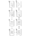
図1に、本発明に従ったウエブ印刷工程の8つのセクションを示す模式的な線図が示されている。セクション1は、巻出しユニット101である。セクション2は前処理ステーション102である。セクション3はカーボン印刷ステーション103である。セクション4は絶縁印刷ステーション104である。セクション5は第1の酵素印刷ステーション105である。セクション6は第2の酵素印刷ステーション106である。セクション7は巻取りユニット107である。セクション8はパンチ108である。次に示す記載はこれら8つのセクションの工程及び装置についてであるが、当業者であれば、本発明の工程及び装置を8つよりも多いまたは少ないセクションで具現できることを理解できよう。例えば、この実施形態には4つの印刷ステーションが含まれているが、本発明の範囲から逸脱することなく1または複数の印刷ステーションを用いることができる。一実施形態では、電極層及び試薬層を印刷するための印刷ステーションは最小の2つである。
FIG. 1 shows a schematic diagram showing eight sections of a web printing process according to the present invention. Section 1 is an unwinding
本発明の一実施形態では、セクション1は、イリノイ州ロックフォードに所在のマーチン・オートマチック社(Martin Automatic Inc.)が販売するマーチン・アンワインダー/オートマチック・スプライス(Martin Unwinder/Automatic Splice)などの基板材料巻出しユニット101で具現することができる。本発明のこの実施形態では、セクション2‐6は、ドイツのブンデ(Bunde)に所在のワーナー・カマン・マシンファブリック社(Werner Kammann Maschinefabrik Gmbh)が販売する修正カマン・プリンター(kammann Printer)(モデル番号4.61.35)で具現することができる。本発明のこの実施形態では、セクション2は前処理ユニット102とすることができる。前処理ユニット102で、印刷の前に基板242を前処理することができ、セクション3−6で、基板242にカーボンインキ、絶縁インキ、第1の酵素インキ、及び第2の酵素インキをスクリーン印刷することができる。セクション7は、イリノイ州ロックフォードに所在のマーチン・オートマチック社が販売するマーチン・リワインダー(Martin Rewinder)などの巻取りユニット107を備えることができる。セクション8は、カンザス州レネクサ(Lenexa)に所在のプレコプレス(Preco Press)が販売するプレコパンチ(Preco punch)(モデル番号2024‐P‐40T XYT CCD CE)などのパンチ108を備えることができる。装置の具体的なモデル番号について述べたが、当業者には明らかなように、本発明の範囲から逸脱することなくこのような装置を変更、置換、または排除することができる。
In one embodiment of the present invention, Section 1 is a substrate such as a Martin Unwinder / Automatic Splice sold by Martin Automatic Inc. of Rockford, Illinois. The
図2A‐図2Cに、本発明に従ったウエブ印刷方法のセクション1‐8を通過する基板242の経路を例示する模式的な線図が示されている。本発明の一実施形態では、基板242に用いる材料は、デュポン・テイジン・フィルムズ(Dupont Teijin Films)が製造するポリエステル材料(Melinex(登録商標)ST328)とすることができる。基板242は、例えば、厚み350μm、幅370mm、長さ約660mの公称寸法とすることができるロール材料で供給される。このような厚み及び幅の寸法は、フラットスクリーン印刷により基板のウエブに電気化学センサを製造するのに特に適していることが分かっている。これは、材料には印刷に耐える十分な強度と装置を通る柔軟性が必要であり、本方法を商業用に使用可能にするために適当な数量のセンサを受容できる十分な幅が必要であるためである。基板242には、インキの付着を改善するために片側または両側にアクリルコーティングを設けることができる。ポリエステルは、本発明に従ったウエブ工程における高い温度及び高い張力に十分に耐えるため好適な材料である。実際にはMelinex(登録商標)であるポリエステルが本発明の一実施形態に好適な材料であるが、当業者であれば、本開示から他の材料を使用できることも理解できよう。実際に、特に材料の厚み、幅、及び長さの変更が可能であり、幅または長さを大きくすれば、より多くのセンサを製造することができ、材料の厚みを変更すれば、場合によっては前処理や印刷中の見当合わせが容易になる。本発明の好適な実施形態では、カーボン印刷ステーション103に移送される前に、基板242に大きな張力をかけずに最大185℃に加熱して基板242に熱安定処理を施し、温度が140℃〜160℃、張力が最大165Nになるウエブ印刷工程において基板242の歪みが最小になるようにする。通常は、ウエブをヒーターに通すのに十分な最小の張力を使用する。しかしながら、この加熱安定処理にもかかわらず、印刷ステップから印刷ステップへの見当合わせでばらつきが起こり、これによりセンサに欠陥が生じることが分かった。従って、前処理ステップは印刷の直前に行われる。詳細を後述するように、前処理ステップ(セクション1)では、後続の印刷ステップの温度よりも高い温度(通常は160℃)まで基板を加熱する。好適な一実施形態では、この前処理ステップで、基板に、通常は約165Nである張力がかかる。実際にこの実施形態では、この前処理と張力をかけることにより、印刷見当合わせにおけるばらつきが大幅に軽減でき、得られる製品の収量を改善することができる。本発明の一実施形態では、基板242のロールは、例えば、インターテープ・ポリマー・グループ(Intertape Polymer Group)が販売するPS-1スプライシング・フラット・バック・ペーパー・テープ(PS-1 Splicing Flat-back Paper Tape)などの接合テープを用いて巻出しユニット101または巻取りユニット107で互いに接合される。
2A-2C are schematic diagrams illustrating the path of the
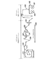
図2Aに、本発明の一実施形態に従ったウエブ印刷工程のセクション1及びセクション2を示す模式的な線図が示されている。図2Aでは、セクション1は巻出しユニット101である。巻出しユニット101は、第1のアーバー200、第2のアーバー201、第1の接合ユニット202、及び第1のアキュムレータ203を含む。図2Aでは、セクション2は前処理ステーション102である。前処理ステーション102は、第1の清浄ユニット204、通常は使用されない第2の接合ユニット205、インバウンドニップローラ206、第2の清浄ユニット207、ロードセル208、第1の印刷ローラ209、第1の駆動ローラ210、及び第1の乾燥ゾーン211を含む。
FIG. 2A shows a schematic diagram illustrating sections 1 and 2 of a web printing process according to one embodiment of the present invention. In FIG. 2A, section 1 is the unwinding
図2Aに例示されている本発明の実施形態では、巻出しユニット101は、例えば、約80Nの張力で基板242を前処理ステーション102内に連続的に移送するを促進するマーチン・アンワインダー/オートマチック・スプライス(Martin Unwinder/Automatic Splice)からなる。巻出しユニット101は、第1の巻出しアーバー200及び第2の巻出しアーバー201を含むことができる。アーバーはマンドレルとも呼ぶことに留意されたい。第1の巻出しアーバー200は、基板材料242のロールを保持し、基板242をセクション2の前処理ステーション102内に連続的に供給する。第2の巻出しアーバー201は、基板242の予備のロールを保持し、この予備のロールは第1の巻出しアーバー200からの基板242のロールの端部に自動的に接合され、基板242が半連続的に供給される。この連続的な工程が、第1の巻出しアーバー200から第2の巻出しアーバー201に繰り返される。基板材料アキュムレータ203が、所定長さの基板242を蓄え、その蓄えた基板242をセクション2の前処理ステーション102内に供給し、その一方で第1の接合ユニット202で接合が行われる(この時、第1の巻出しアーバー200と第2の巻出しアーバー201は静止している)。形成された接合部は、その接合部において材料の一側に所定長さの接合テープを含む突合せ接合である。品質を確保するために、接合部の一側の約10mの印刷された基板を廃棄することができる。第1の巻出しアーバー200及び第2の巻出しアーバー201は、基板242を第1の接合ユニット202内に案内するウエブ端部ガイド(不図示)を含む。このウエブ端部ガイドは、第1の接合ユニット202に供給される時に基板242が離脱するのを防止するように適合されている。
In the embodiment of the invention illustrated in FIG. 2A, the unwinding
一般に、本発明の装置は、一度に2個〜10個、通常は6個の基板のロールを製造するように設定される。これらの印刷ステーションがインキの連続的な供給源に接続されている場合、通常は使用するロールの数は問題ではない。しかしながら、制限された量のインキが供給される2つの酵素印刷ステーションの場合は、使用するロールの数は重要な入力パラメータである。実際に、使用するロールの数量により、印刷工程が始まる前にスクリーンに供給するインキの量が決定される。例えば6個のロールを用いる場合、6個またはそれ以上のロールに相当する酵素インキを、セクション5及びセクション6のそれぞれで印刷を開始する前にスクリーン上に供給する。従って、酵素インキは、印刷運転の全体に亘って持続的に酵素を印刷できるように、印刷運転の間、印刷のために用意しておく必要がある。酵素印刷ステーションのスクリーンに壁部が設けられており、これにより、印刷中にスクリーンに補給しなくても済む十分な量の酵素インキをスクリーンに導入することができ、酵素インキがスクリーンをオーバーフローしてその下側を通るウエブ基板に流れることがない。 In general, the apparatus of the present invention is set up to produce a roll of 2 to 10 substrates, usually 6 substrates at a time. When these printing stations are connected to a continuous source of ink, the number of rolls normally used does not matter. However, in the case of two enzyme printing stations where a limited amount of ink is supplied, the number of rolls used is an important input parameter. In practice, the number of rolls used determines the amount of ink that is fed to the screen before the printing process begins. For example, if 6 rolls are used, enzyme inks corresponding to 6 or more rolls are fed onto the screen before printing begins in sections 5 and 6 respectively. Accordingly, the enzyme ink needs to be prepared for printing during the printing operation so that the enzyme can be continuously printed throughout the printing operation. The screen of the enzyme printing station is provided with a wall so that a sufficient amount of enzyme ink can be introduced into the screen without having to replenish the screen during printing, and the enzyme ink overflows the screen. It does not flow to the web substrate passing under the lever.
本発明の一実施形態では、基板242は、印刷する4つの層の見当合わせを維持するために(通常は、印刷見当合わせの許容差は300μm)、工程中は約165Nの張力で保持される。基板242はまた、それぞれの印刷ステップで印刷されたインキを乾燥させるために140℃またはそれ以下の様々な温度にさらされる。この張力と温度により、基板242が工程中に伸長または膨張して、見当合わせの許容差から外れる場合がある。実際に、印刷ステージから印刷ステージ、印刷運転から印刷運転、及び印刷運転中における実際のイメージサイズの変動は、予測不可能であり、許容差よりも大きくなり得る。
In one embodiment of the present invention, the
図2Aに例示されている本発明の実施形態では、セクション2は前処理ステーション102である。前処理は、イメージが基板に印刷される前に行われる。基板242は、ウエブ工程の後続のセクションでの膨張及び伸長を小さくするために、及びセクション3‐6における基板242の見当合わせを助けるために前処理される。前処理ステーションでは、後続の印刷ステップにおける温度を超えない温度まで基板242を加熱することができる。この前処理は、通常は150N〜180N、より一般的には約165Nの張力で行われる。しかしながら、別の実施形態では、前処理ステーション102で、場合によっては上記したような張力を加えて、基板242から不可逆的な伸長を取り除くために十分な温度まで基板242を加熱することができる。
In the embodiment of the invention illustrated in FIG. 2A, section 2 is a
本発明の一実施形態では、基板は、図11に詳細に例示されている前処理ゾーン211で約160℃まで加熱される。上記したように、本発明の一実施形態では、前処理ステーション102で基板242が加熱される温度は、後続の乾燥ステップを含む基板242の後続の工程の温度未満である。後続の印刷工程は、前処理ステーション102の処理で生じる伸長によるわずかに拡大したイメージを、やや大きいステンシルスクリーン(ウエブの移動方向に通常は750μm)を用意して補正することができる。新しいスクリーンの用意は問題となり得る。従って、スクリーンを交換しないでイメージの大きさの変動に対応するために、スクリーンとウエブの相対速度などの他のパラメータをそれぞれの印刷ステーションで変更することができる。しかしながら、対応できるイメージの大きさの変動は限られている。従って、ここで記載するように基板を前処理して全体のイメージの大きさの増大を軽減し、そのイメージの大きさの増大のばらつきを小さくするのが好ましい。
In one embodiment of the invention, the substrate is heated to about 160 ° C. in the
本発明の一実施形態では、前処理ステーション102は、本発明に従ったウエブ製造工程の適切な動作を促進する機能を果たす別の要素を含む。前処理ユニット102には、基板242の上面及び下面を清浄する第1の清浄ユニット204及び第2の清浄ユニット207の2つのウエブ清浄ユニットが設けられている。第1の清浄ユニット204及び第2の清浄ユニット207は、印刷ステップの前に基板242から微粒子を除去するために粘着剤がコーティングされたローラを用いる。第1の清浄ユニット204は、例えば、英国のグラスゴーに所在のKSMウエブ・クリーナーズ(KSM Web Cleaners)が販売するクリーナー(モデル番号WASP400)とすることができる。第2の清浄ユニット207は、例えば、テクネック(Teknek)が販売するクリーナーとすることができる。前処理ステーション102は更に、インバウンドニップローラ206及びロードセル208を含む。インバウンドニップローラ206は、基板242の張力(特に、インバウンドニップローラ206とアウトバウンドニップローラ238との間の張力)を制御するために用いられる。インバウンドニップローラ206は、制御システム(不図示)を介してロードセル208に連結されている。基板242は、アウトバウンドニップローラ238によって一定速度でセクション6の第2の酵素印刷ステーション106から取り除かれる。セクション2のロードセル208は、本発明に従って基板242がウエブ工程を通過する時に基板242の張力を測定する。インバウンドニップローラ206は、所定の設定点でその張力を制御するためにその速度を調節する。本発明に従ったウエブ製造工程における通常の基板の張力は、約150N〜180Nであり、より具体的には160N〜170Nであり、この実施形態では約165Nである。
In one embodiment of the invention, the
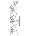
図2Bに、本発明に従ったウエブ印刷工程のセクション3‐5を示す模式的な線図が示されている。図2Bでは、セクション3はカーボン印刷ステーション103である。印刷の前に、上部ブラシ/吸引ステーション251と底部ブラシ/吸引ステーション250が互いにオフセットされた吸引/ブラシシステムを用いて基板の上面(印刷面)及び下面を清浄する清浄システム(ミーチ(Meech)が販売)が設置される。上部ブラシ/吸引ステーション251は、カーボン印刷の前にアクセス可能な最も近い点であり、冷却ローラ212及びアキュムレータ213の直前で基板に接触する。底部ブラシ/吸引ステーション251は、基板が前処理ユニット102を出た直後に基板に接触する。カーボン印刷ステーション103は、第1の冷却ローラ212、第2のアキュムレータ213、第2の印刷ローラ214、第1の視覚センサ215、第2の駆動ローラ216、第1の乾燥ゾーン217、及び第2の冷却ローラ218を含む。図2Bに例示されている本発明の実施形態では、セクション4は絶縁印刷ステーション104である。絶縁印刷ステーション104は、第3の冷却ローラ219、第3のアキュムレータ220、第3の印刷ローラ221、第2の視覚センサ222、位置237Aにおける第1のY方向見当合わせシステム(不図示)、第3の駆動ローラ223、及び第2の乾燥ゾーン224を含む。図2Bにおいて、セクション5は第1の酵素印刷ステーション105である。第1の酵素印刷ステーション105は、第4の冷却ローラ225、第4のアキュムレータ226、第4の印刷ローラ227、第3の視覚センサ228、位置237Bにおける第2のY方向見当合わせシステム(不図示)、第4の駆動ローラ229、及び第3の乾燥ゾーン230を含む。
FIG. 2B shows a schematic diagram illustrating sections 3-5 of the web printing process according to the present invention. In FIG. 2B, section 3 is a
本発明に従った工程では、ウエブ製造工程のセクション3でカーボン印刷が行われる。もちろん、当業者には明らかなように、広い意味で本発明から逸脱することなく印刷工程の数及び種類は様々に変更することができる。例えば、2つのカーボン印刷を形成する、或いは金属粒子を含むカーボンインキ、銀/塩化銀インキ、または金やパラジウムを用いたインキの1または複数の印刷を用いて電極層を電気化学センサに設けることができる。絶縁層及び試薬層もまた、組成、堆積の順序、堆積の厚み、レイアウト、並びにここに記載した実施形態から当業者に明らかな他のパラメータを様々に変更することができる。セクション3では、本発明に従って製造される電気化学センサのカーボンアートワークをスクリーン印刷で印刷することができる。カーボン印刷ステーション103の基本的な構成要素が図6及び図7に例示されている。具体的には、本発明に従った好適な印刷ステーションは、スクリーン301、下部印刷ローラ303、印刷ローラ600、フラッドブレード603、スキージホルダー605、及びスキージ606を含む。カーボン印刷ステーション103では、印刷ローラ600は第2の印刷ローラ214である。スクリーン301は、概ね平坦な構造であって、通常は所望のアートワークのネガティブを提供するように配置されたメッシュを含む。カーボンインキがメッシュに供給され、印刷中にそのメッシュから押し出される。この段階で、平坦なスクリーンが、インキの重量によって平坦な形状からやや変形し(これは、通常は印刷運転全体で使用されるインキの全てが印刷運転の開始時にスクリーンに堆積される酵素印刷ステップで特に顕著である)、スキージからの圧力によりインキがメッシュのステンシルから押し出される。
In the process according to the invention, carbon printing is performed in section 3 of the web manufacturing process. Of course, it will be apparent to those skilled in the art that the number and type of printing steps can be varied in various ways without departing from the invention in a broad sense. For example, forming an electrode layer on an electrochemical sensor using two carbon prints or using one or more prints of carbon ink containing metal particles, silver / silver chloride ink, or ink using gold or palladium. Can do. The insulating and reagent layers can also vary in composition, deposition order, deposition thickness, layout, and other parameters apparent to those skilled in the art from the embodiments described herein. In Section 3, the carbon artwork of the electrochemical sensor produced according to the present invention can be printed by screen printing. The basic components of the
本発明に従ったフラッドサイクル工程では、スキージ606、フラッドブレード603、印刷ローラ600、及び下部印刷ローラ303が基板242のウエブの移動に一致する第1の方向608に移動してスクリーン301にインキ604が導入される。インキ604がスクリーン301に導入されるフラッドサイクルのために、スクリーン301が基板242の第1の方向608とは反対側の第2の方向607に移動する。
In the flood cycle process according to the present invention, the
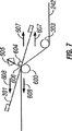
本発明に従った後続の印刷サイクル工程では、図7に例示されているように、スキージ606により、インキ604がスクリーン301を介して基板242に移送される。この印刷サイクルの際に、スキージ606、フラッドブレード603、印刷ローラ600、及び下部印刷ローラ303の全てが、基板242のウエブの移動とは反対の第2の方向607に移動する。スクリーン301が、インキ604がスクリーン301から押し出されて基板242に堆積される印刷サイクルのために、基板242のウエブの移動に一致する第1の方向608に移動する。従って、この印刷サイクルの際に、スクリーン301が、基板と同じまたはほぼ同じ速度でウエブ基板と同じ方向に移動する。スクリーン301は、静止している時は実質的に平坦であるが、使用時には、スキージ606によってウエブに対して押圧されるためやや撓み、スキージ606が取り除かれると元の形状に実質的に戻る。次いで、スクリーン301が、次の印刷サイクルの準備としてインキ604が導入される時に基板と反対方向に移動する。インキがスクリーン301に導入されると、インキの重量によりスクリーンがやや撓み得る。スクリーン301が印刷ステーションを離れる時に、ウエブの移動方向608に対して所定の角度を成している。この構成により(この角度は、通常は約10度〜30度であり、より具体的には約15度である)、スクリーンから基板へのインキの供給が改善され、印刷の鮮明度及び再現性が改善される。基板に対する印刷の角度、スキージ角度、スキージに対するスクリーンの距離、印刷ローラに対するスキージの位置、スナップ距離、基板とスクリーンの相対速度、及びスキージの圧力を全て用いて、カード全体の得られる印刷の鮮明度及び一貫性を制御し最適にすることができる(スクリーン印刷機構の一実施形態が、言及することを以って本明細書の一部とする米国特許第4,245,554号に詳細に開示されている)。
In a subsequent printing cycle process according to the present invention, the
具体的には、カーボン印刷ステーション103では、用いられるインキはカーボンインキである。好適なカーボンインキの例を以下に示す。本発明のこの実施形態では、スクリーン301にインキ604が導入されてから、スキージ606によりインキ604がスクリーンを介して基板242上に移送される。次いで、基板242に堆積された印刷カーボンネットワークに、例えば、図12に詳細に例示されている第1の乾燥ゾーン217内の4つの別々の乾燥バンクを用いて基板の印刷面に140℃の熱風が当てられ乾燥させられる。
Specifically, in the
カーボン印刷ステーションに用いるのに適したインキは、限定するものではないが、金属粒子を含むカーボン導電性印刷インキ、銀/塩化銀の導電性印刷インキ、金を用いた導電性印刷インキ、パラジウムを用いた導電性印刷インキを挙げることができる。 Suitable inks for use in carbon printing stations include, but are not limited to, carbon conductive printing inks containing metal particles, silver / silver chloride conductive printing inks, conductive printing inks using gold, palladium. The conductive printing ink used can be mentioned.
導電インキの他の種類、例えば、金属粒子を含むカーボン導電性印刷インキ、銀/塩化銀の導電性印刷インキ、金を用いた導電性印刷インキ、パラジウムを用いた導電性印刷インキを用いることができる。 Other types of conductive ink, such as carbon conductive printing ink containing metal particles, silver / silver chloride conductive printing ink, conductive printing ink using gold, conductive printing ink using palladium it can.
本発明の一実施形態では、カーボン印刷工程の前の乾燥の直後に、基板242が、通常は室温(約18℃〜21℃で、通常は19.5℃±0.5℃)である所定の温度まで急速に基板242を冷却するようにデザインされた第1の冷却ローラ212上を通過する。本発明に従ったウエブ製造工程の一実施形態では、第1の冷却ローラ212の表面は約18℃である。第1の冷却ローラ212は、例えば、約7℃の工場冷却水を用いて適切な温度まで冷却することができる。ローラの温度は、工場冷却水の流速及び/または温度を制御して制御することができる。印刷工程で、印刷カーボンパターンが堆積されたら、基板242が第2の冷却ローラ218を通過する。基板242の温度を下げて維持することは、低い温度によって、印刷の際にスクリーン上でインキが乾燥してメッシュにブロックが形成される可能性が小さくなるため有益である。本発明に従ったウエブ製造工程における冷却ローラの使用も、基板242の伸長を軽減するため有益であり、見当合わせの問題が軽減され、この問題を補正するために工程を迅速に改良する必要性が小さくなる。
In one embodiment of the present invention, immediately after drying prior to the carbon printing process, the
一実施形態では、冷却ローラの温度は、その冷却ローラの温度を測定して水の流れ/温度を制御するフィードバックループによって動的に制御される。ローラを冷却する他の方法、例えば電動冷凍ユニットなどが、当業者には上記した実施形態から明らかであろう。 In one embodiment, the temperature of the chill roller is dynamically controlled by a feedback loop that measures the temperature of the chill roller and controls the water flow / temperature. Other methods of cooling the roller, such as an electric refrigeration unit, will be apparent to those skilled in the art from the embodiments described above.
本発明に従った工程では、ウエブ製造工程のセクション4で、絶縁印刷が行われる。セクション4では、本発明に従って製造される電気化学センサのための絶縁アートワークが概ね平坦なスクリーンを用いるスクリーン印刷で印刷される。図6及び図7に、絶縁印刷ステーション104の基本的な構成要素が例示されている。具体的には、本発明に従った好適な印刷ステーションは、スクリーン301、下部印刷ローラ303、印刷ローラ600、フラッドブレード603、スキージホルダー605、及びスキージ606を含む。絶縁印刷ステーション104では、印刷ローラ600は第3の印刷ローラ221である。
In the process according to the invention, insulative printing is performed in section 4 of the web manufacturing process. In section 4, insulating artwork for an electrochemical sensor manufactured according to the present invention is printed with screen printing using a generally flat screen. 6 and 7 illustrate the basic components of the
本発明に従ったフラッドサイクル工程では、スキージ606、フラッドブレード603、印刷ローラ600、及び下部印刷ローラ303が基板242のウエブの移動に一致する第1の方向608に移動してスクリーン301にインキ604が導入される。インキ604がスクリーン301に導入されるフラッドサイクルのために、スクリーン301が基板242の第1の方向608とは反対の第2の方向607に移動する。
In the flood cycle process according to the present invention, the
本発明に従った後続の印刷サイクル工程では、図7に例示されているように、スキージ606により、インキ604がスクリーン301を介して基板242上に移送される。この印刷サイクルの際に、スキージ606、フラッドブレード603、印刷ローラ600、及び下部印刷ローラ303の全てが、基板242のウエブの移動とは反対の第2の方向607に移動する。スクリーン301が、インキ604がスクリーン301から押し出されて基板242に堆積される印刷サイクルのために、基板242のウエブの移動に一致する第1の方向608に移動する。スクリーン印刷機構の一実施形態が、言及することを以って本明細書の一部とする米国特許第4,245,554号に詳細に開示されている。
In a subsequent printing cycle process according to the present invention, the
可動フラットスクリーン印刷では、印刷の際に、概ね平坦なスクリーンが、基板とほぼ同じ速度で同じ方向に移動する成分を有する。それぞれの印刷ステーションでは、一般的に、実質的に平坦なスクリーンは、スクリーン及び基板が印刷位置(図6の印刷ローラ200の近傍)から離れる時に基板に対して鋭角(図6のA)をなす。基盤とスクリーン相対速度の変動により、基板の移動方向すなわちX方向における印刷イメージの大きさが変化する。
In movable flat screen printing, during printing, a generally flat screen has a component that moves in the same direction at approximately the same speed as the substrate. In each printing station, the substantially flat screen generally makes an acute angle (A in FIG. 6) to the substrate as the screen and substrate move away from the printing position (near the
それぞれの印刷ステーションに用いられるステンシルスクリーンは通常、延ばされて硬いフレームに取り付けられた弾性的に変形可能なポリエステルまたは金属メッシュからなる。一実施形態では、英国ウェイマスに所在のDEKマシーナリー(DEK Machinery)が販売するポリエステルスクリーンが用いられる。このメッシュは、フィルムポジティブと共にUV感受性コーティングでコーティングされ、このスクリーンが、UV光源で照射され、現像され、乾燥され、スクリーン上の乾燥したコーティングが所望のアートワークイメージのネガティブを形成する。スキージの助けで、インキがステンシルの開口領域を通過して基板に堆積される(インキによって形成されたポジティブイメージが基板上に形成される)。このフレームが、メッシュを取り付ける手段となり、伸長したメッシュによる力に対して最小の歪みで耐え、印刷の際に生じる更なる力に耐える。 The stencil screen used in each printing station is usually composed of an elastically deformable polyester or metal mesh that is stretched and attached to a rigid frame. In one embodiment, a polyester screen sold by DEK Machinery, located in Weymouth, UK, is used. The mesh is coated with a film positive with a UV sensitive coating, the screen is irradiated with a UV light source, developed and dried, and the dried coating on the screen forms the negative of the desired artwork image. With the aid of a squeegee, ink passes through the open area of the stencil and is deposited on the substrate (a positive image formed by the ink is formed on the substrate). This frame provides a means for attaching the mesh, withstands the forces caused by the stretched mesh with minimal distortion and withstands additional forces generated during printing.
具体的には、絶縁印刷ステーション104では、用いられるインキは絶縁インキである。好適な絶縁インキの例を以下に示す。本発明のこの実施形態では、スクリーン301にインキ604が導入されてから、スキージ606によりインキ604がスクリーンを介して基板242上に移送される。次いで、基板242に堆積された印刷絶縁アートワークに、例えば、図13に詳細に提示されている第2の乾燥ゾーン224内の4つの別々の乾燥バンクを用いて基板の印刷面に140℃の熱風が当てられ乾燥させられる。本発明に従ったウエブ製造工程の絶縁印刷ステーションに用いるのに適したインキの例として、エクロン社(Ercon, Inc)から購入することができるエクロンE6110−116ジェット・ブラック・インスレイヤー・インキ(Ercon E6110-116 Jet Black Insulayer Ink)を挙げることができる。本発明の一実施形態では、絶縁ネットワークが、ここに記載する技術を用いて装置に沿ったX方向及び装置を横断するY方向にカーボンアートワークに対して見当合わせされる。当業者であれば、本開示から、他の種類の絶縁インキを利用できることを理解できよう。更に、様々な層または様々な順序の層を用いて、様々な順序の層を形成し、これにより電気化学センサに異なった構造を形成することができる。
Specifically, in the insulating
本発明の一実施形態では、絶縁印刷工程の前の乾燥の直後に、印刷カーボン及び絶縁パターンを含む基板242が、通常は室温(約17℃〜21℃で、通常は19.5℃±0.5℃)である所定の温度まで急速に基板242を冷却するようにデザインされた第3の冷却ローラ219上を通過する。本発明に従ったウエブ製造工程の一実施形態では、第3の冷却ローラの表面温度は約18℃である。第3の冷却ローラ219は、例えば、約7℃の工場冷却水を用いて適切な温度まで冷却することができる。基板242の温度を下げて維持することは、低い温度によって、スクリーン上でインキが乾燥してメッシュにブロックが形成される可能性が小さくなるため有益である。本発明に従ったウエブ製造工程における冷却ローラの使用も、基板242の伸長を軽減するため有益であり、見当合わせの問題が軽減され、この問題を補正するために工程を迅速に改良する必要性が小さくなる。
In one embodiment of the invention, immediately after drying prior to the insulating printing process, the
本発明に従った工程では、ウエブ製造工程のセクション5で、第1の酵素印刷が行われる。セクション5では、本発明に従って製造される電気化学センサのための酵素インキのアートワークが、上記した概ね平坦な可動スクリーン及びスクリーン印刷を用いて印刷される。第1の酵素印刷ステーション105の基本的な構成要素が図6及び図7に例示されている。具体的には、本発明に従った好適な印刷ステーションは、スクリーン301、下部印刷ローラ303、印刷ローラ600、フラッドブレード603、スキージホルダー605、及びスキージ606を含む。第1の酵素印刷ステーション105では、印刷ローラ600は第4の印刷ローラ227である。
In the process according to the invention, the first enzyme printing is performed in section 5 of the web manufacturing process. In section 5, enzyme ink artwork for an electrochemical sensor manufactured according to the present invention is printed using the generally flat movable screen and screen printing described above. The basic components of the first
本発明に従ったフラッドサイクル工程では、スキージ606、フラッドブレード603、印刷ローラ600、及び下部印刷ローラ303が基板242のウエブの移動に一致する第1の方向608に移動してスクリーン301にインキ604が導入される。インキ604がスクリーン301に導入されるフラッドサイクルのために、スクリーン301が基板242の第1の方向608とは反対の第2の方向607に移動する。
In the flood cycle process according to the present invention, the
本発明に従った後続の印刷サイクル工程では、図7に例示されているように、スキージ606により、インキ604がスクリーン301を介して基板242上に移送される。この印刷サイクルの際に、スキージ606、フラッドブレード603、印刷ローラ600、及び下部印刷ローラ303の全てが、基板242のウエブの移動とは反対の第2の方向607に移動する。スクリーン301が、インキ604がスクリーン301から押し出されて基板242上に堆積される印刷サイクルのために、基板242のウエブの移動に一致する第1の方向608に移動する。スクリーン印刷の機構の一実施形態が、言及することを以って本明細書の一部とする米国特許第4,245,554号に詳細に開示されている。
In a subsequent printing cycle process according to the present invention, the
具体的には、第1の酵素印刷ステーション105では、用いられるインキは酵素インキである。好適な酵素インキの例を以下に示す。本発明のこの実施形態では、スクリーン301にインキ604が導入されてから、スキージ606によりインキ604がスクリーンを介して基板242上に移送される。次いで、基板242に堆積された印刷酵素アートワークに、例えば、図14に詳細に例示されている第3の乾燥ゾーン230内の2つの別々の乾燥バンクを用いて基板の印刷面に50℃の熱風が当てられ乾燥される。本発明に従ったウエブ製造工程の第1の酵素印刷ステーション105に用いるのに適したインキの例が表1に示されている。

本発明の一実施形態では、絶縁印刷工程の後の乾燥の直後に、印刷カーボン及び絶縁パターンを含む基板242が、通常は室温(約17℃〜21℃で、通常は19.5℃±0.5℃)である所定の温度まで急速に基板242を冷却するようにデザインされた第4の冷却ローラ225上を通過する。本発明に従ったウエブ製造工程の一実施形態では、第4の冷却ローラ225の表面は約18℃である。第4の冷却ローラ225は、例えば、約7℃の工場冷却水を用いて適切な温度まで冷却することができる。基板242の温度を下げて維持することは、低い温度によって、スクリーン上でインキが乾燥してメッシュにブロックが形成される可能性が小さくなるため有益である。本発明に従ったウエブ製造工程における冷却ローラの使用も、基板242の伸長を軽減するため有益であり、見当合わせの問題が軽減され、この問題を補正するために工程を迅速に改良する必要性が小さくなる。
In one embodiment of the invention, immediately after drying after the insulating printing process, the
加えて、スクリーンの移動による空気の流れ及び酵素インキの高い含水率のせいで、酵素インキがスクリーンで乾燥しないようにすることが極めて重要である。スクリーンの移動による空気の相対的な流れによりスクリーン上のインキが乾燥するが、この現象は、本発明とは異なる装置内でスクリーンが移動しないフラッドベッドスクリーンプリンター(Thiemeフラッドベッドプリンターなど)では通常は観察されない。酵素スクリーン印刷ステップの前に、冷却ローラにより基板が約18℃に冷却されて乾燥が緩和されるのに加え、酵素インキが導入されたスクリーンが印刷中に加湿される。一実施形態では、加湿は実質的に連続的である。スクリーンの上面、底面、及び/または側面を加湿することができ、実際にはこれら全ての面を加湿することができる。配管により、スクリーンの上方、下方、及び側方に実質的に一定な湿り空気の流れを供給して、インキの含水率を一定レベルに維持することができる。本発明に従ったスクリーンの上面、底面、及び/または側面を加湿するための好適な構成が図3-図5に例示されている。加湿手段(通常は加湿空気を移送するパイプ)の量及び構成は、とりわけ、必要な加湿量、インキの含水率、周囲空気の湿度及び温度、基板が酵素印刷ステーションに近づく時の基板の温度、印刷ローラの温度、スクリーンの大きさ、並びに周囲(加湿されていない空気)に対するスクリーンの露出などによって異なる。一実施形態では、1または複数列の孔400を含むパイプ304が、スクリーンが前後する1ストローク中にスクリーンの底面全体に湿り空気を供給する。装置の上側及び装置の操作側のパイプ(不図示)が湿り気流300及び302(図4を参照)を供給する。
In addition, it is very important that the enzyme ink does not dry on the screen due to the air flow due to the movement of the screen and the high moisture content of the enzyme ink. Although the ink on the screen dries due to the relative flow of air due to the movement of the screen, this phenomenon is usually observed in a flood bed screen printer (such as a Thiem flood bed printer) in which the screen does not move in an apparatus different from the present invention. Not observed. Prior to the enzyme screen printing step, the substrate is cooled to about 18 ° C. by a cooling roller to alleviate drying and the screen with the enzyme ink introduced is humidified during printing. In one embodiment, the humidification is substantially continuous. The top, bottom, and / or sides of the screen can be humidified, and in fact all these surfaces can be humidified. The piping allows a substantially constant flow of moist air to be supplied above, below, and to the sides of the screen to maintain the ink moisture content at a constant level. A suitable configuration for humidifying the top, bottom and / or sides of a screen according to the present invention is illustrated in FIGS. 3-5. The amount and configuration of the humidifying means (usually pipes that transport humidified air) include, among other things, the amount of humidification required, the moisture content of the ink, the humidity and temperature of the ambient air, the temperature of the substrate as it approaches the enzyme printing station, It depends on the temperature of the printing roller, the size of the screen, and the exposure of the screen to the surroundings (unhumidified air). In one embodiment, a
通常は全印刷運転に必要な酵素インキが、印刷運転が始まる時またはその前にスクリーン上に配置される。酵素インキが含水率が高いため(通常は55wt%〜65wt%、より一般的には約60wt%)、酵素インキが印刷運転中に乾燥する傾向にある。このリスクは、酵素インキが入ったスクリーンの周りを加湿することで軽減することができる。別法または通常はこれに加えて、ここに開示するように冷却ローラを用いて、酵素(または任意の物質)印刷ステーションに入る前に基板を冷却することができる。一般に、基板の温度は、室温またはそれ以下に制御される。しかしながら、基板の温度は、室内の大気の露点よりも高く維持される。室内の湿度が60%の場合、露点は15℃である。基板の温度がこれよりも低下すると、基板上に結露が起こり、後続の印刷工程、特に酵素インキなどの水溶性インキを用いる後続の印刷工程が損なわれる可能性がある。基板の温度を、例えば室温と露点との間に制御することが印刷工程にとって重要である。温度及び/または冷却ローラ212、219、225、及び231の通過時間の管理が基板の温度の制御に重要である。フィードバック制御ループを用いて、例えば室温及び/または露点(部屋の湿度に依存)に対して基板の温度を測定し、基板が冷却ローラを離れて次の印刷ステーションに近づく時の基板の温度及び冷却ローラの温度を制御する。
Normally, the enzyme ink required for the entire printing operation is placed on the screen when or before the printing operation begins. Because the enzyme ink has a high water content (usually 55 wt% to 65 wt%, more generally about 60 wt%), the enzyme ink tends to dry during the printing operation. This risk can be mitigated by humidifying around the screen containing the enzyme ink. Alternatively, or in addition to this, the substrate can be cooled prior to entering the enzyme (or any material) printing station using a cooling roller as disclosed herein. In general, the temperature of the substrate is controlled at room temperature or lower. However, the temperature of the substrate is maintained higher than the dew point of the indoor atmosphere. When the indoor humidity is 60%, the dew point is 15 ° C. If the temperature of the substrate is lower than this, condensation may occur on the substrate, and the subsequent printing process, particularly the subsequent printing process using a water-soluble ink such as enzyme ink, may be impaired. It is important for the printing process to control the temperature of the substrate, for example, between room temperature and dew point. Management of the temperature and / or transit time of the cooling
図2Cに、本発明に従ったウエブ製造工程のセクション6及びセクション7を示す模式的な線図が示されている。図2Cでは、セクション6は第2の酵素印刷ステーション106である。第2の酵素印刷ステーション106は、第5の冷却ローラ231、第5のアキュムレータ232、第5の印刷ローラ233、第4の視覚センサ234、第5の駆動ローラ235、第5の乾燥ゾーン236、Y方向見当合わせシステム237、及びアウトバウンドニップローラ238を含む。図2Cに例示されている本発明の実施形態では、セクション7は巻取りユニット107である。巻取りユニット107は、ステアリング機構239、第1の巻取りアーバー240、及び第2の巻取りアーバー241を含む。
FIG. 2C shows a schematic diagram illustrating sections 6 and 7 of the web manufacturing process according to the present invention. In FIG. 2C, section 6 is a second enzyme printing station 106. The second enzyme printing station 106 includes a
本発明に従った工程では、ウエブ製造工程のセクション6で第2の酵素印刷が行われる。セクション6では、本発明に従って製造される電気化学センサのための酵素インキのアートワークがスクリーン印刷で印刷される。酵素インキを2回コーティングするのは、炭素電極を完全に覆い、炭素電極を実質的に均一にして空隙がないようにするためである。第2の酵素印刷ステーション106の基本的な構成要素が図6及び図7に例示されている。具体的には、本発明に従った好適な印刷ステーションは、スクリーン301、下部印刷ローラ303、印刷ローラ600、フラッドブレード603、スキージホルダー605、及びスキージ606を含む。第2の酵素印刷ステーション106では、印刷ローラ600は第5の印刷ローラ233である。
In the process according to the invention, a second enzyme printing is performed in section 6 of the web manufacturing process. In section 6, the enzyme ink artwork for an electrochemical sensor manufactured according to the present invention is printed by screen printing. The reason why the enzyme ink is coated twice is to completely cover the carbon electrode so that the carbon electrode is substantially uniform and free of voids. The basic components of the second enzyme printing station 106 are illustrated in FIGS. Specifically, a preferred printing station according to the present invention includes a
本発明に従ったフラッドサイクル工程では、スキージ606、フラッドブレード603、印刷ローラ600、及び下部印刷ローラ303を基板242のウエブの移動に一致する第1の方向608に移動してスクリーン301にインキ604が導入される。インキ604がスクリーン301に導入されるフラッドサイクルのために、スクリーン301が基板242の第1の方向608とは反対の第2の方向607に移動する。
In the flood cycle process according to the present invention, the
本発明に従った後続の印刷サイクル工程では、図7に例示されているように、スキージ606により、インキ604がスクリーン301を介して基板242上に移送される。この印刷サイクルの際に、スキージ606、フラッドブレード603、印刷ローラ600、及び下部印刷ローラ303の全てが、基板242のウエブの移動と反対の第2の方向607に移動する。スクリーン301が、インキ604がスクリーン301から押し出されて基板242上に堆積される印刷サイクルのために、基板242のウエブの移動に一致する第1の方向608に移動する。スクリーン印刷機構の一実施形態が、言及することを以って本明細書の一部とする米国特許第4,245,554号に詳細に開示されている。
In a subsequent printing cycle process according to the present invention, the
具体的には、第2の酵素印刷ステーション106では、用いられるインキは酵素インキである。本発明のこの実施形態では、スクリーン301にインキ604が導入されてから、スキージ606によりインキ604がスクリーンを介して基板242上に移送される。次いで、基板242に堆積された印刷酵素アートワークに、例えば、図15に詳細に例示されている第4の乾燥ゾーン236内の2つの別々の乾燥バンクを用いて基板の印刷面に50℃の熱風が当てられ乾燥される。第2の酵素印刷ステーション106に用いるのに適したインキの例は、表1に記載した第1の酵素印刷ステーションで使用される酵素インキと同じである。
Specifically, in the second enzyme printing station 106, the ink used is enzyme ink. In this embodiment of the present invention, after the
本発明の一実施形態では、第2の酵素印刷工程の後の乾燥の直後に、印刷カーボン、絶縁インキ、及び酵素インキのパターンを含む基板242が、所定温度まで急速に基板242を冷却するようにデザインされた第5の冷却ローラ231上を通過させる。本発明に従ったウエブ製造工程の一実施形態では、第5の冷却ローラ231の表面は約18℃である。第5の冷却ローラ231は、例えば、約7℃の工場冷却水を用いて適切な温度まで冷却することができる。基板242の温度を下げて維持することは、低い温度によって、スクリーン上でインキが乾燥してメッシュにブロックが形成される可能性が小さくなるため有益である。本発明に従ったウエブ製造工程における冷却ローラの使用も、基板242の伸長を軽減するため有益であり、見当合わせの問題が軽減され、この問題を補正するために工程を迅速に改良する必要性が小さくなる。
In one embodiment of the present invention, immediately after drying after the second enzyme printing step, the
加えて、スクリーンの移動による空気の流れ及び酵素インキの高い含水率のせいで、酵素インキがスクリーンで乾燥しないようにすることが極めて重要である。酵素スクリーン印刷ステップの前に、冷却ローラにより基板が18℃に冷却されて乾燥が緩和されるのに加え、スクリーンの上方及び下方に湿り空気の流れを供給してスクリーンの上面及び/または下面及び/または側面を加湿することにより、インキの含水率を一定レベルに維持することができる。通常は、湿り空気がスクリーン上を常に流れる。本発明に従ってスクリーンの上面及び下面を加湿するための好適な構造が図3に例示されている。 In addition, it is very important that the enzyme ink does not dry on the screen due to the air flow due to the movement of the screen and the high moisture content of the enzyme ink. Prior to the enzyme screen printing step, the substrate is cooled to 18 ° C. by a cooling roller to alleviate drying, and a stream of moist air is supplied above and below the screen to provide an upper and / or lower surface of the screen and By humidifying the side surfaces, the water content of the ink can be maintained at a certain level. Normally, moist air always flows over the screen. A suitable structure for humidifying the upper and lower surfaces of the screen in accordance with the present invention is illustrated in FIG.
第2の酵素印刷ステーション106は、アウトバウンドニップローラ238、見当合わせを確認するための検査システム237、237Cにおける第3のY方向見当合わせシステム(不図示)、及びバーコードステーション(不図示)を含む。アウトバウンドニップローラ238は、基板242の張力(具体的には、インバウンドニップローラ206とアウトバウンドニップローラ238との間の張力)の制御に用いられる。基板242が、アウトバウンドニップローラ238によって一定速度で第2の酵素印刷ステーション106から取り出される。位置237A、237B、及び237CにおけるY方向見当合わせシステム(不図示)が、図21Aに例示されている第1のY方向見当合わせマーク2101、第2のY方向見当合わせマーク2102、第3のY方向見当合わせマーク2103、及び第4のY方向見当合わせマーク2104を用いて印刷中にそれぞれの印刷サイクルのY方向見当合わせ(すなわち、ウエブを横断する方向)を制御する。本発明の一実施形態では、第1のY方向見当合わせマーク2101、第2のY方向見当合わせマーク2102、第3のY方向見当合わせマーク2103、及び第4のY方向見当合わせマーク2104はそれぞれ、カーボン印刷ステーション103、絶縁印刷ステーション104、第1の酵素印刷ステーション105、及び第2の酵素印刷ステーション106のY方向見当合わせに一致し得る。それぞれのY方向見当合わせマークは、矩形に近づく向きに近接した2つの三角形を含む。一実施形態では、位置237A、237B、及び237CにあるY方向見当合わせシステムに、ドイツのレオポルドショー(Leopoldshohe)に所在のエルトロマット社(Eltromat Gmbh)が販売するエルトロマットDGC650(Eltromat DGC650)を用いることができる。
The second enzyme printing station 106 includes an
本発明の一実施形態では、検査システム237に、ドイツのレオポルドショー(Leopoldshohe)に所在のエルトロマット社(Eltromat Gmbh)が販売するエルトロマット検査システム(Eltromat Inspection System)(モデル番号PC3100HD)を用いることができる。この検査システム237は、図17(A)‐図19(D)及び/または図20(D)に例示されている見当合わせマークを検査する視覚要素を有し、センサシート2106を不合格とするべきか否かについて評価する装置として用いることができる(例えば、データベースにバーコードに対する検査結果を記録する)。
In one embodiment of the present invention, the
Y方向における見当合わせの問題(237A、237B、及び237Cに位置する見当合わせシステム(不図示)によって印刷中に変更することができ、かつ/または全ての印刷ステップが終了した後で検査システム237で検査できる)は、ウエブの伸長におけるバラつきまたは基板242に対する不均一な歪みによって生じると考えられる。本発明の実施形態では、バーコードステーションは、コンポーネントバーコードプリンタ(英国ケンブリッジに所在のドミノUK社(Domino UK Ltd.)が販売(モデル番号A400))、バーコードトラバースシステム(スコットランドのパースシャイアー(Perthshire)に所在のスコティッシュ・ロボティック・システムズ(Scottish Robotic Systems))、及びバーコードリーダー(マサチューセッツ州カントン(Canton)に所在のRVSIアキュイティー・サイマトリックス(RVSI Acuity CiMatrix))を含む。バーコードステーション(不図示)では、2次元のバーコードがセンサシート2106の各列に貼り付けられる。これにより、それぞれのセンサの列に、固有の識別コード、バッチ/ロット番号の識別表示、センサのシート番号、及び列の番号が提供される。バーコードステーションはまた、印刷の直後にバーコードを読み取り、バーコードが適切に貼られていて装置の操作者が確認できるかを評価する。バーコード及びセクション2‐6の工程情報がデータベースに保存され、後にこれを用いて後の工程のためにカードを確認して不合格/合格を決定する。
Registration problems in the Y direction (which can be changed during printing by a registration system (not shown) located at 237A, 237B, and 237C and / or after all printing steps have been completed in the
巻取りユニット107は、例えばマーチン・オートマチック・リワインド・システム(Martin Automatic Rewind System)からなる。これは、装置の最後のセクションであり、基板242を連続的な巻取りを可能にする。巻取りユニット107は、第1の巻取りアーバー240及び第2の巻取りアーバー241からなる。第1の巻取りアーバー240は、基板材料242のロールを保持し、第2の酵素印刷ステーション106から材料を連続的に引張る。第2の巻取りアーバー241は、材料の予備のロールを保持しており、第1の巻取りアーバー24の基板242のロールが終了すると、第2のロールに第1のロールを自動的に接合する。この連続的な工程が、第1の巻取りアーバー240から第2の巻取りアーバー241に繰り返される。基板242が移動している時に迅速に接合されるため、基板242の連続的な巻取りが可能となる。この接合部は、両面粘着剤が用意された基板材料242の新しいロールの上に直接配置される。
The winding
図3に、ウエブ印刷のセクション5及び6の周りの湿度環境を示す模式的な線図が示されている。ウエブ印刷環境の加湿手段を提供するために用いられる基本的な構成要素が、図3に例示されているように、上部湿り空気300、スクリーン301、底部湿り空気302、下部印刷ローラ303、複数の孔400を含むパイプ304、基板242、及び第4の印刷ローラ227または第5の印刷ローラ233を含む。加湿及び温度は、酵素インキの性質が、フラッドサイクル及び印刷サイクル、好ましくは印刷の全工程に亘って著しく変質しないように設定する。具体的には、酵素インキの粘度及び含水率が、フラッドサイクル及び印刷サイクル、好ましくは印刷の全工程に亘って変質しないのが理想である。酵素インキの約63%が水分である。含水率を一定に保つことにより、基板242上に付着するインキの量が一定になる。印刷工程中にインキの含水率が変化すると、酵素層の厚みにばらつきがでる。加えて、酵素インキから水分が蒸発すると、スクリーン301上で酵素インキが乾燥して、印刷の鮮明度が低下し、基板242に付着するインキの量が少なくなる。第1の酵素印刷ステーション105または第2の酵素印刷ステーション106の内部の湿り空気は、85%〜95%の相対湿度に維持される。上部湿り空気300及び底部湿り空気302は、所望の相対湿度を維持するように、スクリーン301の両面に送られる。サイドパイプ305をウエブの一側に配置し、酵素印刷ステーション近傍のウエブの一側に加湿空気を導入する。加湿の構成の特性及び種類は、印刷ステーションの大きさ及び形状並びにその環境で印刷ステーションのインキの種類に必要な湿度によって異なり得る。しばしば、フードを用いて、スクリーンの上面及び/または下面を覆い、加湿空気がスクリーン近傍のフードに直接供給され、そのフードによってスクリーンの近傍に加湿空気が維持されるようにすることができる。通常はフードが上側のスクリーンフレームに取り付けられ、このような場合、通常のフラッドサイクル/印刷サイクルの際にスキージがスクリーンに対して移動できるようにフードがX方向(印刷の方向)のスロットを有することができる。
FIG. 3 shows a schematic diagram illustrating the humidity environment around sections 5 and 6 of the web print. The basic components used to provide the humidification means of the web printing environment are the top
図4に、ウエブ印刷のセクション5及び6の周りの湿度環境を示す底面図が示されている。ウエブ印刷環境の加湿手段を提供するために用いる基本的な構成要素は、図4に例示されているように、上部湿り空気300、スクリーン301、底部湿り空気302、孔の開いたパイプ304、孔400、及び305におけるサイドパイプ(不図示)を含む。複数の孔400を備えたパイプ304が、スクリーン301上の酵素インキの粘度を維持するために下部湿り空気302を送風するための手段としてスクリーン301の下側に配置されている。図5に、底部湿り空気302を送るために孔400を備えたパイプ304の斜視図が示されている。
FIG. 4 shows a bottom view showing the humidity environment around sections 5 and 6 of the web print. The basic components used to provide the humidification means for the web printing environment are: top
図8に、基板242、印刷ローラ600、及びスキージ606を含む2つの異なったスキージ角度を示す模式的な線図が示されている。スキージ角度800は、印刷領域の鮮明度を最適にするために様々に変更することができる。本発明の実施形態では、スキージ角度は15度±5度、好ましくは15度±1度〜2度とすることができる。印刷ローラ600に対するスキージ606の接触点は全てのスキージ角度800で同じである。
FIG. 8 shows a schematic diagram illustrating two different squeegee angles including the
図9に、基板242、印刷ローラ600、下部印刷ローラ303、スキージ606、第1のスキージ位置900、及び第2のスキージ位置901を含む2つの異なるスキージ位置を示す模式的な線図が示されている。スキージ位置は、印刷ローラ600の中心に対するスキージの位置である。スキージ位置は、印刷されるインキの厚みに大きな影響を与え得る。スキージ位置は、印刷領域の鮮明度を最適にするために変更することができる。
FIG. 9 shows a schematic diagram illustrating two different squeegee positions including a
図10に、基板242、印刷ローラ600、下部印刷ローラ303、及びスクリーン301を含むスクリーンスナップ距離(1000)を示す模式的な線図が示されている。本発明の一実施形態では、スクリーンスナップ距離(1000)は、スクリーン301と基板242との間の最も近い距離である。本発明の好適な実施形態では、スクリーンスナップ距離(1000)は約0.7mmとすることができる。スクリーンスナップの設定(1000)が大きすぎると、スキージ606が、十分にスクリーン301を撓ませて十分な印刷鮮明度で基板242上にインキ604を移送することができない。スクリーンスナップの設定(1000)が小さすぎると、スクリーン301が、前の印刷サイクルのインキ604を滲ませ、印刷の鮮明度が不十分になってしまう。
FIG. 10 is a schematic diagram showing a screen snap distance (1000) including the
図11に、第1の駆動ローラ210、ホットプレート1100、第1の加熱バンク1101、第2の加熱バンク1102、及び第3の加熱バンク1103を含む前処理ゾーン211の模式図が示されている。本発明の実施形態では、ホットプレート1100が基板242の印刷されない面に接触する。本発明の好適な実施形態では、ホットプレート1100は、テフロン(登録商標)でコーティングして約160℃まで加熱することができる。本発明の実施形態では、第1の加熱バンク1101、第2の加熱バンク1102、及び第3の加熱バンク1103が約160℃の熱風を送る。この温度は、当業者には明らかなように、基板の種類や厚み、前処理、または工程の後の温度に適するように変更することができる。
FIG. 11 is a schematic diagram of the
図12に、第2の冷却ローラ218、第2の駆動ローラ216、第1の乾燥バンク1200A、第2の乾燥バンク1101A、第3の乾燥バンク1102A、及び第4の乾燥バンク1103Aを含む第1の乾燥ゾーン217の模式図が例示されている。本発明の実施形態では、第1の乾燥バンク1200A、第2の乾燥バンク1101A、第3の乾燥バンク1102A、及び第4の乾燥バンク1103Aが約140℃の熱風を送るが、本開示から当業者には明らかなように、熱風の温度を様々に変更することができる。
FIG. 12 includes a
図13に、第3の駆動ローラ223、第1の乾燥バンク1200B、第2の乾燥バンク1101B、第3の乾燥バンク1102B、及び第4の乾燥バンク1103Bを含む第2の乾燥ゾーン224の模式図が例示されている。本発明の実施形態では、第1の乾燥バンク1200B、第2の乾燥バンク1101B、第3の乾燥バンク1102B、及び第4の乾燥バンク1103Bが約140℃の熱風を送るが、本開示から当業者には明らかなように、熱風の温度を様々に変更することができる。
FIG. 13 is a schematic diagram of the
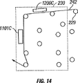
図14に、第4の駆動ローラ229、第1の乾燥バンク1200C、及び第2の乾燥バンク1101Cを含む第3の乾燥ゾーン230の模式図が例示されている。本発明の実施形態では、第1の乾燥バンク1200C及び第2の乾燥バンク1101Cが約50℃の熱風を送ることができるが、本開示から当業者に明らかなように熱風の温度を様々に変更することができる。
FIG. 14 illustrates a schematic diagram of the
図15に、第5の駆動ローラ235、第1の乾燥バンク1200D、及び第2の乾燥バンク1101Dを含む第4の乾燥ゾーン236の模式図が例示されている。本発明の実施形態では、第1の乾燥バンク1200D及び第2の乾燥バンク1101Dが約50℃の熱風を送ることができるが、本開示から当業者に明らかなように熱風の温度を様々に変更することができる。
FIG. 15 illustrates a schematic diagram of a
図16に、粘着ローラ1600及び青色ポリマーローラ1601を含む第1の清浄ユニット204の模式図が例示されている。本発明の実施形態では、青色ポリマーローラ1601が基板242の上面及び底面に接触して微粒子/異物を吸着する。
FIG. 16 illustrates a schematic diagram of the
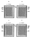
図17(A)‐図17(D)に、適切に見当合わせされた本発明の実施形態のカーボン層に対する絶縁層の印刷を示す模式図が例示されている。図17(A)‐図17(D)がそれぞれ、センサシート2106の左上、右上、左下、及び右下を表していることに留意されたい。図21Aに例示されているマーカーがセンサシートには示されていない。本発明の一実施形態では、カーボン印刷ステーション103で、基板242上の矩形のカーボン線1703によって囲まれた矩形の中実カーボン1700を含むカーボン層を印刷する。後続の印刷サイクルにおいて、絶縁印刷ステーション104で、矩形の中実カーボン1700と矩形のカーボン線1703の間の基板242に矩形の絶縁線1701を印刷する。4つ全ての角部でカーボン層に対する絶縁層の見当合わせが適切な場合、コーティングされていない基板242が矩形の絶縁線1701と矩形の中実カーボン1700との間に存在しないのが普通である。カーボン層に対する絶縁層の見当合わせは、操作者が手動でチェックする、或いは一実施形態では基板のそれぞれの角部に向けられたカメラを含む第2の視覚センサ222を用いてチェックすることができる。これは通常、印刷運転開始の初期設定の一部である。操作者は、TVのスクリーンで互いに近接した基板の4つ全ての角部を観察することができる。次いで、操作者は、この初期設定の際(そして、印刷工程の残りの工程の際)にカーボンに対する絶縁の見当合わせを目で確認し、絶縁印刷とカーボン印刷の見当合わせに必要なあらゆる調節を行うことができる。ウエブビューア222(例えば、基板カードの4つの角部の上に向けられた4つのカメラを含む)が各カードの4つの角部のそれぞれのスナップショットを表示するために撮影及び移動することを理解されたい。ウエブが装置を移動する時にカメラの下側の基板が絶えず変わっていくため、それぞれのカードの角部はほんの一瞬表示されるだけである。このシステムにより、操作者が、カーボンに対する絶縁の見当合わせの調節の効果を瞬時に確認することができる。操作者が行うことができる調節には、限定するものではないが、スクリーン印刷のストローク、スナップ高さ、スキージ圧力、Y方向に対するスクリーンの位置、θに対するスクリーンの位置が含まれる。この印刷ステーション及び他の印刷ステーションに対してビューア見当合わせを設定したら(ビューア228及び234を用いて)、内部X方向自動見当合わせシステム(マーク2107及び2108を用いて)及びY方向自動見当合わせシステム(例えば、マーク2101‐2104を用いる位置237A、237B、及び237Cにある見当合わせシステム)により、印刷中にX方向及びY方向の見当合わせを自動的に補正することができる。本開示から当業者には明らかなように、マーク2101‐2104及び2107‐2108を用いるのに加えて或いは別法として、X方向及びY方向の自動見当合わせに、図17(A)‐図20(D)に示されているマーク1700‐1703を用いることができる。
FIGS. 17A-17D illustrate schematic diagrams illustrating the printing of an insulating layer on a carbon layer of an embodiment of the present invention that is properly registered. Note that FIGS. 17A to 17D represent the upper left, upper right, lower left, and lower right of the
図18に、絶縁アートワークがカーボンアートワークよりも印刷方向に長い見当合わせが不適切な本発明の実施形態のカーボン層に対する絶縁層の図が例示されている。このような不適切な見当合わせは、カーボンと絶縁のスクリーンが同じ方向に同じ大きさであっても、基板の伸長またはスクリーンのストロークが各ステージで異なることにより起こり得る(スクリーンのストロークが遅いと、基板ウエブの移動方向に沿ったアートワーク印刷が比較的長くなる)。図18(A)‐図18(D)がそれぞれ、センサシート2106の左上、右上、左下、及び右下を表していることに留意されたい。4つの角部の1つでカーボン層に対する絶縁層の見当合わせが適当でない場合、矩形の絶縁線1701と矩形の中実カーボン1700との間でコーティングされていない基板242を観察することができる。カーボン層に対する絶縁層の見当合わせは、使用者が第2の視覚センサ222を用いて手動でチェックすることができる。
FIG. 18 illustrates a diagram of an insulating layer versus carbon layer in an embodiment of the present invention where the insulating artwork is inadequately registered in the printing direction than the carbon artwork. Such inadequate registration can occur because the carbon and insulating screens are the same size in the same direction, but the substrate stretches or the screen strokes are different at each stage (if the screen stroke is slow The artwork printing along the direction of movement of the substrate web is relatively long). It should be noted that FIGS. 18A to 18D represent the upper left, upper right, lower left, and lower right of the
図19に、絶縁印刷のアートワークがカーボン印刷のアートワークよりも短い見当合わせが不適切な本発明の実施形態のカーボン層に対する絶縁層の図が例示されている(例えば、絶縁印刷のスクリーンストロークがカーボン印刷のスクリーンストロークよりも長い、または絶縁スクリーンがカーボン印刷ステーションのスクリーンよりも短い場合に起こり得る)。図19(A)‐図19(D)がそれぞれ、センサシート2106の左上、右上、左下、及び右下を示していることを理解されたい。4つの角部の1つでカーボン層に対する絶縁層の見当合わせが不適切な場合、矩形の絶縁線1701と矩形の中実カーボン1700との間でコーティングされていない基板242を観察することができる。カーボン層に対する絶縁層の見当合わせは、操作者が第2の視覚センサ222を用いて手動でチェックすることができる。図20(A)‐図20(D)に、第2のビューガイド2002(図21Aを参照)の印刷の工程の結果を示す模式的な線図が示されている。第2のビューガイド2002は、矩形の中実カーボン1700、矩形の中空絶縁線1701、矩形の中空カーボン1703、第1の酵素層の中実の矩形2000、第2の酵素層の中実の矩形2001、及びコーティングされていない基板242を含む。場合によっては、セクション6(第2の酵素印刷の後)で、このような印刷を検査システム237などの自動連続検査システムによって製造中に使用することもできる。連続的な見当合わせは、通常は、Y方向における位置237A、237B及び237Cにある見当合わせシステム(不図示)及びX方向のマーク2105(図21Aを参照)を向いた見当合わせ制御システムによって実施される。
FIG. 19 illustrates an illustration of an insulating layer versus carbon layer of an embodiment of the present invention in which the insulating printed artwork is shorter than the carbon printed artwork and is improperly registered (eg, the screen stroke of the insulating printing). May be longer than the carbon printing screen stroke or the insulating screen is shorter than the carbon printing station screen). It should be understood that FIGS. 19A to 19D show the upper left, upper right, lower left, and lower right of the
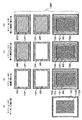
図21Aにセンサシートの例が示されている。このセンサシートは、第1のビューガイド2100及び第2のビューガイド2002、第1のY方向見当合わせマーク2101、第2のY方向マーク2102、第3のY方向マーク2103、第4のY方向マーク2104、及びX方向の見当合わせマーク2105を備えている。X方向見当合わせマーク2105は、カーボンX方向見当合わせマーク2107及び絶縁X方向見当合わせマーク2108を含むことに留意されたい。図21Bに、カーボンX方向見当合わせマーク2107及び第2のビューガイド2202を備えたセンサシート2106の一列を示す図が示されている。図21Cに、絶縁X方向見当合わせマーク2108及び第2のビューガイド2002を備えたセンサシート2106内の一列を示す図が示されている。絶縁X方向マーク2108は、図21Cに例示されているように、カーボンX方向見当合わせマーク2107を完全に覆い、これにより、元のカーボンマーク2107の上に開始点(マーク2108の左側の縁)を提供する。つまり、後に形成される全ての層が、カーボン層ではなく第2の印刷層(この場合は絶縁層)に対して印刷される。これは、第2及びそれに続くスクリーンアートワークの寸法がX方向(ウエブに沿った方向)で第1のスクリーンアートワークの寸法よりも長い場合に有益である。
FIG. 21A shows an example of a sensor sheet. The sensor sheet includes a
図20(A)‐図20(D)に、印刷ガイドの1つの角部が印刷される順に示されている。カーボン印刷ステーション103のセクション3で、矩形の中実カーボン1700がそれを取り囲む矩形のカーボン線1703と共に印刷される。絶縁印刷ステーション1104のセクション4で、矩形の絶縁線1701が、矩形の中実カーボン1700と矩形のカーボン線1703との間に印刷される。カーボンに対する絶縁の見当合わせが4つの角部全てで適切である場合、通常は矩形の中実カーボン1700と矩形の絶縁線1701との間にコーティングされていない基板242が存在しない。加えて、絶縁印刷ステーション104のセクション4で、もう2つの矩形の絶縁線1701が矩形の中実カーボン1700の上方に直接印刷される。これらの2つの追加の絶縁線を用いて、絶縁層に対する第1の酵素層2000の見当合わせ及び絶縁層に対する第2の酵素層2001の見当合わせを視覚的に評価する。この評価は、図20(C)及び図20(D)に例示されているように矩形の絶縁線の中に矩形の中実の酵素インキを印刷して行われる。従って、第3及び第4の印刷層を、第1の印刷層ではなく第2の印刷層に対して見当合わせすることができる。これにより、印刷見当合わせに悪影響を与えずに、第1の層と第2の層とのアートワークの大きさの違い(第1の乾燥ゾーン217での加熱及び伸長などにより、第1の印刷ステーションの後で基板が伸長する場合)を許容することができる(X方向の許容範囲は、通常は300μmである)。
20A to 20D show one corner of the printing guide in the order of printing. In section 3 of the
図1及び図2に例示されているように、工程の最後で、印刷されたセンサを含む基板242が巻取りユニット107によって巻き取られ、次いで、湿度の低い環境に配置される例えばプレコパンチ(Preco punch)とすることができるパンチ108に送られる。プレコパンチは、CCD X Y θフローティングパンチ(CCD X, Y, θ Floating Punch)である。プレコパンチ見当合わせシステムは、CCDビジョンシステムを用いて、カーボン印刷ステーションで印刷された「プレコドット(Preco Dots)」を観察し、これによりパンチをカーボン印刷に対して調節し、このパンチでカードを正方形に打ち抜くことができる。これにより、図21Aに例示されているような一連のパンチされたカードが生産される。パンチされたカードは、パンチ108から移送ベルトに排出され、パンチされたカードがこの移送ベルトでバーコードリーダーの下側に移送され、そこでそれぞれのカード上の2つのバーコードが読み取られ、ウエブデータベースに対してカードが合格か不合格かが決定される。不合格のカードは自動または手動で取り出すことができる。次いで、カードは、次の製造ステップのために次々に積み重ねられる。
As illustrated in FIGS. 1 and 2, at the end of the process, the
カーボン印刷ステーション103、絶縁印刷ステーション104、第1の酵素印刷ステーション105、及び第2の酵素印刷ステーション106の全てがそれぞれ、印刷工程ステップの直後に第1の視覚センサ215、第2の視覚センサ222、第3の視覚センサ228、及び第4の視覚センサ234を用いて見当合わせを視覚的に検査する手段を備えている。セクション3‐6のウエブ印刷製造工程のそれぞれのセクションでは、印刷工程の直後にウエブビューアカメラシステムが配置される。図2A‐図2Cのウエブビューア位置を参照されたい。セクション3には2つのカメラ、セクション4‐6にはそれぞれ4つのカメラが設けられている。ウエブビューアカメラは、印刷運転の開始の際にウエブ装置の操作者が用いる手動セットアップ工程の一部である。これらのカメラを用いて、基板242に対するカーボンの整合の初期設定、カーボン層に対する絶縁層の見当合わせ、絶縁層に対する第1の酵素層の見当合わせ、及び絶縁層に対する第2の酵素層の見当合わせを助ける印刷マークを観察する。印刷ガイドが図21Aに例示されている。カーボン印刷の整合のために、第2のビューアガイド2100を用いて、基板242がカーボン印刷ステーション103を通る時にその基板242の縁に対するカーボン印刷の位置を表示する。図21Aに例示されているように、カーボン印刷には前縁と後縁がある。カーボン印刷は、これらの縁が基板の端部に対してカーボン印刷が直角であることを示すまで調節する。個々に印刷された層の見当合わせは、X方向(装置の長さに沿った方向)及びY方向(装置の幅を横断する方法)で行う必要である(図21Aを参照)。X方向の見当合わせは、装置内部見当合わせシステムによって制御される。この制御には、図21A‐図21Cに示されている印刷領域が用いられる。カーボン印刷サイクルで、カーボンX方向見当合わせマーク2107がこの領域に印刷される。絶縁インキを正しい位置に印刷するために絶縁スクリーンを調節できるように、絶縁印刷サイクルが、カーボンX方向見当合わせマーク2107を用いてセンサでカーボン印刷に見当合わせされる。次いで、このために用いるカーボンX方向見当合わせマーク2107の上に絶縁X方向見当合わせマーク2108を印刷し、これを用いて同様の要領で第1の酵素層200及び第2の酵素層201を絶縁印刷に対して適切に見当合わせする。Y方向の見当合わせは、位置237A、237B、及び237Cに配置されるY方向見当合わせシステム(不図示)によって制御される。本発明の一実施形態では、Y方向見当合わせシステムは、ドイツのレオポルドショー(Leopoldshohe)が販売するエルトロマット見当合わせシステム(モデル番号DGC650)とすることができる。Y方向の見当合わせは、図21Aに示されている印刷領域2101‐2104を用いる。カーボン、絶縁、第1の酵素、及び第2の酵素のそれぞれの印刷サイクルで、これらのマークは、後続の印刷をセンサによりY方向に見当合わせできるように印刷される。ウエブデータベースに、印刷中の工程情報が記録される。データベースに記録された情報を、一実施形態では2次元バーコードであるバーコードを用いて個々のカードについて取り出すことができる。ウエブデータベースに保存される典型的な情報が表2に要約されている。ウエブデータベースは、工程パラメータが許容範囲内であるか否かを評価する能力を有し、これを用いてパラメータが許容範囲内であるか否かの基準に基づいてカードを不合格にすることができる。不合格のカードは、手動または自動で後の工程で取り出すことができる。
図22に、ウエブ印刷工程を見当合わせするために用いられるパラメータX、Y、Z、及びθの模式的な線図が示されている。パラメータYは、操作者からウエブ印刷装置の装置側への方向(通常は水平方向)を表す。パラメータXは、巻出しユニット101から巻取りユニット107への方向(通常は水平方向)を表す。パラメータZは、X方向及びY方向に対して垂直な方向(通常は垂直方向)を表す。パラメータθは、Z軸を中心とした角度を表す。本発明の実施形態では、以下のパラメータを用いて、例えば、カーボン印刷ステーション103、絶縁印刷ステーション104、第1の酵素印刷ステーション105、及び第2の酵素印刷ステーション106などの印刷工程を見当合わせする。
FIG. 22 shows a schematic diagram of parameters X, Y, Z, and θ used to register the web printing process. The parameter Y represents the direction (usually the horizontal direction) from the operator to the apparatus side of the web printing apparatus. The parameter X represents the direction (usually the horizontal direction) from the unwinding
本発明の一実施形態では、ウエブ製造工程の生産物は、アートワークで印刷されたカードである。これらのカードは、それぞれが血液サンプル中のグルコースを検出するための電気化学センサ及び関連した接触電極を含むストリップを形成するように互いに対して見当合わせされて印刷されたカーボン層、絶縁層、及び2つの同一の酵素層を含む。このようなストリップは、測定器と共に用いて血中グルコースを自己監視することができる。様々なデザインのストリップを製造することもできる。現在、ウエブは、ライフスキャン社(LifeScan, Inc.)が販売するワンタッチウルトラ測定器(One Touch Ultra meter)に使用するための「ワンタッチウルトラ」ストリップ(「One Touch Ultra」 strips)を製造するようにデザインされている。 In one embodiment of the invention, the product of the web manufacturing process is a card printed with artwork. These cards each have a carbon layer, an insulating layer printed in register with each other to form a strip that includes an electrochemical sensor and associated contact electrodes for detecting glucose in a blood sample, and Contains two identical enzyme layers. Such a strip can be used with a meter to self-monitor blood glucose. Various designs of strips can also be produced. Currently, the web will produce "One Touch Ultra" strips for use in the One Touch Ultra meter sold by LifeScan, Inc. Designed.
図21Aに、生産されたアートワークの模式的な図の例が示されている。この図は、50個のストリップが形成された列を10列含む完成した1つの印刷されたカードを例示している。1つのカードにつき合計500個のストリップが形成されている。印刷の向きも示されている。それぞれが50個のストリップを有する列0から列9を印刷の方向に平行に印刷することにより、列を互いに分離する切断ステップを工程に容易に含めることができる。更に、ウエブの横断方向(印刷方向に対して垂直方向)の印刷品質のばらつきによって生じる欠陥のある列すべてを容易に識別することができる。それぞれの列に数字(バーコードによって識別)が割り振られているため、ウエブ上の特定のシートの特定の列をデータベースを参照して識別することができ、そのシート全てを不合格にするのではなくその特定の列を除去することができる。これにより、使用可能な製品の収量が上がり、製造工程全体の効率が上昇する。
FIG. 21A shows an example of a schematic diagram of the produced artwork. This figure illustrates one completed printed card containing 10 rows with 50 strips formed. A total of 500 strips are formed per card. The orientation of printing is also shown. By printing
可動式の実質的に平坦なスクリーンが、電気化学センサの印刷に使用するインキの種類(固体/液体の組合せ)に適している。可動式の平坦なスクリーンを使用することにより、印刷鮮明度のより良い制御が可能となり、電気化学センサに必要なインキの層の堆積を、グラビア印刷またはシリンダースクリーン印刷よりも厚くできる。連続的なウエブ印刷工程(カーボン、絶縁、酵素)の様々な種類のインキの様々な要求に適した様々な種類のスクリーン(メッシュの糸の直径、糸の間隔、厚み、メッシュ数が異なる様々なメッシュを備えた)が販売されている。 A movable, substantially flat screen is suitable for the type of ink (solid / liquid combination) used to print the electrochemical sensor. The use of a movable flat screen allows for better control of print definition and allows the ink layer deposition required for electrochemical sensors to be thicker than gravure or cylinder screen printing. Various types of screens (mesh thread diameter, thread spacing, thickness, various mesh numbers differing) suitable for various ink requirements of various types of continuous web printing processes (carbon, insulation, enzyme) With mesh) is on sale.
フラットスクリーン、印刷ローラ、基板、及びその基板に対してスクリーンを押圧するスキージの構成のため、利用できる様々なパラメータ(基板に対するスクリーンの角度、スキージの角度、スキージに対するスクリーンの位置、印刷ローラに対するスキージの位置、スナップ距離、並びに基板、スクリーン、及びスキージなどの相対速度)を操作して電気化学センサの印刷工程を最適化することができる。 Due to the configuration of the flat screen, the printing roller, the substrate and the squeegee that presses the screen against the substrate, the various parameters available (screen angle relative to the substrate, squeegee angle, screen position relative to the squeegee, squeegee relative to the printing roller) The position, snap distance, and relative speed of the substrate, screen, squeegee, etc.) to optimize the electrochemical sensor printing process.
電気化学センサを製造するためのウエブ製造工程を簡単に要約すると、工程中に加熱された時及び張力がかかった時にウエブが膨張または伸長する。それぞれの印刷ステーション(例えば、カーボン、絶縁、2つの酵素)には、通常は乾燥ステーションが続いている。インキを効率的に乾燥させるために、乾燥ステーションはかなりの高温(50℃〜140℃)で運転される。更に、それぞれの印刷ステーションを通るウエブの見当合わせを助けるためにウエブを張る。 Briefly summarizing the web manufacturing process for manufacturing electrochemical sensors, the web expands or stretches when heated and tensioned during the process. Each printing station (eg carbon, insulation, two enzymes) is usually followed by a drying station. In order to dry the ink efficiently, the drying station is operated at a fairly high temperature (50 ° C. to 140 ° C.). In addition, the web is stretched to assist in registering the web through each printing station.
基板は、工程中の見当合わせを制御するために張った状態に維持しなければならない。このため、例えば印刷の後にインキを乾燥するべく基板が加熱されるたびに、基板が予測不可能に伸長し、後続の印刷でイメージの大きさがばらついてしまう。 The substrate must be kept taut to control registration during the process. For this reason, for example, every time the substrate is heated to dry the ink after printing, the substrate expands unpredictably, and subsequent printing causes the image size to vary.
それぞれの印刷ステーションで印刷されるイメージの大きさは、複数の因子(ステンシルの大きさ、インキの粘度、ウエブとステンシル/スクリーンの相対速度、その時点での基板の可逆的及び不可逆的な伸長)によって決まる。工程の最後で見たイメージの大きさのばらつき(異なった印刷ステップ間での)が様々であることが分かった。収量の低下は予測不可能であり、予測よりも大きかった。層間のイメージの大きさの不整合がウエブに沿って(X方向)300μmを超えると製品は適切に作動しない。過度のイメージの大きさのばらつきは、ウエブ基板の過度の予測できない伸長(加熱及び引っ張りによる)及び収縮によるものと考えられる。 The size of the image printed at each printing station depends on several factors (stencil size, ink viscosity, web and stencil / screen relative speed, reversible and irreversible elongation of the substrate at that time). It depends on. It has been found that the variation in image size (between different printing steps) seen at the end of the process varies. The yield decline was unpredictable and greater than expected. If the image size mismatch between the layers exceeds 300 μm along the web (X direction), the product will not operate properly. Excessive image size variation is believed to be due to excessive unpredictable stretching (due to heating and pulling) and shrinking of the web substrate.
伸長と張力の問題は、フラットベッド印刷では起こらない。ウエブ工程におけるこの問題を解決するために事前に収縮させた基板を試した。ウエブ工程で用いる前に、基板を約185℃に加熱した。しかしながら、イメージの大きさのばらつきの問題が残り収量が低かった。 Elongation and tension problems do not occur with flatbed printing. In order to solve this problem in the web process, a pre-shrinked substrate was tried. Prior to use in the web process, the substrate was heated to about 185 ° C. However, the problem of variation in image size remained and the yield was low.
ウエブ工程の現在の提案は、基板にイメージを印刷する前に、一例では基板から不可逆的な伸長を実質的に排除するように第1の乾燥または前処理を高温で行うことである。 The current proposal for a web process is to perform a first drying or pretreatment at an elevated temperature prior to printing an image on the substrate, in one example, to substantially eliminate irreversible stretching from the substrate.
ウエブ装置の第1の工程ステーションでは、乾燥バンクで基板を最大160℃まで加熱する。基板の後の工程は、通常は140℃を超えない。 In the first process station of the web apparatus, the substrate is heated up to 160 ° C. in a drying bank. Subsequent steps of the substrate usually do not exceed 140 ° C.
図2Aでは、印刷されていない基板が出合う第1の加熱バンクはホットプレートである。これは、テフロン(登録商標)がコーティングされたプレートであり、ウエブが移動する時に基板に接触し、その基板を持ち上げる。基板の後面に熱が供給される。これは、現在は160℃±4℃の設定温度で行われる。160℃の設定温度は、統計的に最適な寸法管理である。計算値は160.9℃である。バンク2では、基板の前面に160℃±4℃の設定温度で熱風が供給される。計算値は161.29℃である。バンク3では、基板の前面に160℃±4℃の設定温度で熱風が供給される。計算値は161.18℃である。バンク4では、基板の前面に160℃±4℃の設定温度で熱風が供給される。この計算値は160.70℃である。 In FIG. 2A, the first heating bank where unprinted substrates meet is a hot plate. This is a Teflon-coated plate that contacts the substrate as the web moves and lifts the substrate. Heat is supplied to the rear surface of the substrate. This is currently done at a set temperature of 160 ° C. ± 4 ° C. A set temperature of 160 ° C. is statistically optimal dimensional control. The calculated value is 160.9 ° C. In bank 2, hot air is supplied to the front surface of the substrate at a set temperature of 160 ° C. ± 4 ° C. The calculated value is 161.29 ° C. In bank 3, hot air is supplied to the front surface of the substrate at a set temperature of 160 ° C. ± 4 ° C. The calculated value is 161.18 ° C. In the bank 4, hot air is supplied to the front surface of the substrate at a set temperature of 160 ° C. ± 4 ° C. This calculated value is 160.70 ° C.
ウエブの張力及び乾燥工程での加熱により、ウエブ基板が、1アートワーク当たり約0.7mm伸長する。この伸長が、ステーション1を前処理ユニットとして用いて後続の印刷ステーションに先立って基板を安定させる主な理由の1つである。ステーション1で基板を前処理するため、印刷の前に基板から材料の伸長の殆どが取り除かれ、カーボン及び絶縁の列の長さと安定性が改善される。 Due to the tension of the web and the heating in the drying process, the web substrate stretches about 0.7 mm per artwork. This stretching is one of the main reasons for using the station 1 as a pretreatment unit to stabilize the substrate prior to subsequent printing stations. Pretreatment of the substrate at station 1 removes most of the material stretch from the substrate prior to printing, improving the length and stability of the carbon and insulation rows.
本発明の一実施形態では、冷却ローラが乾燥ステーションと後続のスクリーン印刷ステーションとの間に配置されている。冷却ローラは、次のスクリーン上のインキの溶媒(例えば、水)が蒸発するのを制限または防止する温度まで基板を冷却する。従って、基板の加熱によってインキが乾燥してスクリーンが詰まるのを排除または防止する。本発明に従った方法または装置における冷却ローラを、例えば、約7℃〜9℃に冷却された冷却水をそのローラ内に流して冷却し、次いで冷却されたこのローラの上を暖かい基板を移動させる。 In one embodiment of the invention, a cooling roller is disposed between the drying station and the subsequent screen printing station. The cooling roller cools the substrate to a temperature that limits or prevents evaporation of the ink solvent (eg, water) on the next screen. Accordingly, it is possible to eliminate or prevent the ink from drying and clogging the screen by heating the substrate. The cooling roller in the method or apparatus according to the present invention is cooled, for example, by flowing cooling water cooled to about 7 ° C. to 9 ° C. into the roller, and then the warm substrate is moved over the cooled roller. Let
本発明の別の実施形態では、7℃〜9℃の水で内部で冷却される冷却ローラが、水性酵素インキを堆積するために用いられる印刷ステーションの前に配置されている。冷却ローラは、前のインキ堆積(例えば、電極インキの堆積)のための乾燥ステーションを出た直後に基板が冷却ローラ上を回るように配置されている。 In another embodiment of the present invention, a cooling roller that is internally cooled with water at 7 ° C to 9 ° C is placed in front of the printing station used to deposit the aqueous enzyme ink. The cooling roller is positioned so that the substrate runs over the cooling roller immediately after leaving the drying station for the previous ink deposition (eg, electrode ink deposition).
ここに例示及び開示した構造の代わりに同等の構造を用いることができ、本発明の記載した実施形態が請求する発明を実施するためだけに用いられる構造ではないことを理解されたい。加えて、上記した全ての構造が機能を有し、このような構造をその機能を果たすための手段と見なすことができることを理解されたい。 It should be understood that equivalent structures may be used in place of the structures illustrated and disclosed herein, and that the described embodiments of the invention are not the structures used only to practice the claimed invention. In addition, it should be understood that all the structures described above have a function, and such a structure can be considered as a means for performing that function.
本発明の好適な実施形態をここに図示及び開示したが、当業者には、このような実施形態が単なる例であることを理解できよう。当業者には、本発明から逸脱しない様々な変更形態、変形形態、及び置換形態が明らかであろう。ここに開示した本発明の実施形態の様々な代替形態を用いて本発明を実施できることを理解できよう。添付の特許請求の範囲が本発明の範囲を規定し、特許請求の範囲内の方法及び構造並びにこれらの等価物が本発明の範囲内であるものとする。
なお、本発明の好ましい実施態様は以下の通りである。
(1) 基板及びその基板に印刷された少なくとも2つの層を含む電気化学センサの製造方法であって、
前記基板のウエブを、第1の印刷ステーション、第2の印刷ステーション、それらの印刷ステーションの間に配置された乾燥ステーション、及びその乾燥ステーションと前記第2の印刷ステーションとの間に配置された冷却ステーションに移送することを含み、
前記基板が前記第1の印刷ステーションを通過する時に前記基板上に第1の層を印刷し、
前記乾燥ステーションで前記基板上の前記層を乾燥させ、
前記基板が前記第2の印刷ステーションを通過して前記基板上に第2の層を印刷する前に、前記冷却ステーションで前記印刷された基板を冷却することを特徴とする方法。
(2) 前記第1の層が電極層及び試薬層の一方であり、前記第2の層が電極層及び試薬層の他方であることを特徴とする実施態様(1)に記載の方法。
(3) 1または複数の別の印刷ステーションが、乾燥ステーションと、前記印刷された基板のウエブを冷却するための関連冷却ステーションを有することを特徴とする実施態様(1)または(2)に記載の方法。
(4) 1または複数の冷却ステーションが冷却手段を含み、その冷却手段の上を前記基板が通過することを特徴とする実施態様(1)乃至(3)の何れかに記載の方法。
(5) 前記冷却手段の温度が制御可能であることを特徴とする実施態様(1)乃至(4)の何れかに記載の方法。
(6) 前記冷却手段を、前記冷却ステーションの前の前記乾燥ステーションの温度よりも低い温度まで冷却することを特徴とする実施態様(1)乃至(5)の何れかに記載の方法。
(7) 前記冷却手段が、後続の印刷ステーションにおけるインキの湿度分が、ある温度であって、その温度以下では、その印刷ステーションを前記基板が通過する時と実質的に同じに維持される温度まで前記基板ウエブを冷却することを特徴とする実施態様(1)乃至(6)の何れかに記載の方法。
(8) 前記冷却手段または前記冷却ステーションを離れる時の前記基板の温度を制御するべく前記冷却手段の温度を制御可能であることを特徴とする実施態様(4)乃至(7)の何れかに記載の方法。
(9) 前記冷却手段または前記冷却ステーションを離れる時の前記基板の温度を制御するべく前記基板が前記冷却手段の近傍に存在する時間を制御可能であることを特徴とする実施態様(4)乃至(8)の何れかに記載の方法。
(10) 冷却後の時点の前記基板ウエブの温度を用いて、前記冷却手段を通過する時の前記基板ウエブの後の部分の冷却を制御することを特徴とする実施態様(4)乃至(8)の何れかに記載の方法。
(11) 前記基板の温度が室温よりも低い温度または室温と実質的に等しい温度であることを特徴とする実施態様(10)に記載の方法。
(12) 前記基板の温度が露点温度よりも高いことを特徴とする実施態様(11)に記載の方法。
(13) 前記冷却手段を室温またはそれ以下の温度まで冷却することを特徴とする実施態様(4)乃至(12)の何れかに記載の方法。
(14) 前記冷却手段を約17℃〜19℃よりも低い温度まで冷却することを特徴とする実施態様(4)乃至(13)の何れかに記載の方法。
(15) 前記冷却手段を約7℃〜9℃まで冷却することを特徴とする実施態様(14)に記載の方法。
(16) 前記冷却手段がローラを含み、そのローラの上を前記基板が通過することを特徴とする実施態様(4)乃至(15)の何れかに記載の方法。
(17) 前記冷却手段が冷却水と共に供給されることを特徴とする実施態様(4)乃至(16)の何れかに記載の方法。
(18) 前記冷却手段の温度を制御するべく冷却水の流速及び/または温度を制御することを特徴とする実施態様(4)乃至(17)の何れかに記載の方法。
(19) 最後の印刷ステーションの後に最後の乾燥ステーションが続き、その最後の乾燥ステーションの後に最後の冷却ステーションが続くことを特徴とする実施態様(1)乃至(18)の何れかに記載の方法。
(20) 第1の印刷ステーションで導電インキを印刷し、第2の印刷ステーションで絶縁インキを印刷し、第3の印刷ステーションで試薬インキを印刷することを特徴とする実施態様(1)乃至(19)の何れかに記載の方法。
(21) 第4の印刷ステーションで試薬インキを印刷することを特徴とする実施態様(20)に記載の方法。
(22) 上記した順序で前記インキを印刷することを特徴とする実施態様(20)または(21)に記載の方法。
(23) 1または複数の乾燥ステーションが、約40℃〜150℃の範囲で動作する前記基板を乾燥させるための1または複数のヒーターを含むことを特徴とする実施態様(1)乃至(22)の何れかに記載の方法。
(24) 1または複数の乾燥ステーションが、約50℃〜140℃の範囲で動作する前記基板を乾燥させるための1または複数のヒーターを含むことを特徴とする実施態様(1)乃至(23)の何れかに記載の方法。
(25) 基板及びその基板に印刷された少なくとも2つの層を含む電気化学センサを製造するための装置であって、
前記基板のウエブを第1の印刷ステーション、第2の印刷ステーション、それらの印刷ステーションの間に配置された乾燥ステーション、及びその乾燥ステーションと前記第2の印刷ステーションとの間に配置された冷却ステーションに移送するための移送手段を含み、
第1の層が、前記基板が前記第1の印刷ステーションを通過する時に前記基板に印刷され、この層が前記乾燥ステーションで前記基板上で乾燥され、
前記印刷された基板が第2の印刷ステーションを通過して前記基板上に第2の層が印刷される前に、前記印刷された基板が前記冷却ステーションで冷却されることを特徴とする装置。
(26) 前記第1の層が電極層及び試薬層の一方であり、前記第2の層が電極層及び試薬層の他方であることを特徴とする実施態様(25)に記載の装置。
(27) 1または複数の別の印刷ステーションが、乾燥ステーションと、前記印刷された基板のウエブを冷却するための関連冷却ステーションを有することを特徴とする実施態様(25)または(26)に記載の装置。
(28) 1または複数の冷却ステーションが冷却手段を含み、その冷却手段の上を前記基板が通過することを特徴とする実施態様(25)乃至(27)の何れかに記載の装置。
(29) 前記冷却手段の温度が制御可能であることを特徴とする実施態様(25)乃至(28)の何れかに記載の装置。
(30) 前記冷却手段を、前記冷却ステーションの前の前記乾燥ステーションの温度よりも低い温度まで冷却することを特徴とする実施態様(28)乃至(30)の何れかに記載の装置。
(31) 前記冷却手段が、ある温度であって、その温度以下では、後続の印刷ステーションにおける前記インキの湿度分がその印刷ステーションを前記基板が通過する時と実質的に同じに維持される温度まで前記基板ウエブを冷却することを特徴とする実施態様(28)乃至(30)の何れかに記載の装置。
(32) 前記冷却手段または前記冷却ステーションを離れる時の前記基板の温度を制御するべく前記冷却手段の温度を制御可能であることを特徴とする実施態様(28)乃至(31)の何れかに記載の装置。
(33) 前記冷却手段または前記冷却ステーションを離れる時の前記基板の温度を制御するべく前記基板が前記冷却手段の近傍に存在する時間を制御可能であることを特徴とする実施態様(28)乃至(32)の何れかに記載の装置。
(34) 冷却後の時点の前記基板ウエブの温度を用いて、前記冷却手段を通過する時の前記基板ウエブの後の部分の冷却を制御することを特徴とする実施態様(28)乃至(33)の何れかに記載の装置。
(35) 前記冷却手段を室温またはそれ以下の温度まで冷却することを特徴とする実施態様(28)乃至(34)の何れかに記載の装置。
(36) 前記冷却手段を約17℃〜19℃よりも低い温度まで冷却することを特徴とする実施態様(28)乃至(34)の何れかに記載の装置。
(37) 前記冷却手段を約7℃〜9℃まで冷却することを特徴とする実施態様(36)に記載の装置。
(38) 前記冷却手段がローラを含み、そのローラの上を前記基板が通過することを特徴とする実施態様(28)乃至(37)の何れかに記載の装置。
(39) 前記冷却手段が冷却水と共に供給されることを特徴とする実施態様(28)乃至(38)の何れかに記載の装置。
(40) 前記冷却手段の温度を制御するべく冷却水の流速及び/または温度を制御することを特徴とする実施態様(28)乃至(39)の何れかに記載の装置。
(41) 最後の印刷ステーションの後に最後の乾燥ステーションが続き、その最後の乾燥ステーションの後に最後の冷却ステーションが続くことを特徴とする実施態様(28)乃至(40)の何れかに記載の装置。
(42) 第1の印刷ステーションで導電インキを印刷し、第2の印刷ステーションで絶縁インキを印刷し、第3の印刷ステーションで試薬インキを印刷することを特徴とする実施態様(25)乃至(41)の何れかに記載の装置。
(43) 第4の印刷ステーションで試薬インキを印刷することを特徴とする実施態様(42)に記載の装置。
(44) 上記した順序で前記インキを印刷することを特徴とする実施態様(42)または(43)に記載の装置。
(45) 1または複数の乾燥ステーションが、約40℃〜150℃の範囲で動作する前記基板を乾燥させるための1または複数のヒーターを含むことを特徴とする実施態様(25)乃至(44)の何れかに記載の装置。
(46) 1または複数の乾燥ステーションが、約50℃〜140℃の範囲で動作する前記基板を乾燥させるための1または複数のヒーターを含むことを特徴とする実施態様(25)乃至(45)の何れかに記載の装置。
(47) 実施態様(1)乃至(24)または(49)の何れかに従った方法で製造された電気化学センサ。
(48) 実施態様(25)乃至(46)または(50)の何れかに従った方法で製造された電気化学センサ。
(49) 実質的に添付の図面に例示された方法、及び/または実質的に添付の図面を参照して説明した方法。
(50) 実質的に添付の図面に例示された装置、及び/または実質的に添付の図面を参照して説明した装置。
While preferred embodiments of the present invention have been illustrated and disclosed herein, those skilled in the art will appreciate that such embodiments are merely examples. Various modifications, variations, and substitutions will be apparent to those skilled in the art without departing from the invention. It will be appreciated that the invention can be practiced with various alternatives to the embodiments of the invention disclosed herein. It is intended that the appended claims define the scope of the invention and that methods and structures within the scope of the claims and their equivalents be included within the scope of the invention.
The preferred embodiments of the present invention are as follows.
(1) A method for producing an electrochemical sensor comprising a substrate and at least two layers printed on the substrate,
A web of the substrate is subjected to a first printing station, a second printing station, a drying station disposed between the printing stations, and a cooling disposed between the drying station and the second printing station. Including transferring to a station,
Printing a first layer on the substrate as the substrate passes through the first printing station;
Drying the layer on the substrate at the drying station;
A method of cooling the printed substrate at the cooling station before the substrate passes the second printing station and prints a second layer on the substrate.
(2) The method according to embodiment (1), wherein the first layer is one of an electrode layer and a reagent layer, and the second layer is the other of the electrode layer and the reagent layer.
(3) The embodiment (1) or (2), wherein one or more separate printing stations have a drying station and an associated cooling station for cooling the printed substrate web. the method of.
(4) The method according to any one of the embodiments (1) to (3), wherein one or more cooling stations include cooling means, and the substrate passes over the cooling means.
(5) The method according to any one of the embodiments (1) to (4), wherein the temperature of the cooling means is controllable.
(6) The method according to any one of the embodiments (1) to (5), wherein the cooling means is cooled to a temperature lower than the temperature of the drying station before the cooling station.
(7) The cooling means is a temperature at which the humidity of the ink in the subsequent printing station is a certain temperature, and below that temperature, is maintained substantially the same as when the substrate passes through the printing station. The method according to any one of the embodiments (1) to (6), wherein the substrate web is cooled to a minimum.
(8) In any of the embodiments (4) to (7), the temperature of the cooling means can be controlled to control the temperature of the substrate when leaving the cooling means or the cooling station. The method described.
(9) Embodiments (4) to (4) characterized in that the time during which the substrate exists in the vicinity of the cooling means can be controlled to control the temperature of the substrate when leaving the cooling means or the cooling station. The method according to any one of (8).
(10) The embodiments (4) to (8), wherein the cooling of the portion after the substrate web when passing through the cooling means is controlled using the temperature of the substrate web at the time after cooling. ).
(11) The method according to embodiment (10), wherein the temperature of the substrate is lower than room temperature or substantially equal to room temperature.
(12) The method according to embodiment (11), wherein the temperature of the substrate is higher than a dew point temperature.
(13) The method according to any one of embodiments (4) to (12), wherein the cooling means is cooled to a temperature of room temperature or lower.
(14) The method according to any one of embodiments (4) to (13), wherein the cooling means is cooled to a temperature lower than about 17 ° C to 19 ° C.
(15) The method according to embodiment (14), wherein the cooling means is cooled to about 7 ° C to 9 ° C.
(16) The method according to any one of embodiments (4) to (15), wherein the cooling means includes a roller, and the substrate passes over the roller.
(17) The method according to any one of embodiments (4) to (16), wherein the cooling means is supplied together with cooling water.
(18) The method according to any one of embodiments (4) to (17), wherein the flow rate and / or temperature of cooling water is controlled to control the temperature of the cooling means.
(19) The method according to any one of embodiments (1) to (18), characterized in that the last printing station is followed by the last drying station, and the last drying station is followed by the last cooling station. .
(20) Embodiments (1) to (1), wherein conductive ink is printed at the first printing station, insulating ink is printed at the second printing station, and reagent ink is printed at the third printing station. The method according to any one of 19).
(21) The method according to embodiment (20), wherein the reagent ink is printed at a fourth printing station.
(22) The method according to embodiment (20) or (21), wherein the inks are printed in the order described above.
(23) The embodiments (1) to (22), wherein the one or more drying stations include one or more heaters for drying the substrate operating in the range of about 40 ° C. to 150 ° C. The method in any one of.
(24) The embodiments (1) to (23), wherein the one or more drying stations include one or more heaters for drying the substrate operating in the range of about 50 ° C. to 140 ° C. The method in any one of.
(25) An apparatus for manufacturing an electrochemical sensor comprising a substrate and at least two layers printed on the substrate,
A first printing station; a second printing station; a drying station disposed between the printing stations; and a cooling station disposed between the drying station and the second printing station. Including transport means for transporting to
A first layer is printed on the substrate as the substrate passes through the first printing station, and this layer is dried on the substrate at the drying station;
The apparatus, wherein the printed substrate is cooled at the cooling station before the printed substrate passes through a second printing station and a second layer is printed on the substrate.
(26) The device according to embodiment (25), wherein the first layer is one of an electrode layer and a reagent layer, and the second layer is the other of the electrode layer and the reagent layer.
(27) In an embodiment (25) or (26), wherein one or more other printing stations have a drying station and an associated cooling station for cooling the printed substrate web. Equipment.
(28) The apparatus according to any one of embodiments (25) to (27), wherein one or more cooling stations include cooling means, and the substrate passes over the cooling means.
(29) The apparatus according to any one of embodiments (25) to (28), wherein the temperature of the cooling means is controllable.
(30) The apparatus according to any one of embodiments (28) to (30), wherein the cooling means is cooled to a temperature lower than a temperature of the drying station before the cooling station.
(31) The temperature at which the cooling means is at a certain temperature and below that temperature, the humidity of the ink in a subsequent printing station is maintained substantially the same as when the substrate passes through the printing station. The apparatus according to any one of the embodiments (28) to (30), wherein the substrate web is cooled to the point.
(32) In any of the embodiments (28) to (31), the temperature of the cooling means can be controlled to control the temperature of the substrate when leaving the cooling means or the cooling station. The device described.
(33) The embodiments (28) to (28), wherein the time during which the substrate exists in the vicinity of the cooling means can be controlled to control the temperature of the substrate when leaving the cooling means or the cooling station. The apparatus according to any one of (32).
(34) The embodiments (28) to (33), wherein the temperature of the substrate web at the time after cooling is used to control the cooling of the rear portion of the substrate web when passing through the cooling means. ).
(35) The apparatus according to any one of embodiments (28) to (34), wherein the cooling means is cooled to room temperature or lower.
(36) The apparatus according to any one of embodiments (28) to (34), wherein the cooling means is cooled to a temperature lower than about 17 ° C to 19 ° C.
(37) The apparatus according to embodiment (36), wherein the cooling means is cooled to about 7 ° C to 9 ° C.
(38) The apparatus according to any one of embodiments (28) to (37), wherein the cooling means includes a roller, and the substrate passes over the roller.
(39) The apparatus according to any one of embodiments (28) to (38), wherein the cooling means is supplied together with cooling water.
(40) The apparatus according to any one of embodiments (28) to (39), wherein the flow rate and / or temperature of the cooling water is controlled to control the temperature of the cooling means.
41. An apparatus according to any of embodiments 28 to 40, wherein the last printing station is followed by a last drying station, and the last drying station is followed by a last cooling station. .
(42) Embodiments (25) to (25), wherein conductive ink is printed at the first printing station, insulating ink is printed at the second printing station, and reagent ink is printed at the third printing station. 41) The apparatus according to any one of the above.
(43) The apparatus according to embodiment (42), wherein the reagent ink is printed at the fourth printing station.
(44) The apparatus according to the embodiment (42) or (43), wherein the ink is printed in the order described above.
(45) Embodiments (25) to (44), wherein the one or more drying stations include one or more heaters for drying the substrate operating in the range of about 40 ° C to 150 ° C. The apparatus in any one of.
(46) Embodiments (25) to (45), wherein the one or more drying stations include one or more heaters for drying the substrate operating in the range of about 50 ° C to 140 ° C. The apparatus in any one of.
(47) An electrochemical sensor manufactured by the method according to any one of the embodiments (1) to (24) or (49).
(48) An electrochemical sensor manufactured by the method according to any one of the embodiments (25) to (46) or (50).
(49) A method substantially as illustrated in the accompanying drawings and / or substantially as described with reference to the accompanying drawings.
(50) Apparatus substantially as illustrated in the accompanying drawings and / or apparatus substantially described with reference to the accompanying drawings.
Claims (42)
前記基板のウエブを、第1の印刷ステーション、第2の印刷ステーション、それらの印刷ステーションの間に配置された乾燥ステーション、及びその乾燥ステーションと前記第2の印刷ステーションとの間に配置された冷却ステーションに移送することを含み、
前記基板が前記第1の印刷ステーションを通過する時に前記基板上に第1の層を印刷し、
前記乾燥ステーションで前記基板上の前記層を乾燥させ、
前記基板が前記第2の印刷ステーションを通過して前記基板上に第2の層を印刷する前に、前記冷却ステーションで前記印刷された基板を冷却することを含み、
前記冷却ステーションが、前記基板を隣接して通過させる冷却装置を含む、
ことを特徴とする、方法。In a method for producing an electrochemical sensor comprising a substrate and at least two layers printed on the substrate,
A web of the substrate is subjected to a first printing station, a second printing station, a drying station disposed between the printing stations, and a cooling disposed between the drying station and the second printing station. Including transferring to a station,
Printing a first layer on the substrate as the substrate passes through the first printing station;
Drying the layer on the substrate at the drying station;
Cooling the printed substrate at the cooling station before the substrate passes the second printing station and prints a second layer on the substrate;
The cooling station includes a cooling device that passes the substrate adjacently;
A method characterized by that.
前記基板のウエブを第1の印刷ステーション、第2の印刷ステーション、それらの印刷ステーションの間に配置された乾燥ステーション、及びその乾燥ステーションと前記第2の印刷ステーションとの間に配置された冷却ステーションに移送するための移送手段を含み、
第1の層が、前記基板が前記第1の印刷ステーションを通過する時に前記基板に印刷され、この層が前記乾燥ステーションで前記基板上で乾燥され、
前記印刷された基板が第2の印刷ステーションを通過して前記基板上に第2の層が印刷される前に、前記印刷された基板が前記冷却ステーションで冷却され、
前記冷却ステーションが、前記基板を隣接して通過させる冷却装置を含む、
ことを特徴とする、装置。In an apparatus for manufacturing an electrochemical sensor comprising a substrate and at least two layers printed on the substrate,
A first printing station; a second printing station; a drying station disposed between the printing stations; and a cooling station disposed between the drying station and the second printing station. Including transfer means for transferring to
A first layer is printed on the substrate as the substrate passes through the first printing station, and this layer is dried on the substrate at the drying station;
Before the printed substrate passes through a second printing station and a second layer is printed on the substrate, the printed substrate is cooled at the cooling station;
The cooling station includes a cooling device for passing the substrate adjacently;
A device characterized by that.
Applications Claiming Priority (5)
| Application Number | Priority Date | Filing Date | Title |
|---|---|---|---|
| US42222602P | 2002-10-30 | 2002-10-30 | |
| US42223002P | 2002-10-30 | 2002-10-30 | |
| US43668302P | 2002-12-27 | 2002-12-27 | |
| US43668502P | 2002-12-27 | 2002-12-27 | |
| PCT/GB2003/004652 WO2004040005A1 (en) | 2002-10-30 | 2003-10-30 | Cooling stations for use in a web printing process for the manufacture of electrochemical sensors |
Publications (3)
| Publication Number | Publication Date |
|---|---|
| JP2006504944A JP2006504944A (en) | 2006-02-09 |
| JP2006504944A5 JP2006504944A5 (en) | 2010-02-25 |
| JP4650875B2 true JP4650875B2 (en) | 2011-03-16 |
Family
ID=32234372
Family Applications (6)
| Application Number | Title | Priority Date | Filing Date |
|---|---|---|---|
| JP2004547783A Expired - Fee Related JP4574353B2 (en) | 2002-10-30 | 2003-10-30 | Apparatus and method for controlling registration of printing steps in a continuous process of manufacturing an electrochemical sensor |
| JP2004547809A Expired - Fee Related JP4642472B2 (en) | 2002-10-30 | 2003-10-30 | Humidification of enzyme printing in a continuous process to produce electrochemical sensors |
| JP2004547803A Expired - Fee Related JP4633466B2 (en) | 2002-10-30 | 2003-10-30 | Manufacture of electrochemical sensors by movable flat screen printing |
| JP2004547786A Expired - Fee Related JP4650876B2 (en) | 2002-10-30 | 2003-10-30 | Pretreatment of substrates in a continuous process for the production of electrochemical sensors |
| JP2004547782A Expired - Fee Related JP4624107B2 (en) | 2002-10-30 | 2003-10-30 | Manufacturing method of electrochemical sensor |
| JP2004547779A Expired - Fee Related JP4650875B2 (en) | 2002-10-30 | 2003-10-30 | Cooling station for use in web printing processes to produce electrochemical sensors |
Family Applications Before (5)
| Application Number | Title | Priority Date | Filing Date |
|---|---|---|---|
| JP2004547783A Expired - Fee Related JP4574353B2 (en) | 2002-10-30 | 2003-10-30 | Apparatus and method for controlling registration of printing steps in a continuous process of manufacturing an electrochemical sensor |
| JP2004547809A Expired - Fee Related JP4642472B2 (en) | 2002-10-30 | 2003-10-30 | Humidification of enzyme printing in a continuous process to produce electrochemical sensors |
| JP2004547803A Expired - Fee Related JP4633466B2 (en) | 2002-10-30 | 2003-10-30 | Manufacture of electrochemical sensors by movable flat screen printing |
| JP2004547786A Expired - Fee Related JP4650876B2 (en) | 2002-10-30 | 2003-10-30 | Pretreatment of substrates in a continuous process for the production of electrochemical sensors |
| JP2004547782A Expired - Fee Related JP4624107B2 (en) | 2002-10-30 | 2003-10-30 | Manufacturing method of electrochemical sensor |
Country Status (14)
| Country | Link |
|---|---|
| EP (6) | EP1586222B1 (en) |
| JP (6) | JP4574353B2 (en) |
| KR (6) | KR101106942B1 (en) |
| AT (6) | ATE489842T1 (en) |
| AU (6) | AU2003278365B2 (en) |
| CA (6) | CA2504311C (en) |
| DE (6) | DE60335142D1 (en) |
| DK (1) | DK1579204T3 (en) |
| ES (6) | ES2315542T3 (en) |
| HK (6) | HK1076865A1 (en) |
| MX (5) | MXPA05004641A (en) |
| PT (1) | PT1579204E (en) |
| SI (1) | SI1579204T1 (en) |
| WO (6) | WO2004040005A1 (en) |
Families Citing this family (88)
| Publication number | Priority date | Publication date | Assignee | Title |
|---|---|---|---|---|
| US6036924A (en) | 1997-12-04 | 2000-03-14 | Hewlett-Packard Company | Cassette of lancet cartridges for sampling blood |
| US6391005B1 (en) | 1998-03-30 | 2002-05-21 | Agilent Technologies, Inc. | Apparatus and method for penetration with shaft having a sensor for sensing penetration depth |
| US8641644B2 (en) | 2000-11-21 | 2014-02-04 | Sanofi-Aventis Deutschland Gmbh | Blood testing apparatus having a rotatable cartridge with multiple lancing elements and testing means |
| ATE485766T1 (en) | 2001-06-12 | 2010-11-15 | Pelikan Technologies Inc | ELECTRICAL ACTUATING ELEMENT FOR A LANCET |
| US9226699B2 (en) | 2002-04-19 | 2016-01-05 | Sanofi-Aventis Deutschland Gmbh | Body fluid sampling module with a continuous compression tissue interface surface |
| US7749174B2 (en) | 2001-06-12 | 2010-07-06 | Pelikan Technologies, Inc. | Method and apparatus for lancet launching device intergrated onto a blood-sampling cartridge |
| US9427532B2 (en) | 2001-06-12 | 2016-08-30 | Sanofi-Aventis Deutschland Gmbh | Tissue penetration device |
| EP1404234B1 (en) | 2001-06-12 | 2011-02-09 | Pelikan Technologies Inc. | Apparatus for improving success rate of blood yield from a fingerstick |
| US7025774B2 (en) | 2001-06-12 | 2006-04-11 | Pelikan Technologies, Inc. | Tissue penetration device |
| DE60234598D1 (en) | 2001-06-12 | 2010-01-14 | Pelikan Technologies Inc | SELF-OPTIMIZING LANZET DEVICE WITH ADAPTANT FOR TEMPORAL FLUCTUATIONS OF SKIN PROPERTIES |
| US8337419B2 (en) | 2002-04-19 | 2012-12-25 | Sanofi-Aventis Deutschland Gmbh | Tissue penetration device |
| US7981056B2 (en) | 2002-04-19 | 2011-07-19 | Pelikan Technologies, Inc. | Methods and apparatus for lancet actuation |
| US7682318B2 (en) | 2001-06-12 | 2010-03-23 | Pelikan Technologies, Inc. | Blood sampling apparatus and method |
| US9795747B2 (en) | 2010-06-02 | 2017-10-24 | Sanofi-Aventis Deutschland Gmbh | Methods and apparatus for lancet actuation |
| US7674232B2 (en) | 2002-04-19 | 2010-03-09 | Pelikan Technologies, Inc. | Method and apparatus for penetrating tissue |
| US8579831B2 (en) | 2002-04-19 | 2013-11-12 | Sanofi-Aventis Deutschland Gmbh | Method and apparatus for penetrating tissue |
| US9795334B2 (en) | 2002-04-19 | 2017-10-24 | Sanofi-Aventis Deutschland Gmbh | Method and apparatus for penetrating tissue |
| US7175642B2 (en) | 2002-04-19 | 2007-02-13 | Pelikan Technologies, Inc. | Methods and apparatus for lancet actuation |
| US7547287B2 (en) | 2002-04-19 | 2009-06-16 | Pelikan Technologies, Inc. | Method and apparatus for penetrating tissue |
| US7976476B2 (en) | 2002-04-19 | 2011-07-12 | Pelikan Technologies, Inc. | Device and method for variable speed lancet |
| US7331931B2 (en) | 2002-04-19 | 2008-02-19 | Pelikan Technologies, Inc. | Method and apparatus for penetrating tissue |
| US7297122B2 (en) | 2002-04-19 | 2007-11-20 | Pelikan Technologies, Inc. | Method and apparatus for penetrating tissue |
| US7232451B2 (en) | 2002-04-19 | 2007-06-19 | Pelikan Technologies, Inc. | Method and apparatus for penetrating tissue |
| US7901362B2 (en) | 2002-04-19 | 2011-03-08 | Pelikan Technologies, Inc. | Method and apparatus for penetrating tissue |
| US7291117B2 (en) | 2002-04-19 | 2007-11-06 | Pelikan Technologies, Inc. | Method and apparatus for penetrating tissue |
| US7648468B2 (en) | 2002-04-19 | 2010-01-19 | Pelikon Technologies, Inc. | Method and apparatus for penetrating tissue |
| US9314194B2 (en) | 2002-04-19 | 2016-04-19 | Sanofi-Aventis Deutschland Gmbh | Tissue penetration device |
| US7371247B2 (en) | 2002-04-19 | 2008-05-13 | Pelikan Technologies, Inc | Method and apparatus for penetrating tissue |
| US7717863B2 (en) | 2002-04-19 | 2010-05-18 | Pelikan Technologies, Inc. | Method and apparatus for penetrating tissue |
| US7229458B2 (en) | 2002-04-19 | 2007-06-12 | Pelikan Technologies, Inc. | Method and apparatus for penetrating tissue |
| US7909778B2 (en) | 2002-04-19 | 2011-03-22 | Pelikan Technologies, Inc. | Method and apparatus for penetrating tissue |
| US7491178B2 (en) | 2002-04-19 | 2009-02-17 | Pelikan Technologies, Inc. | Method and apparatus for penetrating tissue |
| US8784335B2 (en) | 2002-04-19 | 2014-07-22 | Sanofi-Aventis Deutschland Gmbh | Body fluid sampling device with a capacitive sensor |
| US7226461B2 (en) | 2002-04-19 | 2007-06-05 | Pelikan Technologies, Inc. | Method and apparatus for a multi-use body fluid sampling device with sterility barrier release |
| US7892183B2 (en) | 2002-04-19 | 2011-02-22 | Pelikan Technologies, Inc. | Method and apparatus for body fluid sampling and analyte sensing |
| US8221334B2 (en) | 2002-04-19 | 2012-07-17 | Sanofi-Aventis Deutschland Gmbh | Method and apparatus for penetrating tissue |
| US8702624B2 (en) | 2006-09-29 | 2014-04-22 | Sanofi-Aventis Deutschland Gmbh | Analyte measurement device with a single shot actuator |
| US9248267B2 (en) | 2002-04-19 | 2016-02-02 | Sanofi-Aventis Deustchland Gmbh | Tissue penetration device |
| US8267870B2 (en) | 2002-04-19 | 2012-09-18 | Sanofi-Aventis Deutschland Gmbh | Method and apparatus for body fluid sampling with hybrid actuation |
| US8574895B2 (en) | 2002-12-30 | 2013-11-05 | Sanofi-Aventis Deutschland Gmbh | Method and apparatus using optical techniques to measure analyte levels |
| DK1633235T3 (en) | 2003-06-06 | 2014-08-18 | Sanofi Aventis Deutschland | Apparatus for sampling body fluid and detecting analyte |
| WO2006001797A1 (en) | 2004-06-14 | 2006-01-05 | Pelikan Technologies, Inc. | Low pain penetrating |
| US8282576B2 (en) | 2003-09-29 | 2012-10-09 | Sanofi-Aventis Deutschland Gmbh | Method and apparatus for an improved sample capture device |
| EP1680014A4 (en) | 2003-10-14 | 2009-01-21 | Pelikan Technologies Inc | Method and apparatus for a variable user interface |
| AU2004288008B2 (en) | 2003-10-31 | 2008-04-17 | Lifescan Scotland Limited | A method of reducing interferences in an electrochemical sensor using two different applied potentials |
| US7655119B2 (en) | 2003-10-31 | 2010-02-02 | Lifescan Scotland Limited | Meter for use in an improved method of reducing interferences in an electrochemical sensor using two different applied potentials |
| EP1706026B1 (en) | 2003-12-31 | 2017-03-01 | Sanofi-Aventis Deutschland GmbH | Method and apparatus for improving fluidic flow and sample capture |
| US7822454B1 (en) | 2005-01-03 | 2010-10-26 | Pelikan Technologies, Inc. | Fluid sampling device with improved analyte detecting member configuration |
| US8828203B2 (en) | 2004-05-20 | 2014-09-09 | Sanofi-Aventis Deutschland Gmbh | Printable hydrogels for biosensors |
| EP1765194A4 (en) | 2004-06-03 | 2010-09-29 | Pelikan Technologies Inc | Method and apparatus for a fluid sampling device |
| US20060006574A1 (en) | 2004-06-29 | 2006-01-12 | Lang David K | Apparatus for the manufacture of medical devices |
| US20060000549A1 (en) | 2004-06-29 | 2006-01-05 | Lang David K | Method of manufacturing integrated biosensors |
| GB0416209D0 (en) * | 2004-07-20 | 2004-08-25 | Inverness Medical Switzerland | Electrode manufacture |
| DOP2006000263A (en) * | 2005-11-29 | 2007-07-15 | Bayer Healthcare Llc | "PRINTING METHOD IN CREABASTECIMIENTO SEMI-CONTINUO TABLE" |
| JP4714027B2 (en) * | 2006-01-13 | 2011-06-29 | 日本特殊陶業株式会社 | Manufacturing method of gas sensor |
| US20080053321A1 (en) * | 2006-08-29 | 2008-03-06 | Malcolm Gordon Armstrong | Manufacture of biosensors by continuous web incorporating enzyme humidification |
| ATE534901T1 (en) | 2006-10-05 | 2011-12-15 | Lifescan Scotland Ltd | ELECTROCHEMICAL METHODS AND DEVICES FOR USE IN MEASURING ANALYTE CONCENTRATIONS WITH CORRECTED HEMATOCRIT |
| EP2074415A1 (en) | 2006-10-05 | 2009-07-01 | Lifescan Scotland Limited | A test strip comprising patterned electrodes |
| US9046480B2 (en) | 2006-10-05 | 2015-06-02 | Lifescan Scotland Limited | Method for determining hematocrit corrected analyte concentrations |
| EP2082222B1 (en) | 2006-10-05 | 2012-11-21 | Lifescan Scotland Limited | Systems and methods for determining a substantially hematocrit independent analyte concentration |
| CN101622358B (en) * | 2006-10-05 | 2013-06-19 | 生命扫描苏格兰有限公司 | A reagent formulation using ruthenium hexamine as a mediator for electrochemical test strips |
| WO2008040990A2 (en) | 2006-10-05 | 2008-04-10 | Lifescan Scotland Limited | Methods for determining an analyte concentration using signal processing algorithms |
| US20080164142A1 (en) | 2006-10-27 | 2008-07-10 | Manuel Alvarez-Icaza | Surface treatment of carbon composite material to improve electrochemical properties |
| JP2009008574A (en) * | 2007-06-29 | 2009-01-15 | Sumitomo Electric Ind Ltd | Sensor chip, biosensor cartridge, and biosensor device |
| KR101366806B1 (en) | 2007-07-18 | 2014-02-24 | 전북대학교산학협력단 | Electrode for capacitive deionization, manufacturing method thereof, and capacitive deionization having the same |
| US7875461B2 (en) | 2007-07-24 | 2011-01-25 | Lifescan Scotland Limited | Test strip and connector |
| US7794658B2 (en) | 2007-07-25 | 2010-09-14 | Lifescan, Inc. | Open circuit delay devices, systems, and methods for analyte measurement |
| US7943022B2 (en) | 2007-09-04 | 2011-05-17 | Lifescan, Inc. | Analyte test strip with improved reagent deposition |
| EP2245445B1 (en) | 2008-01-18 | 2017-04-12 | Lifescan Scotland Limited | Method of manufacturing test strip lots having a predetermined calibration characteristic |
| KR20090093323A (en) | 2008-02-29 | 2009-09-02 | 삼성전자주식회사 | Deionization apparatus and method of producing the same |
| KR101290728B1 (en) | 2008-03-07 | 2013-07-26 | 삼성전자주식회사 | Electrode module and deionization apparatus using the same |
| EP2265923A4 (en) * | 2008-04-07 | 2016-05-04 | El Spectra Llc | Method for manufacturing a microfluidic sensor |
| WO2009126900A1 (en) | 2008-04-11 | 2009-10-15 | Pelikan Technologies, Inc. | Method and apparatus for analyte detecting device |
| CN102227636A (en) * | 2008-09-30 | 2011-10-26 | 梅纳伊医疗科技有限公司 | Sample measurement system |
| KR101514393B1 (en) | 2009-01-06 | 2015-04-23 | 삼성전자주식회사 | - Integrated electrode-current collector sheet for capacitive deionization and capacitive deionization device and electric double layer capacitor having same |
| US9375169B2 (en) | 2009-01-30 | 2016-06-28 | Sanofi-Aventis Deutschland Gmbh | Cam drive for managing disposable penetrating member actions with a single motor and motor and control system |
| US8025788B2 (en) | 2009-04-24 | 2011-09-27 | Lifescan Scotland Limited | Method for manufacturing an enzymatic reagent ink |
| US20100270152A1 (en) | 2009-04-24 | 2010-10-28 | Lifescan Scotland Limited | Enzymatic reagent ink |
| US20100273249A1 (en) | 2009-04-24 | 2010-10-28 | Lifescan Scotland Limited | Analytical test strips |
| US9868974B2 (en) | 2009-07-27 | 2018-01-16 | SureSensors Ltd. | Sensor devices |
| JP5405361B2 (en) * | 2010-03-10 | 2014-02-05 | 翰沃生電科技股▲分▼有限公司 | Planar biometric sheet manufacturing method and product |
| US8965476B2 (en) | 2010-04-16 | 2015-02-24 | Sanofi-Aventis Deutschland Gmbh | Tissue penetration device |
| JP5854634B2 (en) * | 2011-05-17 | 2016-02-09 | キヤノン株式会社 | Printing apparatus, printing apparatus control method, program, and storage medium |
| EP2907573B1 (en) | 2014-02-14 | 2019-07-24 | Roche Diagnostics GmbH | Process and production device for the production of at least one analytical device |
| JP7009062B2 (en) | 2017-01-10 | 2022-01-25 | 日本ボールドウィン株式会社 | Roller surface drying suppression device |
| WO2020095083A1 (en) | 2018-11-05 | 2020-05-14 | Toray Films Europe | Fluorescence spectroscopic method |
| JP7383155B2 (en) | 2019-12-19 | 2023-11-17 | エフ. ホフマン-ラ ロシュ アーゲー | Method and system for manufacturing multiple analytical test strips |
| DE102021121392A1 (en) | 2021-08-18 | 2023-02-23 | Dr. Ing. H.C. F. Porsche Aktiengesellschaft | Device and method for producing a coating |
Citations (2)
| Publication number | Priority date | Publication date | Assignee | Title |
|---|---|---|---|---|
| JP2000121592A (en) * | 1998-10-13 | 2000-04-28 | Omron Corp | Method for manufacturing enzyme electrode |
| JP2001012849A (en) * | 1999-06-29 | 2001-01-19 | Hiroyuki Nagao | Drying method and apparatus for printing and coating processes of film |
Family Cites Families (31)
| Publication number | Priority date | Publication date | Assignee | Title |
|---|---|---|---|---|
| DE2810690A1 (en) | 1978-03-11 | 1979-09-20 | Kammann Maschf Werner | SCREEN PRINTING METHOD AND DEVICE FOR IMPLEMENTING IT |
| US4140288A (en) * | 1978-05-10 | 1979-02-20 | Champion International Corporation | Method for splicing plastic sheet materials |
| JPS54154607A (en) * | 1978-05-26 | 1979-12-05 | Dainippon Screen Mfg | Method of controlling wetness of surface of printing plate in flat plate corrector |
| US4233801A (en) * | 1978-07-31 | 1980-11-18 | Ashley-Butler, Inc. | Apparatus and process for the manufacture of disposable thermometers |
| US4376584A (en) * | 1980-06-02 | 1983-03-15 | Bell Telephone Laboratories, Inc. | Pattern printing including aligning masks and monitoring such alignment |
| CA1226036A (en) * | 1983-05-05 | 1987-08-25 | Irving J. Higgins | Analytical equipment and sensor electrodes therefor |
| JPS606463A (en) * | 1983-06-24 | 1985-01-14 | Toshin Kogyo Kk | Continuous multi-color printing method and apparatus |
| US4801342A (en) * | 1986-09-12 | 1989-01-31 | Martin Automatic Inc. | Method and apparatus for forming a butt splice |
| US4734174A (en) * | 1986-12-17 | 1988-03-29 | Polaroid Corporation | Electrochemical formation of thin-film electrodes |
| GB8806145D0 (en) * | 1988-03-15 | 1988-04-13 | Unilever Plc | Electrical sensor & method |
| US4880178A (en) * | 1988-08-04 | 1989-11-14 | Mobil Oil Corporation | Roll unwind butt splicer |
| JP2693521B2 (en) * | 1988-10-07 | 1997-12-24 | 大日本印刷株式会社 | Drying device in printing machine |
| DK0597986T3 (en) * | 1991-08-09 | 1996-01-22 | Minnesota Mining & Mfg | Screen printing method with water-based compositions |
| JP2609421B2 (en) * | 1993-10-25 | 1997-05-14 | 東伸工業株式会社 | Automatic mold matching method and apparatus in automatic screen printing machine |
| JPH08157910A (en) * | 1994-12-06 | 1996-06-18 | Katayama Tokushu Kogyo Kk | Metallic sheet and its production |
| SE9500077L (en) * | 1995-01-11 | 1996-01-29 | Tetra Laval Holdings & Finance | Method and apparatus for parallel displacing a material web |
| EP0729846B1 (en) * | 1995-03-02 | 2000-01-12 | SCITEX DIGITAL PRINTING, Inc. | Printed reference image compensation |
| US5656081A (en) * | 1995-06-07 | 1997-08-12 | Img Group Limited | Press for printing an electrical circuit component directly onto a substrate using an electrically-conductive liquid |
| JPH09188061A (en) * | 1996-01-08 | 1997-07-22 | Osaka Insatsu Ink Seizo Kk | Printing method for glycol soluble water-containing ink |
| US5855714A (en) * | 1996-09-09 | 1999-01-05 | Bockh; Mat G. | Roll splicing system and method |
| AU4993797A (en) * | 1996-11-08 | 1998-05-29 | W.L. Gore & Associates, Inc. | Method for using fiducial schemes to increase nominal registration |
| GB9705922D0 (en) * | 1997-03-21 | 1997-05-07 | Metrohm Ag | Methods of fabricating chemical sensors |
| US6073554A (en) * | 1998-02-13 | 2000-06-13 | Cutcher, Sr.; Thomas V. | Ink shield screen printing assembly and process |
| US6103033A (en) * | 1998-03-04 | 2000-08-15 | Therasense, Inc. | Process for producing an electrochemical biosensor |
| US6662439B1 (en) * | 1999-10-04 | 2003-12-16 | Roche Diagnostics Corporation | Laser defined features for patterned laminates and electrodes |
| JP2001243944A (en) * | 2000-02-25 | 2001-09-07 | Sony Corp | Electrode manufacturing device and manufacturing method of electrode and battery |
| DK1269173T3 (en) * | 2000-03-28 | 2005-11-14 | Diabetes Diagnostics Inc | Glucose sensor with fast response |
| WO2001073109A2 (en) * | 2000-03-28 | 2001-10-04 | Diabetes Diagnostics, Inc. | Continuous process for manufacture of disposable electro-chemical sensor |
| JP4276364B2 (en) * | 2000-08-18 | 2009-06-10 | 株式会社リコー | Web printing device |
| DE10052066A1 (en) * | 2000-10-19 | 2002-05-29 | Inverness Medical Ltd | Screen printable paste for the production of a porous polymer membrane for a biosensor |
| MXPA05004644A (en) * | 2002-10-30 | 2005-06-08 | Inverness Medical Ltd | Respirators. |
-
2003
- 2003-10-30 KR KR1020057007662A patent/KR101106942B1/en active IP Right Grant
- 2003-10-30 ES ES03775501T patent/ES2315542T3/en not_active Expired - Lifetime
- 2003-10-30 ES ES03809787T patent/ES2281695T3/en not_active Expired - Lifetime
- 2003-10-30 DE DE60335142T patent/DE60335142D1/en not_active Expired - Lifetime
- 2003-10-30 WO PCT/GB2003/004652 patent/WO2004040005A1/en active IP Right Grant
- 2003-10-30 KR KR1020057007671A patent/KR101125202B1/en active IP Right Grant
- 2003-10-30 AU AU2003278365A patent/AU2003278365B2/en not_active Ceased
- 2003-10-30 KR KR1020057007666A patent/KR101149775B1/en not_active IP Right Cessation
- 2003-10-30 AT AT03809773T patent/ATE489842T1/en not_active IP Right Cessation
- 2003-10-30 WO PCT/GB2003/004656 patent/WO2004040287A1/en active Application Filing
- 2003-10-30 AT AT03769674T patent/ATE368749T1/en not_active IP Right Cessation
- 2003-10-30 AT AT03776974T patent/ATE449686T1/en not_active IP Right Cessation
- 2003-10-30 MX MXPA05004641A patent/MXPA05004641A/en active IP Right Grant
- 2003-10-30 AT AT03769675T patent/ATE449960T1/en not_active IP Right Cessation
- 2003-10-30 EP EP03809773A patent/EP1586222B1/en not_active Expired - Lifetime
- 2003-10-30 JP JP2004547783A patent/JP4574353B2/en not_active Expired - Fee Related
- 2003-10-30 KR KR1020057007678A patent/KR101059704B1/en active IP Right Grant
- 2003-10-30 JP JP2004547809A patent/JP4642472B2/en not_active Expired - Fee Related
- 2003-10-30 ES ES03776974T patent/ES2334909T3/en not_active Expired - Lifetime
- 2003-10-30 AU AU2003276413A patent/AU2003276413B2/en not_active Ceased
- 2003-10-30 EP EP03776974A patent/EP1556226B1/en not_active Expired - Lifetime
- 2003-10-30 JP JP2004547803A patent/JP4633466B2/en not_active Expired - Fee Related
- 2003-10-30 MX MXPA05004640A patent/MXPA05004640A/en active IP Right Grant
- 2003-10-30 MX MXPA05004646A patent/MXPA05004646A/en active IP Right Grant
- 2003-10-30 CA CA2504311A patent/CA2504311C/en not_active Expired - Fee Related
- 2003-10-30 DK DK03775501T patent/DK1579204T3/en active
- 2003-10-30 CA CA2504307A patent/CA2504307C/en not_active Expired - Fee Related
- 2003-10-30 AU AU2003278367A patent/AU2003278367B2/en not_active Ceased
- 2003-10-30 CA CA2504182A patent/CA2504182C/en not_active Expired - Fee Related
- 2003-10-30 EP EP03769674A patent/EP1563085B1/en not_active Expired - Lifetime
- 2003-10-30 MX MXPA05004643A patent/MXPA05004643A/en active IP Right Grant
- 2003-10-30 WO PCT/GB2003/004708 patent/WO2004039600A2/en active Application Filing
- 2003-10-30 AT AT03775501T patent/ATE413599T1/en active
- 2003-10-30 AT AT03809776T patent/ATE441106T1/en not_active IP Right Cessation
- 2003-10-30 CA CA2504351A patent/CA2504351C/en not_active Expired - Fee Related
- 2003-10-30 DE DE60324592T patent/DE60324592D1/en not_active Expired - Lifetime
- 2003-10-30 EP EP03775501A patent/EP1579204B1/en not_active Expired - Lifetime
- 2003-10-30 JP JP2004547786A patent/JP4650876B2/en not_active Expired - Fee Related
- 2003-10-30 AU AU2003286231A patent/AU2003286231B2/en not_active Ceased
- 2003-10-30 ES ES03769674T patent/ES2290507T3/en not_active Expired - Lifetime
- 2003-10-30 DE DE60329012T patent/DE60329012D1/en not_active Expired - Lifetime
- 2003-10-30 KR KR1020057007674A patent/KR20050084614A/en not_active Application Discontinuation
- 2003-10-30 ES ES03769675T patent/ES2335278T3/en not_active Expired - Lifetime
- 2003-10-30 CA CA2504306A patent/CA2504306C/en not_active Expired - Fee Related
- 2003-10-30 KR KR1020057007682A patent/KR101040031B1/en not_active IP Right Cessation
- 2003-10-30 EP EP03809776A patent/EP1558923B1/en not_active Expired - Lifetime
- 2003-10-30 WO PCT/GB2003/004667 patent/WO2004040285A2/en active Application Filing
- 2003-10-30 CA CA2504574A patent/CA2504574C/en not_active Expired - Fee Related
- 2003-10-30 DE DE60315338T patent/DE60315338T2/en not_active Expired - Lifetime
- 2003-10-30 WO PCT/GB2003/004694 patent/WO2004040290A1/en active Application Filing
- 2003-10-30 EP EP03769675A patent/EP1561099B1/en not_active Expired - Lifetime
- 2003-10-30 DE DE60330271T patent/DE60330271D1/en not_active Expired - Lifetime
- 2003-10-30 DE DE60330265T patent/DE60330265D1/en not_active Expired - Lifetime
- 2003-10-30 AU AU2003276416A patent/AU2003276416B2/en not_active Ceased
- 2003-10-30 PT PT03775501T patent/PT1579204E/en unknown
- 2003-10-30 JP JP2004547782A patent/JP4624107B2/en not_active Expired - Fee Related
- 2003-10-30 ES ES03809776T patent/ES2330215T3/en not_active Expired - Lifetime
- 2003-10-30 WO PCT/GB2003/004663 patent/WO2004040948A1/en active Application Filing
- 2003-10-30 AU AU2003283527A patent/AU2003283527B2/en not_active Ceased
- 2003-10-30 MX MXPA05004645A patent/MXPA05004645A/en active IP Right Grant
- 2003-10-30 JP JP2004547779A patent/JP4650875B2/en not_active Expired - Fee Related
- 2003-10-30 SI SI200331507T patent/SI1579204T1/en unknown
-
2005
- 2005-10-04 HK HK05108800.8A patent/HK1076865A1/en not_active IP Right Cessation
- 2005-10-04 HK HK05108801.7A patent/HK1076866A1/en not_active IP Right Cessation
- 2005-12-20 HK HK05111746A patent/HK1079816A1/en not_active IP Right Cessation
-
2006
- 2006-01-03 HK HK06100017.3A patent/HK1080040B/en not_active IP Right Cessation
- 2006-01-20 HK HK06100989.7A patent/HK1081265A1/en not_active IP Right Cessation
- 2006-02-21 HK HK06102269.4A patent/HK1082151A1/en not_active IP Right Cessation
Patent Citations (2)
| Publication number | Priority date | Publication date | Assignee | Title |
|---|---|---|---|---|
| JP2000121592A (en) * | 1998-10-13 | 2000-04-28 | Omron Corp | Method for manufacturing enzyme electrode |
| JP2001012849A (en) * | 1999-06-29 | 2001-01-19 | Hiroyuki Nagao | Drying method and apparatus for printing and coating processes of film |
Also Published As
Similar Documents
| Publication | Publication Date | Title |
|---|---|---|
| JP4650875B2 (en) | Cooling station for use in web printing processes to produce electrochemical sensors | |
| JP4536651B2 (en) | Electrochemical sensor manufacturing process |
Legal Events
| Date | Code | Title | Description |
|---|---|---|---|
| A621 | Written request for application examination |
Free format text: JAPANESE INTERMEDIATE CODE: A621 Effective date: 20061030 |
|
| RD04 | Notification of resignation of power of attorney |
Free format text: JAPANESE INTERMEDIATE CODE: A7424 Effective date: 20071128 |
|
| RD04 | Notification of resignation of power of attorney |
Free format text: JAPANESE INTERMEDIATE CODE: A7424 Effective date: 20080922 |
|
| A977 | Report on retrieval |
Free format text: JAPANESE INTERMEDIATE CODE: A971007 Effective date: 20090924 |
|
| A131 | Notification of reasons for refusal |
Free format text: JAPANESE INTERMEDIATE CODE: A131 Effective date: 20091013 |
|
| A521 | Request for written amendment filed |
Free format text: JAPANESE INTERMEDIATE CODE: A523 Effective date: 20100108 |
|
| A524 | Written submission of copy of amendment under article 19 pct |
Free format text: JAPANESE INTERMEDIATE CODE: A524 Effective date: 20100108 |
|
| A131 | Notification of reasons for refusal |
Free format text: JAPANESE INTERMEDIATE CODE: A131 Effective date: 20100525 |
|
| A521 | Request for written amendment filed |
Free format text: JAPANESE INTERMEDIATE CODE: A523 Effective date: 20100824 |
|
| TRDD | Decision of grant or rejection written | ||
| A01 | Written decision to grant a patent or to grant a registration (utility model) |
Free format text: JAPANESE INTERMEDIATE CODE: A01 Effective date: 20101116 |
|
| A01 | Written decision to grant a patent or to grant a registration (utility model) |
Free format text: JAPANESE INTERMEDIATE CODE: A01 |
|
| A61 | First payment of annual fees (during grant procedure) |
Free format text: JAPANESE INTERMEDIATE CODE: A61 Effective date: 20101208 |
|
| R150 | Certificate of patent or registration of utility model |
Ref document number: 4650875 Country of ref document: JP Free format text: JAPANESE INTERMEDIATE CODE: R150 Free format text: JAPANESE INTERMEDIATE CODE: R150 |
|
| FPAY | Renewal fee payment (event date is renewal date of database) |
Free format text: PAYMENT UNTIL: 20131224 Year of fee payment: 3 |
|
| R250 | Receipt of annual fees |
Free format text: JAPANESE INTERMEDIATE CODE: R250 |
|
| R250 | Receipt of annual fees |
Free format text: JAPANESE INTERMEDIATE CODE: R250 |
|
| R250 | Receipt of annual fees |
Free format text: JAPANESE INTERMEDIATE CODE: R250 |
|
| R250 | Receipt of annual fees |
Free format text: JAPANESE INTERMEDIATE CODE: R250 |
|
| R250 | Receipt of annual fees |
Free format text: JAPANESE INTERMEDIATE CODE: R250 |
|
| R250 | Receipt of annual fees |
Free format text: JAPANESE INTERMEDIATE CODE: R250 |
|
| LAPS | Cancellation because of no payment of annual fees |