JP4649755B2 - Solar thermal equipment - Google Patents
Solar thermal equipment Download PDFInfo
- Publication number
- JP4649755B2 JP4649755B2 JP2001089461A JP2001089461A JP4649755B2 JP 4649755 B2 JP4649755 B2 JP 4649755B2 JP 2001089461 A JP2001089461 A JP 2001089461A JP 2001089461 A JP2001089461 A JP 2001089461A JP 4649755 B2 JP4649755 B2 JP 4649755B2
- Authority
- JP
- Japan
- Prior art keywords
- evaporator
- air temperature
- collector
- solar
- inlet
- Prior art date
- Legal status (The legal status is an assumption and is not a legal conclusion. Google has not performed a legal analysis and makes no representation as to the accuracy of the status listed.)
- Expired - Fee Related
Links
Images
Classifications
-
- Y—GENERAL TAGGING OF NEW TECHNOLOGICAL DEVELOPMENTS; GENERAL TAGGING OF CROSS-SECTIONAL TECHNOLOGIES SPANNING OVER SEVERAL SECTIONS OF THE IPC; TECHNICAL SUBJECTS COVERED BY FORMER USPC CROSS-REFERENCE ART COLLECTIONS [XRACs] AND DIGESTS
- Y02—TECHNOLOGIES OR APPLICATIONS FOR MITIGATION OR ADAPTATION AGAINST CLIMATE CHANGE
- Y02E—REDUCTION OF GREENHOUSE GAS [GHG] EMISSIONS, RELATED TO ENERGY GENERATION, TRANSMISSION OR DISTRIBUTION
- Y02E10/00—Energy generation through renewable energy sources
- Y02E10/40—Solar thermal energy, e.g. solar towers
- Y02E10/44—Heat exchange systems
Landscapes
- Heat-Pump Type And Storage Water Heaters (AREA)
Description
【0001】
【発明の属する技術分野】
本発明は、晴天日は太陽熱を、天気の悪い日は外気熱を熱源にして運転されるヒートポンプによる給湯、あるいは暖房を行う太陽熱利用装置に関する。
【0002】
【従来の技術】
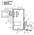
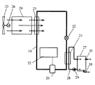
従来、この種の太陽熱利用装置としては、例えば、特開昭59−107150号公報、あるいは、実開昭61−7768号公報に記載されているような太陽熱利用装置があった。図12、図13は、前記公報に記載された従来の太陽熱を利用した太陽熱温水器を示すものである。
【0003】
図12において、1はヒートポンプ回路と熱交換して温水を貯める貯湯タンク、2は冷媒戻り管、3は圧縮機、4は貯湯タンク1の下部に配置した凝縮器、5は冷媒往管2aに設けた絞り、6は蒸発器で、集熱フィン7を有する、8は集熱熱交換器部で、閉構造とした集熱室9を有し、その太陽側をガラス板10で封止し、集熱室9内には蒸発器6と送風機11を配置し、ダンパー12、13で外気と開閉できる構成としている。
【0004】
また、図13において、集熱熱交換器部8は、外箱14の太陽光受光面にガラス板10、外箱内を表側と裏側に仕切るように配置した集熱板15、集熱板15の表面側の手前に開口した空気導入口16、空気導入口16に対し反対側の空気のリターン口17、空気導入口16近傍の外箱14の裏面に開口した排気口18、排気口18の内側に送風機11とヒートポンプ装置の蒸発器6を配設した構成としている。
【0005】
【発明が解決しようとする課題】
しかしながら、図12に示す従来の構成では、ヒートポンプの蒸発器6の全面で太陽熱を受ける構成であり、必要な集熱面積全体に蒸発器6を広げて配置する必要があるため、蒸発器6の面積が大きくなりヒートポンプの冷媒封入量が増大するばかりでなく、空気熱源のみの場合の必要風量が通常のヒートポンプの場合に比べ数倍になり、送風機11の駆動動力が増大するといった課題を有していた。
【0006】
また、図13に示す従来の構成では、集熱板15で太陽熱により空気を加熱して、その加熱昇温した空気をヒートポンプの蒸発器6に送る構成のため、蒸発器6は通常のヒートポンプの場合と同等の大きさで良いといった利点はあるが、日射量が多くなると必要以上に加熱能力が増大するといった課題を有していた。
【0007】
本発明は、前記従来の課題を解決するもので、太陽熱を受け取る蒸発器を小さくし、かつ効率の良い加熱運転のできる太陽熱利用装置を提供することを目的とする。
【0008】
【課題を解決するための手段】
本発明は上記課題を解決するために、太陽熱集熱器と、能力可変圧縮機を有したヒートポンプ回路と、前記太陽熱集熱器を通過した空気と熱交換する前記ヒートポンプ回路の蒸発器と、前記太陽熱集熱器の入口の空気温度を検知する集熱器入口空気温度センサーと、前記蒸発器の出口空気温度を検知する蒸発器出口空気温度センサーと、蒸発器出口空気温度を集熱器入口空気温度と略同一とするように前記能力可変圧縮機の能力設定を行う圧縮機能力可変制御手段とを備えた太陽熱利用装置としたものである。
【0009】
これによって、ヒートポンプ回路の蒸発器で直接日射を受ける必要がないために、蒸発器を通常のヒートポンプ回路のものと同等の大きさに小さくできる。また、蒸発器出口空気温度を集熱器入口空気温度と略同一とするように圧縮機の能力、つまり回転数設定を行うことにより、集熱器で受けた太陽熱の全量がヒートポンプ回路の蒸発器で熱交換され、蒸発器への供給空気の温度が高くなることで蒸発温度が高くなり、ヒートポンプの運転効率の良い加熱運転ができる。
【0010】
【発明の実施の形態】
請求項1に記載の発明は、太陽熱集熱器と、能力可変圧縮機を有したヒートポンプ回路と、前記太陽熱集熱器を通過した空気と熱交換する前記ヒートポンプ回路の蒸発器と、前記太陽熱集熱器の入口空気温度を検知する集熱器入口空気温度センサーと、蒸発器の出口空気温度を検知する蒸発器出口空気温度センサーと、蒸発器出口空気温度を集熱器入口空気温度と略同一とするように前記能力可変圧縮機の能力設定を行う圧縮機能力可変制御手段とを備えたものである。
【0011】
上記実施の形態において、ヒートポンプ回路の蒸発器で直接日射を受ける必要がないために、蒸発器を通常のヒートポンプ回路のものと同等の大きさに小さくできる。また、蒸発器出口空気温度を集熱器入口空気温度と略同一とするように圧縮機の回転数設定を行うことにより、集熱器で受けた太陽熱の全量がヒートポンプ回路の蒸発器で熱交換され、蒸発器への供給空気の温度が高くなることで蒸発温度が高くなり、ヒートポンプの運転効率の良い加熱運転ができる。
【0012】
請求項2に記載の発明は、請求項1の記載において、圧縮機能力可変制御手段を、圧縮機回転数設定値が最低回転数を下回る場合には、予め設定した圧縮機回転数に従って圧縮機を運転させる構成としたものである。
【0013】
上記実施の形態において、ヒートポンプ回路で受け取るべき太陽熱集熱器からの熱量が不足することを検知して、日射量が少ないか、または全くない場合でも、必要な加熱能力、効率の良い最適な状態における圧縮機の回転数を予め設定して運転させることができるため、ヒートポンプ回路の加熱能力を確保して、かつ効率の良い加熱運転ができる。
【0014】
請求項3に記載の発明は、請求項1の記載において、太陽熱量検知手段を備え、圧縮機能力可変制御手段は前記太陽熱量検知手段による太陽熱量が所定値を下回る場合には、予め設定した圧縮機回転数としたものである。
【0015】
上記実施の形態において、太陽熱量を検出して日射量が少ないか、または全くない場合でも、必要な加熱能力、効率の良い最適な状態における圧縮機の回転数を予め設定して運転させることができるため、ヒートポンプ回路の加熱能力を確保して、かつ効率の良い加熱運転ができる。
【0016】
請求項4に記載の発明は、請求項2または請求項3の記載において、圧縮機能力可変制御手段は予め設定した圧縮機回転数を、ヒートポンプの最大加熱負荷に見合った固定の圧縮機回転数とした構成とすることにより、日射量が少ないか、または全くない場合でも、必要な加熱能力を効率の良いヒートポンプ回路で確保できる。
【0017】
請求項5に記載の発明は、請求項2または請求項3の記載において、蒸発器の入口空気温度を検知する蒸発器入口空気温度センサーを備え、圧縮機能力可変制御手段は予め設定した圧縮機回転数を、前記蒸発器入口空気温度センサーの検知する蒸発器入口空気温度を基に設定される圧縮機回転数としたものである。
【0018】
上記実施の形態において、ヒートポンプの加熱能力と効率(COP)が蒸発器入口空気温度と圧縮機回転数で決まる特性を利用して、予め計測されたデーターに基づいて、蒸発器入口空気温度を基に、必要な加熱能力、効率の良い最適な状態における圧縮機の回転数を設定して運転させることができるため、日射量が少ないか、または全くない場合でも、ヒートポンプの加熱能力を確保してかつ、効率の良い加熱運転ができる。
【0019】
請求項6に記載の発明は、請求項2または請求項3の記載において、蒸発器の入口空気温度T3を検知する蒸発器入口空気温度センサーと、前記蒸発器の出口空気温度T2を検知する蒸発器出口空気温度センサーとを備え、圧縮機能力可変制御手段は予め設定した圧縮機回転数を、前記蒸発器入口空気温度センサーの検知する蒸発器入口空気温度T3と前記蒸発器出口空気温度センサーの検知する蒸発器出口空気温度T2との温度差T3−T2が予め設定した所定の温度差となる圧縮機回転数としたものである。
【0020】
上記実施の形態において、蒸発器の出入口空気温度差と風量で蒸発器の熱交換量、すなわち、ヒートポンプ回路の加熱能力が決まる特性を利用し、所定の蒸発器出入口空気温度差を必要な加熱量を得るための値に設定しておくことで、外気温度、日射量に関係なく、必要な加熱能力が得られる。また、少ない日射量でも、蒸発器入口空気温度が上昇することで所定の温度差とするために、圧縮機の回転数を落とすことになり、蒸発温度が上昇してヒートポンプの成績係数(効率)が高くなる。従って、日射量が少ないか、または全くない場合でも、ヒートポンプ回路の加熱能力を確保して、かつ効率の良い加熱運転ができる。
【0021】
請求項7に記載の発明は、請求項2または請求項3の記載において、蒸発器の入口空気温度を検知する蒸発器入口空気温度センサーと、蒸発器の入口冷媒温度を検知する蒸発器入口冷媒温度センサーとを備え、圧縮機能力可変制御手段は予め設定した圧縮機回転数を、前記蒸発器入口空気温度センサーの検知する蒸発器入口空気温度T3と前記蒸発器入口冷媒温度センサーの検知する蒸発器入口冷媒温度T4との温度差T3−T4が予め設定した所定の温度差となる圧縮機回転数としたものである。
【0022】
上記実施の形態において、蒸発器の入口空気温度と蒸発器入口冷媒温度との温度差で蒸発器の熱交換量、すなわち、ヒートポンプの加熱能力が決まる特性を利用し、前記予め設定した所定の温度差を必要な加熱量を得るための値に設定しておくことで、外気温度、日射量に関係なく、必要な加熱能力が得られる。
【0023】
また、少ない日射量でも、蒸発器入口空気温度が上昇することで、前記所定の温度差とするために、圧縮機の回転数を落とすことになり、蒸発器温度が上昇してヒートポンプ回路の成績係数(効率)が高くなる。従って、日射量が少ないか、または全くない場合でも、ヒートポンプ回路の加熱能力を確保して、かつ効率の良い加熱運転ができる。
【0024】
請求項8に記載の発明は、請求項3の記載において、太陽熱集熱器の集熱器出口空気温度T5を検知する集熱器出口空気温度センサーを設け、太陽熱量検知手段は集熱器入口空気温度T1と集熱器出口空気温度T5との集熱器出入口空気温度差を比較する集熱器出入口空気温度差比較手段を有する構成としたものである。
【0025】
上記実施の形態において、太陽熱量と直接関連する太陽熱集熱器の温度上昇値を利用することで、確実な制御ができる。また、集熱器入口空気温度センサーと集熱器出口空気温度センサーは他の制御機能と共用できるために、部品の共用化によるコストダウンの効果がある。
【0026】
請求項9に記載の発明は、請求項1〜請求項8のいずれか一項の記載において、太陽熱集熱器と前記蒸発器とを隣接して設けたもので、太陽熱集熱器から蒸発器までの通路における熱損失、通風抵抗が無くなり、熱交換効率の向上と送風機の動力低減による省エネルギー効果がある。
【0027】
請求項10に記載の発明は、請求項1〜請求項9のいずれか一項の記載において、蒸発器の空気入口に、外気を吸入する開閉可能な開閉手段と、前記開閉手段の開閉を制御する開閉制御手段とを設けたものである。
【0028】
上記実施の形態において、必要に応じて、太陽熱集熱器をバイパスし、通風抵抗を低減して送風手段の省電力化を実現する。従って、太陽熱集熱器の大面積化、あるいは太陽熱集熱器面を流れる空気流路を長くして太陽熱を多量に集熱する設計において、送風手段の小型化、省電力化を実現する。特に、日射量が少ない場合に蒸発器の通過風量を確保してヒ−トポンプ運転の効率向上を図れる。
【0029】
請求項11に記載の発明は、請求項1〜請求項10のいずれか一項の記載において、送風手段により起こる空気流が、送風手段のモータ、太陽熱集熱器、蒸発器の順に通過するように、前記送風手段と太陽熱集熱器と蒸発器を設置したものである。
【0030】
上記実施の形態において、送風手段の放熱を太陽熱集熱器から蒸発器へ送られる空気へ受熱させて蒸発器で熱交換させるので送風手段に必要な電力を冷媒の加熱に有効に利用する太陽熱利用装置とすることができる。
【0031】
【実施例】
以下、本発明の実施例について図面を参照しながら説明する。なお、以下の各実施例において、同じ構成および同じ作用効果を奏するものについては同一符号を付して詳細な説明を省略し、異なる部分を中心に説明する。
【0032】
(実施例1)
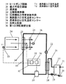
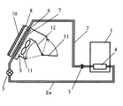
図1は本発明の実施例1における太陽熱利用装置を示す構成図である。図1において、19はヒートポンプ回路で、能力可変圧縮機20、凝縮器21、絞り22、蒸発器23により構成する。24は蒸発器23の風上側に配設した太陽熱集熱器、25は太陽熱集熱器24から蒸発器23へと空気を搬送する送風手段、26は送風手段25を駆動するモータ、27は貯水タンク、28は貯水タンク27の水を凝縮器21と熱交換するように循環させる水回路、29は水回路28に配設した循環ポンプ、30、31は貯水タンク27へ水を供給し、湯を搬出する供給搬出配管、32は能力可変圧縮機20の圧縮機回転数を可変制御するマイクロコンピュータ等で構成する圧縮機能力可変制御手段で、温度比較部35と、第1の回転数設定部36とを有する。33は集熱器入口空気温度T1を検知する集熱器入口空気温度センサー、34は蒸発器出口空気温度T2を検知する蒸発器出口空気温度センサーである。前記温度比較部35は、集熱器入口空気温度T1と蒸発器出口空気温度T2とを比較する。前記第1の回転数設定部36は集熱器入口空気温度T1と蒸発器出口空気温度T2とを温度比較部35で比較し、この比較に基いて蒸発器出口空気温度T2が集熱器入口空気温度T1と略同一となるように能力可変圧縮機20の回転数を設定するもので、温度比較部35と第1の回転数設定部36とで圧縮機能力可変制御手段32を構成するものである。
【0033】
以上のように構成された太陽熱利用装置について、以下その動作と作用を説明する。まず、送風手段25を作動させて外部から吸引した空気を、太陽熱集熱器24、蒸発器23の順に点線矢印のように通過させる。そして、通過の過程で太陽熱集熱器24で昇温された空気は、蒸発器23を通過する際に能力可変圧縮機20によりヒートポンプ回路19を循環する冷媒に熱を与える。
【0034】
そして、蒸発器23で熱を受けた冷媒は、能力可変圧縮機20で加圧昇温され、凝縮器21において冷媒を凝縮させることによって、貯水タンク27から循環ポンプ29で循環された循環水を加熱して、貯水タンク27に温水を蓄えることができる。この温水を供給搬出配管30、31より取り出して給湯、あるいは、暖房に使用することができる。
【0035】
このように装置が運転している際に圧縮機能力可変制御手段32の温度比較部35において、集熱器入口空気温度センサー33の検知した集熱器入口空気温度T1と蒸発器入口冷媒温度センサー35の検知した蒸発器入口冷媒温度T2とが比較され、蒸発器入出口空気温度T2が集熱器入口空気温度T1よりも低い場合には、第1の回転数設定部36で能力可変圧縮機20の回転数を小さい方向へ移行させる。
【0036】
また逆に、蒸発器出口空気温度T2が集熱器入口空気温度T1よりも高い場合には、第1の回転数設定部36で能力可変圧縮機20の回転数を大きい方向へ移行させる。このようにして、蒸発器出口空気温度T2を集熱器入口空気温度T1と略同一となるように能力可変圧縮機20の回転数を制御する。
【0037】
従って、蒸発器出口空気温度T2を集熱器入口空気温度T1と略同一にすることにより、太陽熱集熱器24で受けた太陽熱の全熱量がヒートポンプ回路19の蒸発器23で熱交換されることになり、また蒸発器23への供給空気の温度も高くなることで蒸発温度が高くなり、ヒートポンプ回路19の効率(COP)を飛躍的に大きくできる。
【0038】
以上のように本実施例の発明においては、太陽熱集熱器24と、能力可変圧縮機20を有したヒートポンプ回路19と、太陽熱集熱器24を通過した空気と熱交換するヒートポンプ回路19の蒸発器23と、圧縮機能力可変制御手段32を備えた構成とすることにより、ヒートポンプの蒸発器23で直接日射を受ける必要がないために、蒸発器23を通常のヒートポンプ回路のものと同等の大きさに小さくできる。
【0039】
また、圧縮機能力可変制御手段32に温度比較部35と第1の回転数設定部36を設け、蒸発器出口空気温度T2を集熱器入口空気温度T1と略同一になるように能力可変圧縮機20の回転数設定を行うことにより、太陽熱集熱器24で受けた太陽熱の全熱量がヒートポンプ回路19の蒸発器23で熱交換されることになり、また蒸発器23への供給空気の温度も高くなることで蒸発温度が高くなり、ヒートポンプ回路19の効率(COP)を飛躍的に大きくできる。
【0040】
(実施例2)
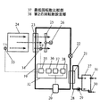
図2は本発明の実施例2における太陽熱利用装置を示す構成図である。この実施例の発明は、曇天日または雨天日で太陽の日射量が少ない、または無い場合でもヒートポンプ回路の加熱能力を確保するため、最低回転数比較部と第2の回転数設定部とを、図1に示す実施例1の圧縮機能力可変制御手段に加えた点で図1に示す実施例1の発明と異なり、それ以外は同じ内容である。
【0041】
図2において、圧縮機能力可変制御手段32は、温度比較部35、第1の回転数設定部36に加えて、更に能力可変圧縮機20の回転数と比較する基準値の最低回転数を記憶している最低回転数比較部37と、予め設定した圧縮機回転数、例えばヒートポンプ回路19の最大加熱負荷に見合った固定の圧縮機回転数を設定した第2の回転数設定部38とを備えている。
【0042】
以上のように構成された太陽熱利用装置において、その動作と作用は実施例1で説明したと同じように、能力可変圧縮機20によりヒートポンプ回路19を循環する冷媒が蒸発器23を通過する際に、太陽熱集熱器24で昇温された空気に加熱されて蒸発温度が高くなるとともに、圧縮機能力可変制御手段32の温度比較部35と第1の回転数設定部36により、蒸発器出口空気温度T2を集熱器入口空気温度T1と略同一になるように能力可変圧縮機20の回転数が設定されている。
【0043】
そして更に、第1の回転数設定部36で設定された圧縮機回転数設定値を最低回転数比較部37において最低回転数と比較し、前記最低回転数を下回る場合には、第2の回転数設定部38で予め設定した圧縮機回転数に従って能力可変圧縮機20を運転させるのである。
【0044】
すなわち、第1の回転数設定部36で設定された圧縮機回転数が最低回転数を下回るということは、太陽の日射量が少なくなり、太陽熱集熱器24での集熱量が少なくなり、ヒートポンプ回路19で受け取るべき太陽熱集熱器24からの熱量が不足していることを示しており、ヒートポンプ回路19の加熱能力が不足することになる。
【0045】
従って、必要な加熱能力が確保できるように圧縮機能力可変制御手段32により第2の回転数設定部38で予め設定した圧縮機回転数に切り替えて能力可変圧縮機20を運転させるものである。
【0046】
以上のように本実施例の発明は、ヒートポンプ回路19で受け取るべき太陽熱集熱器24からの熱量が不足することを検知して、曇天日または雨天日で日射量が少ないか、または全くない場合でも、必要な加熱能力、効率の良い最適な状態における能力可変圧縮機20の回転数を予め設定して運転させることができるため、ヒートポンプ回路19の加熱能力を確保してかつ、効率の良い加熱運転ができる。
【0047】
また、第2の回転数設定部38で予め設定した圧縮機回転数をヒートポンプの最大加熱負荷に見合った固定の圧縮機回転数に設定しているので、曇天日または雨天日で太陽の日射量が少ないか、または全く無い場合でも、確実に必要な加熱能力を効率の良いヒートポンプ回路で確保できる。
【0048】
(実施例3)
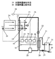
図3は本発明の実施例3における太陽熱利用装置を示す構成図である。本実施例の発明は、曇天日または雨天日で太陽の日射量が少ない、または無い場合でもヒートポンプ回路の加熱能力を確保するため、太陽熱量検知手段を設け、かつ太陽熱量比較手段を圧縮機能力可変制御手段に加えた点で図2に示す実施例2の発明と異なり、それ以外は同じ内容である。
【0049】
図3において、39は例えば日射計等の太陽熱量検知手段である。圧縮機能力可変制御手段32は、温度比較部35、第1の回転数設定部36、第2の回転数設定部38に加えて、更に前記太陽熱量検知手段39で検出された太陽熱量と比較する基準値である予め設定した所定値を記憶している太陽熱量比較手段40を備えている。
【0050】
以上のように構成された太陽熱利用装置において、その動作と作用は実施例1で説明したと同じように、能力可変圧縮機20によりヒートポンプ回路19を循環する冷媒が蒸発器23を通過する際に、太陽熱集熱器24で昇温された空気に加熱されて蒸発温度が高くなるとともに、圧縮機能力可変制御手段32の温度比較部35と第1の回転数設定部36により、蒸発器出口空気温度T2を集熱器入口空気温度T1と略同一になるように能力可変圧縮機20の回転数が設定されている。
【0051】
そして、太陽熱量検知手段39で検知された太陽熱量を、太陽熱量比較手段40において予め設定した所定値と比較し、検知された太陽熱量が前記所定値を下回る場合は、第2の回転数設定部38で予め設定した圧縮機回転数に従って能力可変圧縮機20を運転させる。すなわち、前記の太陽熱量が所定値を下回る場合には、太陽熱集熱器24での集熱量が少なくなり、ヒートポンプ回路19で受け取るべき太陽熱集熱器24からの熱量が不足していることを示しており、ヒートポンプの加熱能力が不足する。
【0052】
従って、必要な加熱能力が確保できるように圧縮機能力可変制御手段32により、予め設定した圧縮機回転数に切り替えて能力可変圧縮機20を運転させるものである。つまり、太陽熱量を検出して日射量が少ないか、または全くない場合でも、必要な加熱能力、効率の良い最適な状態における能力可変圧縮機20の回転数を予め設定して運転させることができるため、ヒートポンプ回路の加熱能力を確保してかつ、効率の良い加熱運転ができる。
【0053】
また、第2の回転数設定部38では、予め設定した圧縮機回転数をヒートポンプの最大加熱負荷に見合った固定の圧縮機回転数に設定しているので、曇天日または雨天日で日射量が少ないか、または全くない場合でも、確実に必要な加熱能力を効率の良いヒートポンプで確保できる。
【0054】
(実施例4)
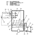
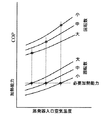
図4は本発明の実施例4における太陽熱利用装置を示す構成図で、図5は能力可変圧縮機を用いたヒートポンプの一般的な特性を説明する特性図である。本実施例の発明は、曇天日または雨天日で太陽の日射量が少ない、または無い場合でもヒートポンプ回路の加熱能力を確保するため、蒸発器入口空気温度センサーを設け、かつ圧縮機能力可変制御手段の第2の回転数設定部に回転数演算部の機能を持たせた点で図2に示す実施例2の発明と異なり、それ以外は同じ内容である。
【0055】
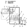
図4において、41は蒸発器23の蒸発器入口空気温度T3を検知するための蒸発器入口空気温度センサーである。圧縮機能力可変制御手段32は、温度比較部35、第1の回転数設定部36、最低回転数比較部37に加えて、更に前記蒸発器入口空気温度センサー41の検知する蒸発器入口空気温度T3を基に圧縮機回転数を演算するテーブル付きの回転数演算部42を有する第2の回転数設定部38aを備えている。すなわち、回転数演算部42は必要な加熱能力と効率の良い最適な状態における能力可変圧縮機20の回転数を演算するため、前記蒸発器入口空気温度センサー41の検知する蒸発器入口空気温度T3を基に図5に示すヒートポンプの一般特性に従い、蒸発器入口空気温度T3が低い時には能力可変圧縮機20の回転数を大きくし、蒸発器入口空気温度T3が高い時は能力可変圧縮機20の回転数を小さく設定するテーブルを備えている。
【0056】
以上のように構成された太陽熱利用装置において、その動作と作用は実施例1で説明したと同じように、能力可変圧縮機20によりヒートポンプ回路19を循環する冷媒が蒸発器23を通過する際に、太陽熱集熱器24で昇温された空気に加熱されて蒸発温度が高くなるとともに、圧縮機能力可変制御手段32の温度比較部35と第1の回転数設定部36により、蒸発器出口空気温度T2を集熱器入口空気温度T1と略同一になるように能力可変圧縮機20の回転数が設定されている。
【0057】
そして、ヒートポンプ回路19で受け取るべき太陽熱集熱器24からの熱量が不足すると、第1の回転数設定部36で設定された圧縮機回転数が最低回転数比較部37の最低回転数を下回り、第2の回転数設定部38aに移行する。
【0058】
圧縮機回転数設定が第2の回転数設定部38aに移行したら、第2の回転数設定部38aの回転数演算部42で、予め計測されたデーターに基づいて、蒸発器入口空気温度センサー41の検知した蒸発器入口空気温度T3を基に、圧縮機回転数を演算して能力可変圧縮機20を運転制御する。
【0059】
すなわち、回転数演算部42では、次のように演算する。ヒートポンプの一般特性として、図5に示すように、蒸発器入口空気温度T3が高くなると加熱能力、効率(COP)ともに大きくなり、また、圧縮機20の回転数が大きくなると、加熱能力は大きくなるが、効率は小さくなる特性を有している。例えば、必要加熱能力が一定であると設定した場合、図5に示すように、蒸発器入口空気温度T3が低い時には圧縮機20の回転数を大きくし、蒸発器入口空気温度T3が高い時は圧縮機20の回転数を小さく設定することにより、必要な加熱能力と効率の良い最適な状態における圧縮機20の回転数を設定して運転させることができる。
【0060】
以上のように、本実施例の発明においては、第2の回転数設定部38aの予め設定した圧縮機回転数を、蒸発器23の蒸発器入口空気温度を検知する蒸発器入口空気温度センサー41を備えて、前記蒸発器入口空気温度センサー41の検知する温度を基に設定される所定の回転数で圧縮機20を運転制御する構成としたものである。これにより、ヒートポンプ回路19の加熱能力と効率(COP)が蒸発器入口空気温度と圧縮機回転数で決まる特性を利用して、予め計測されたデーターに基づいて、蒸発器入口空気温度を基に、必要な加熱能力、効率の良い最適な状態における圧縮機20の回転数を設定して運転させることができるため、日射量が少ないか、または全くない場合でも、ヒートポンプの加熱能力を確保してかつ、効率の良い加熱運転ができる。
【0061】
(実施例5)
図6は本発明の実施例5における太陽熱利用装置を示す構成図である。本実施例の発明は、曇天日または雨天日で太陽の日射量が少ない、または無い場合でもヒートポンプ回路の加熱能力を確保するため、蒸発器入口空気温度センサーと蒸発器出口空気温度センサーとを設け、かつ圧縮機能力可変制御手段の第2の回転数設定部を、前記両センサーの検知した温度差と記憶している所定の温度差を比較する温度差比較部と、回転数設定部とで構成した点で図2に示す実施例2の発明と異なり、それ以外は同じ内容である。
【0062】
図6において、圧縮機能力可変制御手段32は、温度比較部35、第1の回転数設定部36に加えて、更に蒸発器入口空気温度センサー41の検知する蒸発器入口空気温度T3と蒸発器出口空気温度センサー34の検知する蒸発器出口空気温度T2との温度差T3−T2を、予め設定し記憶している所定の温度差と比較する温度差比較部43と、前記温度差T3−T2を所定の温度差となるように能力可変圧縮機20の回転数を制御する回転数設定部44とで構成した第2の回転数設定部38bを備えている。
【0063】
以上のように構成された太陽熱利用装置において、その動作と作用は実施例1で説明したと同じように、能力可変圧縮機20によりヒートポンプ回路19を循環する冷媒が蒸発器23を通過する際に、太陽熱集熱器24で昇温された空気に加熱されて蒸発温度が高くなるとともに、圧縮機能力可変制御手段32の温度比較部35と第1の回転数設定部36により、蒸発器出口空気温度T2を集熱器入口空気温度T1と略同一になるように能力可変圧縮機20の回転数が設定されている。
【0064】
そして、ヒートポンプ回路19で受け取るべき太陽熱集熱器24からの熱量が不足すると、圧縮機回転数設定が第2の回転数設定部38bに移行し、第2の回転数設定部38bの温度差比較部43において、蒸発器入口空気温度センサー41の検知する蒸発器入口空気温度T3と蒸発器出口空気温度センサー34の検知する蒸発器出口空気温度T2との温度差T3−T2を回転数設定部44が記憶している予め設定した所定の温度差と比較する。
【0065】
そして、前記回転数設定部44は温度差T3−T2が所定の温度差よりも大きい場合には、能力可変圧縮機20の回転数を小さい方向へ移行させ、また温度差T3−T2が所定の温度差よりも小さい場合には、能力可変圧縮機20の回転数を大きい方向へ移行させることで、前記温度差T3−T2を所定の温度差となるように能力可変圧縮機20の回転数を制御するのである。
【0066】
従って、ヒートポンプ回路19の風量が一定であり、蒸発器23の入口、出口の空気温度差T3―T2が一定であれば、蒸発器23での熱交換量が一定であり、すなわち、ヒートポンプ回路19の加熱能力も一定となるもので、例えば、必要加熱量に応じた蒸発器23の入口、出口の空気温度差を所定の温度差として予め設定しておけば、温度差T3−T2を所定の温度差となるように能力可変圧縮機20の回転数を制御することで、常に必要加熱量が得られる。
【0067】
なお、風量が変わる場合は、その風量に応じた温度差を所定の温度差として設定すればよい。
【0068】
以上のように本実施例の発明においては、予め設定した圧縮機回転数を、蒸発器23の蒸発器入口空気温度を検知する蒸発器入口空気温度センサー41と、蒸発器23の蒸発器出口空気温度を検知する蒸発器出口空気温度センサー34を備えて、蒸発器入口空気温度センサー41の検知する温度T3と蒸発器出口空気温度センサー34の検知する温度T2との温度差T3−T2が予め設定した所定の温度差となるごとく圧縮機回転数を制御する構成としたものである。
【0069】
これにより、蒸発器23の出入口空気温度差と風量で蒸発器の熱交換量、すなわち、ヒートポンプ回路の加熱能力が決まる特性を利用し、所定の蒸発器出入口空気温度差を必要な加熱量を得るための値に設定しておくことで、外気温度、日射量に関係なく、必要な加熱能力が得られる。
【0070】
従って、日射量が少ないか、または全くない場合でも、ヒートポンプの加熱能力を確保してかつ、効率の良い加熱運転ができる。
【0071】
(実施例6)
図7は本発明の実施例6における太陽熱利用装置を示す構成図である。本実施例の発明は、曇天日または雨天日で太陽の日射量が少ない、または無い場合でもヒートポンプ回路の加熱能力を確保するため、蒸発器入口空気温度と蒸発器入口冷媒温度との温度差を、記憶している所定の温度差と比較する温度差比較部と、この比較に基いて前記温度差が前記所定の温度差になるように圧縮機の回転数を設定する回転数設定部とで構成する第2の回転数設定部を、圧縮機能力可変制御手段を設けた点で図6に示す実施例5の発明と異なり、それ以外は同じ内容である。
【0072】
図7において、圧縮機能力可変制御手段32は、温度比較部35、第1の回転数設定部36に加えて、更に蒸発器入口空気温度センサー41の検知する蒸発器入口空気温度T3と蒸発器入口冷媒温度センサー45の検知する蒸発器入口冷媒温度T4との温度差T3−T4を、予め設定して記憶した所定の温度差と比較する温度差比較部46と、前記温度差T3−T4を所定の温度差となるように能力可変圧縮機20の回転数を制御する回転数設定部47とで構成した第2の回転数設定部38cを備えている。
【0073】
以上のように構成された太陽熱利用装置において、その動作と作用は実施例1で説明したと同じように、能力可変圧縮機20によりヒートポンプ回路19を循環する冷媒が蒸発器23を通過する際に、太陽熱集熱器24で昇温された空気に加熱されて蒸発温度が高くなるとともに、圧縮機能力可変制御手段32の温度比較部35と第1の回転数設定部36により、蒸発器出口空気温度T2を集熱器入口空気温度T1と略同一になるように能力可変圧縮機20の回転数が設定されている。
【0074】
そして、ヒートポンプ回路19で受け取るべき太陽熱集熱器24からの熱量が不足すると、圧縮機回転数設定が第2の回転数設定部38cに移行する。次に、第2の回転数設定部38cの温度差比較部46において、蒸発器入口空気温度センサー41の検知した蒸発器入口空気温度T3と蒸発器入口冷媒温度センサー45の検知した蒸発器入口冷媒温度T4との温度差T3−T4を、記憶している予め設定した所定の温度差と比較する。
【0075】
そして、回転数設定部47は前記温度差T3−T4が所定の温度差よりも大きい場合には、能力可変圧縮機20の回転数を小さい方向へ移行させ、前記温度差T3−T4が所定の温度差よりも小さい場合には、能力可変圧縮機20の回転数を大きい方向へ移行させることで、前記温度差T3−T4を所定の温度差となるように能力可変圧縮機20の回転数を制御する。
【0076】
従って、蒸発器23の外側の温度(蒸発器入口空気温度T3)と蒸発器23の内側の温度(蒸発器入口冷媒温度T4)との温度差が一定であれば、蒸発器23での熱交換量が一定であり、すなわち、ヒートポンプ回路19の加熱能力も一定となるもので、例えば、必要加熱量に応じた蒸発器入口空気温度T3と蒸発器入口冷媒温度T4との温度差を所定の温度差として予め設定しておけば、温度差T3−T4を所定の温度差となるように能力可変圧縮機20の回転数を制御することで常に必要加熱量が得られる。
【0077】
以上のように、本実施例の発明においては、予め設定した圧縮機回転数を、蒸発器23の蒸発器入口空気温度T3を検知する蒸発器入口空気温度センサー41と、蒸発器23の蒸発器入口冷媒温度T4を検知する蒸発器入口冷媒温度センサー45とを備えて、蒸発器入口空気温度センサー41の検知した温度T3と蒸発器入口冷媒温度センサー45の検知した温度T4との温度差T3−T4が予め設定した所定の温度差となるように能力可変圧縮機20の回転数を回転数設定部47で制御する構成としたものである。
【0078】
これにより、蒸発器23の蒸発器入口空気温度T3と蒸発器23の蒸発器入口冷媒温度T4との温度差T3−T4で蒸発器23の熱交換量、すなわち、ヒートポンプ回路19の加熱能力が決まる特性を利用し、前記予め設定した所定の温度差を必要な加熱量を得るための値に設定しておくことで、外気温度、日射量に関係なく、必要な加熱能力が得られる。
【0079】
従って、曇天日または雨天日で日射量が少ないか、または全くない場合でも、ヒートポンプの加熱能力を確保してかつ、効率の良い加熱運転ができる。
【0080】
(実施例7)
図8は本発明の実施例7における太陽熱利用装置を示す構成図である。本実施例の発明は、集熱器出口空気温度センサーを設け、かつ図3に示す実施例3の太陽日射量を直接に検出する太陽熱量検出手段を、集熱器入口空気温度センサーの検出する温度と集熱器出口空気温度センサーの検出する温度とを比較する集熱器出入口空気温度差比較手段で兼ねた点が実施例3の発明と異なり、それ以外の内容は同じである。
【0081】
図8において、48は太陽熱集熱器24の出口の空気温度T5を検知する集熱器出口空気温度センサーである。太陽熱量検知手段39aは、集熱器入口空気温度センサー33の検知する集熱器入口空気温度T1と、集熱器出口空気温度センサー48の検知する集熱器出口空気温度T5との集熱器出入口温度差を比較する集熱器出入口空気温度差比較手段49で構成する。
【0082】
以上のように構成された太陽熱利用装置において、その動作と作用は実施例3で説明したと同じように、能力可変圧縮機20によりヒートポンプ回路19を循環する冷媒が蒸発器23を通過する際に、太陽熱集熱器24で昇温された空気に加熱されて蒸発温度が高くなるとともに、圧縮機能力可変制御手段32の温度比較部35と第1の回転数設定部36により、蒸発器出口空気温度T2を集熱器入口空気温度T1と略同一になるように能力可変圧縮機20の回転数が設定されている。
【0083】
そして、太陽熱量検知手段39aで検知された太陽熱量を、すなわち集熱器入口空気温度センサー33の検知した集熱器入口空気温度T1と、集熱器出口空気温度センサー48の検知した集熱器出口空気温度T5とを集熱器出入口温度差比較手段49で比較した集熱器出入口温度差を、太陽熱量比較手段40において予め設定した所定値と比較し、検知された太陽熱量(集熱器出入口温度差)が前記所定値を下回る場合は、第2の回転数設定部38で予め設定した圧縮機回転数に従って能力可変圧縮機20を運転させる。すなわち、前記太陽熱量が所定値を下回る場合には、太陽熱集熱器24での集熱量が少なくなり、ヒートポンプ回路19で受け取るべき太陽熱集熱器24からの熱量が不足していることを示しており、ヒートポンプの加熱能力が不足する。
【0084】
従って、必要な加熱能力が確保できるように圧縮機能力可変制御手段32により、予め設定した圧縮機回転数に切り替えて能力可変圧縮機20を運転させるものである。
【0085】
一般に太陽日射量を受けて集熱器出入口空気温度差が生じるもので、日射量、すなわち、太陽熱量と集熱器出入口空気温度差は相関性がある。実際は太陽熱集熱器24に熱容量があるために、集熱器出入口空気温度差の変化は日射量変化に対してかなり遅れて変化する。この特性は、時定数が大きなヒートポンプサイクルの圧縮機回転数の急激な変化を避けるのに適している。
【0086】
以上のように、本実施例の発明においては、太陽熱量検知手段39aを、太陽熱集熱器24の入口の空気温度を検知する集熱器入口空気温度センサー33と、太陽熱集熱器24の出口の空気温度を検知する集熱器出口空気温度センサー48と、集熱器出入口空気温度差を比較する集熱器出入口空気温度差比較手段49とで構成したので、太陽熱量と直接関連する太陽熱集熱器24の温度上昇値を利用することで、確実な制御ができる。また、集熱器入口空気温度センサー33、集熱器出口空気温度センサー48は他の制御機能と共用できるために、部品の共用化によるコストダウンの効果がある。
【0087】
(実施例8)
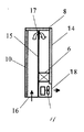
図9は本発明の実施例8における太陽熱利用装置を示す構成図である。本実施例の発明は、蒸発器の熱交換効率等の向上を図るため、ヒートポンプ回路の蒸発器と太陽熱集熱器を隣接して配設した点が、図1〜図8に示す実施例1〜実施例7の各発明と異なり、それ以外の内容は同じである。
【0088】
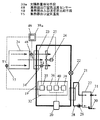
図9において、太陽熱集熱器24とヒートポンプ回路19の蒸発器23は隣接して設置した構成としている。図中、53は点線で示すガイド筒で、太陽熱集熱器24から蒸発器23への空気の流れを案内するものである。
【0089】
以上のように構成された太陽熱利用装置において、その動作と作用は実施例1で説明したと同じように、能力可変圧縮機20によりヒートポンプ回路19を循環する冷媒が蒸発器23を通過する際に、ガイド筒53に案内されて流れ太陽熱集熱器24で昇温された空気に加熱され蒸発温度が高くなるとともに、圧縮機能力可変制御手段32により、蒸発器出口空気温度T2を集熱器入口空気温度T1と略同一になるように能力可変圧縮機20の回転数を制御している。
【0090】
そして、太陽熱集熱器24と蒸発器23は隣接することで、太陽熱集熱器24と蒸発器23の間の距離が短くなり、接続部(前記距離)での熱損失、通風抵抗が無くなる。
【0091】
以上のように本実施例の発明においては、太陽熱集熱器24と蒸発器を隣接して設置した構成としたことにより、太陽熱集熱器24から蒸発器23までの間における熱損失、通風抵抗が軽減され、熱交換効率の向上と送風手段25の動力低減による省エネルギー効果が生じる。
【0092】
また、太陽熱集熱器24と蒸発器23を例えば一体に構成すると、装置の小型軽量化を図ることができるばかりでなく、空気を蒸発器23へ導く通路が不要となるため、装置の低コスト化と施工性を向上させることができる。
【0093】
(実施例9)
図10は本発明の実施例9における太陽熱利用装置を示す構成図である。本実施例の発明は、ヒートポンプ回路の運転効率等を高めるため、蒸発器と太陽熱集熱器の間の通路に、日射量に応じて外気導入を制御する開閉手段を設けた点が、図1〜図9に示す実施例1〜実施例8の各発明と異なり、それ以外の内容は同じである。
【0094】
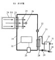
図10において、50は蒸発器23の空気入口の近傍におけるガイド筒53に設けたバイパス吸込部、51はバイパス吸込部50の開閉を行う開閉手段、52は開閉手段51の開閉を制御する開閉制御手段で、太陽日射量が多い場合には開閉手段51を開放から閉鎖へ切換え、太陽日射量が少ない曇天日、あるいは雨天日の場合には開閉手段51を閉鎖から開放へ切換える制御を行うものである。
【0095】
以上のように構成された太陽熱利用装置において、その動作と作用は実施例1で説明したと同じように、能力可変圧縮機20によりヒートポンプ回路19を循環する冷媒が蒸発器23を通過する際に、ガイド筒53に案内されて流れ太陽熱集熱器24で昇温された空気に加熱され蒸発温度が高くなるとともに、圧縮機能力可変制御手段32により、蒸発器出口空気温度T2を集熱器入口空気温度T1と略同一になるように能力可変圧縮機20の回転数を制御している。
【0096】
そして、最初に太陽日射量が多い場合には開閉制御手段52が開閉手段51を開放から閉鎖へ切換えて、開閉手段51がバイパス吸込部50を閉鎖する。そのため、外気は唯一、太陽熱集熱器24へ流入し、この外気の空気は外気温より大幅な高温空気に加熱されて蒸発器23へ流れ、蒸発器23を流れるヒ−トポンプ回路19の冷媒を蒸発ガス化させる。
【0097】
次に、太陽日射量が少ない曇天日、あるいは雨天日の場合には開閉制御手段52が開閉手段51を閉鎖から開放へ切換えて、開閉手段51がバイパス吸込部50を開放し、送風手段25の吸引力によって、バイパス吸込部50から多量の外気が蒸発器23の入口へ吸引される。そして、太陽熱集熱器24から流入してきた空気と合流して蒸発器23へ流れる。
【0098】
この場合、太陽日射量が少ないため、太陽熱集熱器24を通過する空気の温度上昇は少なく、合流して蒸発器23の入口へ流入する空気の温度は外気温度と殆ど同じである。そして、蒸発器23の空気入口近傍のバイパス吸込部50から外気を導入するため、通風抵抗が少なく、蒸発器23の通過風量が増加してヒ−トポンプ回路19の運転効率が高くなる。
【0099】
従って、太陽日射量が多い場合には、高温空気をそのまま小風量で蒸発器23に流して高効率化を図り、太陽日射量が少ない曇天日、あるいは雨天日の場合には、集熱ユニットの外郭をなすガイド筒53のバイパス吸込部50から大風量を蒸発器23へ流して高効率化を図ることができる。また、太陽日射量が多い場合にバイパス吸込部50を閉鎖するため、外気風速が大きい時にバイパス吸込部50から自然風が集熱ユニット内へ流入することがないため、太陽熱で温めた高温空気の温度低下を防止できる。
【0100】
以上のように本実施例の発明においては、蒸発器23の空気入口に、外気を吸入するための開閉が可能な開閉手段51と、開閉手段51の開閉を制御する開閉制御手段52を備えた構成とすることにより、必要に応じて太陽熱集熱器24をバイパスし、通風抵抗を低減して送風手段25の省電力化を実現する。従って、太陽熱集熱器24の大面積化、あるいは太陽熱集熱器24面を流れる空気流路を長くして太陽熱を多量に集熱する設計において、送風手段25の小型化、省電力化を実現できる。特に、日射量が少ない場合に蒸発器23の通過風量を確保してヒ−トポンプ運転の効率向上を図れる。
【0101】
(実施例10)
図11は本発明の実施例10における太陽熱利用装置を示す構成図である。本実施例の発明は、ヒートポンプ回路の運転効率等を高めるため、送風手段による空気流を、送風手段、太陽熱集熱器、蒸発器の順に流して送風手段のモータの熱を蒸発器の加熱に活用すようにした点が、図1〜図10に示す実施例1〜実施例9の各発明と異なり、それ以外の内容は同じである。
【0102】
図11において、送風手段25のファンにより生じる空気流が、送風手段25のファンを駆動するモータ26、太陽熱集熱器24、蒸発器23の順に空気が流れるように、前記送風手段25、太陽熱集熱器24、蒸発器23を配設した構成としている。
【0103】
以上のように構成された太陽熱利用装置において、その動作と作用は実施例1で説明したと同じように、能力可変圧縮機20によりヒートポンプ回路19を循環する冷媒が蒸発器23を通過する際に、太陽熱集熱器24で昇温された空気に加熱され蒸発温度が高くなるとともに、圧縮機能力可変制御手段32により、蒸発器出口空気温度T2を集熱器入口空気温度T1と略同一になるように能力可変圧縮機20の回転数が制御される。
【0104】
そして、送風手段25を駆動するモータ26は電力を消費するため、モータ自身が発熱し高温となる。しかし、モータ26は送風手段25によって送風される空気に曝されているので、モータ26が消費した電力は熱となって空気へ伝熱される。モータ26の熱を受熱した空気は、太陽集熱器24で加熱され一段と温度上昇し蒸発器23で冷媒と熱交換するので、本実施例の構成により、モータ26で消費した電力を冷媒の加熱に利用することができる。
【0105】
以上のように本実施例の発明においては、空気が送風手段25、太陽熱集熱器24、蒸発器23の順に通過するように設置した構成とすることにより、送風手段26の放熱を太陽熱集熱器24から蒸発器23へ送られる空気へ受熱させて蒸発器23で熱交換させるので送風手段25に必要な電力を冷媒の加熱に有効に利用して運転効率の高い装置とすることができる。
【0106】
【発明の効果】
以上の説明から明らかなように請求項1〜請求項11に記載の発明によれば、日射量、外気温度に影響されずに必要な加熱能力を確保してかつ、効率の良い加熱運転ができる。
【図面の簡単な説明】
【図1】本発明の実施例1における太陽熱利用装置を示す構成図
【図2】同実施例2における太陽熱利用装置を示す構成図
【図3】同実施例3における太陽熱利用装置示す構成図
【図4】同実施例4における太陽熱利用装置を示す構成図
【図5】ヒートポンプ回路の一般的な特性を説明する特性図
【図6】本発明の実施例5における太陽熱利用装置を示す構成図
【図7】同実施例6における太陽熱利用装置を示す構成図
【図8】同実施例7における太陽熱利用装置を示す構成図
【図9】同実施例8における太陽熱利用装置を示す構成図
【図10】同実施例9における太陽熱利用装置を示す構成図
【図11】同実施例10における太陽熱利用装置を示す構成図
【図12】従来の太陽熱利用装置を示す構成図
【図13】従来の太陽熱利用装置を示す構成図
【符号の説明】
19 ヒートポンプ回路
20 能力可変圧縮機
23 蒸発器
24 太陽熱集熱器
25 送風手段
32 圧縮機能力可変制御手段
33 集熱器入口空気温度センサー
34 蒸発器出口空気温度センサー
35 温度比較部
36 第1の回転数設定部
37 最低回転数比較部
38、38a、38b、38c 第2の回転数設定部
39、39a 太陽熱量検知手段
40 太陽熱量比較手段
41 蒸発器入口空気温度センサー
42 回転数演算部
43、46 温度差比較部
45 蒸発器入口冷媒温度センサー
44、47 回転数設定部
48 集熱器出口空気温度センサー
49 集熱器出入口空気温度差比較手段
51 開閉手段
52 開閉制御手段[0001]
BACKGROUND OF THE INVENTION
The present invention relates to a solar heat utilization apparatus that performs hot water supply or heating by a heat pump that operates by using solar heat as a heat source in fine weather days and outside air heat as a heat source in bad weather.
[0002]
[Prior art]
Conventionally, as this type of solar heat utilization apparatus, there has been a solar heat utilization apparatus described in, for example, Japanese Patent Application Laid-Open No. 59-107150 or Japanese Utility Model Laid-Open No. 61-7768. 12 and 13 show a solar water heater using the conventional solar heat described in the publication.
[0003]
In FIG. 12, 1 is a hot water storage tank for storing hot water by exchanging heat with the heat pump circuit, 2 is a refrigerant return pipe, 3 is a compressor, 4 is a condenser arranged at the lower part of the hot water storage tank 1, and 5 is a refrigerant
[0004]
In FIG. 13, the heat collection
[0005]
[Problems to be solved by the invention]
However, in the conventional configuration shown in FIG. 12, the solar heat is received on the entire surface of the
[0006]
In the conventional configuration shown in FIG. 13, the
[0007]
This invention solves the said conventional subject, and it aims at providing the solar-heat utilization apparatus which can make the evaporator which receives solar heat small, and can perform efficient heating operation.
[0008]
[Means for Solving the Problems]
In order to solve the above-mentioned problems, the present invention provides a solar heat collector, a heat pump circuit having a variable capacity compressor, an evaporator of the heat pump circuit that exchanges heat with air that has passed through the solar heat collector, A collector inlet air temperature sensor for detecting the air temperature at the inlet of the solar collector, an evaporator outlet air temperature sensor for detecting the outlet air temperature of the evaporator, and the evaporator outlet air temperature as the collector inlet air The solar heat utilization apparatus includes a compression function force variable control means for setting the capacity of the variable capacity compressor so as to be substantially the same as the temperature.
[0009]
Thereby, since it is not necessary to receive direct sunlight in the evaporator of the heat pump circuit, the evaporator can be reduced to the same size as that of a normal heat pump circuit. In addition, by setting the compressor capacity, that is, the rotation speed so that the evaporator outlet air temperature is substantially the same as the collector inlet air temperature, the total amount of solar heat received by the collector can be changed to the evaporator of the heat pump circuit. The heat exchange is performed at the evaporating temperature, and the temperature of the air supplied to the evaporator is increased, whereby the evaporating temperature is increased.
[0010]
DETAILED DESCRIPTION OF THE INVENTION
The invention according to claim 1 is a solar heat collector, a heat pump circuit having a variable capacity compressor, an evaporator of the heat pump circuit that exchanges heat with air that has passed through the solar heat collector, and the solar heat collector. The collector inlet air temperature sensor that detects the inlet air temperature of the heater, the evaporator outlet air temperature sensor that detects the outlet air temperature of the evaporator, and the evaporator outlet air temperature is substantially the same as the collector inlet air temperature And a compression function force variable control means for setting the capacity of the variable capacity compressor.
[0011]
In the above embodiment, the evaporator of the heat pump circuit does not need to be directly exposed to sunlight, so that the evaporator can be reduced to the same size as that of a normal heat pump circuit. In addition, by setting the rotation speed of the compressor so that the evaporator outlet air temperature is approximately the same as the collector inlet air temperature, the total amount of solar heat received by the collector is heat exchanged by the evaporator of the heat pump circuit. In addition, since the temperature of the supply air to the evaporator is increased, the evaporation temperature is increased, and a heating operation with good operation efficiency of the heat pump can be performed.
[0012]
According to a second aspect of the present invention, in the first aspect, when the compressor rotational speed setting value is lower than the minimum rotational speed, the compressor functional force variable control means is configured to perform the compressor according to the preset compressor rotational speed. Is configured to operate.
[0013]
In the above embodiment, it is detected that the amount of heat from the solar heat collector to be received by the heat pump circuit is insufficient, and even when the amount of solar radiation is small or not at all, necessary heating capacity, optimal state with good efficiency Since the compressor can be operated with the number of revolutions set in advance, the heating capacity of the heat pump circuit can be ensured and an efficient heating operation can be performed.
[0014]
The invention according to
[0015]
In the above embodiment, even if the solar heat amount is detected and the amount of solar radiation is small or not at all, it is possible to operate by setting the number of revolutions of the compressor in an optimal state with necessary heating capacity and efficiency. Therefore, the heating capability of the heat pump circuit is ensured and an efficient heating operation can be performed.
[0016]
According to a fourth aspect of the present invention, in the second or third aspect of the present invention, the variable compression function force control means uses a preset compressor rotational speed corresponding to the maximum heating load of the heat pump. With this configuration, even when the amount of solar radiation is small or not at all, the necessary heating capacity can be ensured by an efficient heat pump circuit.
[0017]
According to a fifth aspect of the present invention, there is provided the evaporator according to the second or third aspect, further comprising an evaporator inlet air temperature sensor for detecting an inlet air temperature of the evaporator, wherein the compression function force variable control means is a preset compressor. The rotation speed is the compressor rotation speed set based on the evaporator inlet air temperature detected by the evaporator inlet air temperature sensor.
[0018]
In the above embodiment, the heat inlet capacity and efficiency (COP) of the heat pump are determined based on the evaporator inlet air temperature based on the data measured in advance using the characteristics determined by the evaporator inlet air temperature and the compressor rotational speed. In addition, the compressor can be operated by setting the necessary heating capacity and the number of revolutions of the compressor in an optimal and efficient state, so that the heating capacity of the heat pump can be ensured even when there is little or no solar radiation. In addition, an efficient heating operation can be performed.
[0019]
According to a sixth aspect of the present invention, in the second or third aspect of the present invention, an evaporator inlet air temperature sensor that detects the inlet air temperature T3 of the evaporator and an evaporation that detects the outlet air temperature T2 of the evaporator. The compressor outlet air temperature sensor includes a compressor function variable control means, and the compressor inlet air temperature T3 detected by the evaporator inlet air temperature sensor and the evaporator outlet air temperature sensor. The temperature difference T3-T2 with respect to the detected evaporator outlet air temperature T2 is the compressor rotation speed at which a predetermined temperature difference is set in advance.
[0020]
In the above embodiment, the heat exchange amount of the evaporator is determined by the difference in the inlet / outlet air temperature of the evaporator and the air volume, that is, the heating capacity of the heat pump circuit is used, and the predetermined evaporator inlet / outlet air temperature difference is used as the required heating amount. By setting the value to obtain the required heat capacity, the necessary heating capacity can be obtained regardless of the outside air temperature and the amount of solar radiation. In addition, even if the amount of solar radiation is small, the temperature at the inlet of the evaporator rises, resulting in a predetermined temperature difference. Therefore, the number of revolutions of the compressor will be reduced, and the evaporation temperature will rise and the coefficient of performance (efficiency) of the heat pump. Becomes higher. Therefore, even when there is little or no solar radiation, the heating capability of the heat pump circuit is ensured and an efficient heating operation can be performed.
[0021]
According to a seventh aspect of the invention, in the second or third aspect of the invention, an evaporator inlet air temperature sensor for detecting an evaporator inlet air temperature, and an evaporator inlet refrigerant for detecting an evaporator inlet refrigerant temperature. A temperature sensor, and the variable compression function force control means is configured to evaporate a preset compressor speed detected by the evaporator inlet air temperature sensor T3 detected by the evaporator inlet air temperature sensor and the evaporator inlet refrigerant temperature sensor. The compressor rotational speed is such that the temperature difference T3-T4 from the inlet refrigerant temperature T4 is a predetermined temperature difference.
[0022]
In the above-described embodiment, the predetermined temperature is set in advance using the characteristic that the heat exchange amount of the evaporator, that is, the heating capacity of the heat pump, is determined by the temperature difference between the evaporator inlet air temperature and the evaporator inlet refrigerant temperature. By setting the difference to a value for obtaining the necessary amount of heating, the necessary heating capacity can be obtained regardless of the outside air temperature and the amount of solar radiation.
[0023]
In addition, even when the amount of solar radiation is small, the evaporator inlet air temperature rises, so that the predetermined temperature difference is reached, so that the number of revolutions of the compressor is reduced, the evaporator temperature rises, and the performance of the heat pump circuit. The coefficient (efficiency) increases. Therefore, even when there is little or no solar radiation, the heating capability of the heat pump circuit is ensured and an efficient heating operation can be performed.
[0024]
According to an eighth aspect of the present invention, in the third aspect, a collector outlet air temperature sensor for detecting a collector outlet air temperature T5 of the solar collector is provided, and the solar heat amount detecting means is a collector inlet. A heat collector inlet / outlet air temperature difference comparing means for comparing the temperature difference of the collector inlet / outlet air between the air temperature T1 and the collector outlet air temperature T5 is provided.
[0025]
In the said embodiment, reliable control can be performed by utilizing the temperature rise value of the solar heat collector which is directly related to the amount of solar heat. Further, since the collector air temperature sensor and the collector outlet air temperature sensor can be shared with other control functions, there is an effect of cost reduction by sharing parts.
[0026]
A ninth aspect of the present invention provides the solar collector according to any one of the first to eighth aspects, wherein the solar heat collector and the evaporator are provided adjacent to each other. There is no heat loss and ventilation resistance in the passage to the end, and there is an energy saving effect by improving the heat exchange efficiency and reducing the power of the blower.
[0027]
A tenth aspect of the present invention provides the control device according to any one of the first to ninth aspects, wherein the opening / closing means for sucking outside air to the air inlet of the evaporator and the opening / closing of the opening / closing means are controlled. Open / close control means is provided.
[0028]
In the above embodiment, if necessary, the solar heat collector is bypassed to reduce the ventilation resistance, thereby realizing power saving of the blowing means. Therefore, in the design of collecting a large amount of solar heat by increasing the area of the solar heat collector or by extending the air flow path flowing through the surface of the solar heat collector, it is possible to reduce the size of the blower and save power. In particular, when the amount of solar radiation is small, the amount of air passing through the evaporator can be secured to improve the efficiency of the heat pump operation.
[0029]
The invention described in
[0030]
In the above-described embodiment, since the heat dissipated from the air blowing means is received by the air sent from the solar heat collector to the evaporator and heat exchange is performed by the evaporator, the solar heat utilization that effectively uses the electric power necessary for the air blowing means for heating the refrigerant It can be a device.
[0031]
【Example】
Embodiments of the present invention will be described below with reference to the drawings. In the following embodiments, the same components and the same operational effects are denoted by the same reference numerals, detailed description thereof is omitted, and different portions will be mainly described.
[0032]
Example 1
FIG. 1 is a configuration diagram showing a solar heat utilization apparatus in Embodiment 1 of the present invention. In FIG. 1,
[0033]
About the solar heat utilization apparatus comprised as mentioned above, the operation | movement and an effect | action are demonstrated below. First, the air sucked from the outside by operating the air blowing means 25 is passed in the order of the
[0034]
Then, the refrigerant that has received heat in the
[0035]
Thus, when the apparatus is operating, in the
[0036]
Conversely, when the evaporator outlet air temperature T2 is higher than the collector inlet air temperature T1, the first rotational
[0037]
Therefore, by making the evaporator outlet air temperature T2 substantially the same as the collector inlet air temperature T1, the total amount of solar heat received by the
[0038]
As described above, in the present embodiment, the evaporation of the
[0039]
Also, the compression function force variable control means 32 is provided with a
[0040]
(Example 2)
FIG. 2 is a block diagram showing a solar heat utilization apparatus in
[0041]
In FIG. 2, in addition to the
[0042]
In the solar heat utilization apparatus configured as described above, the operation and action thereof are the same as described in the first embodiment, when the refrigerant circulating through the
[0043]
Further, the compressor rotational speed setting value set by the first rotational
[0044]
That is, if the compressor rotational speed set by the first rotational
[0045]
Therefore, the
[0046]
As described above, the invention of this embodiment detects that the amount of heat from the
[0047]
Moreover, since the compressor rotation speed set in advance by the second rotation
[0048]
(Example 3)
FIG. 3 is a block diagram showing a solar heat utilization apparatus in
[0049]
In FIG. 3, 39 is solar calorie | heat amount detection means, such as a solar radiation meter. In addition to the
[0050]
In the solar heat utilization apparatus configured as described above, the operation and action thereof are the same as described in the first embodiment, when the refrigerant circulating through the
[0051]
Then, the amount of solar heat detected by the solar heat amount detection means 39 is compared with a predetermined value set in advance in the solar heat amount comparison means 40. If the detected amount of solar heat is less than the predetermined value, the second rotational speed setting is performed. The
[0052]
Therefore, the
[0053]
In the second rotation
[0054]
Example 4
FIG. 4 is a block diagram showing a solar heat utilization apparatus in
[0055]
In FIG. 4,
[0056]
In the solar heat utilization apparatus configured as described above, the operation and action thereof are the same as described in the first embodiment, when the refrigerant circulating through the
[0057]
And when the amount of heat from the
[0058]
When the compressor rotational speed setting shifts to the second rotational speed setting unit 38a, the evaporator inlet
[0059]
That is, the rotation
[0060]
As described above, in the invention of the present embodiment, the compressor inlet
[0061]
(Example 5)
FIG. 6 is a block diagram showing a solar heat utilization apparatus in Embodiment 5 of the present invention. The invention of the present embodiment is provided with an evaporator inlet air temperature sensor and an evaporator outlet air temperature sensor in order to ensure the heating capacity of the heat pump circuit even when the amount of solar radiation is small or absent on a cloudy or rainy day. In addition, the second rotation speed setting unit of the variable compression function force control means includes a temperature difference comparison unit that compares a temperature difference detected by the two sensors and a stored predetermined temperature difference, and a rotation speed setting unit. In the point which comprised, it differs from invention of Example 2 shown in FIG. 2, and other than that is the same content.
[0062]
In FIG. 6, in addition to the
[0063]
In the solar heat utilization apparatus configured as described above, the operation and action thereof are the same as described in the first embodiment, when the refrigerant circulating through the
[0064]
When the amount of heat from the
[0065]
When the temperature difference T3-T2 is larger than the predetermined temperature difference, the rotational
[0066]
Accordingly, if the air volume of the
[0067]
If the air volume changes, a temperature difference corresponding to the air volume may be set as a predetermined temperature difference.
[0068]
As described above, in the invention of the present embodiment, the preset compressor rotation speed is determined based on the evaporator inlet
[0069]
Thus, the heat exchange amount of the evaporator, that is, the heating capacity of the heat pump circuit is determined by the difference in the inlet / outlet air temperature of the
[0070]
Therefore, even when there is little or no solar radiation, the heating capability of the heat pump can be ensured and an efficient heating operation can be performed.
[0071]
(Example 6)
FIG. 7 is a block diagram showing a solar heat utilization apparatus in
[0072]
In FIG. 7, in addition to the
[0073]
In the solar heat utilization apparatus configured as described above, the operation and action thereof are the same as described in the first embodiment, when the refrigerant circulating through the
[0074]
When the amount of heat from the
[0075]
Then, when the temperature difference T3-T4 is larger than the predetermined temperature difference, the rotation speed setting unit 47 shifts the rotation speed of the
[0076]
Therefore, if the temperature difference between the temperature outside the evaporator 23 (evaporator inlet air temperature T3) and the temperature inside the evaporator 23 (evaporator inlet refrigerant temperature T4) is constant, heat exchange in the
[0077]
As described above, in the invention of the present embodiment, the preset compressor rotation speed is determined based on the evaporator inlet
[0078]
Thereby, the heat exchange amount of the
[0079]
Therefore, even when there is little or no solar radiation on a cloudy day or a rainy day, the heating capability of the heat pump can be ensured and an efficient heating operation can be performed.
[0080]
(Example 7)
FIG. 8 is a block diagram showing a solar heat utilization apparatus in Embodiment 7 of the present invention. In the invention of this embodiment, the solar collector amount detecting means for directly detecting the solar solar radiation amount of the third embodiment shown in FIG. 3 provided with the collector outlet air temperature sensor is detected by the collector inlet air temperature sensor. Unlike the invention of the third embodiment, the contents other than the above are the same except that the temperature collector and the inlet / outlet air temperature difference comparison means for comparing the temperature detected by the outlet air temperature sensor are used.
[0081]
In FIG. 8,
[0082]
In the solar heat utilization apparatus configured as described above, the operation and action thereof are the same as described in the third embodiment, when the refrigerant circulating in the
[0083]
And the amount of solar heat detected by the solar heat amount detecting means 39a, that is, the heat collector inlet air temperature T1 detected by the heat collector inlet
[0084]
Therefore, the
[0085]
Generally, a solar collector air temperature difference is generated upon receiving solar solar radiation, and the solar radiation amount, that is, the solar heat amount and the collector air inlet / outlet air temperature difference is correlated. Actually, since the
[0086]
As described above, in the invention of the present embodiment, the solar heat amount detection means 39a is configured to include the collector inlet
[0087]
(Example 8)
FIG. 9 is a configuration diagram showing a solar heat utilization apparatus in
[0088]
In FIG. 9, the
[0089]
In the solar heat utilization apparatus configured as described above, the operation and action thereof are the same as described in the first embodiment, when the refrigerant circulating through the
[0090]
The
[0091]
As described above, in the invention of the present embodiment, the
[0092]
In addition, when the
[0093]
Example 9
FIG. 10 is a configuration diagram showing a solar heat utilization apparatus in
[0094]
In FIG. 10, 50 is a bypass suction portion provided in the
[0095]
In the solar heat utilization apparatus configured as described above, the operation and action thereof are the same as described in the first embodiment, when the refrigerant circulating through the
[0096]
When the amount of solar radiation is large at first, the opening / closing control means 52 switches the opening / closing means 51 from opening to closing, and the opening / closing means 51 closes the
[0097]
Next, in the case of a cloudy day or a rainy day when the amount of solar radiation is small, the opening / closing control means 52 switches the opening / closing means 51 from closed to open. A large amount of outside air is sucked into the inlet of the evaporator 23 from the
[0098]
In this case, since the amount of solar solar radiation is small, the temperature rise of the air passing through the
[0099]
Therefore, when the amount of solar solar radiation is large, high temperature air is allowed to flow through the
[0100]
As described above, in the invention of the present embodiment, the air inlet of the
[0101]
(Example 10)
FIG. 11: is a block diagram which shows the solar-heat utilization apparatus in Example 10 of this invention. In order to increase the operating efficiency of the heat pump circuit, etc., the air flow of the air blowing means flows in the order of the air blowing means, the solar heat collector, and the evaporator, and the heat of the air blowing motor is used to heat the evaporator. The point which was utilized is different from each invention of Example 1-9 shown in FIGS. 1-10, and the other content is the same.
[0102]
In FIG. 11, the air flow generated by the fan of the blower means 25 is such that the air flows in the order of the
[0103]
In the solar heat utilization apparatus configured as described above, the operation and action thereof are the same as described in the first embodiment, when the refrigerant circulating through the
[0104]
And since the
[0105]
As described above, in the invention of the present embodiment, the heat is dissipated from the air blowing means 26 by the heat collecting means by arranging the air to pass through the air blowing means 25, the
[0106]
【The invention's effect】
As is apparent from the above description, according to the invention described in claims 1 to 11, the necessary heating capacity is ensured without being influenced by the amount of solar radiation and the outside air temperature, and an efficient heating operation can be performed. .
[Brief description of the drawings]
FIG. 1 is a configuration diagram showing a solar heat utilization apparatus in Embodiment 1 of the present invention.
FIG. 2 is a configuration diagram showing a solar heat utilization apparatus in the second embodiment.
FIG. 3 is a configuration diagram showing a solar heat utilization apparatus in the third embodiment.
FIG. 4 is a block diagram showing a solar heat utilization apparatus in Example 4.
FIG. 5 is a characteristic diagram illustrating general characteristics of a heat pump circuit
FIG. 6 is a block diagram showing a solar heat utilization apparatus in Embodiment 5 of the present invention.
FIG. 7 is a block diagram showing a solar heat utilization apparatus in Example 6.
FIG. 8 is a configuration diagram showing a solar heat utilization apparatus in Example 7.
FIG. 9 is a configuration diagram showing a solar heat utilization apparatus in Example 8.
FIG. 10 is a configuration diagram showing a solar heat utilization apparatus in Example 9.
FIG. 11 is a block diagram showing a solar heat utilization apparatus in Example 10.
FIG. 12 is a configuration diagram showing a conventional solar heat utilization device.
FIG. 13 is a block diagram showing a conventional solar heat utilization device.
[Explanation of symbols]
19 Heat pump circuit
20 variable capacity compressor
23 Evaporator
24 Solar collector
25 Blower means
32 Compression function force variable control means
33 Collector air temperature sensor
34 Evaporator outlet air temperature sensor
35 Temperature comparison part
36 1st rotation speed setting part
37 Minimum speed comparison part
38, 38a, 38b, 38c Second rotational speed setting section
39, 39a Solar heat quantity detection means
40 Solar energy comparison means
41 Evaporator inlet air temperature sensor
42 Speed calculator
43, 46 Temperature difference comparison part
45 Evaporator inlet refrigerant temperature sensor
44, 47 Rotation speed setting part
48 Heat collector outlet air temperature sensor
49 Heat collector inlet / outlet air temperature difference comparison means
51 Opening and closing means
52 Opening / closing control means
Claims (11)
Priority Applications (1)
| Application Number | Priority Date | Filing Date | Title |
|---|---|---|---|
| JP2001089461A JP4649755B2 (en) | 2001-03-27 | 2001-03-27 | Solar thermal equipment |
Applications Claiming Priority (1)
| Application Number | Priority Date | Filing Date | Title |
|---|---|---|---|
| JP2001089461A JP4649755B2 (en) | 2001-03-27 | 2001-03-27 | Solar thermal equipment |
Publications (2)
| Publication Number | Publication Date |
|---|---|
| JP2002286323A JP2002286323A (en) | 2002-10-03 |
| JP4649755B2 true JP4649755B2 (en) | 2011-03-16 |
Family
ID=18944385
Family Applications (1)
| Application Number | Title | Priority Date | Filing Date |
|---|---|---|---|
| JP2001089461A Expired - Fee Related JP4649755B2 (en) | 2001-03-27 | 2001-03-27 | Solar thermal equipment |
Country Status (1)
| Country | Link |
|---|---|
| JP (1) | JP4649755B2 (en) |
Families Citing this family (2)
| Publication number | Priority date | Publication date | Assignee | Title |
|---|---|---|---|---|
| CN112976985B (en) * | 2019-12-12 | 2022-11-11 | 杭州三花研究院有限公司 | Control method and control device of automobile air conditioning system |
| KR102936148B1 (en) * | 2024-04-03 | 2026-03-10 | 주식회사 대신에스앤비 | Heat pump system for heating with solar heater |
Family Cites Families (21)
| Publication number | Priority date | Publication date | Assignee | Title |
|---|---|---|---|---|
| JPS58217160A (en) * | 1982-06-10 | 1983-12-17 | 松下電器産業株式会社 | Heat-pump water heater |
| JPS5996524A (en) * | 1982-11-25 | 1984-06-04 | Sharp Corp | Thin film magnetic head |
| JPS59107150A (en) * | 1982-12-08 | 1984-06-21 | 株式会社 システム・ホ−ムズ | Hot-water supply device |
| JPS59212646A (en) * | 1983-05-16 | 1984-12-01 | Mitsubishi Electric Corp | Solar heat collector |
| JPS59221565A (en) * | 1983-05-31 | 1984-12-13 | 三菱電機株式会社 | Solar heat pump hot-water supply device |
| US4507936A (en) * | 1983-08-19 | 1985-04-02 | System Homes Company Ltd. | Integral solar and heat pump water heating system |
| JPS60133368A (en) * | 1983-12-19 | 1985-07-16 | Dai Ichi Pure Chem Co Ltd | Immunological measurement |
| JPS60155843A (en) * | 1984-01-25 | 1985-08-15 | Hitachi Ltd | Air conditioning control device by heat accumulation in water distributing pipe |
| JPS60233455A (en) * | 1984-05-07 | 1985-11-20 | Matsushita Electric Ind Co Ltd | Heat collection system using heat storage material |
| JPS611951A (en) * | 1984-06-14 | 1986-01-07 | Matsushita Electric Works Ltd | Handy air collector |
| JPS617768A (en) * | 1984-06-22 | 1986-01-14 | Fuji Xerox Co Ltd | Device for designating read area for original reader |
| JPS6069466A (en) * | 1984-07-30 | 1985-04-20 | 株式会社日立製作所 | Heat pump type heating device |
| JPH0621714B2 (en) * | 1984-08-03 | 1994-03-23 | 富士重工業株式会社 | Engine heat pump device |
| JPS6159154A (en) * | 1984-08-28 | 1986-03-26 | Fuji Heavy Ind Ltd | Engine/heat pump apparatus |
| JPS6172962A (en) * | 1984-09-18 | 1986-04-15 | Sharp Corp | Solar heat collecting device |
| JPS61114055A (en) * | 1984-11-08 | 1986-05-31 | Matsushita Electric Ind Co Ltd | Solar heat collecting device |
| JPH024166A (en) * | 1988-06-21 | 1990-01-09 | Daikin Ind Ltd | Temperature control device for liquid cooling equipment |
| JPH07332738A (en) * | 1994-06-02 | 1995-12-22 | Matsushita Seiko Co Ltd | Fan con vector |
| JP3334660B2 (en) * | 1998-05-19 | 2002-10-15 | 三菱電機株式会社 | Refrigeration cycle control device and control method thereof |
| JP2001041574A (en) * | 1999-08-03 | 2001-02-16 | Matsushita Electric Ind Co Ltd | Water heater |
| JP4639521B2 (en) * | 2001-05-15 | 2011-02-23 | パナソニック株式会社 | Solar thermal equipment |
-
2001
- 2001-03-27 JP JP2001089461A patent/JP4649755B2/en not_active Expired - Fee Related
Also Published As
| Publication number | Publication date |
|---|---|
| JP2002286323A (en) | 2002-10-03 |
Similar Documents
| Publication | Publication Date | Title |
|---|---|---|
| CN113865322B (en) | Drying unit control method and drying system | |
| CN114857662B (en) | Multi-split air conditioning system and control method thereof | |
| CN107255411A (en) | A kind of multifunctional heat pump drying unit | |
| CN115597331B (en) | High temperature dryer and control method thereof | |
| CN111879072A (en) | Greenhouse type multi-compressor heat pump drying device and sectional drying method | |
| CN111676675A (en) | Heat pump clothes dryer and control method of heat pump clothes dryer | |
| CN109378550A (en) | Automobile air conditioner and new energy automobile | |
| CN201347512Y (en) | Industrial clothes dryer equipped with frequency regulation and temperature control blower | |
| JP4639521B2 (en) | Solar thermal equipment | |
| WO2021213530A1 (en) | Heat pump clothes dryer and control method for heat pump clothes dryer | |
| JP4649755B2 (en) | Solar thermal equipment | |
| CN208835236U (en) | Automobile air conditioner and new energy automobile | |
| JP4649754B2 (en) | Solar thermal equipment | |
| JP2003050056A (en) | Solar heat utilization equipment | |
| CN210773094U (en) | Multi-mode heat recovery type heat pump dehumidification drying machine | |
| CN210486442U (en) | Load-variable dehumidification heat pump drying system | |
| JP2009095483A (en) | Washing and drying machine | |
| CN206989667U (en) | Multifunctional heat pump drying unit | |
| JPH10141730A (en) | Heat exchange ventilator | |
| CN205893749U (en) | Clothes drying machine | |
| CN215490932U (en) | Heat pump drying system capable of adjusting dehumidification air volume | |
| CN117128612A (en) | A defrost non-stop air conditioner and its control method | |
| CN111707058B (en) | A multi-heat source adaptive material drying system and material drying room | |
| KR101294677B1 (en) | Washing machine having drying system | |
| JP3997560B2 (en) | Engine heat pump type air conditioner |
Legal Events
| Date | Code | Title | Description |
|---|---|---|---|
| A621 | Written request for application examination |
Free format text: JAPANESE INTERMEDIATE CODE: A621 Effective date: 20080204 |
|
| RD01 | Notification of change of attorney |
Free format text: JAPANESE INTERMEDIATE CODE: A7421 Effective date: 20080312 |
|
| RD01 | Notification of change of attorney |
Free format text: JAPANESE INTERMEDIATE CODE: A7421 Effective date: 20091119 |
|
| A977 | Report on retrieval |
Free format text: JAPANESE INTERMEDIATE CODE: A971007 Effective date: 20100401 |
|
| TRDD | Decision of grant or rejection written | ||
| A01 | Written decision to grant a patent or to grant a registration (utility model) |
Free format text: JAPANESE INTERMEDIATE CODE: A01 Effective date: 20101116 |
|
| A01 | Written decision to grant a patent or to grant a registration (utility model) |
Free format text: JAPANESE INTERMEDIATE CODE: A01 |
|
| A61 | First payment of annual fees (during grant procedure) |
Free format text: JAPANESE INTERMEDIATE CODE: A61 Effective date: 20101129 |
|
| FPAY | Renewal fee payment (event date is renewal date of database) |
Free format text: PAYMENT UNTIL: 20131224 Year of fee payment: 3 |
|
| LAPS | Cancellation because of no payment of annual fees |