JP4648076B2 - Control device for injection molding machine - Google Patents
Control device for injection molding machine Download PDFInfo
- Publication number
- JP4648076B2 JP4648076B2 JP2005133160A JP2005133160A JP4648076B2 JP 4648076 B2 JP4648076 B2 JP 4648076B2 JP 2005133160 A JP2005133160 A JP 2005133160A JP 2005133160 A JP2005133160 A JP 2005133160A JP 4648076 B2 JP4648076 B2 JP 4648076B2
- Authority
- JP
- Japan
- Prior art keywords
- statistical data
- display
- unit
- data
- statistical
- Prior art date
- Legal status (The legal status is an assumption and is not a legal conclusion. Google has not performed a legal analysis and makes no representation as to the accuracy of the status listed.)
- Active
Links
Images


Landscapes
- Injection Moulding Of Plastics Or The Like (AREA)
Description
本発明は、射出成形機の制御装置に係り、特に、計測データの統計処理ができる制御装置に関する。 The present invention relates to a control device for an injection molding machine, and more particularly to a control device capable of statistical processing of measurement data.
射出成形機は、ホッパからバレルに投入された合成樹脂材料をヒータによる加熱で溶融し、この溶融樹脂をバレル内に設けた射出スクリュの回転及び前進動作によって前方に押出し、さらに、バレル内で溶融樹脂を計量した後射出ノズルから金型に射出するように動作する。このとき金型は型開閉機構によって閉塞保持されており射出される溶融樹脂が充填されるようになる。その後、金型は射出ノズルから離間され、型開閉機構から開放される、そして、金型から成形品が取出される。 The injection molding machine melts the synthetic resin material put into the barrel from the hopper by heating with a heater, extrudes this molten resin forward by the rotation and advance operation of the injection screw provided in the barrel, and further melts in the barrel After weighing the resin, it operates to inject from the injection nozzle into the mold. At this time, the mold is closed and held by the mold opening / closing mechanism and filled with the molten resin to be injected. Thereafter, the mold is separated from the injection nozzle, released from the mold opening / closing mechanism, and the molded product is taken out from the mold.
このような射出成形機を制御する制御装置は、成形品を成形する毎に、金型への溶融樹脂の充填時間、バレルでの溶融樹脂の計量時間、金型での成形品の取出し時間、1つの成形品を成形するサイクル時間等をモニタリングするとともに計測し、得られた計測データを成形品の所定個数分記憶部に記憶し、その記憶した計測データを例えば、パーソナルコンピュータからなるヒューマンマシンインターフェース部の表示部に表示するようにしていた。 The control device for controlling such an injection molding machine has a time for filling a mold with a molten resin, a time for measuring a molten resin in a barrel, a time for taking out a molded product with a mold, Monitors and measures the cycle time for molding one molded product, stores the measured data obtained for a predetermined number of molded products in the storage unit, and stores the stored measurement data, for example, a human machine interface comprising a personal computer To be displayed on the display section.
しかしながら、単に記憶部に記憶した計測データを表示するのみでは、射出成形機による成形品の成形時の品質を管理するには不十分であった。
そこで、本発明は、対象とする成形品の個数の量や統計データをすぐに確認したいか否かに応じて2種類の統計データを表示させることができるとともに成形品の成形時の品質管理を充分に高めることができる射出成形機の制御装置を提供する。
However, simply displaying the measurement data stored in the storage unit is insufficient to manage the quality of the molded product by the injection molding machine.
Therefore, the present invention can display two types of statistical data depending on whether or not the number of the target molded products and the statistical data are to be confirmed immediately, and can perform quality control at the time of molding the molded product. Provided is a control device for an injection molding machine which can be sufficiently enhanced.
本発明は、合成樹脂材料をバレルで加熱溶融するとともに計量し、射出ノズルから金型に射出して成形品を成形する射出成形機において、成形品を成形する毎に、金型への溶融樹脂の充填時間、バレルでの溶融樹脂の計量時間、金型での成形品の取出し時間、1つの成形品を成形するのに要するサイクル時間等のモニタリング対象を計測する計測手段と、記憶部と、計測手段が計測したモニタリング対象毎の計測データを予め設定した成形個数分前記記憶部に記憶させる制御を行う計測データ制御手段と、画面表示する表示部と、記憶部に記憶した成形個数の範囲内で統計対象個数を設定して統計データの表示を指示する第1の指示手段と、この第1の指示手段による統計データの表示指示があると、記憶部から設定した統計対象個数分の計測データを読み出して所望の統計データを算出し、この算出した統計データを表示部で表示させるために出力する第1の統計データ出力手段と、記憶部の計測データを使用せずにこれから成形される成形品の計測データを使用した統計データの表示を指示する第2の指示手段と、この第2の指示手段による統計データの表示指示があると、計測手段が計測したモニタリング対象毎の計測データから直ちに所望の統計データを算出して記憶部に記憶させる制御を行う統計データ制御手段と、記憶部から統計データを読み出して表示部で表示させるために出力する第2の統計データ出力手段を備え、前記第1の統計データ出力手段および前記第2の統計データ出力手段は、統計データを所望の成形個数の範囲で前記表示部にトレンド形式で表示させる射出成形機の制御装置にある。 The present invention relates to an injection molding machine in which a synthetic resin material is heated and melted in a barrel and weighed and injected into a mold from an injection nozzle to form a molded product. Measuring means for measuring monitoring objects such as filling time, molten resin measurement time in the barrel, removal time of the molded product in the mold, cycle time required to mold one molded product, Measurement data control means for performing control to store the measurement data for each monitoring target measured by the measurement means in the storage unit for a preset number of moldings, a display unit for screen display, and a range of molding numbers stored in the storage unit When there is a first instruction means for setting the number of statistical objects and instructing the display of statistical data, and when there is an instruction to display the statistical data by the first instruction means, the total number of statistical objects set from the storage unit First statistical data output means for reading out data, calculating desired statistical data, and outputting the calculated statistical data for display on the display unit, and molding without using measurement data in the storage unit When there is a second instruction means for instructing the display of statistical data using the measurement data of the molded article, and there is an instruction to display the statistical data by the second instruction means, the measurement data for each monitoring target measured by the measurement means Statistical data control means for performing control for immediately calculating desired statistical data and storing it in the storage section; and second statistical data output means for outputting the statistical data from the storage section and outputting it for display on the display section , The first statistical data output means and the second statistical data output means display statistical data in a trend format on the display unit within a range of a desired number of moldings. That the control apparatus for an injection molding machine.
本発明によれば、記憶部に記憶した成形個数分の計測データの範囲内で統計対象個数を設定して統計データを算出して表示部に表示できるとともに、記憶部の計測データを使用せずにこれから成形される成形品の計測データから直ちに統計データを算出して記憶部に記憶し、この記憶部から統計データを読み出して表示部に表示でき、これにより、対象とする成形品の個数の量や統計データをすぐに確認したいか否かに応じて2種類の統計データを表示させることができるとともに成形品の成形時の品質管理を充分に高めることができる射出成形機の制御装置を提供できる。 According to the present invention, the number of statistical objects can be set within the range of measurement data for the number of moldings stored in the storage unit, statistical data can be calculated and displayed on the display unit, and measurement data in the storage unit is not used. The statistical data is immediately calculated from the measurement data of the molded product to be molded and stored in the storage unit, and the statistical data can be read out from the storage unit and displayed on the display unit. Provides an injection molding machine controller that can display two types of statistical data depending on whether you want to immediately check the quantity and statistical data, and can also enhance the quality control during molding of molded parts. it can.
以下、本発明の一実施の形態を、図面を参照して説明する。なお、この実施の形態は電動式射出成形機の制御装置に適用したものについて述べる。
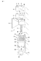
図1は電動式射出成形機の構成を示す図で、射出成形機本体1は、ホッパ2を備えた円筒形状のバレル3内に、射出スクリュ4を回転自在にかつ進退可能に挿通配置している。前記バレル3の後部は前記ホッパ2と連通し、このホッパ2から合成樹脂材料が投入されるようになっている。
Hereinafter, an embodiment of the present invention will be described with reference to the drawings. This embodiment will be described as applied to a control device for an electric injection molding machine.
FIG. 1 is a diagram showing the configuration of an electric injection molding machine. An injection molding machine
前記バレル3の外周に複数のヒータ(図示せず)を所定の間隔をあけて配置し、バレル外周部を加熱して投入された合成樹脂材料を溶融するようにしている。前記バレル3の先端部には溶融樹脂を射出するための射出ノズル5が形成されている。前記バレル3の温度は溶融樹脂の溶融度合いが先端部に向かって徐々に大きくなるように制御される。
A plurality of heaters (not shown) are arranged on the outer periphery of the
前記射出スクリュ4は射出用サーボモータ6によって回転駆動するとともに進退動作するようになっている。すなわち、前記射出用サーボモータ6の回転駆動力を、プーリ7、タイミングベルト8、タイミングプーリ9からなる伝達機構を介して、サーボブラケット10に回転自在に配置されたボールねじ軸11に伝達するように構成されている。そして、前記ボールねじ軸11にボールナット12を螺合し、このボールナット12がスラストボックス13にボルト結合されている。さらに、このスラストボックス13に前記射出スクリュ4の後端部を、回転自在に設けられたS軸やベアリング(図示せず)を介して回転自在に結合している。
The injection screw 4 is rotationally driven by an injection servo motor 6 and moves back and forth. That is, the rotational driving force of the injection servo motor 6 is transmitted to a ball screw shaft 11 rotatably disposed on the
前記スラストボックス13に回転自在に結合されたS軸に対し、タイミングプーリ14を結合配置し、このタイミングプーリ14とタイミングベルト15とプーリ16とからなる伝達機構を介して計量用サーボモータ17を結合し、この計量用サーボモータ17の回転駆動力を、伝達機構を介してS軸に伝達するようになっている。これにより、計量用サーボモータ17の回転は、射出スクリュ4に計量動作を行わせる回転として伝達される。
A
前記バレル3の前方には、金型18及びこの金型18の開閉及び型締めを行う装置19が配置されている。そして、前記射出スクリュ4の先端部4aは、バレル3の先端部に形成された射出ノズル5を前記金型18のノズル口18aへ押圧当接させた際に、前進動作してバレル3内で生成した溶融樹脂を射出ノズル5から射出して金型キャビティ20内へ充填するように構成されている。
In front of the
前記金型18の開閉及び型締めを行う装置19は、金型18の一方を支持する固定盤21に対し、タイバー22を介して金型18の他方を支持する可動盤23を移動自在に設けるとともにこの可動盤23をトグル式型締め機構24を介してトグル機構支持盤25に取り付けている。そして、前記トグル機構支持盤25にトグル式型締め機構24を駆動するための型締め用サーボモータ26を取り付けている。27はトグル式型締め機構24による型厚を調整する型厚調整機構である。
The device 19 for opening and closing and clamping the
この電動式射出成形機は、先ず、型締め用サーボモータ26を駆動して金型18の型閉じを開始するとともにバレル3の射出ノズル5を金型18のノズル口18aへ押圧当接させる。次いで、計量用サーボモータ17を駆動して射出する溶融樹脂の計量を行った後、射出用サーボモータ6を駆動して射出スクリュ4を前進させ金型キャビティ20内に溶融樹脂の射出充填を行う。
In this electric injection molding machine, first, the
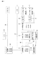
この電動式射出成形機本体1の制御装置は、図2に示すように、CPU、ROM、RAMを有し、射出成形機本体の管理、監視を行い、各部を制御する主制御部31を備えている。また、CPU、ROM、RAMを有し、射出成形機本体の動作順序を制御するシーケンス処理部32、CPU、ROM、RAMを有し、前記射出用サーボモータ6及び計量用サーボモータ17を制御するサーボ指令部33を備えている。前記主制御部31、シーケンス処理部32、サーボ指令部33はバスライン34によって互いに電気的に接続している。
As shown in FIG. 2, the control device for the electric injection molding machine
前記サーボ指令部33は、サーボアンプ35を制御して射出用サーボモータ6を駆動する。そして、射出用サーボモータ6の回転や電流値を検出部36で検出している。前記サーボ指令部33は、検出部36から検出信号を取り込んで前記射出スクリュ4の移動位置や回転速度やモータの電流値を検出し、それに基づいて射出用サーボモータ6を制御するフィードバック制御を行う。
The
また、前記サーボ指令部33は、サーボアンプ37を制御して計量用サーボモータ17を駆動する。そして、計量用サーボモータ17の回転や電流値を検出部38で検出している。前記サーボ指令部33は、検出部38から検出信号を取り込んで前記射出スクリュ4の移動位置や回転速度やモータの電流値を検出し、それに基づいて計量用サーボモータ17を制御するフィードバック制御を行う。
前記シーケンス処理部32には、I/Oバス39を介してI/O40等が電気的に接続されている。
The
An I /
前記主制御部31は、通信インターフェース部を備え、この通信インターフェース部に、CPU、ROM、RAM、汎用OS(オペレーティングシステム)を有するHMI(ヒューマンマシンインターフェース)部41をイーサネット(登録商標)等のLAN42によって接続している。前記HMI部41は、例えば、パーソナルコンピュータからなり、液晶ディスプレイの画面上にタッチパネルを配置したタッチパネル付表示部43の表示部に接続し、この表示部を表示制御する。
The
また、前記主制御部31は、複数の機械的な操作スイッチを設けた操作パネル部44をケーブル45によって接続し、また、前記タッチパネル付表示部43のタッチパネルをケーブル46によって接続し、さらに、前記バレル3の外周部に配置したヒータによるバレルの温度を制御する温度制御部47をケーブル48によって接続している。
Further, the
前記HMI部41は、図3に示すように、制御部本体を構成するCPU51、プログラムデータを格納したROM52、データ処理に使用するメモリ等を設けたRAM53、LAN42を介して主制御部31と通信を行う通信インターフェース(I/F)54、前記タッチパネル付表示部43の表示部を表示制御する表示コントローラ55、汎用OS等を格納したコンパクトフラッシュ(登録商標)カードやハードディスクなどの不揮発性記憶媒体を使用した記憶装置56、光ディスク等の外部記憶媒体57と接続し、この外部記憶媒体57とデータの通信を行う記憶媒体インターフェース(I/F)58を設け、互いにバスライン59によって電気的に接続している。前記記憶装置56には、計測データやこの計測データをもとに統計処理した統計データを記憶する記憶部が形成されている。
As shown in FIG. 3, the
前記タッチパネル付表示部43は、前記HMI部41によって表示コントローラ55を介して表示部が表示制御される。そして、前記タッチパネル付表示部43のタッチパネル操作によるキー信号が前記主制御部31に入力される構成になっており、主制御部31では入力したキー信号のうち、HMI部41で必要な信号を、LAN42を介してHMI部41に送信するようにしている。
The display unit with
前記主制御部31は、CPU、ROM、RAMによって、図4に示すように、成形品を成形する毎に、金型18(金型キャビティ20内)への溶融樹脂の充填時間、バレル3での溶融樹脂の計量時間、金型18での成形品の取出し時間、1つの成形品を成形するのに要するサイクル時間、保圧圧力等のモニタリング対象を計測する計測手段311と、この計測手段311が計測したモニタリング対象毎の計測データを予め設定した成形個数分前記記憶装置56の記憶部に記憶させるためにHMI部41への出力制御を行う計測データ制御手段312と、前記記憶装置56の記憶部に記憶した成形個数の範囲内で統計対象個数を設定して統計データの表示を前記HMI部41へ指示する第1の指示手段313と、前記記憶装置56の記憶部の計測データを使用せずにこれから成形される成形品の計測データを使用して統計データの表示を前記HMI部41へ指示する第2の指示手段314と、この第2の指示手段314による統計データの表示指示があると、前記計測手段311が計測したモニタリング対象毎の計測データから所望の統計データを算出して前記記憶装置56の記憶部に記憶させるためにHMI部41への出力制御を行う統計データ制御手段315を備えている。なお、前記第1、第2の指定手段313、314はタッチパネル付表示部43のタッチパネルも使用している。
As shown in FIG. 4, the
前記計測手段311は、充電時間、計量時間、取出し時間、サイクル時間については個々にタイマを使用して計測し、保圧圧力については圧力計を使用して計測するなど、それぞれのモニタリング対象に応じた方法で計測するようになっている。 The measuring means 311 measures the charging time, the metering time, the take-out time, and the cycle time individually using a timer, and measures the holding pressure using a pressure gauge. It comes to measure by the method.
前記HMI部41は、CPU、ROM、RAMによって、図5に示すように、年月日時刻を秒単位で計時する計時手段411と、前記主制御部31の計測データ制御手段312から計測データを受信すると計時手段411が計時した年月日時刻を付して前記記憶装置56の記憶部に記憶する計測データ記憶手段412と、前記主制御部31の第1の指示手段313から統計データの表示指示があると、前記記憶装置56の記憶部から設定した統計対象個数分の計測データを読み出して所望の統計データを算出し、この算出した統計データを前記タッチパネル付表示部43に表示させるために出力する第1の統計データ出力手段413と、前記主制御部31の統計データ制御手段315から統計データを受信すると計時手段411が計時した年月日時刻を付して前記記憶装置56の記憶部に記憶する統計データ記憶手段414と、前記記憶装置56の記憶部に記憶した統計データが設定した成形個数に達すると、記憶装置56の記憶部から統計データを読み出して前記タッチパネル付表示部43に表示させるために出力する第2の統計データ出力手段415を備えている。
As shown in FIG. 5, the
このような構成においては、成形品を成形する時には、タッチパネル付表示部43の表示部に成形条件の設定を選択する画面が表示されている状態でタッチパネルをタッチ操作して成形条件の設定を選択すると、表示部には成形条件を設定する画面が表示される。そして、作業者はこの設定画面上で操作を行い、射出成形の作業に先立って成形条件の設定や確認を行う。
In such a configuration, when molding a molded product, the touch panel is operated to select the molding condition setting while the screen for selecting the molding condition setting is displayed on the display unit of the
成形条件の設定が終了すると射出成形機本体1を制御して射出成形が開始される。射出成形においては、主制御部31は温度制御部47を制御してホッパ2からバレル3内に投入された合成樹脂材料をヒータによる加熱によって溶融し、シーケンス処理部32及びサーボ指令部33を制御する。これにより、先ず、計量サーボモータ17が駆動して射出スクリュ4を移動させて射出する溶融樹脂量を計量する。次に、射出用サーボモータ6が駆動して射出スクリュ4を前進させ、先端部4aで溶融樹脂を射出ノズル5へ押出す。これにより、射出ノズル5から金型18のノズル口18aに溶融樹脂が射出され、金型キャビティ20内に充填される。充填が終了すると、金型18の開閉及び型締めを行う装置19が動作して、金型18をバレル3から離間させるとともに金型18を開放し、成形された成形品が取出される。そして、1つの成形品が成形されるのを1ショットとし、この1ショットに要する時間をサイクル時間として成形が繰り返される。
When the setting of molding conditions is completed, the injection molding machine
この各サイクルにおいて主制御部31の計測手段311により、金型18への溶融樹脂の充填時間、バレル3における溶融樹脂の計量時間、金型18での成形品の取出し時間、サイクル時間、保圧圧力等が計測される。そして、1つの成形品を成形するときの、充電時間、計量時間、取出し時間、サイクル時間、保圧圧力等の計測データを1ショットの計測データとし、成形品単位、すなわち、ショット単位で計測データが計測データ制御手段312によりHMI部41へ出力される。HMI部41では1ショットの計測データを受信すると計測データ記憶手段412が、計時手段411が計時した年月日時刻を付して記憶装置56の記憶部に記憶する。こうして、成形品の成形が繰り返される毎にショット単位の計測データが記憶装置56に記憶される。そして、記憶装置56の記憶部は、1000ショット分の計測データを記憶する容量に設定され、記憶部に1000ショット分の計測データが記憶されると、それ以後は、一番古い計測データが消去されてから新しい計測データが記憶される。
In each cycle, the measurement means 311 of the
このような成形動作において、例えば、L統計を選択して現在のショット(2001ショット目)から5000ショットまでの、3000ショットについてモニタし、計測データに基づいて統計データを見たいときには、タッチパネル付表示部43のタッチパネルを操作して表示部に図6に示すようなL統計表示を行わせる。そして、画面上においてサンプル数「3000」ショットを入力して開始キーAを操作すると、主制御部31の第2の指示手段314がHMI部41に対して2001ショット目から5000ショットまでの統計データの表示の指示を行う。
In such a molding operation, for example, when L statistics are selected and 3000 shots from the current shot (2001 shot) to 5000 shots are monitored, and statistical data is to be viewed based on the measurement data, a display with a touch panel is provided. The touch panel of the
このときには主制御部31では、統計データ制御手段315が動作して計測手段311が計測した成形品の計測データから所望の統計データを算出して記憶装置56の記憶部に記憶させるためにHMI部41への出力制御を行う。HMI部41では統計データ制御手段315から統計データを受信すると、統計データ記憶手段414が統計データに計時手段411が計時した年月日時刻を付して記憶装置56の記憶部に1ショットの統計データとして記憶する。こうして、記憶装置56の記憶部には成形品毎の統計データが順次記憶される。
At this time, the
HMI部41の第2の統計データ出力手段415は、記憶装置56の記憶部から統計データを読み出してタッチパネル付表示部43へ出力する。こうして、タッチパネル付表示部43には、モニタリング対象である充填時間、計量時間、取出し時間、サイクル時間、保圧圧力等についての統計データが、例えば、トレンドL統計として、基準値に対してどのように変動しているかを示すグラフBの形式で表示される。なお、表示画面には1000ショット分の統計データが表示される。また、その統計データがどの時刻のものか分かるように時刻も表示される。
The second statistical
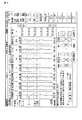
また、表示画面をL統計結果に切替えると、図7に示すような、充填時間、計量時間、取出し時間、サイクル時間、保圧圧力等について、最新ショットのデータ、最大値、最小値、平均、変動幅、分布率、標準偏差などの項目毎の統計データが数値データとして表示される。そして、この統計表示処理は、成形品の成形が3000ショット分行われると終了する。 When the display screen is switched to the L statistical result, as shown in FIG. 7, the latest shot data, maximum value, minimum value, average, filling time, weighing time, take-out time, cycle time, holding pressure, etc. Statistical data for each item such as fluctuation range, distribution rate, standard deviation, etc. is displayed as numerical data. And this statistical display process is complete | finished when shaping | molding of a molded article is performed for 3000 shots.
このように、これから成形する成形品の計測データを元に統計処理した結果をグラフや数値データで表示できるので、成形品の成形状態を確認することができる。そして、3000ショット分という多数の成形品の成形状態を確認できるので、統計の対象となる成形品の個数の量が多く、量産品生産時の成形品質管理には適している。そして、この場合は成形品の成形時の品質管理を充分に高めることができる。なお、ここではサンプルショット数を3000に設定したが、この統計処理においてはサンプルショット数を大きく設定することが可能であり、例えば、サンプルショット数を99999まで設定するということもできる。 Thus, since the result of statistical processing based on the measurement data of the molded product to be molded can be displayed as a graph or numerical data, the molded state of the molded product can be confirmed. Since the molding state of a large number of molded products corresponding to 3000 shots can be confirmed, the number of molded products to be statistics is large, which is suitable for molding quality control during mass production. In this case, quality control at the time of molding of the molded product can be sufficiently enhanced. Here, the number of sample shots is set to 3000. However, in this statistical process, the number of sample shots can be set large. For example, the number of sample shots can be set up to 99999.
また、記憶装置56の記憶部には、過去1000ショット分の計測データを記憶できる構成になっているので、例えば、今成形している成形品の過去500ショット分の統計を見たいときには、タッチパネル付表示部43のタッチパネルを操作して表示部に図8に示すような統計表示を行わせる。そして、画面上において開始「500」ショットを入力し、終了「1000」ショットを入力して確定キーCを操作すると、主制御部31の第1の指示手段313がHMI部41に対して記憶装置56の記憶部に記憶した1000ショットのうち、最新の500ショットの計測データを使用して統計データを算出し表示する指示を行う。
Further, the storage unit of the
これにより、HMI部41の第1の統計データ出力手段413は、記憶装置56の記憶部から最新の500ショット分の計測データを読み出して所望の統計データを算出し、この算出した統計データをタッチパネル付表示部43に出力する。こうして、タッチパネル付表示部43には、モニタリング対象である充填時間、計量時間、取出し時間、サイクル時間、保圧圧力等の統計データが図8に示すようにタッチパネル付表示部43に直ちに表示される。すなわち、タッチパネル付表示部43に、例えばトレンドS統計として、基準値に対してどのように変動しているかを示すグラフDの形式で表示される。また、この画面において品質モニタの項目を選択すると、図9に示すように表示画面の一部が切り替わり、グラフDとともに品質を示す数値データEも表示させることができる。
As a result, the first statistical data output means 413 of the
このように、過去の計測データを使用して成形品の成形状態を直ちに確認したいときには、1000ショット以下のショット数を指定することで記憶装置56の記憶部に記憶した過去の計測データを使用して短時間で統計データを表示させることができる。従って、過去の成形品のある区間の統計データを確認する場合に適している。この場合も統計データを確認することで成形品の成形時の品質管理を充分に高めることができる。
なお、この実施の形態では、タッチパネル付表示部をHMI部とは別体に設けたものについて述べたが、HMI部と一体であってもよい。
As described above, when it is desired to immediately confirm the molding state of the molded product using the past measurement data, the past measurement data stored in the storage unit of the
In this embodiment, the display unit with a touch panel is provided separately from the HMI unit. However, the display unit with a touch panel may be integrated with the HMI unit.
1…射出成形機本体、18…金型、31…主制御部、311…計測手段、312…計測データ制御手段、313…第1の指示手段、314…第2の指示手段、315…統計データ制御手段、41…HMI(ヒューマンマシンインターフェース)部、413…第1の統計データ出力手段、415…第2の統計データ出力手段、43…タッチパネル付表示部、51…CPU、56…記憶装置。
DESCRIPTION OF
Claims (1)
成形品を成形する毎に、金型への溶融樹脂の充填時間、バレルでの溶融樹脂の計量時間、金型での成形品の取出し時間、1つの成形品を成形するのに要するサイクル時間等のモニタリング対象を計測する計測手段と、記憶部と、前記計測手段が計測したモニタリング対象毎の計測データを予め設定した成形個数分前記記憶部に記憶させる制御を行う計測データ制御手段と、画面表示する表示部と、前記記憶部に記憶した成形個数の範囲内で統計対象個数を設定して統計データの表示を指示する第1の指示手段と、この第1の指示手段による統計データの表示指示があると、前記記憶部から設定した統計対象個数分の計測データを読み出して所望の統計データを算出し、この算出した統計データを前記表示部で表示させるために出力する第1の統計データ出力手段と、前記記憶部の計測データを使用せずにこれから成形される成形品の計測データを使用した統計データの表示を指示する第2の指示手段と、この第2の指示手段による統計データの表示指示があると、前記計測手段が計測したモニタリング対象毎の計測データから直ちに所望の統計データを算出して前記記憶部に記憶させる制御を行う統計データ制御手段と、前記記憶部から統計データを読み出して前記表示部で表示させるために出力する第2の統計データ出力手段を備え、前記第1の統計データ出力手段および前記第2の統計データ出力手段は、統計データを所望の成形個数の範囲で前記表示部にトレンド形式で表示させることを特徴とする射出成形機の制御装置。 In an injection molding machine that heats and melts a synthetic resin material in a barrel, measures it, and injects it into a mold from an injection nozzle to form a molded product.
Each time a molded product is molded, the molten resin filling time in the mold, the molten resin metering time in the barrel, the removal time of the molded product in the mold, the cycle time required to mold one molded product, etc. A measuring means for measuring the monitoring object, a storage part, a measurement data control means for controlling the storage part to store measurement data for each monitoring object measured by the measuring means in a preset number of moldings, and a screen display A display unit for displaying, a first instruction unit for instructing display of statistical data by setting the number of statistical objects within the range of the number of moldings stored in the storage unit, and an instruction for displaying statistical data by the first instruction unit If there is, the measurement data for the number of statistical objects set from the storage unit is read, desired statistical data is calculated, and the calculated statistical data is output for display on the display unit According to the second instruction means for instructing the display of the statistical data using the measurement data of the molded product to be molded without using the measurement data of the storage unit, and the second instruction means When there is an instruction to display statistical data, statistical data control means for performing control for immediately calculating desired statistical data from the measurement data for each monitoring object measured by the measurement means and storing the data in the storage unit, and the storage unit Second statistical data output means for reading out the statistical data and outputting it for display on the display unit , wherein the first statistical data output means and the second statistical data output means provide statistical data in a desired shape. A control apparatus for an injection molding machine , wherein the display unit displays a trend form in a range of the number .
Priority Applications (1)
| Application Number | Priority Date | Filing Date | Title |
|---|---|---|---|
| JP2005133160A JP4648076B2 (en) | 2005-04-28 | 2005-04-28 | Control device for injection molding machine |
Applications Claiming Priority (1)
| Application Number | Priority Date | Filing Date | Title |
|---|---|---|---|
| JP2005133160A JP4648076B2 (en) | 2005-04-28 | 2005-04-28 | Control device for injection molding machine |
Publications (2)
| Publication Number | Publication Date |
|---|---|
| JP2006305932A JP2006305932A (en) | 2006-11-09 |
| JP4648076B2 true JP4648076B2 (en) | 2011-03-09 |
Family
ID=37473369
Family Applications (1)
| Application Number | Title | Priority Date | Filing Date |
|---|---|---|---|
| JP2005133160A Active JP4648076B2 (en) | 2005-04-28 | 2005-04-28 | Control device for injection molding machine |
Country Status (1)
| Country | Link |
|---|---|
| JP (1) | JP4648076B2 (en) |
Families Citing this family (3)
| Publication number | Priority date | Publication date | Assignee | Title |
|---|---|---|---|---|
| JP5388413B2 (en) * | 2006-12-25 | 2014-01-15 | 東洋機械金属株式会社 | Molding machine |
| JP6914759B2 (en) * | 2017-07-11 | 2021-08-04 | 株式会社ユーシン精機 | Molded product take-out machine or operating status display system of molding machine |
| EP4252999A1 (en) | 2022-03-31 | 2023-10-04 | Yushin Precision Equipment Co. , Ltd. | Apparatus for taking out molded product |
Citations (10)
| Publication number | Priority date | Publication date | Assignee | Title |
|---|---|---|---|---|
| JPS6237121A (en) * | 1985-08-12 | 1987-02-18 | Sumitomo Heavy Ind Ltd | Quality control monitor for injection molding machine |
| JPH02241718A (en) * | 1989-03-15 | 1990-09-26 | Minolta Camera Co Ltd | Analyzing device of molding condition of molder |
| JPH03199025A (en) * | 1989-12-28 | 1991-08-30 | Toyo Mach & Metal Co Ltd | Measure data processing system in injection molding machine |
| JPH0623818A (en) * | 1992-07-06 | 1994-02-01 | Toyo Mach & Metal Co Ltd | Measured data processing device for injection molding machine |
| JPH06155540A (en) * | 1992-11-20 | 1994-06-03 | Fanuc Ltd | Molding information display device of injection molding machine |
| JPH07205247A (en) * | 1994-01-13 | 1995-08-08 | Sumitomo Heavy Ind Ltd | Method and apparatus for analyzing analog waveform of injection molding machine |
| JP2000326380A (en) * | 1999-05-19 | 2000-11-28 | Meiki Co Ltd | Method for totalizing control item data of molding machine |
| JP2004155125A (en) * | 2002-11-07 | 2004-06-03 | Nissei Plastics Ind Co | Display method for molding data of molding machine and molding data control system |
| JP2004230901A (en) * | 2004-04-27 | 2004-08-19 | Sumitomo Heavy Ind Ltd | Method and device for monitoring injection molding machine |
| JP2006305933A (en) * | 2005-04-28 | 2006-11-09 | Toshiba Mach Co Ltd | Control device of injection molding machine |
-
2005
- 2005-04-28 JP JP2005133160A patent/JP4648076B2/en active Active
Patent Citations (10)
| Publication number | Priority date | Publication date | Assignee | Title |
|---|---|---|---|---|
| JPS6237121A (en) * | 1985-08-12 | 1987-02-18 | Sumitomo Heavy Ind Ltd | Quality control monitor for injection molding machine |
| JPH02241718A (en) * | 1989-03-15 | 1990-09-26 | Minolta Camera Co Ltd | Analyzing device of molding condition of molder |
| JPH03199025A (en) * | 1989-12-28 | 1991-08-30 | Toyo Mach & Metal Co Ltd | Measure data processing system in injection molding machine |
| JPH0623818A (en) * | 1992-07-06 | 1994-02-01 | Toyo Mach & Metal Co Ltd | Measured data processing device for injection molding machine |
| JPH06155540A (en) * | 1992-11-20 | 1994-06-03 | Fanuc Ltd | Molding information display device of injection molding machine |
| JPH07205247A (en) * | 1994-01-13 | 1995-08-08 | Sumitomo Heavy Ind Ltd | Method and apparatus for analyzing analog waveform of injection molding machine |
| JP2000326380A (en) * | 1999-05-19 | 2000-11-28 | Meiki Co Ltd | Method for totalizing control item data of molding machine |
| JP2004155125A (en) * | 2002-11-07 | 2004-06-03 | Nissei Plastics Ind Co | Display method for molding data of molding machine and molding data control system |
| JP2004230901A (en) * | 2004-04-27 | 2004-08-19 | Sumitomo Heavy Ind Ltd | Method and device for monitoring injection molding machine |
| JP2006305933A (en) * | 2005-04-28 | 2006-11-09 | Toshiba Mach Co Ltd | Control device of injection molding machine |
Also Published As
| Publication number | Publication date |
|---|---|
| JP2006305932A (en) | 2006-11-09 |
Similar Documents
| Publication | Publication Date | Title |
|---|---|---|
| US7346425B2 (en) | Control device for use in injection molding machine | |
| JP4676242B2 (en) | Control device for injection molding machine | |
| EP3587067B1 (en) | Injection molding system | |
| JP4594160B2 (en) | Control device for injection molding machine | |
| JP4829522B2 (en) | Control device for injection molding machine | |
| JP4648076B2 (en) | Control device for injection molding machine | |
| JP4738883B2 (en) | Control device for injection molding machine | |
| JP4585371B2 (en) | Control device for injection molding machine | |
| US20150140148A1 (en) | Controller for injection molding machine | |
| KR20190104117A (en) | Injection molding machine | |
| JP5629157B2 (en) | Automatic operation method of injection molding machine | |
| JP2006297746A (en) | Controller for injection molding machine | |
| JP2011005870A (en) | Controller of injection molding machine | |
| JP4763081B1 (en) | Injection molding machine having weighing back pressure setting means | |
| JP2006305815A (en) | Control device of injection molding machine | |
| JP6289917B2 (en) | Injection molding machine | |
| JP2004142204A (en) | Injection-molding machine and method for measuring resin viscosity in injection-molding machine | |
| JPH10278091A (en) | Method and apparatus for injection molding | |
| JP5653599B2 (en) | Molding condition setting screen, molding condition setting device, and molding condition setting method | |
| JP5068848B2 (en) | Control device for injection molding machine | |
| JP2009018485A (en) | Injection molding method and injection molding device | |
| JP5806374B2 (en) | Automatic operation method of injection molding machine | |
| JPH0547382B2 (en) | ||
| JP2006305778A (en) | Control device of injection molding machine | |
| JP2006305777A (en) | Control device of injection molding machine |
Legal Events
| Date | Code | Title | Description |
|---|---|---|---|
| A621 | Written request for application examination |
Free format text: JAPANESE INTERMEDIATE CODE: A621 Effective date: 20080214 |
|
| A977 | Report on retrieval |
Free format text: JAPANESE INTERMEDIATE CODE: A971007 Effective date: 20100802 |
|
| A131 | Notification of reasons for refusal |
Free format text: JAPANESE INTERMEDIATE CODE: A131 Effective date: 20100824 |
|
| A521 | Written amendment |
Free format text: JAPANESE INTERMEDIATE CODE: A523 Effective date: 20100915 |
|
| TRDD | Decision of grant or rejection written | ||
| A01 | Written decision to grant a patent or to grant a registration (utility model) |
Free format text: JAPANESE INTERMEDIATE CODE: A01 Effective date: 20101130 |
|
| A01 | Written decision to grant a patent or to grant a registration (utility model) |
Free format text: JAPANESE INTERMEDIATE CODE: A01 |
|
| A61 | First payment of annual fees (during grant procedure) |
Free format text: JAPANESE INTERMEDIATE CODE: A61 Effective date: 20101209 |
|
| FPAY | Renewal fee payment (event date is renewal date of database) |
Free format text: PAYMENT UNTIL: 20131217 Year of fee payment: 3 |
|
| R150 | Certificate of patent or registration of utility model |
Ref document number: 4648076 Country of ref document: JP Free format text: JAPANESE INTERMEDIATE CODE: R150 Free format text: JAPANESE INTERMEDIATE CODE: R150 |
|
| S533 | Written request for registration of change of name |
Free format text: JAPANESE INTERMEDIATE CODE: R313533 |
|
| R350 | Written notification of registration of transfer |
Free format text: JAPANESE INTERMEDIATE CODE: R350 |