JP4646341B2 - Recording device, recording and / or reproducing device - Google Patents
Recording device, recording and / or reproducing device Download PDFInfo
- Publication number
- JP4646341B2 JP4646341B2 JP20695798A JP20695798A JP4646341B2 JP 4646341 B2 JP4646341 B2 JP 4646341B2 JP 20695798 A JP20695798 A JP 20695798A JP 20695798 A JP20695798 A JP 20695798A JP 4646341 B2 JP4646341 B2 JP 4646341B2
- Authority
- JP
- Japan
- Prior art keywords
- unit
- recording
- external
- power
- external memory
- Prior art date
- Legal status (The legal status is an assumption and is not a legal conclusion. Google has not performed a legal analysis and makes no representation as to the accuracy of the status listed.)
- Expired - Fee Related
Links
Images


Description
【0001】
【発明の属する技術分野】
本発明は、記録媒体に対して情報信号の記録及び/又は再生を行う記録及び/又は再生装置に関する。
【0002】
【従来の技術】
従来、記録媒体に対して画像/音声信号の記録及び/又は再生を行う記録及び/又は再生装置が提供されている。
【0003】
この記録及び/又は再生装置としては、磁気テープに対して画像信号の記録及び/又は再生を行うビデオテープレコーダ(video tape recorder; VTR)が提供されている。このようなVTRとしては、画像信号の撮像を行うビデオカメラと一体として構成されるカメラ一体型VTR、いわゆるカムコーダが提供されている。
【0004】
カメラ一体型VTRには、動画を撮像する機能を備えるのはもちろん、静止画を撮像する機能を有するものがある。また、カメラ一体型VTRには、外部の機器と赤外線を用いて無線通信を行う機能を備えるものが提供されている。
【0005】
さらに、カメラ一体型VTRには、機能を拡張するための種々のアクセサリまたは外付けユニットが提供されている。例えば、カメラ一体型VTRに装着して、撮像した動画または静止画を、例えばフロッピーディスクに記録するような外付けユニットが提供されている。また、外付けユニットの装着部であるアクセサリシューに装着して用いられる、撮影用の光源であるビデオライトが提供されている。このような外付けユニットには、通常はカメラ一体型VTRの本体から電源が供給される。
【0006】
【発明が解決しようとする課題】
しかしながら、カメラ一体型VTRに、本体内蔵の部分や外付けユニットにより複数の機能を持たせ、しかも本体から電源を供給するとなると、全ての機能が働いた場合には消費電力が大きくなり、大容量の電源を要することになる。すなわち、大きな消費電力に対応するために、大きな電力供給能力を持ったバッテリーやACアダプターが必要になる。ここで、ACアダプターとは、家庭用のAC電源をDC数ボルトの電源に変換するアダプターである。
【0007】
しかし、カメラ一体型VTRのセットの最大電力に対応したバッテリーやACアダプターはコスト高になるし、通常動作時は過大な規格となる。また、電源を商品毎に用意すると必要とする電源の種類が増えて不便である。
【0008】
すなわち、カメラ一体型VTRの最大電力に応じて電源を用意すると、本体および外付けユニットでの最大電力に見合った供給能力を持ったACアダプターやバッテリーが必要となり、種類が増え、コストが増加し、製造、流通、ユーザーの全てに都合悪かった。
【0009】
本発明は、上述の実情に鑑みてなされるものであって、多くの機能部分に対して本体から電源を供給する記録及び/又は再生装置であって、これら機能部分の最大電力が電源の供給能力を超える場合にも、消費電力を電源の供給能力以内に抑制するような記録及び/又は再生装置を提供することを目的とする。
【0010】
【課題を解決するための手段】
上述の課題を解決するために、本発明に係る記録装置は、記録媒体に対して画像信号の記録を行い、外付けユニットの装着可能な記録装置において、上記外付けユニットの装着を検出する外付けユニット検出手段と、上記外付けユニットに対して電源を供給する電源供給手段と、上記電源供給手段を制御する制御手段とを備え、上記記録装置の上記記録媒体に画像信号を記録する記録機能が実行されていない場合に、上記外付けユニット検出手段が上記外付けユニットの装着を検出したときは、上記電源供給手段による上記外付けユニットへの電源供給が自動的にオンされ、上記記録媒体に対する上記記録機能が実行される場合に、上記外付けユニット検出手段が上記外付けユニットの装着を検出したときは、上記制御手段は上記電源供給手段による上記外付けユニットに対する電源供給を制限させる制御をし、上記外付けユニットは、情報を記録する記録手段である。
【0011】
また、本発明に係る記録装置は、記録媒体に対して画像信号の記録を行い、外付けメモリの装着可能な記録装置において、上記外付けメモリの装着を検出するメモリ検出手段と、上記外付けメモリへアクセスするアクセス手段と、上記アクセス手段を制御する制御手段とを備え、上記記録装置の上記記録媒体に画像信号を記録する記録機能が実行されていない場合に、上記メモリ検出手段が上記外付けメモリの装着を検出したときは、上記アクセス手段による上記外付けメモリへのアクセスが自動的にオンされ、上記記録装置の上記記録媒体に対する上記記録機能が実行されている場合、又は上記記録装置が上記記録媒体に対して上記記録機能を行うモードに入った場合に、上記メモリ検出手段が上記外付けメモリの装着を検出したときは、上記制御手段は上記アクセス手段による上記外付けメモリへのアクセスを制限させる制御をするものである。
【0012】
そして、本発明に係る記録及び/又は再生装置は、記録媒体に対して少なくとも画像信号の記録及び/又は再生を行い、さらに外付けメモリを装着することが可能であり、装着された外付けメモリに対して画像信号の記録及び/又は再生を行う記録及び/又は再生装置において、上記外付けメモリの装着を検出する外付けメモリ検出手段と、上記外付けメモリへの電源の供給を制限するための制御信号を送信する制御手段と、上記外付けメモリに対して電源を供給するとともに、上記制御手段からの制御信号に応じて、上記外付けメモリに供給される電源を制限するメモリパワーセーブ手段を備え、上記記録媒体に画像信号が記録されていない場合に、上記外付けメモリ検出手段が上記外付けメモリの装着を検出したときは、上記メモリパワーセーブ手段による上記外付けメモリへの電源の供給が自動的にオンされ、記録媒体に画像信号が記録される場合に、上記外付けメモリ検出手段が上記外付けメモリの装着を検出したときは、上記制御手段は、上記外付けメモリ検出手段からの検出結果に応じて上記メモリパワーセーブ手段に上記制御信号を送信し、上記メモリパワーセーブ手段による上記外付けメモリに対する電源の供給を制限させる制御をするものである。
【0013】
ここで、動作モードとは、操作に応じて切り換えられる装置の動作のモードである。記録及び/又は再生装置は、この記録及び/又は再生装置の本体および外付けユニットの両方に対して電源を供給する。そして、記録及び/又は再生装置は、動作モードに応じて、各部への電源の供給を制限することにより、消費電力の低減を図るものである。例えば、記録及び/又は再生装置が光源を備える場合には、光源の使用する動作モードか否かに応じて、光源への電源供給を制限する。
【0014】
【発明の実施の形態】
以下、本発明の好適な実施の形態について、図面を参照して説明する。本実施の形態として以下に挙げる記録及び/又は再生装置は、動画と共に静止画を記録することができるいわゆるカメラ一体型のビデオテープレコーダ(video tape recorder; VTR)である。
【0015】
すなわち、本実施の形態に係る記録及び/又は再生装置は、光学的な画像を画像信号に変換する部分と、テープ状の記録媒体に対して画像信号の記録及び/又は再生を行う部分との両方を備えるいわゆるカムコーダである。
【0016】
この記録及び/又は再生装置は、動画に限られず静止画も扱うことができ、外部に接続された外付けユニットのメディアに静止画を記録することができる。外部に接続されるメディアには、記録及び/又は再生装置の本体から電源を供給する。
【0017】
そして、記録及び/又は再生装置は、赤外線レーザ光等の赤外線によるインターフェースいわゆるIR(infrared)を備え、外部の機器と無線による光通信による交信が可能である。
【0018】
なお、本実施の形態においては、本実施の形態に特徴的である回路部分を中心に説明するために、この記録及び/又は再生装置の光学部分については説明を省略する。
【0019】
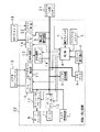
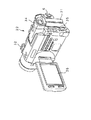
まず、本実施の形態の記録及び/又は再生装置の構成について、図1に示すブロック図を参照して説明する。また、本実施の形態の記録及び/又は再生装置の外観については、図2および図3に示すように、略々直方体状の筐体の本体22を有している。図2はビューファインダー34を起こした状態、図3は液晶画面36を開いた状態での装置の外観の斜視図である。
【0020】
本実施の形態の記録及び/又は再生装置は、図示しないビデオカメラから供給される画像信号を処理するカメラ信号処理部1と、ビデオ信号の処理を行うビデオ信号処理部2と、テープ走行部の駆動等を行う機構部であるメカデッキ3と、カセットの挿入を検出するカセット挿入検出部4と、静止画に対する信号処理を行う静止画信号処理部5とを有している。
【0021】
記録及び/又は再生装置には、図示しないビデオカメラから、被写体を撮像することにより得られた、例えば輝度信号や色差信号からなる画像信号が入力される。カメラ信号処理部1は、このようにビデオカメラから入力される信号に対して処理を行う。例えば、カメラ信号処理部1は、ビデオカメラから入力される信号に対して所定の変換を施す。
【0022】
ビデオ信号処理部2は、この記録及び/又は再生装置におけるビデオ信号に対する処理を行う部分である。例えば、ビデオ信号処理部2は、この記録及び/又は再生装置におけるビデオ信号について、記録媒体に記録及び/又は再生する際に、所定のフォーマットに従った変換を行う。
【0023】
メカデッキ3は、記録及び/又は再生装置に挿入され走行駆動されるテープ状記録媒体を駆動する機構部分である。メカデッキ3は、例えばモータおよびギア等から構成される機構を有し、後述する制御部から与えられる制御信号に応じて、記録媒体を所定の方向に所定の速度にて駆動する。
【0024】
カセット挿入検出部4は、テープ状記録媒体を収めるカセットが、この記録及び/又は再生装置に挿入されているか否かを検出する部分である。例えば、カセット挿入検出部4は、マイクロスイッチ等の検出素子によりカセットの挿入を検出し、その結果を後述する制御部に報告する。
【0025】
静止画処理部5は、ビデオカメラから送られた画像信号を受け取り、静止画としての処理を施す部分である。上述したように、この記録及び/又は再生装置は、ビデオカメラから入力される画像信号を動画として記録する機能と共に、画像信号を静止画として記録する機能を有している。例えば、静止画処理部5は、入力される画像信号を静止画として記録するために、入力された画像信号に所定のフォーマットに従った変換を施す。
【0026】
なお、図1においては、電源が供給される電源ラインを太線で、制御部からの制御信号が送られる制御ラインを破線で、制御部に送られる信号ラインを実線にて表している。また、この記録及び/又は再生装置の本体22に相当する回路部分を、周囲が破線の矩形の領域で示している。
【0027】
また、記録及び/又は再生装置は、モードの切り換えが入力されるファンクションスイッチ6と、入力操作を受け付ける操作スイッチ7と、この記録及び/又は再生装置の各部の制御を行う制御部8とを有している。
【0028】
ファンクションスイッチ6は、図2および図3に示すように、記録及び/又は再生装置の本体の図中の右側に配設され、モードの切り換えを受け付ける入力操作部である。ファンクションスイッチ6には、例えば、オフ/カメラモード/VTRモード/メモリモードなどのモード切り換えが入力される。
【0029】
例えば、カメラモードとは動画を撮影するモード、メモリモードとは静止画を撮影するモード、外付けメモリとの間で画像を処理するモードをそれぞれ示している。
【0030】
操作スイッチ7は、この記録及び/又は再生装置における記録及び/又は再生等の操作についてのユーザーからの入力操作を受け付けるヒューマンインターフェース(human interface; H/I)部であって、スイッチ、ボタン等を備えている。操作スイッチ7は、例えば、記録(record;REC)、再生(play back;PB)、巻き戻し(reward;REW)、早送り(fast forward;FF)、オートフォーカス(autofocus; AF)等の操作が入力される。また、操作スイッチ7においては、例えば、最後の場面を確認するレックレビュー(REC review)、正方向または逆方向に再生するサーチするエディットサーチ(edit search )、最後に撮影した部分に戻るエンドサーチ(end search)等についての操作も行われる。これによって、次の撮影開始点を探すことができる。
【0031】
制御部8は、この記録及び/又は再生装置の各部に対する制御を統括して行う部分である。制御部8は、予め設定された所定の手順に従い、ファンクションスイッチ6および操作スイッチ7からの入力操作および各部から与えられる検知結果に応じて、制御信号を発して各部を制御する。この制御部8としては、例えば、CPU、ROMおよびRAM等から構成されるいわゆるマイクロコントローラが用いられる。
【0032】
制御部8から各部に送られる制御信号は、破線にて示されるように、オートフォーカスパワーセーブ部10、ズームパワーセーブ部12、赤外通信パワーセーブ部14、シューパワーセーブ部16、およびメモリパワーセーブ部の19各部にそれぞれ送られる。
【0033】
この制御信号の方向とは逆に、制御部8に送られる検知信号等は、実線にて示さるように、カセット検出部4を介したメカデッキ3、ファンクションスイッチ6、操作スイッチ7、ビデオライト検出部17を介したビデオライト/フラッシュ15、メモリ検出部20を介した外付けメモリ18のそれぞれから送られている。
【0034】
制御部8においては、これら各部から与えられる検知信号等に応じて、各部にパワーセーブ等の制御信号を送る。すなわち、制御部8は、この記録及び/又は再生装置の現在の動作モードおよびこの記録及び/又は再生装置に対する外付けユニットの装着状態等に応じて、不要な部分への電源の供給を制限することにより、記録及び/又は再生装置の全体での消費電力の低減を図るように制御を行う。このような、消費電力の低減を図るパワーセーブの制御については、さらに後述する。
【0035】
なお、制御部8については、上記以外の他の部分へ制御信号を送ったり、検知信号等を送られたりすることもあるが、本実施の形態のパワーセーブとは関連が薄いの説明を省略した。
【0036】
さらに、記録及び/又は再生装置は、距離の調整、焦点合わせ等を行うオートフォーカス部9と、このオートフォーカス部9で消費される電力を低減するオートフォーカスパワーセーブ部10とを有している。
【0037】
オートフォーカス部9は、物体とその像との距離の変化に応じて光学系自身が、使用者の手を借りずに光学的、機械的、電気的に距離調節・焦点合わせの操作を行うものである。
【0038】
オートフォーカスパワーセーブ部10は、制御部8からの制御信号に応じて、オートフォーカス部9に供給される電源を制限する。例えば、オートフォーカス部9が使用されないときには、制御部8からの制御信号に従ってオートフォーカス部9への電源の供給を制限して電力の消費を低減する。
【0039】
なお、図中の太線の電源ラインにて示されるように、オートフォーカス部9およびオートフォーカスパワーセーブ部10においては、電源はオートフォーカスパワーセーブ部10を介してオートフォーカス部9に供給されている。
【0040】
そして、記録及び/又は再生装置は、映像サイズの拡大/縮小を行うズーム部11と、このズーム部11に対するパワーセーブの処理を行うズームパワーセーブ部12とを有している。
【0041】
ズーム部11は、電気的、光学的、機械的に画像の大きさを連続して拡大/縮小する部分である。
【0042】
ズームパワーセーブ部12は、制御部8からの制御信号に応じて、ズーム部11に供給される電源を制限する。例えば、ズーム部11が使用されないときには、制御部8からの制御信号に従ってズーム部11への電源の供給を制限して電力の消費を低減する。ズーム部11には、ズームパワーセーブ部12を介して電源が供給されている。
【0043】
また、記録及び/又は再生装置は、外部の機器と赤外線にて通信を行うインターフェース部である赤外通信部13と、この赤外通信部13に対するパワーセーブの処理を行う赤外通信パワーセーブ部14とを有している。
【0044】
赤外通信部13は、外部の機器との間で、所定の方式にて変調された赤外線を送信/受信することにより、この記録及び/又は再生装置と情報の伝送を行うインターフェース部である。例えば、赤外通信部13からは、外部の機器との間でビデオ/オーディオ信号が伝送される。この赤外通信部13は、例えば1W弱の電力を消費する。
【0045】
赤外通信パワーセーブ部14は、制御部8からの制御信号に応じて、赤外通信部13に供給される電源を制限する。例えば、赤外通信部13が使用されないときには、制御部8からの制御信号に従って赤外通信部13への電源の供給を制限して電力の消費を低減する。赤外通信部13には、赤外通信パワーセーブ部14を介して電源が供給されている。
【0046】
この記録及び/又は再生装置は、所定の外付けユニットの装着が可能である。図1においては、この記録及び/又は再生装置の本体22に対応する各部を周囲を破線にて示した矩形の内部に本体22に対応する部分を示し、本体22に装着可能な外付けユニットをこの矩形の外側に配置している。
【0047】
すなわち、この記録及び/又は再生装置は、図2および図3に示すように、筐体の外付けユニットの取り付け部であるアクセサリシュー(accessory shoe)32等を介して、ビデオライト等の外付けユニットを装着することができる。
【0048】
破線で示した矩形で示される記録及び/又は再生装置の本体22の外側に配された外付けユニットは、本体22に常に装着されているものではない。これら外付けユニットは、必要に応じて記録及び/又は再生装置の本体22に装着される。
【0049】
外付けユニットは、記録及び/又は再生装置の本体22に装着された際には、その外付けユニットが電源を消費する場合は、通常は記録及び/又は再生装置の本体22から電源が供給される。
【0050】
記録再生/装置の本体の筐体の略々上部に備えられるアクセサリシュー32には、例えば被写体を照射する光源の外付けユニットであるビデオライト/フラッシュ部15の装着が可能である。
【0051】
ビデオライト/フラッシュ部15においては、例えば、ビデオライトは動画を撮像する際に光を連続的に照射する光源であり、ビデオフラッシュは静止画を撮像する際に光を不連続に照射する光源である。このビデオライト/フラッシュ部15は、例えば4.2Wの電力を消費する。
【0052】
記録及び/又は再生装置は、このビデオライト/フラッシュ部15に対応する部分として、ビデオライト/フラッシュ部15の装着を検出するビデオライト検出部17と、ビデオライト/フラッシュ部15に対するパワーセーブの処理を行うシューパワーセーブ部16とを有している。
【0053】
ビデオライト検出部17は、アクセサリシュー32に対するビデオライト/フラッシュ部15の装着を検出する部分である。このビデオライト検出部17は、例えば、ビデオライト/フラッシュ部15から送られる識別情報(identifier; ID)を認識することにより、アクセサリシュー32に対するビデオライト/フラッシュ部15の装着を検知し、その結果を制御部8に報告する。
【0054】
シューパワーセーブ部16は、制御部8からの制御信号に応じて、アクセサリシュー32に供給する電源を制限する部分である。シューパワーセーブ部16は、アクセサリシュー32に例えばビデオライト/フラッシュ部15が装着された場合には、このビデオライト/フラッシュ部15を使用しないときには、制御部8からの制御信号に従ってアクセサリシュー32を介してビデオライト/フラッシュ部15に供給される電源を制限して電力の消費を低減する。
【0055】
すなわち、制御部8は、ビデオライト検出部17からの検知結果によりアクセサリシュー32にビデオライト/フラッシュ部15が装着されたことを認識するが、現在の動作モードにおいてビデオライト/フラッシュ部15が使用されない場合等でビデオライト/フラッシュ部15への電源の供給が不要な場合には、シューパワーセーブ部16にアクセサリシュー32に装着されたビデオライト/フラッシュ部15への電源を制限するように制御信号を送る。シューパワーセーブ部16は、この制御信号に応じて、アクセサリシュー32へ供給する電源を制限する。なお、この場合には、アクセサリシュー32に装着されたビデオライト/フラッシュ部15には、シューパワーセーブ部16を介して電源が供給される。
【0056】
シューパワーセーブ部16は、制御部8からの制御信号によりオン/オフの切り換えが可能なスイッチとして構成することができる。
【0057】
また、記録及び/又は再生装置は、情報を記憶する記憶手段である外付けメモリ18を外付けユニットとして装着可能である。
【0058】
外付けメモリ18は、記録及び/又は再生装置の本体22に装着されて、本体22から送られる情報を記憶する。この外付けメモリ18としては、情報を半導体素子に記憶する半導体記憶装置であってもよいし、情報を磁気的に記憶する磁気記憶装置であってもよい。すなわち、外付けメモリ18は、取り外し可能なメモリや記録メディアであって、記録及び/又は再生装置の本体22から電源が供給されるものである。
【0059】
例えば、外付けメモリ18は、図4に示すように、フロッピーディスクをメディアとして情報を記録するフロッピーディスクドライブとして構成される。この外付けメモリ18は、図2および図3に示した外付けメモリ接続部35にて本体22に接続される。
【0060】
記録及び/又は再生装置は、この外付けメモリ18に対応する部分として、外付けメモリ18の装着を検出するメモリ検出部20と、外付けメモリ18に対するパワーセーブの処理を行うメモリパワーセーブ部19とを有している。
【0061】
メモリ検出部20は、記録及び/又は再生装置の本体22に対する外付けメモリ18の装着を検出する部分である。このメモリ検出部20は、例えば、外付けメモリ18から送られる識別情報を認識することにより、記録及び/又は再生装置の本体22に対する外付けメモリ18の装着を検知し、その結果を制御部8に報告する。
【0062】
メモリパワーセーブ部19は、制御部8からの制御信号に応じて、外付けメモリ18に供給する電源を制限する部分である。メモリパワーセーブ部19は、記録及び/又は再生装置の本体22に例えば外付けメモリ18が装着された場合には、この外付けメモリ18を使用しないときには、制御部8からの制御信号に従って外付けメモリ18に供給される電源を制限して電力の消費を低減する。
【0063】
すなわち、制御部8は、メモリ検出部20からの検知結果により記録及び/又は再生装置の本体22に外付けメモリ18が装着されたことを認識するが、現在の動作モードにおいて外付けメモリ18が使用されない場合等で外付けメモリ18への電源の供給が不要な場合には、メモリセーブ部19に外付けメモリ18への電源を制限するように制御信号を送る。メモリパワーセーブ部19は、この制御信号に応じて、外付けメモリ18へ供給する電源を制限する。なお、記録及び/又は再生装置の本体22に装着された外付けメモリ18には、メモリパワーセーブ部19を介して電源が供給されている。
【0064】
メモリパワーセーブ部19は、制御部8からの制御信号によりオン/オフの切り換えが可能なスイッチとして構成することができる。
【0065】
さらに、記録及び/又は再生装置は、外部から電源を供給するACアダプター部または外部バッテリー部21を外付けユニットとして装着が可能である。
【0066】
ACアダプター部とは、例えば家庭用AC電源をDC数ボルトの電源に変換するものである。外部バッテリー部とは、例えば乾電池や蓄電池により構成され、所定電圧を電源として供給するものである。このACアダプター(外付けメモリ)21は、例えば12.6Wの電力を供給することができる。
【0067】
ACアダプター(外付けバッテリー)21は、図2に示すACアダプター(外付けバッテリー)装着部33に、図3に示すように装着される。なお、図3中に示されているのは外付けバッテリーである。
【0068】
記録及び/又は再生装置の本体22に装着された外付けユニットであるACアダプター部(外部バッテリー部)21から供給された電源は、図中の太線にて示される電源ラインを介して、カメラ信号処理部1、ビデオ信号処理部2、メカデッキ3、静止画信号処理部5、オートフォーカスセーブ部10、ズームパワーセーブ部12、赤外通信パワーセーブ部14、シューパワーセーブ部16、およびメモリパワーセーブ部19の各部に供給されている。
【0069】
そして、オートフォーカスパワーセーブ部10を介してオートフォーカス部9、ズームパワーセーブ部12を介してズーム部11、赤外通信パワーセーブ部14を介して赤外通信部13、シューパワーセーブ部16を介してビデオライト/フラッシュ部15、メモリパワーセーブ部19を介して外付けメモリ18に、それぞれパワーセーブについて制御可能な状態で電源が供給されているのは上述の通りである。
【0070】
なお、この記録及び/又は再生装置の他の部分にも、電源が供給されているが、本実施の形態に係るパワーセーブには関連が薄いので説明を省略した。
【0071】
この記録及び/又は再生装置における電力の消費は、通常のカメラ撮りの際には5.2Wであるが、オートフォーカス、ズームおよびテープイジェクトの際にはラッシュ電流のためにさらに最大5Wの電力を要する。これに、外付けユニット等で要する電力を加えると、ACアダプター(外付けユニット)21から供給することができる電力を上回ることになる。
【0072】
なお、上述の各パワーセーブ部、すなわちオートフォーカスパワーセーブ部10、ズームパワーセーブ部12、赤外通信パワーセーブ部14、シューパワーセーブ部16、および外付けメモリパワーセーブ部19は、オン/オフの切り換えスイッチの場合や、当該部分の機能が停止することによるパワーセーブの場合など、パワーセーブの態様には種々ある。
【0073】
続いて、本実施の形態における消費電力の低減であるパワーセーブについて説明する。
【0074】
本実施の形態では、パワーセーブとは、この記録及び/又は再生装置において、一定の機能を実現するときに、当該機能の実現に不要な部分への電力の供給を自動的に制限することにより、全体の電力を抑制するものである。
【0075】
例えば、記録及び/又は再生装置においては、動画を撮像するカメラモードにおいては、光源から光を照射することが必要ない程度に周囲が明るい場合には、ビデオライトは不要であるので、ビデオライトへの電源の供給は自動的に停止される。
【0076】
具体的には、本実施の形態の記録及び/又は再生装置においては、パワーセーブは次のような場合に実行される。
【0077】
第1の場合として、記録及び/又は再生装置においては、図示しないビデオカメラへの電源の供給をファンクションスイッチ6でオフ/オンするときや、メカデッキ3から記録媒体のテープを出し入れするときには大きな消費電力を要する。これは、メカデッキ3の初期化(イニシャライズ)に大きな電力を要するためである。
【0078】
第2の場合として、記録及び/又は再生装置においては、図示しないビデオカメラにて動画を撮影するカメラモードがファンクションスイッチで選択されている際に、ユーザーが操作スイッチ7を操作して、上述した、レックレビューやエディットサーチ、エンドサーチなどのビデオテープの検索(サーチ)の系統の動作を実行するときには大電力を要する。これは、メカデッキ3の変速動作や動作の切り換えの際に大電力を要するためである。
【0079】
第3の場合として、記録及び/又は再生装置においては、静止画を撮影するカメラモードや、画像を外付けメモリ18に対して記録及び/又は再生するメモリモードがファンクションスイッチ6にて選択されている際に、外付けメモリ18への書き込みや読み出しのアクセスの際に、メディアへのアクセスに大電力を要す。
【0080】
このような第1の場合から第3の場合には、記録及び/又は再生装置においては、次のようなパワーセーブが行われる。
【0081】
第1に、ビデオライト/フラッシュ部15に供給される電源がオフにされる。
【0082】
すなわち、この記録及び/又は再生装置のアクセサリシュー32にビデオライト/フラッシュ部15が装着されたことが、識別情報などによりビデオライト検出部17で検出されたら、通常は制御部8がシューパワーセーブ部16を介してアクセサリシュー32への電源をオンする。
【0083】
しかし、上述の第1の場合から第3の場合には、制御部8は、シューパワーセーブ部16を介してビデオライト/フラッシュ部15に供給される電源をオフする。これによって、ビデオライト/フラッシュ部15で消費される電力が低減される。
【0084】
第2に、オートフォーカスがオフにされる。
【0085】
すなわち、ユーザーが操作スイッチ7でオートフォーカスをオンにしていると、オートフォーカスパワーセーブ部10を介してオートフォーカス部9には電源が供給される。
【0086】
しかし、上述の第1の場合から第3の場合には、制御部8は、ユーザーが操作スイッチ7でオートフォーカス部9をオンにしていても、オートフォーカスパワーセーブ部10に作用して、オートフォーカス部9を動かさないで、電力を要さない制御をする。
【0087】
第3に、ズームがオフにされる。
【0088】
すなわち、ユーザーが操作スイッチ7でズームをオンにしていると、ズームパワーセーブ部12を介してズーム部11には電源が供給される。
【0089】
しかし、上述の第1の場合から第3の場合には、制御部8は、ユーザーが操作スイッチ7でズーム部11を動かそうとしても、ズームパワーセーブ部12に作用してズーム部11を動かさないように制御する。
【0090】
また、記録及び/又は再生装置においては、図示しないビデオカメラで動画を記録中や動画を記録するモードに入った際には電力を要する。これは、通常のカメラRECで、ビデオカメラからの画像信号をテープに記録するため、ビデオ信号処理部2やメカデッキ3で大電力を要するためである。
【0091】
これに対応するために、外付けメモリ18にアクセスしないことにする。
【0092】
すなわち、メモリ検出部20で外付けメモリ18のメディアが、この記録及び/又は再生装置の本体22に装着されたことが検出されても、制御部8は、メモリパワーセーブ部19にてパワーセーブを行って外付けメモリ18にアクセスしないよう制御する。
【0093】
外付けメモリ18にアクセスしないことにより外付けメモリ18の初期動作に必要な電力の消費が低減される。すなわち、外付けメモリ18をオフとすることにより外付けメモリ18に必要な例えば最大4.5Wの電力が低減される。
【0094】
なお、メモリパワーセーブ部19によるパワーセーブは、モード切り換えを行うファンクションスイッチ6の切り換えに連動させてもよい。
【0095】
さらに、記録及び/又は再生装置においては、ファンクションスイッチ6がカメラモードやメモリーモードのときにビデオライト/フラッシュ部15などで大電力を要する。
【0096】
これに対応するために、通常はユーザーが操作スイッチ7で赤外通信(IR)部13のオンを押圧すれば赤外通信部13がオンするが、メカデッキ3に記録媒体のテープのカセットが挿入されていることをカセット挿入検出部4が検出すると、制御部8は、赤外通信パワーセーブ部14を制御して赤外通信部13を強制的にオフとする。
【0097】
また、記録及び/又は再生装置の本体22に外付けメモリ18が装着されたことをメモリ検出部20が検出すれば、制御部8は、同様に赤外通信部13をオフとする。
【0098】
以上のように、本実施の形態の記録及び/又は再生装置においては、大電力を要する機能を使うときに不要な機能は、ユーザーが選択しなくても自動的にオフして、大電力を要する機能が重複しないようにするパワーセーブを実行するものである。
【0099】
すなわち、本実施の形態は、本体22に装着する外付けユニットに対して電源供給する記録及び/又は再生において、起こり得る最大消費電力が電源供給能力を越える場合でも、実仕様に支障のない範囲で一部の機能を自動的に止めて、供給能力以内に収まるようにするものである。
【0100】
なお、本実施の形態は、記録及び/又は再生装置としてカメラ一体型VTRについて具体例を示しながら示したが、機能の一部を削除したVTRについても応用できることはもちろんである。例えば、本実施の形態は、ビデオカメラを備えないようなVTRに対しても適用することができる。
【0101】
また、本実施の形態においては、ビデオライト/フラッシュ部15や外付けメモリ18が外付けタイプの例であるが、これらが本体22に内蔵されていてもよいことはいうまでもない。すなわち、本実施の形態は、外付けユニットを接続したときだけではなく、本体の内蔵部分のパワーセーブも行うものである。
【0102】
さらに、本実施の形態においては、記録及び/又は再生装置は外部の機器と赤外線を用いて無線にて通信を行う例を示したが、本発明はこれに限定されず、一般の光通信を利用することができることはいうまでもない。
【0103】
【発明の効果】
上述のように、本発明においては、各部からの検出結果および動作モードに応じて不要な部分への電源の供給を制限するので、最大電力が電源の供給能力を超える場合でも、消費電力を供給能力に収めることができる。
【0104】
具体例で示したような、多くの機能を持ったカメラ一体型VTRにおいて、全てが同時に動作した場合を想定すると、膨大な供給電力を持った外部電源が必要となるが、本発明により、そこそこの能力を持った電源でも使えるようになり、ポータブル機器にとってはメリットが大きい。
【図面の簡単な説明】
【図1】記録及び/又は再生装置の概略的な構成を示すブロック図である。
【図2】ビューファインダーを起こした状態の記録及び/又は再生装置の斜視図である。
【図3】液晶画面を開いた状態の記録及び/又は再生装置の斜視図である。
【図4】外付けメモリを装着した状態の記録及び/又は再生装置の斜視図である。
【符号の説明】
8 制御部、9 オートフォーカス部、10 オートフォーカスパワーセーブ部、11 ズーム部、12 ズームパワーセーブ部、15 ビデオライト/フラッシュ部、16 シューパワーセーブ部、18 外付けメモリ部、19 メモリパワーセーブ部、21 ACアダプター部(外部バッテリー部)[0001]
BACKGROUND OF THE INVENTION
The present invention relates to a recording and / or reproducing apparatus for recording and / or reproducing information signals on a recording medium.
[0002]
[Prior art]
2. Description of the Related Art Conventionally, a recording and / or reproducing apparatus for recording and / or reproducing an image / audio signal on a recording medium has been provided.
[0003]
As the recording and / or reproducing apparatus, a video tape recorder (VTR) that records and / or reproduces an image signal with respect to a magnetic tape is provided. As such a VTR, there is provided a so-called camcorder, a camera-integrated VTR configured integrally with a video camera that captures an image signal.
[0004]
Some camera-integrated VTRs have a function of capturing a moving image as well as a function of capturing a still image. A camera-integrated VTR is provided with a function of performing wireless communication with an external device using infrared rays.
[0005]
Further, various accessories or external units for extending functions are provided for the camera-integrated VTR. For example, an external unit is provided that is mounted on a camera-integrated VTR and records a captured moving image or still image on, for example, a floppy disk. There is also provided a video light that is a light source for photographing that is used by being attached to an accessory shoe that is a mounting portion of an external unit. Such an external unit is usually supplied with power from the main body of the camera-integrated VTR.
[0006]
[Problems to be solved by the invention]
However, if a camera-integrated VTR has multiple functions using internal parts and external units, and power is supplied from the main body, power consumption increases when all functions are activated, resulting in a large capacity. It will require a power supply. In other words, a battery or an AC adapter having a large power supply capability is required to cope with large power consumption. Here, the AC adapter is an adapter that converts a home AC power source into a DC several volt power source.
[0007]
However, the battery and the AC adapter corresponding to the maximum power of the camera-integrated VTR set are expensive and become an excessive standard during normal operation. In addition, if a power source is prepared for each product, the number of types of power sources required is inconvenient.
[0008]
In other words, if a power supply is prepared according to the maximum power of the camera-integrated VTR, an AC adapter and a battery with a supply capacity corresponding to the maximum power of the main unit and the external unit will be required, and the types will increase and the cost will increase. , Manufacturing, distribution, users were all inconvenient.
[0009]
The present invention has been made in view of the above circumstances, and is a recording and / or reproducing apparatus that supplies power from a main body to many functional parts, and the maximum power of these functional parts is the supply of power. An object of the present invention is to provide a recording and / or reproducing apparatus that suppresses power consumption within the power supply capability even when the capacity is exceeded.
[0010]
[Means for Solving the Problems]
In order to solve the above-described problems, a recording apparatus according to the present invention records an image signal on a recording medium, and is an external recording unit that can be mounted with an external unit. An attachment unit detecting means; a power supply means for supplying power to the external unit; and a control means for controlling the power supply means. Recording function for recording an image signal on the recording medium When the external unit detection means detects that the external unit is mounted when the external unit is not executed, the power supply to the external unit by the power supply means is automatically turned on, The above recording function for the recording medium When the external unit detection means detects the attachment of the external unit, the control means performs control to limit power supply to the external unit by the power supply means. The external unit is a recording means for recording information. .
[0011]
Further, the recording apparatus according to the present invention is a recording apparatus that records an image signal on a recording medium and is capable of mounting an external memory. An access means for accessing the memory; and a control means for controlling the access means. Recording function for recording an image signal on the recording medium When the memory detecting means detects the attachment of the external memory when the memory is not executed, access to the external memory by the access means is automatically turned on, and the recording device The recording function for the recording medium Or the recording device is Entered the mode to perform the recording function for the recording medium In this case, when the memory detection means detects the attachment of the external memory, the control means controls to restrict access to the external memory by the access means.
[0012]
The recording and / or reproducing apparatus according to the present invention can record and / or reproduce at least an image signal with respect to a recording medium, and can be further equipped with an external memory. In the recording and / or reproducing apparatus for recording and / or reproducing the image signal, the external memory detecting means for detecting the mounting of the external memory and the supply of power to the external memory are restricted. Control means for transmitting a control signal of While supplying power to the external memory, Memory power saving means for limiting the power supplied to the external memory in response to a control signal from the control means, and the external memory detection means when no image signal is recorded on the recording medium Detects the installation of the above external memory, Memory power saving means by External memory above Power to of When the supply is automatically turned on and an image signal is recorded on the recording medium, when the external memory detection unit detects the mounting of the external memory, the control unit detects the external memory detection unit. According to the detection result from the above memory power saving means The control signal is transmitted to the memory, and the control for restricting the power supply to the external memory by the memory power saving means is performed. Is.
[0013]
Here, the operation mode is a mode of operation of the apparatus that is switched according to an operation. The recording and / or reproducing apparatus supplies power to both the main body and the external unit of the recording and / or reproducing apparatus. Then, the recording and / or reproducing apparatus is intended to reduce power consumption by restricting the supply of power to each unit according to the operation mode. For example, when the recording and / or reproducing apparatus includes a light source, power supply to the light source is limited depending on whether the operation mode is used by the light source.
[0014]
DETAILED DESCRIPTION OF THE INVENTION
DESCRIPTION OF EXEMPLARY EMBODIMENTS Hereinafter, preferred embodiments of the invention will be described with reference to the drawings. The recording and / or reproducing apparatus described below as the present embodiment is a so-called camera-integrated video tape recorder (VTR) capable of recording a still image together with a moving image.
[0015]
That is, the recording and / or reproducing apparatus according to the present embodiment includes a part that converts an optical image into an image signal and a part that records and / or reproduces an image signal on a tape-shaped recording medium. It is a so-called camcorder having both.
[0016]
This recording and / or reproducing apparatus can handle not only moving images but also still images, and can record still images on media of an external unit connected to the outside. Power is supplied to the externally connected media from the main body of the recording and / or playback apparatus.
[0017]
The recording and / or reproducing apparatus includes an infrared interface such as an infrared laser beam, so-called IR (infrared), and can communicate with an external device by wireless optical communication.
[0018]
In the present embodiment, the description of the optical portion of the recording and / or reproducing apparatus will be omitted in order to mainly describe the circuit portion that is characteristic of the present embodiment.
[0019]
First, the configuration of the recording and / or reproducing apparatus according to the present embodiment will be described with reference to the block diagram shown in FIG. As for the appearance of the recording and / or reproducing apparatus of the present embodiment, as shown in FIGS. 2 and 3, it has a
[0020]
The recording and / or reproducing apparatus according to the present embodiment includes a camera signal processing unit that processes an image signal supplied from a video camera (not shown). 1 A video signal processing unit 2 that processes video signals, a mechanical deck 3 that is a mechanism unit that drives the tape running unit, a cassette
[0021]
The recording and / or reproducing apparatus receives an image signal made up of, for example, a luminance signal or a color difference signal, which is obtained by imaging a subject from a video camera (not shown). The camera signal processing unit 1 performs processing on the signal input from the video camera in this way. For example, the camera signal processing unit 1 performs predetermined conversion on a signal input from the video camera.
[0022]
The video signal processing unit 2 is a part that performs processing on the video signal in the recording and / or reproducing apparatus. For example, the video signal processing unit 2 performs conversion according to a predetermined format when recording and / or reproducing the video signal in the recording and / or reproducing apparatus on a recording medium.
[0023]
The mechanical deck 3 is a mechanism portion that drives a tape-shaped recording medium that is inserted into a recording and / or reproducing apparatus and driven to travel. The mechanical deck 3 has a mechanism composed of, for example, a motor and a gear, and drives the recording medium in a predetermined direction at a predetermined speed in accordance with a control signal given from a control unit described later.
[0024]
The cassette
[0025]
The still image processing unit 5 is a part that receives an image signal sent from a video camera and performs processing as a still image. As described above, this recording and / or reproducing apparatus has a function of recording an image signal input from a video camera as a moving image and a function of recording an image signal as a still image. For example, the still image processing unit 5 performs conversion according to a predetermined format on the input image signal in order to record the input image signal as a still image.
[0026]
In FIG. 1, a power line to which power is supplied is indicated by a thick line, a control line to which a control signal from the control unit is sent is indicated by a broken line, and a signal line to be sent to the control unit is indicated. solid line It is represented by. In addition, a circuit portion corresponding to the
[0027]
In addition, the recording and / or reproducing apparatus includes a
[0028]
As shown in FIGS. 2 and 3, the
[0029]
For example, what is camera mode? Video Shooting mode, memory What is a mode? Still image A mode for capturing images and a mode for processing images with an external memory are shown.
[0030]
The
[0031]
The control unit 8 is a part that performs overall control of each unit of the recording and / or reproducing apparatus. The control unit 8 controls each unit by issuing a control signal according to the input operation from the
[0032]
The control signal sent from the control unit 8 to each unit includes an autofocus
[0033]
Contrary to the direction of this control signal, the detection signal and the like sent to the control unit 8 are mechanical deck 3,
[0034]
In the control unit 8, a control signal such as power save is sent to each unit in accordance with a detection signal or the like given from each unit. That is, the control unit 8 restricts the supply of power to unnecessary portions according to the current operation mode of the recording and / or reproducing apparatus and the mounting state of the external unit with respect to the recording and / or reproducing apparatus. Thus, control is performed so as to reduce the power consumption of the entire recording and / or reproducing apparatus. Such power saving control for reducing power consumption will be described later.
[0035]
The control unit 8 may send a control signal to other parts other than the above, or may send a detection signal, etc., but the description is omitted because it is not related to the power save of this embodiment. did.
[0036]
Furthermore, the recording and / or reproducing apparatus includes an
[0037]
The
[0038]
The autofocus
[0039]
In the
[0040]
The recording and / or reproducing apparatus includes a
[0041]
The
[0042]
The zoom
[0043]
Further, the recording and / or reproducing apparatus includes an
[0044]
The
[0045]
The infrared communication
[0046]
The recording and / or reproducing apparatus can be mounted with a predetermined external unit. In FIG. 1, each part corresponding to the
[0047]
That is, as shown in FIG. 2 and FIG. 3, the recording and / or reproducing apparatus is provided with an external video light or the like via an accessory shoe (accessory shoe) 32 or the like, which is an attachment portion of an external unit of the housing. Unit can be installed.
[0048]
The external unit arranged outside the
[0049]
When the external unit is mounted on the
[0050]
For example, a video light /
[0051]
In the video light /
[0052]
The recording and / or reproducing apparatus includes a video
[0053]
The video
[0054]
The shoe
[0055]
That is, the control unit 8 recognizes that the video light /
[0056]
The shoe
[0057]
In addition, the recording and / or reproducing apparatus can be equipped with an
[0058]
The
[0059]
For example, as shown in FIG. 4, the
[0060]
The recording and / or reproducing apparatus includes a
[0061]
The
[0062]
The memory
[0063]
That is, the control unit 8 recognizes that the
[0064]
The memory
[0065]
Furthermore, the recording and / or reproducing apparatus can be mounted with an AC adapter unit or an
[0066]
The AC adapter unit converts, for example, a household AC power source into a DC several volt power source. An external battery part is comprised, for example with a dry cell or a storage battery, and supplies a predetermined voltage as a power supply. The AC adapter (external memory) 21 can supply, for example, 12.6 W of power.
[0067]
The AC adapter (external battery) 21 is attached to the AC adapter (external battery)
[0068]
Recording and / or playback device of The power supplied from the AC adapter unit (external battery unit) 21 which is an external unit mounted on the
[0069]
Then, the
[0070]
It should be noted that power is also supplied to other parts of the recording and / or reproducing apparatus, but the description is omitted because it is not related to the power saving according to the present embodiment.
[0071]
The power consumption of this recording and / or reproducing apparatus is 5.2 W during normal camera shooting, but a maximum of 5 W is further consumed due to rush current during autofocus, zoom and tape ejection. Cost. When power required by an external unit or the like is added to this, the power that can be supplied from the AC adapter (external unit) 21 is exceeded.
[0072]
Each of the power saving units described above, that is, the autofocus
[0073]
Next, power saving, which is a reduction in power consumption in the present embodiment, will be described.
[0074]
In the present embodiment, power saving means that when a certain function is realized in this recording and / or reproducing apparatus, the supply of power to a portion unnecessary for realizing the function is automatically limited. It suppresses the overall power.
[0075]
For example, a recording and / or playback device captures a moving image. camera In the mode, when the surroundings are bright enough that it is not necessary to irradiate light from the light source, the video light is unnecessary, and thus the power supply to the video light is automatically stopped.
[0076]
Specifically, in the recording and / or reproducing apparatus of the present embodiment, power saving is executed in the following case.
[0077]
As a first case, in the recording and / or reproducing apparatus, a large amount of power is consumed when power supply to a video camera (not shown) is turned off / on with the
[0078]
As a second case, the recording and / or playback device uses a video camera (not shown). Video When the camera mode for shooting is selected with the function switch, the user operates the
[0079]
As a third case, in the recording and / or reproducing apparatus, the
[0080]
In such a first case to a third case, the following power saving is performed in the recording and / or reproducing apparatus.
[0081]
First, the power supplied to the video light /
[0082]
That is, if the video
[0083]
However, in the first to third cases described above, the control unit 8 turns off the power supplied to the video light /
[0084]
Second, autofocus is turned off.
[0085]
That is, when the user turns on autofocus with the
[0086]
However, in the first to third cases described above, the control unit 8 acts on the autofocus
[0087]
Third, zoom is turned off.
[0088]
That is, when the user turns on the zoom with the
[0089]
However, in the first to third cases, the control unit 8 acts on the zoom
[0090]
Further, the recording and / or reproducing apparatus requires power when recording a moving image with a video camera (not shown) or entering a recording mode. This is because the video signal processing unit 2 and the mechanical deck 3 require a large amount of power in order to record an image signal from the video camera on a tape with a normal camera REC.
[0091]
In order to cope with this, the
[0092]
That is, even if it is detected by the
[0093]
By not accessing the
[0094]
Note that the power saving by the memory
[0095]
Further, in the recording and / or reproducing apparatus, a large amount of power is required for the video light /
[0096]
In order to cope with this, the
[0097]
In addition, if the
[0098]
As described above, in the recording and / or reproducing apparatus according to the present embodiment, unnecessary functions when using functions that require a large amount of power are automatically turned off without a user's selection. Power save is performed so that necessary functions are not duplicated.
[0099]
That is, in the present embodiment, in the recording and / or reproduction for supplying power to the external unit mounted on the
[0100]
Although this embodiment shows a specific example of a camera-integrated VTR as a recording and / or playback device, it can also be applied to a VTR from which some of the functions are deleted. Ru Of course. For example, the present embodiment can be applied to a VTR that does not include a video camera.
[0101]
Further, in the present embodiment, the video light /
[0102]
Furthermore, in this embodiment, an example in which the recording and / or reproducing apparatus performs wireless communication with an external device using infrared rays is shown. However, the present invention is not limited to this, and general optical communication is performed. Needless to say, it can be used.
[0103]
【The invention's effect】
As described above, in the present invention, since power supply to unnecessary parts is limited according to detection results and operation modes from each part, power consumption is supplied even when the maximum power exceeds the power supply capacity. It can fit into the ability.
[0104]
In the camera-integrated VTR having many functions as shown in the specific example, assuming that all operate at the same time, an external power supply having a huge amount of power supply is required. This makes it possible to use a power supply with the ability of, which is very beneficial for portable devices.
[Brief description of the drawings]
FIG. 1 is a block diagram showing a schematic configuration of a recording and / or reproducing apparatus.
FIG. 2 is a perspective view of a recording and / or reproducing apparatus in a state where a viewfinder is raised.
FIG. 3 is a perspective view of a recording and / or reproducing apparatus with a liquid crystal screen opened.
FIG. 4 is a perspective view of a recording and / or reproducing apparatus with an external memory attached.
[Explanation of symbols]
8 control unit, 9 autofocus unit, 10 autofocus power save unit, 11 zoom unit, 12 zoom power save unit, 15 video light / flash unit, 16 shoe power save unit, 18 external memory unit, 19 memory power save unit , 21 AC adapter (external battery)
Claims (4)
上記外付けユニットの装着を検出する外付けユニット検出手段と、
上記外付けユニットに対して電源を供給する電源供給手段と、
上記電源供給手段を制御する制御手段とを備え、
上記記録装置の上記記録媒体に画像信号を記録する記録機能が実行されていない場合に、上記外付けユニット検出手段が上記外付けユニットの装着を検出したときは、上記電源供給手段による上記外付けユニットへの電源供給が自動的にオンされ、上記記録媒体に対する上記記録機能が実行される場合に、上記外付けユニット検出手段が上記外付けユニットの装着を検出したときは、上記制御手段は上記電源供給手段による上記外付けユニットに対する電源供給を制限させる制御をし、
上記外付けユニットは、情報を記録する記録手段であることを特徴とする記録装置。In a recording apparatus that records an image signal on a recording medium and can be attached to an external unit
An external unit detection means for detecting the mounting of the external unit;
Power supply means for supplying power to the external unit;
Control means for controlling the power supply means,
When the recording unit for recording the image signal on the recording medium of the recording apparatus is not executed, when the external unit detection unit detects the mounting of the external unit, the external supply by the power supply unit is performed. When the power supply to the unit is automatically turned on and the recording function for the recording medium is executed, when the external unit detection means detects the attachment of the external unit, the control means Control to limit the power supply to the external unit by the power supply means ,
The recording apparatus according to claim 1, wherein the external unit is recording means for recording information .
上記外付けメモリの装着を検出するメモリ検出手段と、
上記外付けメモリへアクセスするアクセス手段と、
上記アクセス手段を制御する制御手段とを備え、
上記記録装置の上記記録媒体に画像信号を記録する記録機能が実行されていない場合に、上記メモリ検出手段が上記外付けメモリの装着を検出したときは、上記アクセス手段による上記外付けメモリへのアクセスが自動的にオンされ、上記記録装置の上記記録媒体に対する上記記録機能が実行されている場合、又は上記記録装置が上記記録媒体に対して上記記録機能を行うモードに入った場合に、上記メモリ検出手段が上記外付けメモリの装着を検出したときは、上記制御手段は上記アクセス手段による上記外付けメモリへのアクセスを制限させる制御をすることを特徴とする記録装置。In a recording apparatus that records an image signal on a recording medium and can be attached to an external memory
Memory detecting means for detecting the attachment of the external memory;
Access means for accessing the external memory;
Control means for controlling the access means,
When the recording function of recording an image signal on the recording medium of the recording apparatus is not executed, when the memory detecting unit detects the attachment of the external memory, the access unit stores the external signal in the external memory. When access is automatically turned on and the recording function for the recording medium of the recording device is executed, or when the recording device enters a mode for performing the recording function for the recording medium, The recording apparatus according to claim 1, wherein when the memory detecting means detects the attachment of the external memory, the control means controls to restrict access to the external memory by the access means.
上記外付けメモリの装着を検出する外付けメモリ検出手段と、
上記外付けメモリへの電源の供給を制限するための制御信号を送信する制御手段と、
上記外付けメモリに対して電源を供給するとともに、上記制御手段からの制御信号に応じて、上記外付けメモリに供給される電源を制限するメモリパワーセーブ手段を備え、
上記記録媒体に画像信号が記録されていない場合に、上記外付けメモリ検出手段が上記外付けメモリの装着を検出したときは、上記メモリパワーセーブ手段による上記外付けメモリへの電源の供給が自動的にオンされ、上記記録媒体に画像信号が記録される場合に、上記外付けメモリ検出手段が上記外付けメモリの装着を検出したときは、上記制御手段は、上記外付けメモリ検出手段からの検出結果に応じて上記メモリパワーセーブ手段に上記制御信号を送信し、上記メモリパワーセーブ手段による上記外付けメモリに対する電源の供給を制限させる制御をすることを特徴とする記録及び/又は再生装置。Recording that records and / or reproduces at least an image signal on a recording medium and that can be equipped with an external memory, and that records and / or reproduces an image signal with respect to the attached external memory And / or in the playback device,
An external memory detecting means for detecting attachment of the external memory;
Control means for transmitting a control signal for limiting the supply of power to the external memory;
Supplies power to the external memory, in response to a control signal from the control means includes a memory power saving means for limiting the power supplied to the external memory,
When the image signal on the recording medium is not recorded, when the external memory detecting means detects the mounting of the external memory, the power supply to the external memory by the memory power save means automatically When the external memory detecting means detects the attachment of the external memory when the image signal is recorded on the recording medium, the control means receives the external memory detecting means from the external memory detecting means. A recording and / or reproducing apparatus , wherein the control signal is transmitted to the memory power saving means in accordance with a detection result, and the supply of power to the external memory by the memory power saving means is controlled .
Priority Applications (1)
| Application Number | Priority Date | Filing Date | Title |
|---|---|---|---|
| JP20695798A JP4646341B2 (en) | 1998-07-22 | 1998-07-22 | Recording device, recording and / or reproducing device |
Applications Claiming Priority (1)
| Application Number | Priority Date | Filing Date | Title |
|---|---|---|---|
| JP20695798A JP4646341B2 (en) | 1998-07-22 | 1998-07-22 | Recording device, recording and / or reproducing device |
Publications (3)
| Publication Number | Publication Date |
|---|---|
| JP2000040349A JP2000040349A (en) | 2000-02-08 |
| JP2000040349A5 JP2000040349A5 (en) | 2005-09-08 |
| JP4646341B2 true JP4646341B2 (en) | 2011-03-09 |
Family
ID=16531821
Family Applications (1)
| Application Number | Title | Priority Date | Filing Date |
|---|---|---|---|
| JP20695798A Expired - Fee Related JP4646341B2 (en) | 1998-07-22 | 1998-07-22 | Recording device, recording and / or reproducing device |
Country Status (1)
| Country | Link |
|---|---|
| JP (1) | JP4646341B2 (en) |
Families Citing this family (2)
| Publication number | Priority date | Publication date | Assignee | Title |
|---|---|---|---|---|
| JP5013835B2 (en) * | 2006-12-06 | 2012-08-29 | キヤノン株式会社 | Imaging device |
| US8031263B2 (en) | 2007-02-19 | 2011-10-04 | Canon Kabushiki Kaisha | Image input apparatus, a method of controlling thereof and a computer-readable storage medium |
-
1998
- 1998-07-22 JP JP20695798A patent/JP4646341B2/en not_active Expired - Fee Related
Also Published As
| Publication number | Publication date |
|---|---|
| JP2000040349A (en) | 2000-02-08 |
Similar Documents
| Publication | Publication Date | Title |
|---|---|---|
| US8334987B2 (en) | Data processing device for camera-integrated VTR, printer thereof, and method for operating the printer | |
| US4888651A (en) | Video system | |
| US6111609A (en) | Electronic recording camera with reduced power consumption | |
| JPH0728401B2 (en) | Still image recorder | |
| US7496773B2 (en) | Data recording/reproducing system using optical disk apparatus | |
| US5710597A (en) | Method of saving power for video camera | |
| JP4646341B2 (en) | Recording device, recording and / or reproducing device | |
| JP4267051B2 (en) | Power saving method for video camera / recorder | |
| US7706221B2 (en) | Information recording/reproducing apparatus | |
| JPH11220684A (en) | Recording device | |
| JPH0445333Y2 (en) | ||
| US6486916B1 (en) | Electronic recording camera with optimized power consumption | |
| JPS63153976A (en) | Electronic camera | |
| JP2000040349A5 (en) | ||
| JP2988685B2 (en) | Image recording and playback device | |
| JP2001086651A (en) | Charger | |
| JP2900376B2 (en) | Still image recording and playback device | |
| JP2951958B2 (en) | Electronics | |
| JP2941935B2 (en) | Playback device | |
| JP3529406B2 (en) | Recording device and recording signal supply device | |
| JPH0342780Y2 (en) | ||
| JP2001275027A (en) | Energy-saving recorder for camcorder | |
| JPS6438072U (en) | ||
| JPH03121674A (en) | Electronic camera | |
| JPH07245725A (en) | Video camera and its accessory |
Legal Events
| Date | Code | Title | Description |
|---|---|---|---|
| A521 | Request for written amendment filed |
Free format text: JAPANESE INTERMEDIATE CODE: A523 Effective date: 20050311 |
|
| A621 | Written request for application examination |
Free format text: JAPANESE INTERMEDIATE CODE: A621 Effective date: 20050311 |
|
| A977 | Report on retrieval |
Free format text: JAPANESE INTERMEDIATE CODE: A971007 Effective date: 20061109 |
|
| A131 | Notification of reasons for refusal |
Free format text: JAPANESE INTERMEDIATE CODE: A131 Effective date: 20061212 |
|
| A521 | Request for written amendment filed |
Free format text: JAPANESE INTERMEDIATE CODE: A523 Effective date: 20070213 |
|
| A02 | Decision of refusal |
Free format text: JAPANESE INTERMEDIATE CODE: A02 Effective date: 20071218 |
|
| A521 | Request for written amendment filed |
Free format text: JAPANESE INTERMEDIATE CODE: A523 Effective date: 20080215 |
|
| A911 | Transfer to examiner for re-examination before appeal (zenchi) |
Free format text: JAPANESE INTERMEDIATE CODE: A911 Effective date: 20080319 |
|
| A912 | Re-examination (zenchi) completed and case transferred to appeal board |
Free format text: JAPANESE INTERMEDIATE CODE: A912 Effective date: 20080404 |
|
| A521 | Request for written amendment filed |
Free format text: JAPANESE INTERMEDIATE CODE: A523 Effective date: 20101014 |
|
| A01 | Written decision to grant a patent or to grant a registration (utility model) |
Free format text: JAPANESE INTERMEDIATE CODE: A01 |
|
| A61 | First payment of annual fees (during grant procedure) |
Free format text: JAPANESE INTERMEDIATE CODE: A61 Effective date: 20101207 |
|
| FPAY | Renewal fee payment (event date is renewal date of database) |
Free format text: PAYMENT UNTIL: 20131217 Year of fee payment: 3 |
|
| FPAY | Renewal fee payment (event date is renewal date of database) |
Free format text: PAYMENT UNTIL: 20131217 Year of fee payment: 3 |
|
| R250 | Receipt of annual fees |
Free format text: JAPANESE INTERMEDIATE CODE: R250 |
|
| R250 | Receipt of annual fees |
Free format text: JAPANESE INTERMEDIATE CODE: R250 |
|
| LAPS | Cancellation because of no payment of annual fees |