JP4643111B2 - Arc length fluctuation pulse arc welding control method - Google Patents
Arc length fluctuation pulse arc welding control method Download PDFInfo
- Publication number
- JP4643111B2 JP4643111B2 JP2002061662A JP2002061662A JP4643111B2 JP 4643111 B2 JP4643111 B2 JP 4643111B2 JP 2002061662 A JP2002061662 A JP 2002061662A JP 2002061662 A JP2002061662 A JP 2002061662A JP 4643111 B2 JP4643111 B2 JP 4643111B2
- Authority
- JP
- Japan
- Prior art keywords
- peak
- period
- voltage
- arc
- current
- Prior art date
- Legal status (The legal status is an assumption and is not a legal conclusion. Google has not performed a legal analysis and makes no representation as to the accuracy of the status listed.)
- Expired - Fee Related
Links
Images


Description
【0001】
【発明の属する技術分野】
本発明は、アーク長を周期的に揺動させる消耗電極式パルスアーク溶接のアーク長制御方法に関する。
【0002】
【従来の技術】
ピーク期間Tp中のピーク電流Ipの通電とベース期間Tb中のベース電流Ibの通電とを繰り返して行う消耗電極式パルスアーク溶接において、上記のピーク電流Ip及び上記のピーク期間Tpを予め定めた低周波(数Hz〜数十Hz)の切換周期Tc毎に変化させることによって、アーク長を高低に揺動させる溶接方法が従来から行われている。この溶接方法では、アーク長の揺動によってアークの広がりを変化させて美しい波目模様のビード外観を得ることができるので、外観を重視するオートバイのフレームの溶接等に利用されている。さらに、この溶接方法では、アーク長の揺動によってアーク力を変化させて溶融池を攪拌することで、ブローホール等の溶接欠陥の発生を抑制することができる。以下、従来技術としてこのアーク長揺動パルスアーク溶接方法について、図面を参照して説明する。
【0003】
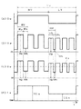
図1は、従来技術のアーク長揺動パルスアーク溶接の電流・電圧波形図である。同図(A)は切換周期信号Ttcの時間変化を示し、同図(B)は溶接電流Iwの時間変化を示し、同図(C)は溶接電圧Vwの時間変化を示し、同図(D)はアーク長Laの時間変化を示す。以下、同図を参照して説明する。
【0004】
同図(A)に示すように、切換周期信号Ttcは、予め定めたHighレベルの高アーク長期間HTと、予め定めたLowレベルの低アーク長期間LTとを切換周期Tc毎に繰り返す。これに応動して、同図(D)に示すように、アーク長Laは、上記の高アーク長期間HT中は高アーク長HLaとなり、上記の低アーク長期間LT中は低アーク長LLaとなる。
【0005】
▲1▼ 高アーク長期間HT
同図(B)に示すように、高ピーク期間HTp中は高ピーク電流HIpを通電し、高ベース期間HTb中は高ベース電流HIbを通電し、これらの通電を高パルス周期HTfとして高アーク長期間HT中繰り返して通電する。同様に、同図(C)に示すように、高ピーク期間HTp中は高ピーク電圧HVpが印加し、高ベース期間HTb中は高ベース電圧HVbが印加し、これらの印加を高アーク長期間HT中繰り返して行う。
【0006】
▲2▼ 低アーク長期間LT
同図(B)に示すように、低ピーク期間LTp中は低ピーク電流LIpを通電し、低ベース期間LTb中は低ベース電流LIbを通電し、これらの通電を低パルス周期LTfとして低アーク長期間LT中繰り返して通電する。同様に、同図(C)に示すように、低ピーク期間LTp中は低ピーク電圧LVpが印加し、低ベース期間LTb中は低ベース電圧LVbが印加し、これらの印加を低アーク長期間LT中繰り返して行う。
【0007】
上記の高ピーク電流HIpと高ピーク期間HTpとの組合せ及び上記の低ピーク電流LIpと低ピーク期間LTpとの組合せは、溶接ワイヤが1パルス1溶滴移行する範囲内で予め設定される。このピーク電流とピーク期間との組合せは、一般的にユニットパルス条件と呼ばれる。また、上記の高ベース電流HIb及び上記の低ベース電流LIbは、溶接ワイヤが溶融しないように数十A以下の低い値に予め設定される。同図(D)に示す高アーク長HLaと低アーク長Llaとの変化幅を数mm以上と大きくするためには、上記の高ピーク電流HIpと低ピーク電流LIpとの差及び高ピーク期間HTpと低ピーク期間LTpとの差を、1パルス1溶滴移行する範囲内で大きくなるように設定するのが通常である。これは、アーク長Laの変化幅が数mm以上の所定値よりも小さいと、前述したビード外観の波目模様のメリカリが少なくなり、美しさの度合いが下がるからである。さらに、前述した溶融池の攪拌作用によるブローホール発生数の削減効果も、同様に小さくなるからである。すなわち、本アーク長揺動パルスアーク溶接方法に特有の効果を得るためには、アーク長の揺動幅を数mm以上の所定値にする必要があり、そのためには上記のユニットパルス条件を大きく変化させる必要がある。溶接ワイヤに直径1.2mmのアルミニウム−マグネシウム合金ワイヤを使用し、溶接電流が100Aであるときの上記のユニットパルス条件の設定例を下記に示す。
(設定例1)
高ピーク電流HIp=360A,高ピーク期間HTp=2。0ms
低ピーク電流LIp=280A,低ピーク期間LTp=1.2ms
【0008】
また、同図(C)に示すように、溶接電圧Vwを大きな時定数で平滑して算出した切換周期Tc中の溶接電圧平均値が予め定めた電圧設定値Vsと略等しくなるようにフィードバック制御されて、操作量としての高パルス周期HTf又は低パルス周期LTfが制御される。これによって、切換周期Tc中の平均アーク長が制御される。溶接電圧Vwを大きな時定数で平滑する理由は、図2〜3で後述するように、アーク長とは比例関係にない種々の異常電圧が発生して溶接電圧Vwに重畳することがときどき生じる。この結果、異常電圧の影響によってアーク長の検出に誤差が生じ、アーク長制御が不安定になる。このランダムに発生する異常電圧の影響を抑制するために、溶接電圧Vwを大きな時定数で平滑する必要がある。したがって、従来技術では、平均アーク長を上記の溶接電圧平均値で制御すると共に、前述したように、高/低ピーク電流と高/低ピーク期間との組合せ(ユニットパルス条件)の設定値の差を大きくすることでアーク長の変化幅を大きくしている。
【0009】
上記においては、ピーク電流とピーク期間との組合せをユニットパルス条件として、このユニットパルス条件及びベース電流を予め設定し、パルス周期を制御する場合について説明した。ここで、ピーク電流とパルス周期との組合せをユニットパルス条件とし、このユニットパルス条件及びベース電流を予め設定し、ピーク期間を制御する場合も従来から行われている。この場合には、ピーク電流とパルス周期との組合せの設定値を大きく変化させることによって、アーク長の変化幅を大きくする。
【0010】
上述したように、従来技術では、溶接電圧Vwをフィードバックしてアーク長を制御する。しかし、溶接中には外乱となる種々のアーク現象がランダムに発生しており、これらのアーク現象に起因して溶接電圧Vwに異常電圧が重畳されることがある。本来、この異常電圧はアーク長とは何ら関係しない電圧であるために、異常電圧が重畳した溶接電圧Vwによってはアーク長を正確に検出することはできない。一般的に、上記の異常電圧の発生は、シールドガス中に酸化性成分が少ないほど顕著である。したがって、アルゴンガス、ヘリウムガス等の不活性ガスを主成分とするシールドガスを使用するパルスMIG溶接では、この異常電圧の発生頻度が高く、アーク長の誤検出の悪影響は大きくなる。以下、アルミニウム合金のパルスMIG溶接において、異常電圧が発生する2つの典型的な例について説明する。
【0011】
▲1▼ 微小短絡直後の異常電圧
図2は、ベース期間中に微小短絡が発生したときの電圧・電流波形図であり、同図(A)は溶接電圧Vwの時間変化を示し、同図(B)は溶接電流Iwの時間変化を示す。同図は、前述した図1の高パルス周期HTf及び低パルス周期LTfのどちらの期間中にも当てはまる。以下、同図を参照して説明する。
前述したように、パルスアーク溶接では、1回のピーク電流の通電によって1パルス1溶滴移行するようにピーク期間を設定するので、溶滴移行に伴って溶接ワイヤ先端部が長く伸びて溶滴と母材とが短時間接触(微小短絡)することが生じる。同図(A)に示すように、時刻t1において短絡が発生し短時間後の時刻t2において短絡が開放されると、その直後の時刻t2〜t3の間は、点線で示す通常値よりも非常に大きな値の異常電圧が重畳することがある。この理由は、時刻t1の短絡発生によってアークがいったん消滅し、時刻t2においてアークが再点弧する。この再点弧時には、陰極点は溶接ワイヤ直下の最短距離となる溶融池上に形成される。しかし、溶融池表面の酸化皮膜は通常既にクリーニングされているために、陰極点は酸化皮膜のない部分に形成されることになる。このために、陰極降下電圧値が非常に大きな値となり、異常電圧として重畳することになる。この陰極降下電圧値は、アーク長とは比例関係にないために、異常電圧が重畳した溶接電圧Vwによっては、アーク長を正しく検出することができない。この陰極降下電圧値は、母材の酸化皮膜のクリーニング状態、陰極点の形成位置等によって影響されるので、その値が小さくなり発生期間も短い場合もある。逆に、その値が大きくなり発生期間も長い場合もある。
【0012】
▲2▼ ベース期間中の陰極点の移動に伴う異常電圧
図3は、ベース期間中に陰極点が移動したときの電圧・電流波形図であり、同図(A)は溶接電圧Vwの時間変化を示し、同図(B)は溶接電流Iwの時間変化を示す。同図は、図1で前述した高パルス周期HTf及び低パルス周期LTfのどちらの期間中にも当てはまる。以下、同図を参照して説明する。
前述したように、ベース電流値は数十A程度と低い値であるために、アークの指向性が弱くなり、ベース期間中の陰極点は酸化皮膜を求めて移動しやすい。そして、陰極点が移動して新たに形成されるときに、母材表面の酸化皮膜の状態によって上記の陰極降下電圧値が変動することになり、溶接電圧Vwに異常電圧が重畳する場合が生じる。同図(A)に示すように、時刻t1〜t2の期間中に陰極点が移動すると、この期間中の溶接電圧Vwは変動して異常電圧となる。この異常電圧は、点線で示す通常値から大きく変動しており、かつアーク長とは関係しない値であるために、この異常電圧が重畳した溶接電圧Vwによっては、アーク長を正しく検出することはできない。
【0013】
上述したように、種々のアーク現象に伴ってアーク長とは関係のない異常電圧が発生すると、この異常電圧を含む溶接電圧Vwによっては、アーク長を正確に検出することができない。そこで、前述したように、ランダムに発生する異常電圧の悪影響を抑制するために、溶接電圧Vwを大きな時定数で平滑した溶接電圧平均値によって、平均アーク長を制御している。
【0014】
【発明が解決しようとする課題】
図4は、従来技術の課題を説明するための低アーク長期間LT及び高アーク長期間HT中の溶滴移行の状態を示す図である。同図(A)は低アーク長期間LT中の溶滴移行の状態及び溶接電流波形を示し、同図(B)は高アーク長期間HT中の溶滴移行の状態及び溶接電流波形を示す。前述したように、LIp<HIpであり、かつLTp<HTpである。また、前述したように、アーク長の変化幅を大きくするために、ピーク電流とピーク期間との組合せは、1パルス1溶滴移行の範囲内において大きく変化するように設定される。このために、通常、低ピーク電流LIpと低ピーク期間LTpとの組合せは、溶滴移行がピーク期間の終了時点の直前又は直後に行われるように、1パルス1溶滴移行の範囲の下限値近くに設定される。他方、高ピーク電流HIpと高ピーク期間HTpとの組合せは、アーク長の変動幅を大きくするために、1パルス1溶滴移行の範囲の上限値近くに設定される。以下、同図を参照して説明する。
【0015】
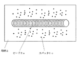
▲1▼ 低アーク長期間LT中の溶滴移行の状態
同図(A)に示すように、低ピーク期間LTp中の低ピーク電流LIpの通電によって、溶接ワイヤ1の先端部が溶融されて、溶滴1aが形成される。その後、低ピーク期間LTpの終了直後において、溶滴1aは離脱して母材へと落下し、溶接ワイヤ1の先端部には溶滴1aの一部が残留溶滴1bとして残る。このとき、溶滴1aは低ピーク期間LTp中に形成されて、低ピーク期間LTpの終了直後に移行するので、上記の残留溶滴1bはわずかな量となる。この結果、良好な溶滴移行状態となり、スパッタ、ヒューム等の発生量も非常に少ない。
【0016】
▲2▼ 高アーク長期間HT中の溶滴移行の状態
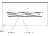
同図(B)に示すように、高ピーク電流HIp及び高ピーク期間HTpの組合せは、前述したように、上記の低アーク長期間時と比べて大きな値に設定される。このために、溶滴1aは、高ピーク期間HTpの半ばで移行することになり、溶滴移行後の残留溶滴1bが高ピーク電流HIpによって過熱されて大きくなる。そして、この残留溶滴1bは多数のスパッタ1c及びヒュームとなって飛散する。したがって、この期間中は、スパッタ1c及びヒュームが大量に発生することになり、ビード外観が悪くなる。このビード外観の一例を図5に示す。溶接条件は、直径1.2mmのアルミニウム−マグネシウム合金ワイヤを使用して、高ピーク電流HIp=360A、高ピーク期間HTP=2。0ms、低ピーク電流LIp=280A及び低ピーク期間LTP=1.2 msに設定し、溶接電流100AでパルスMIG溶接を行った場合である。同図から明らかなように、ビード2aは波目模様が形成されているが、母材2上には大量のスパッタ1cが付着している。
【0017】
上述したように、従来技術では、アーク長の変化幅を大きくするために、ユニットパルス条件を大きく変化させなければならないために、どうしても高アーク長期間中にスパッタ、ヒューム等が多く発生することになる。
【0018】
そこで、本発明では、アーク長の変化幅を大きくすることができ、かつスパッタ、ヒューム等の発生量を減少させることができるアーク長揺動パルスアーク溶接制御方法を提供する。
【0019】
【課題を解決するための手段】
第1の発明は、図6〜7に示すように、
溶接ワイヤを定速で送給し、ピーク期間Tp中のピーク電流Ipの通電とベース期間Tb中のベース電流Ibの通電とをパルス周期Tfとして繰り返して通電すると共に、前記ピーク期間Tp中のピーク電圧値Vpがピーク電圧設定値Vpsと略等しくなるように操作量として前記パルス周期Tf又は前記ピーク期間Tpを変化させてアーク長を制御するパルスアーク溶接において、
前記操作量がパルス周期Tfであるときは前記ピーク期間Tp及び前記ピーク電流Ipを、前記操作量がピーク期間Tpであるときは前記パルス周期Tf及び前記ピーク電流Ipを一定値としたままで、
前記ピーク電圧設定値Vpsを予め定めた切換周期Tcで変化させることによってアーク長を周期的に所定幅で揺動させることを特徴とするアーク長揺動パルスアーク溶接制御方法である。
【0021】
第2の発明は、図10に示すように、
前記ピーク電圧値Vpが、前記ピーク期間Tpの開始時の電圧が過渡的に変動する過渡ピーク期間Tpaを除いた定常ピーク期間Tpb中の定常ピーク電圧値Vpaであることを特徴とする請求項1記載のアーク長揺動パルスアーク溶接制御方法である。
【0022】
【発明の実施の形態】
以下に、本発明の実施の形態として、実施例1〜3について図面を参照して説明する。
[実施例1]
アーク長揺動パルスアーク溶接方法において、ビード外観に美しい波目模様を形成する効果、溶融池攪拌によるブローホール発生を抑制する効果等の特有の効果は、アーク長を周期的に揺動させてアークの広がり、アーク力を変化させることによって生じる。そこで、実施例1の発明では、ユニットパルス条件(ピーク電流Ipとピーク期間Tpとの組合せ)を高アーク長期間HT及び低アーク長期間LTで同一値に設定し、アーク長をピーク期間Tp中のピーク電圧Vpによって検出し、その目標値であるピーク電圧設定値Vpsを高アーク長期間HTと低アーク長期間LTとで切り換えることによってアーク長を周期的に揺動させる方法である。上記のユニットパルス条件は、溶滴移行がピーク期間Tpの終了時点の直前又は直後に行われるように予め設定する。このことで、溶滴移行後の残留溶滴への過熱を防止し、スパッタ、ヒューム等の発生を抑制する。また、アーク長をピーク電圧Vpによって検出する理由は、以下のとおりである。すなわち、ピーク期間Tp中は数百Aの高いピーク電流Ipが通電するために、アークの指向性が非常に高くなる。このために、ピーク期間Tp中のアークは、溶接ワイヤの送給方向に形成されて、かつ、指向性が高いためにその陰極点は酸化皮膜を求めて移動することができない。この結果、ピーク期間Tp中のアーク形状はほぼ一定になるので、アーク長とピーク電圧Vpとは正確な比例関係になる。さらには、ピーク期間Tp中は、図2で前述した微小短絡はほとんど発生しない。また、ピーク期間Tp中は、図3で前述した陰極点の移動もほぼないために、異常電圧の発生頻度は少なくなり、異常電圧によるピーク電圧Vpへの影響は小さい。このために、ピーク電圧Vpは、前述した溶接電圧平均値の算出のときのように異常電圧の影響を抑制する目的で大きな時定数で平滑する必要がないので、平滑の時定数を小さくすることができ、アーク長検出の応答性を速くすることができる。すなわち、ピーク電圧Vpによるアーク長検出では、パルス周期毎のアーク長の変化を検出することができる。したがって、高アーク長期間HT中の高ピーク電圧設定値HVpsと、低アーク長期間LT中の低ピーク電圧設定値LVpsとを予め設定し、周期的に切り換えることによってアーク長を揺動させることができる。以下、図面を参照して説明する。
【0023】
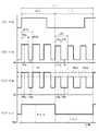
図6は、実施例1の発明のアーク長揺動パルスアーク溶接の電流・電圧波形図である。同図(A)は切換周期信号Ttcの時間変化を示し、同図(B)は溶接電流Iwの時間変化を示し、同図(C)は溶接電圧Vwの時間変化を示し、同図(D)はアーク長Laの時間変化を示す。以下、同図を参照して説明する。
【0024】
同図(A)に示すように、切換周期信号Ttcは、予め定めたHighレベルの高アーク長期間HTと、予め定めたLowレベルの低アーク長期間LTとを切換周期Tc毎に繰り返す。これに応動して、同図(D)に示すように、アーク長Laは、上記の高アーク長期間HT中は高アーク長HLaとなり、上記の低アーク長期間LT中は低アーク長LLaとなる。
【0025】
▲1▼ 高アーク長期間HT
同図(B)に示すように、ピーク期間Tp中はピーク電流Ipを通電し、高ベース期間HTb中はベース電流Ibを通電し、これらの通電を高パルス周期HTfとして高アーク長期間HT中繰り返して通電する。同様に、同図(C)に示すように、ピーク電圧が予め定めた高ピーク電圧設定値HVpsと略等しくなるようにフィードバック制御されて、操作量として上記のパルス周期が制御される。したがって、パルス周期はフィードバック制御によって刻々変化して、後述する低アーク長期間LTとは異なる高パルス周期HTfとなり、ピーク期間Tpは一定であるので、ベース期間も刻々変化して上記の高ベース期間HTbとなる。また、同図(C)に示すように、ピーク電圧は上記の高ピーク電圧設定値HVpsと略等しい値の高ピーク電圧値HVpとなり、ベース電圧は高ベース電圧値HVbとなる。
【0026】
▲2▼ 低アーク長期間LT
同図(B)に示すように、上記▲1▼項と同一値のピーク期間Tp中はピーク電流Ipを通電し、低ベース期間LTb中はベース電流Ibを通電し、これらの通電を低パルス周期LTfとして低アーク長期間LT中繰り返して通電する。同様に、同図(C)に示すように、ピーク電圧が予め定めた低ピーク電圧設定値LVpsと略等しくなるようにフィードバック制御されて、操作量として上記のパルス周期が制御される。したがって、パルス周期はフィードバック制御によって刻々変化し、前述した高アーク長期間HTとは異なる低パルス周期LTfとなり、ピーク期間Tpは一定であるので、ベース期間も刻々変化して上記の低ベース期間LTbとなる。また、同図(C)に示すように、ピーク電圧は上記の低ピーク電圧設定値LVpsと略等しい値の低ピーク電圧値LVpとなり、ベース電圧は低ベース電圧値LVbとなる。
【0027】
上述したように、操作量がパルス周期であるときには、ユニットパルス条件のピーク電流とピーク期間との組合せを、溶滴移行がピーク期間の終了時点の直前又は直後に行われるように予め設定する。他方、操作量がピーク期間であるときには、ユニットパルス条件のピーク電流とパルス周期との組合せを、溶滴移行がピーク期間の終了時点の直前又は直後に行われるように予め設定する。
【0028】
以上のように、実施例1の発明では、ピーク電圧によってアーク長を検出し、所定値の高アーク長HLaに対応する高ピーク電圧設定値HVpsと、所定値の低アーク長LLaに対応する低ピーク電圧設定値LVpsとを、切換周期Tc毎に切り換えることによって、アーク長を揺動させることができる。
【0029】
図7は、上述した実施例1の発明を実施するための溶接電源装置のブロック図である。以下、同図を参照して各回路ブロックについて説明する。
出力制御回路INVは、3相200V等の商用電源を入力として、後述する電流誤差増幅信号Eiに従って、インバータ制御、サイリスタ位相制御等の出力制御を行い、溶接に適した溶接電圧Vw及び溶接電流Iwを出力する。溶接ワイヤ1は、ワイヤ送給装置の送給ロール5の回転によって送給されて、母材2との間でアーク3が発生して、溶接が行われる。
【0030】
電圧検出回路VDは、溶接電圧Vwを検出して、電圧検出信号Vdを出力する。ピーク電圧検出回路DVPは、上記の電圧検出信号Vdを入力として、ピーク電圧検出信号DVpを出力する。切換周期信号生成回路TTCは、予め定めた高アーク長期間HT中はHighレベルとなり、予め定めた低アーク長期間LT中はLowレベルとなる切換周期信号Ttcを出力する。高ピーク電圧設定回路HVPSは、予め定めた高ピーク電圧設定信号HVpsを出力する。低ピーク電圧設定回路LVPSは、予め定めた低ピーク電圧設定信号LVpsを出力する。電圧設定信号切換回路SWVは、上記の切換周期信号TtcがHighレベル(高アーク長期間HT)のときにはa側に切り換わり上記の高ピーク電圧設定信号HVpsをピーク電圧設定信号Vpsとして出力し、Lowレベル(低アーク長期間LT)のときにはb側に切り換わり上記の低ピーク電圧設定信号LVpsをピーク電圧設定信号Vpsとして出力する。
【0031】
電圧誤差増幅回路EVは、上記のピーク電圧検出信号DVpと上記のピーク電圧設定信号Vpsとの誤差を増幅して、電圧誤差増幅信号Evを出力する。電圧周波数変換回路V/Fは、上記の電圧誤差増幅信号Evに反比例した周期毎に短時間Highレベルとなるパルス周期信号Ttfを出力する。ピーク期間設定回路TPSは、予め定めたピーク期間設定信号Tpsを出力する。ピーク期間タイマ回路TTPは、上記のパルス周期信号TtfがHighレベルに変化した時点から上記のピーク期間設定信号Ttpによって定まる期間だけHighレベルとなるピーク期間信号Ttpを出力する。
【0032】
ピーク電流設定回路IPSは、予め定めたピーク電流設定信号Ipsを出力する。ベース電流設定回路IBSは、予め定めたベース電流設定信号Ibsを出力する。電流制御設定回路ISCは、上記のピーク期間信号TtpがHighレベル(ピーク期間)のときには上記のピーク電流設定信号Ipsを電流制御設定信号Iscとして出力し、Lowレベル(ベース期間)のときには上記のベース電流設定信号Ibsを電流制御設定信号Iscとして出力する。電流検出回路IDは、溶接電流Iwを検出して、電流検出信号Idを出力する。電流誤差増幅回路EIは、上記の電流検出信号Idと上記の電流制御設定信号Iscとの誤差を増幅して、電流誤差増幅信号Eiを出力する。上述した溶接電源装置によって、切換周期信号Ttc毎にアーク長を揺動させてパルスアーク溶接を行うことができる。
【0033】
[実施例2]
実施例2の発明では、上述した実施例1の発明において、高アーク長期間HTと低アーク長期間LTとで、ユニットパルス条件(ピーク電流Ipとピーク期間Tpとの組合せ又はピーク電流Ipとパルス周期Tfとの組合せ)を、溶滴移行がピーク期間の終了時点の直前又は直後に行われる範囲内で切り換える方法である。ユニットパルス条件を切り換える理由は、以下のとおりである。すなわち、ピーク電流及びピーク期間が一定値であるときは、ピーク電圧設定値Vpsに反比例してパルス周期が定まる。したがって、ピーク電圧設定値Vpsが大きな値に設定されると、それに対応してアーク長を長くするために溶接電流平均値が大きくなる。このために、パルス周期は非常に短くなるが、パルス周期があまり短くなるとフィードバック制御の調整範囲の限界値に近くなり、外乱に対してアーク長制御を行うことができず、溶接状態が不安定になる。このときに、ピーク電流又はピーク期間の少なくとも1つ以上を大きくすると、パルス周期は長くなるので、上記の問題が解消されて溶接状態は安定になる。逆に、ピーク電圧設定値Vpsが小さい値に設定されると、それに対応してアーク長を短くするために溶接電流平均値は小さくなる、このために、パルス周期は非常に長くなり、ビード外観が悪くなる。このときに、ピーク電流又はピーク期間の少なくとも1つ以上を小さくすると、パルス周期が短くなるので、ビード外観は良好になる。このように、ユニットパルス条件を切換周期信号Ttcに応動して変化させることによって、パルス周期を所定範囲内に制限することができ、この結果、溶接状態を常に安定に維持することができる。
【0034】
図8は、実施例2の発明のアーク長揺動パルスアーク溶接の電流・電圧波形図である。同図(A)は切換周期信号Ttcの時間変化を示し、同図(B)は溶接電流Iwの時間変化を示し、同図(C)は溶接電圧Vwの時間変化を示し、同図(D)はアーク長Laの時間変化を示す。同図において、低アーク長期間LTの低ピーク電流LIp及び低ピーク期間LTpは、前述した図6のピーク電流Ip及びピーク期間Tpと同一値に設定されている。他方、高アーク長期間HTの高ピーク電流HIp及び高ピーク期間HTpは、溶滴移行がピーク期間の終了時点の直前又は直後に行われる範囲内において図6のときの値よりも大きい値に設定されたときである。すなわち、HIP>LIp=Ipであり、HTp>LTp=Tpである。以下、同図を参照して説明する。
【0035】
▲1▼ 高アーク長期間HT
同図(B)に示すように、高ピーク期間HTp中は高ピーク電流HIpを通電し、高ベース期間HTb中はベース電流Ibを通電し、これらの通電を高パルス周期HTfとして高アーク長期間HT中繰り返して通電する。同様に、同図(C)に示すように、ピーク電圧が前述した図6と同一値の高ピーク電圧設定値HVpsと略等しくなるようにフィードバック制御されて、操作量として上記のパルス周期が制御される。前述したように、HIp>IpでありかつHTp>Tpであるので、パルス周期HTf2>HTfとなり、パルス周期が短くなりすぎて溶接状態が不安定になることを抑制することができる。
【0036】
▲2▼ 低アーク長期間LT
同図(B)に示すように、低ピーク期間LTp中は低ピーク電流LIpを通電し、低ベース期間LTb中はベース電流Ibを通電し、これらの通電を低パルス周期LTfとして低アーク長期間LT中繰り返して通電する。同様に、同図(C)に示すように、ピーク電圧が前述した図6のときと同一値の低ピーク電圧設定値LVpsと略等しくなるようにフィードバック制御されて、操作量として上記のパルス周期が制御される。前述したように、LIp=IpでありかつLTp=Tpであるので、低パルス周期LTfは図6のときと同一値となる。
【0037】
上記においては、ユニットパルス条件がピーク電流とピーク期間との組合せときであるが、ユニットパルス条件がピーク電流とパルス周期との組合せであるときには、操作量はピーク期間となり、この場合でも上記と同様である。すなわち、ピーク電圧設定値が大きいとピーク期間が長くなりすぎて溶接状態が不安定になりやすく、逆にピーク電圧設定値が小さいとピーク期間が短くなりすぎて上記と同様に溶接状態が不安定になりやすい。このようなときには、高アーク長期間と低アーク長期間とで、ユニットパルス条件を異なった値に設定することで、ピーク期間を所定範囲内に制限することができ、良好な溶接状態を維持することができる。
【0038】
図9は、上述した実施例2の発明を実施するための溶接電源装置のブロック図である。同図において、前述した図7と同一の回路ブロックには同一符号を付してそれらの説明は省略する。以下、図7とは異なる点線で示す回路ブロックについて、図面を参照して説明する。
【0039】
高ピーク期間設定回路HTPは、予め定めた高ピーク期間設定信号HTpを出力する。低ピーク期間設定回路LTPは、予め定めた低ピーク期間設定信号LTpを出力する。期間設定信号切換回路SWTは、切換周期信号TtcがHighレベル(高アーク長期間)のときにはa側に切り換わり上記の高ピーク期間設定信号HTpをピーク期間設定信号Tpsとして出力し、Lowレベル(低アーク長期間)のときには上記の低ピーク期間設定信号LTpをピーク期間設定信号Tpsとして出力する。
【0040】
高ピーク電流設定回路HIPは、予め定めた高ピーク電流設定信号HIpを出力する。低ピーク電流設定回路LIPは、予め定めた低ピーク電流設定信号LIpを出力する。電流設定信号切換回路SWIは、切換周期信号TtcがHighレベル(高アーク長期間)のときにはa側に切り換わり上記の高ピーク電流設定信号HIpをピーク電流設定信号Ipsとして出力し、Lowレベル(低アーク長期間)のときにはb側に切り換わり上記の低ピーク電流設定信号LIpをピーク電流設定信号Ipsとして出力する。
【0041】
[実施例3]
実施例3の発明は、実施例1又は2の発明において、ピーク電圧検出信号DVpが、ピーク期間の開始時の電圧が過渡的に変動する過渡ピーク期間を除いた定常ピーク期間中の定常ピーク電圧検出信号Vpaであるアーク長揺動パルスアーク溶接制御方法である。以下、図面を参照して実施例3の発明について説明する。
【0042】
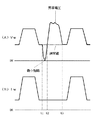
図10は、実施例3における定常ピーク電圧値の算出方法を説明するためのピーク電圧波形図である。同図は、高アーク長期間及び低アーク長期間の両方のピーク期間中のピーク電圧波形である。同図に示すように、時刻t1のピーク期間Tpの開始時において、過渡ピーク期間Tpa中のピーク電圧は、アークの発生状態に応じて曲線Y1〜Y3のように大きく変動する。そして、この過渡ピーク期間Tpaが経過して定常ピーク期間Tpbに入ると、アーク発生状態は安定するので、このときのピーク電圧値は安定した略定常値(以下、定常ピーク電圧値Vpaという)になり、アーク長と正確に比例する。したがって、この定常ピーク電圧値Vpaによってアーク長を正確に検出して、アーク長を揺動させれば、より安定したアーク長揺動パルスアーク溶接を行うことができる。
【0043】
上記の定常ピーク電圧値Vpaとしては、以下のような算出値を使用することができる。
▲1▼ 特定時点の定常ピーク電圧瞬時値Vpc
同図に示すように、ピーク期間Tpの開始時点から予め定めた遅延時間Tpcが経過した時点の定常ピーク電圧瞬時値Vpcを、定常ピーク電圧値Vpaとして使用することができる。上記の遅延時間Tpcは、過渡ピーク期間Tpaが経過した後から、曲線Y4に示す溶滴移行時の陽極点の移動に伴う電圧変動が発生する前までの期間中の特定時点になるように、予め設定される。例えば、前述したピーク期間Tpの真ん中の時点に設定することが考えられる。
【0044】
▲2▼ 所定期間中の定常ピーク電圧平均値Vpd
上記▲1▼項は瞬時値であるが、検出誤差を減少させるために、上記の遅延時間Tpc経過後から所定の平均化期間Tpd中の定常ピーク電圧の平均値Vpdを、定常ピーク電圧値Vpaとして使用することができる。
【0045】
▲3▼ 定常ピーク期間中の定常ピーク電圧平均値Vpb
上記▲2▼項においてピーク電圧を平均化する期間を、定常ピーク期間Tpbの全期間中とするのが、定常ピーク期間中の定常ピーク電圧平均値Vpbである。
【0046】
▲4▼ 上記▲1▼〜▲3▼項の移動平均値
第n回目のピーク期間Tp(n)中の上記▲1▼項の定常ピーク電圧瞬時値をVpc(n)とし、今周期から前の所定周期m回にわたる移動平均値Vpcrは、下式となる。
Vpcr=(Vpc(n)+Vpc(n-1)+…+Vpc(n-m+1))/m
上式では、各周期の定常ピーク電圧瞬時値Vpcは均等の重みで平均化しているが、今周期に近い周期の値の重みを重くする重み付け移動平均値であってもよい。このように移動平均値を算出して定常ピーク電圧値Vpaとする理由は、以下のとおりである。すなわち、定常ピーク期間Tpb中は、陰極点はほぼ移動することなく形成されていてが、溶融池の状態、溶滴の状態等は毎周期ごとに少しは変動しているために、アーク長も変動することになる。この変動を平均化してより正確なアーク長を検出するために移動平均値を算出している。また、上記▲2▼項及び▲3▼項の定常ピーク電圧平均値Vpd及びVpbの過去所定周期にわたる移動平均値についても、上記と同様にして算出することができる。
【0047】
上述した実施例3の発明を実施するための溶接電源装置の構成は、前述した図7及び9におけるピーク電圧検出回路DVPによって、上記の定常ピーク電圧検出信号Vpaを算出するように変更する以外は同一である。
【0048】
[効果]
以下に、本発明の効果について図面を参照して説明する。
図11は、前述した図5に対応する本発明のビード外観図である。溶接条件は、前述したように、直径1.2mmのアルミニウム−マグネシウム合金ワイヤを使用して、高ピーク電流HIp=320A、高ピーク期間HTp=1.6ms、低ピーク電流LIp=280A、低ピーク期間LTp=1.2 ms、高ピーク電圧設定値HVps=22V、低ピーク電圧設定値LVps=26V及び溶接電流=100Aに設定し、アルミニウム合金のパルスMIG溶接の場合である。このときの高アーク長HLa=8mmとなり、低アーク長LLa=3mmとなった。同図から明らかなように、ビード2aには美しい波目模様が形成されており、かつ、図5のときとは異なり母材2上にはほとんどスパッタ1cが付着していない。また、溶接中のヒュームの発生量も大きく減少した。
【0049】
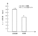
図12は、溶接中のヒューム発生量の比較図である。溶接条件は、従来技術のときには図5の条件に設定し、本発明のときには図11の条件に設定して、アーク長揺動パルスMIG溶接を行った場合である。ヒュームの測定値は、溶接ワイヤ1g当りのヒューム発生量に換算した。同図から明らかなように、従来技術ではヒューム発生量は14mg/gであった。これに対して、本発明では、ヒューム発生量は9mg/gへと大きく減少した。
【0050】
【発明の効果】
本発明のアーク長揺動パルスアーク溶接制御方法では、ユニットパルス条件を溶滴移行がピーク期間の終了時点の直前又は直後に行われる範囲に設定し、ピーク電圧によってアーク長を正確に検出し、その目標値であるピーク電圧設定値を周期的に変化させることによってアーク長を所定幅で揺動させることができるので、スパッタ、ヒューム等の発生量を大幅に減少させた上に、本溶接方法の特徴である波目模様のビード外観の形成、溶融池攪拌によるブローホール発生数の削減等の効果も同時に有している。
さらに、実施例2の発明では、ユニットパルス条件を高アーク長期間と低アーク長期間とで変化させることによって、パルス周期又はピーク期間が短く又は長くなりすぎて溶接状態が不安定になることを抑制することができる。したがって、アーク長の揺動幅を大きく設定しても、溶接状態は常に安定しており、良好な溶接品質を得ることができる。
さらに、実施例3の発明では、定常ピーク電圧値によってアーク長を正確に検出することができるので、アーク長の揺動制御がさらに安定になり、溶接品質もさらに向上する。
【図面の簡単な説明】
【図1】従来技術のアーク長揺動パルスアーク溶接の電流・電圧波形図
【図2】従来技術での微小短絡直後の異常電圧波形図
【図3】従来技術でのベース期間中の異常電圧波形図
【図4】従来技術の課題を示す溶滴移行の状態図
【図5】従来技術のビード外観図
【図6】実施例1のアーク長揺動パルスアーク溶接の電流・電圧波形図
【図7】実施例1の溶接電源装置のブロック図
【図8】実施例2のアーク長揺動パルスアーク溶接の電流・電圧波形図
【図9】実施例2の溶接電源装置のブロック図
【図10】実施例3の定常ピーク電圧値の算出方法を示すピーク電圧波形図
【図11】本発明の効果を示すビード外観図
【図12】本発明の効果を示すヒューム発生量の比較図
【符号の説明】
1 溶接ワイヤ
1a 溶滴
1b 残留溶滴
1c スパッタ
2 母材
2a ビード
5 送給ロール
DVP ピーク電圧検出回路
DVp ピーク電圧検出信号
EI 電流誤差増幅回路
Ei 電流誤差増幅信号
EV 電圧誤差増幅回路
Ev 電圧誤差増幅信号
HIb 高ベース電流
HIP 高ピーク電流設定回路
HIp 高ピーク電流(設定信号)
HLa 高アーク長
HT 高アーク長期間
HTb 高ベース期間
HTf 高パルス周期
HTP 高ピーク期間設定回路
HTp 高ピーク期間(設定信号)
HVb 高ベース電圧
HVp 高ピーク電圧
HVPS 高ピーク電圧設定回路
HVps 高ピーク電圧設定(値/信号
Ib ベース電流
IBS ベース電流設定回路
Ibs ベース電流設定信号
ID 電流検出回路
Id 電流検出信号
INV 出力制御回路
Ip ピーク電流
IPS ピーク電流設定回路
Ips ピーク電流設定信号
ISC 電流制御設定回路
Isc 電流制御設定信号
Iw 溶接電流
La アーク長
LIb 低ベース電流
LIP 低ピーク電流設定回路
LIp 低ピーク電流(設定信号)
LLa 低アーク長
LT 低アーク長期間
LTb 低ベース期間
LTf 低パルス周期
LTP 低ピーク期間設定回路
LTp 低ピーク期間(設定信号)
LVb 低ベース電圧
LVp 低ピーク電圧
LVPS 低ピーク電圧設定回路
LVps 低ピーク電圧設定(値/信号)
SWI 電流設定信号切換回路
SWT 期間設定信号切換回路
SWV 電圧設定信号切換回路
Tc 切換周期
Tp ピーク期間
Tpa 過渡ピーク期間
Tpb 定常ピーク期間
Tpc 遅延時間
Tpd 平均化期間
TPS ピーク期間設定回路
Tps ピーク期間設定信号
TTC 切換周期信号生成回路
Ttc 切換周期信号
Ttf パルス周期信号
TTP ピーク期間タイマ回路
Ttp ピーク期間信号
V/F 電圧周波数変換回路
VD 電圧検出回路
Vd 電圧検出信号
Vpa 定常ピーク電圧値
Vpb、Vpd 定常ピーク電圧平均値
Vpc 定常ピーク電圧瞬時値
Vpcr 定常ピーク電圧移動平均値
Vps ピーク電圧設定信号
Vs 電圧設定値
Vw 溶接電圧
Y1〜Y4 電圧変動曲線[0001]
BACKGROUND OF THE INVENTION
The present invention relates to an arc length control method of consumable electrode type pulse arc welding in which the arc length is periodically oscillated.
[0002]
[Prior art]
In consumable electrode type pulse arc welding in which the energization of the peak current Ip during the peak period Tp and the energization of the base current Ib during the base period Tb are repeated, the peak current Ip and the peak period Tp are set to a predetermined low level. 2. Description of the Related Art Conventionally, a welding method for changing the arc length to high and low by changing the frequency (several Hz to several tens of Hz) every switching cycle Tc has been performed. In this welding method, a bead appearance having a beautiful wave pattern can be obtained by changing the spread of the arc by swinging the arc length, and therefore, this welding method is used for welding a motorcycle frame in which appearance is important. Furthermore, in this welding method, it is possible to suppress the occurrence of welding defects such as blow holes by stirring the molten pool by changing the arc force by swinging the arc length. Hereinafter, this arc length fluctuation pulse arc welding method as a prior art will be described with reference to the drawings.
[0003]
FIG. 1 is a current / voltage waveform diagram of arc length fluctuation pulse arc welding of the prior art. (A) shows the time change of the switching cycle signal Ttc, (B) shows the time change of the welding current Iw, (C) shows the time change of the welding voltage Vw, (D) ) Indicates a change with time in the arc length La. Hereinafter, a description will be given with reference to FIG.
[0004]
As shown in FIG. 5A, the switching cycle signal Ttc repeats a predetermined high-level high arc long-term HT and a predetermined low-level low arc long-term LT every switching cycle Tc. In response to this, as shown in FIG. 4D, the arc length La becomes the high arc length HLa during the high arc long period HT, and the low arc length LLa during the low arc long period LT. Become.
[0005]
▲ 1 ▼ High arc long term HT
As shown in FIG. 5B, a high peak current HIp is applied during the high peak period HTp, a high base current HIb is applied during the high base period HTb, and the high arc length is set as a high pulse period HTf. Energize repeatedly during the period HT. Similarly, as shown in FIG. 5C, the high peak voltage HVp is applied during the high peak period HTp, the high base voltage HVb is applied during the high base period HTb, and these applications are applied for the high arc long period HT. Repeat repeatedly.
[0006]
(2) Low arc long-term LT
As shown in FIG. 5B, a low peak current LIp is applied during the low peak period LTp, and a low base current LIb is applied during the low base period LTb. Energization is repeated during the period LT. Similarly, as shown in FIG. 6C, the low peak voltage LVp is applied during the low peak period LTp, the low base voltage LVb is applied during the low base period LTb, and these applications are applied for the low arc long period LT. Repeat repeatedly.
[0007]
The combination of the high peak current HIp and the high peak period HTp and the combination of the low peak current LIp and the low peak period LTp are set in advance within a range in which the welding wire transfers one droplet per droplet. This combination of peak current and peak period is generally called unit pulse condition. The high base current HIb and the low base current LIb are set in advance to low values of several tens of A or less so that the welding wire does not melt. In order to increase the change width between the high arc length HLa and the low arc length Lla shown in FIG. 4D to several mm or more, the difference between the high peak current HIp and the low peak current LIp and the high peak period HTp are described. Usually, the difference between the low peak period LTp and the low peak period LTp is set so as to increase within the range of transfer of one pulse per droplet. This is because if the change width of the arc length La is smaller than a predetermined value of several mm or more, the wavy pattern of the bead appearance described above decreases, and the degree of beauty decreases. Furthermore, the effect of reducing the number of blowholes generated by the above-described stirring action of the molten pool is similarly reduced. That is, in order to obtain an effect specific to the arc length fluctuation pulse arc welding method, it is necessary to set the fluctuation width of the arc length to a predetermined value of several mm or more. Need to change. An example of setting the above unit pulse conditions when an aluminum-magnesium alloy wire having a diameter of 1.2 mm is used as the welding wire and the welding current is 100 A is shown below.
(Setting example 1)
High peak current HIp = 360 A, high peak period HTp = 2, 0 ms
Low peak current LIp = 280 A, low peak period LTp = 1.2 ms
[0008]
Further, as shown in FIG. 5C, feedback control is performed so that the welding voltage average value during the switching period Tc calculated by smoothing the welding voltage Vw with a large time constant becomes substantially equal to the predetermined voltage setting value Vs. Thus, the high pulse period HTf or the low pulse period LTf as the operation amount is controlled. This controls the average arc length during the switching period Tc. The reason why the welding voltage Vw is smoothed with a large time constant is that, as will be described later with reference to FIGS. 2 to 3, various abnormal voltages that are not proportional to the arc length are sometimes generated and superimposed on the welding voltage Vw. As a result, an error occurs in the detection of the arc length due to the influence of the abnormal voltage, and the arc length control becomes unstable. In order to suppress the influence of the randomly generated abnormal voltage, it is necessary to smooth the welding voltage Vw with a large time constant. Therefore, in the prior art, the average arc length is controlled by the above-mentioned welding voltage average value, and as described above, the difference between the set values of the combination of the high / low peak current and the high / low peak period (unit pulse condition). The change width of the arc length is increased by increasing.
[0009]
In the above description, the case where the combination of the peak current and the peak period is set as the unit pulse condition, the unit pulse condition and the base current are set in advance, and the pulse period is controlled has been described. Here, a combination of a peak current and a pulse period is used as a unit pulse condition, and the unit pulse condition and base current are set in advance to control the peak period. In this case, the change width of the arc length is increased by greatly changing the set value of the combination of the peak current and the pulse period.
[0010]
As described above, in the prior art, the arc length is controlled by feeding back the welding voltage Vw. However, various arc phenomena that cause disturbances are randomly generated during welding, and an abnormal voltage may be superimposed on the welding voltage Vw due to these arc phenomena. Originally, the abnormal voltage is a voltage that has nothing to do with the arc length, and therefore the arc length cannot be accurately detected by the welding voltage Vw on which the abnormal voltage is superimposed. In general, the occurrence of the abnormal voltage is more remarkable as the oxidizing component is smaller in the shield gas. Therefore, in pulsed MIG welding using a shield gas whose main component is an inert gas such as argon gas or helium gas, the frequency of occurrence of this abnormal voltage is high, and the adverse effect of false detection of the arc length is increased. Hereinafter, two typical examples in which an abnormal voltage is generated in pulsed MIG welding of an aluminum alloy will be described.
[0011]
(1) Abnormal voltage immediately after a short circuit
FIG. 2 is a voltage / current waveform diagram when a micro short circuit occurs during the base period. FIG. 2 (A) shows the time change of the welding voltage Vw, and FIG. 2 (B) shows the time change of the welding current Iw. Indicates. This figure applies to both the high pulse period HTf and the low pulse period LTf of FIG. 1 described above. Hereinafter, a description will be given with reference to FIG.
As described above, in the pulse arc welding, the peak period is set so that one pulse and one droplet transfer by energization of one peak current. And a base material contact for a short time (micro short circuit). As shown in FIG. 5A, when a short circuit occurs at time t1 and the short circuit is opened at a short time t2, the time between t2 and t3 immediately after that is much higher than the normal value indicated by the dotted line. A large value of abnormal voltage may be superimposed on the. This is because the arc once disappears due to the occurrence of a short circuit at time t1, and the arc is re-ignited at time t2. During this re-ignition, the cathode spot is formed on the molten pool that is the shortest distance directly below the welding wire. However, since the oxide film on the surface of the molten pool is usually already cleaned, the cathode spot is formed in a portion without the oxide film. For this reason, the cathode fall voltage value becomes a very large value and is superimposed as an abnormal voltage. Since this cathode fall voltage value is not proportional to the arc length, the arc length cannot be detected correctly depending on the welding voltage Vw on which the abnormal voltage is superimposed. Since this cathode fall voltage value is influenced by the cleaning state of the oxide film of the base material, the position where the cathode spot is formed, etc., the value may become small and the generation period may be short. Conversely, the value may increase and the generation period may be long.
[0012]
(2) Abnormal voltage accompanying the movement of the cathode spot during the base period
FIG. 3 is a voltage / current waveform diagram when the cathode spot moves during the base period. FIG. 3 (A) shows the time change of the welding voltage Vw, and FIG. 3 (B) shows the time change of the welding current Iw. Indicates. This figure applies to both the high pulse period HTf and the low pulse period LTf described above with reference to FIG. Hereinafter, a description will be given with reference to FIG.
As described above, since the base current value is as low as about several tens of A, the directivity of the arc becomes weak, and the cathode spot during the base period tends to move in search of the oxide film. When the cathode spot moves and is newly formed, the cathode fall voltage value fluctuates depending on the state of the oxide film on the surface of the base material, and an abnormal voltage may be superimposed on the welding voltage Vw. . As shown in FIG. 5A, when the cathode spot moves during the period from time t1 to time t2, the welding voltage Vw during this period varies and becomes an abnormal voltage. Since this abnormal voltage greatly varies from the normal value indicated by the dotted line and is not related to the arc length, the arc length cannot be detected correctly depending on the welding voltage Vw on which the abnormal voltage is superimposed. Can not.
[0013]
As described above, when an abnormal voltage unrelated to the arc length is generated with various arc phenomena, the arc length cannot be accurately detected depending on the welding voltage Vw including the abnormal voltage. Therefore, as described above, the average arc length is controlled by the welding voltage average value obtained by smoothing the welding voltage Vw with a large time constant in order to suppress the adverse effect of the abnormal voltage generated randomly.
[0014]
[Problems to be solved by the invention]
FIG. 4 is a diagram showing a state of droplet transfer during the low arc long-term LT and the high arc long-term HT for explaining the problems of the prior art. FIG. 5A shows the state of droplet transfer and welding current waveform during the low arc long-term LT, and FIG. 5B shows the state of droplet transfer and welding current waveform during the high arc long-term HT. As described above, LIp <HIp and LTp <HTp. Further, as described above, in order to increase the change width of the arc length, the combination of the peak current and the peak period is set so as to change greatly within the range of one pulse per droplet transfer. For this reason, the combination of the low peak current LIp and the low peak period LTp is usually the lower limit of the range of 1
[0015]
(1) Droplet transfer state during low arc long-term LT
As shown in FIG. 5A, the tip of the
[0016]
(2) State of droplet transfer during high arc long-term HT
As shown in FIG. 5B, the combination of the high peak current HIp and the high peak period HTp is set to a larger value as compared with the low arc long period as described above. For this reason, the droplet 1a moves in the middle of the high peak period HTp, and the residual droplet 1b after the droplet transfer becomes superheated by the high peak current HIp and becomes large. The residual droplet 1b is scattered as a large number of spatters 1c and fumes. Therefore, during this period, a large amount of spatter 1c and fumes are generated, and the bead appearance is deteriorated. An example of this bead appearance is shown in FIG. Welding conditions were as follows: using an aluminum-magnesium alloy wire with a diameter of 1.2 mm, high peak current HIp = 360 A, high peak period HTP = 2.0 ms, low peak current LIp = 280 A and low peak period LTP = 1.2 This is a case where pulse MIG welding is performed with a welding current of 100 A, set to ms. As can be seen from the figure, the bead 2 a has a wave pattern, but a large amount of spatter 1 c adheres to the
[0017]
As described above, in the prior art, since the unit pulse condition must be changed greatly in order to increase the change width of the arc length, it is unavoidable that many spatters, fumes, etc. are generated during a long period of high arc. Become.
[0018]
Therefore, the present invention provides an arc length fluctuation pulse arc welding control method capable of increasing the variation width of the arc length and reducing the generation amount of spatter, fume and the like.
[0019]
[Means for Solving the Problems]
The first invention, as shown in FIGS.
The welding wire is fed at a constant speed, and the energization of the peak current Ip during the peak period Tp and the energization of the base current Ib during the base period Tb are repeated with a pulse period Tf, and the peak during the peak period Tp In pulse arc welding in which the arc length is controlled by changing the pulse period Tf or the peak period Tp as an operation amount so that the voltage value Vp is substantially equal to the peak voltage setting value Vps,
When the manipulated variable is the pulse period Tf, the peak period Tp and the peak current Ip are maintained. When the manipulated variable is the peak period Tp, the pulse period Tf and the peak current Ip are kept constant.
The arc length fluctuation pulse arc welding control method is characterized in that the arc length is periodically fluctuated with a predetermined width by changing the peak voltage set value Vps at a predetermined switching period Tc.
[0021]
The second invention is As shown in FIG.
The peak voltage value Vp is a steady peak voltage value Vpa in a steady peak period Tpb excluding a transient peak period Tpa in which a voltage at the start of the peak period Tp fluctuates transiently.
[0022]
DETAILED DESCRIPTION OF THE INVENTION
Examples 1 to 3 will be described below with reference to the drawings as embodiments of the present invention.
[Example 1]
In the arc length fluctuation pulse arc welding method, unique effects such as the effect of forming a beautiful wave pattern on the bead appearance and the effect of suppressing blowhole generation by molten pool agitation are obtained by periodically oscillating the arc length. This occurs by changing the arc spread and arc force. Therefore, in the invention of Example 1, the unit pulse condition (combination of the peak current Ip and the peak period Tp) is set to the same value for the high arc long period HT and the low arc long period LT, and the arc length is set during the peak period Tp. This is a method in which the arc length is periodically oscillated by switching the peak voltage set value Vps, which is the target value, between the high arc long term HT and the low arc long term LT. The unit pulse conditions are set in advance so that droplet transfer is performed immediately before or after the end of the peak period Tp. This prevents overheating of the residual droplet after transfer of the droplet and suppresses the generation of spatter, fume and the like. The reason for detecting the arc length by the peak voltage Vp is as follows. That is, since the high peak current Ip of several hundred A is applied during the peak period Tp, the directivity of the arc becomes very high. For this reason, the arc during the peak period Tp is formed in the feeding direction of the welding wire and has high directivity, so that the cathode spot cannot move in search of the oxide film. As a result, the arc shape during the peak period Tp is substantially constant, so that the arc length and the peak voltage Vp have an accurate proportional relationship. Furthermore, during the peak period Tp, the micro short circuit described above with reference to FIG. 2 hardly occurs. In addition, during the peak period Tp, the cathode spot described above with reference to FIG. 3 is hardly moved, so the frequency of occurrence of abnormal voltage is reduced, and the influence of the abnormal voltage on the peak voltage Vp is small. For this reason, the peak voltage Vp does not need to be smoothed with a large time constant for the purpose of suppressing the influence of the abnormal voltage as in the above-described calculation of the welding voltage average value. The responsiveness of arc length detection can be increased. That is, in the arc length detection using the peak voltage Vp, it is possible to detect a change in arc length for each pulse period. Therefore, the arc length can be made to fluctuate by presetting the high peak voltage set value HVps during the high arc long-term HT and the low peak voltage set value LVps during the low arc long-term LT in advance and switching them. it can. Hereinafter, description will be given with reference to the drawings.
[0023]
6 is a current / voltage waveform diagram of arc length fluctuation pulse arc welding of the invention of Example 1. FIG. (A) shows the time change of the switching cycle signal Ttc, (B) shows the time change of the welding current Iw, (C) shows the time change of the welding voltage Vw, (D) ) Indicates a change with time in the arc length La. Hereinafter, a description will be given with reference to FIG.
[0024]
As shown in FIG. 5A, the switching cycle signal Ttc repeats a predetermined high-level high arc long-term HT and a predetermined low-level low arc long-term LT every switching cycle Tc. In response to this, as shown in FIG. 4D, the arc length La becomes the high arc length HLa during the high arc long period HT, and the low arc length LLa during the low arc long period LT. Become.
[0025]
▲ 1 ▼ High arc long term HT
As shown in FIG. 5B, the peak current Ip is applied during the peak period Tp, the base current Ib is applied during the high base period HTb, and these energizations are set to the high pulse period HTf during the high arc long period HT. Energize repeatedly. Similarly, as shown in FIG. 5C, feedback control is performed so that the peak voltage becomes substantially equal to a predetermined high peak voltage set value HVps, and the above-described pulse period is controlled as an operation amount. Therefore, the pulse cycle changes momentarily by feedback control to a high pulse cycle HTf different from the low arc long-term LT described later, and the peak period Tp is constant, so that the base period also changes momentarily and the above high base period is changed. HTb. Further, as shown in FIG. 5C, the peak voltage becomes a high peak voltage value HVp that is substantially equal to the high peak voltage set value HVps, and the base voltage becomes a high base voltage value HVb.
[0026]
(2) Low arc long-term LT
As shown in FIG. 5B, the peak current Ip is applied during the peak period Tp having the same value as the above item (1), and the base current Ib is applied during the low base period LTb. The cycle LTf is energized repeatedly during the low arc long period LT. Similarly, as shown in FIG. 3C, feedback control is performed so that the peak voltage is substantially equal to a predetermined low peak voltage set value LVps, and the above-described pulse period is controlled as an operation amount. Therefore, the pulse period changes by feedback control, becomes a low pulse period LTf different from the above-described high arc long-term HT, and the peak period Tp is constant. Therefore, the base period also changes every moment and the low base period LTb It becomes. As shown in FIG. 5C, the peak voltage is a low peak voltage value LVp that is substantially equal to the low peak voltage setting value LVps, and the base voltage is a low base voltage value LVb.
[0027]
As described above, when the manipulated variable is a pulse period, the combination of the peak current and the peak period of the unit pulse condition is set in advance so that droplet transfer is performed immediately before or after the end of the peak period. On the other hand, when the manipulated variable is in the peak period, the combination of the peak current and the pulse period in the unit pulse condition is set in advance so that droplet transfer is performed immediately before or after the end of the peak period.
[0028]
As described above, in the invention of the first embodiment, the arc length is detected by the peak voltage, the high peak voltage set value HVps corresponding to the predetermined high arc length HLa, and the low value corresponding to the predetermined low arc length LLa. The arc length can be swung by switching the peak voltage set value LVps every switching cycle Tc.
[0029]
FIG. 7 is a block diagram of a welding power supply apparatus for carrying out the invention of the first embodiment described above. Hereinafter, each circuit block will be described with reference to FIG.
The output control circuit INV receives a commercial power supply such as a three-phase 200V as an input, performs output control such as inverter control and thyristor phase control in accordance with a current error amplification signal Ei described later, a welding voltage Vw and a welding current Iw suitable for welding. Is output. The
[0030]
The voltage detection circuit VD detects the welding voltage Vw and outputs a voltage detection signal Vd. The peak voltage detection circuit DVP receives the voltage detection signal Vd and outputs a peak voltage detection signal DVp. The switching cycle signal generation circuit TTC outputs a switching cycle signal Ttc that is at a high level during a predetermined high arc long-term HT and at a low level during a predetermined low arc long-term LT. The high peak voltage setting circuit HVPS outputs a predetermined high peak voltage setting signal HVps. The low peak voltage setting circuit LVPS outputs a predetermined low peak voltage setting signal LVps. The voltage setting signal switching circuit SWV switches to the a side when the switching cycle signal Ttc is at a high level (high arc long term HT), and outputs the high peak voltage setting signal HVps as the peak voltage setting signal Vps. At the level (low arc long-term LT), the switching is made to the b side, and the low peak voltage setting signal LVps is output as the peak voltage setting signal Vps.
[0031]
The voltage error amplification circuit EV amplifies an error between the peak voltage detection signal DVp and the peak voltage setting signal Vps, and outputs a voltage error amplification signal Ev. The voltage frequency conversion circuit V / F outputs a pulse period signal Ttf that becomes a high level for a short time for each period inversely proportional to the voltage error amplification signal Ev. The peak period setting circuit TPS outputs a predetermined peak period setting signal Tps. The peak period timer circuit TTP outputs a peak period signal Ttp that becomes High level only for a period determined by the peak period setting signal Ttp from the time when the pulse period signal Ttf changes to High level.
[0032]
The peak current setting circuit IPS outputs a predetermined peak current setting signal Ips. The base current setting circuit IBS outputs a predetermined base current setting signal Ibs. The current control setting circuit ISC outputs the peak current setting signal Ips as the current control setting signal Isc when the peak period signal Ttp is at a high level (peak period), and the base period when the peak period signal Ttp is at a low level (base period). The current setting signal Ibs is output as the current control setting signal Isc. The current detection circuit ID detects the welding current Iw and outputs a current detection signal Id. The current error amplification circuit EI amplifies an error between the current detection signal Id and the current control setting signal Isc, and outputs a current error amplification signal Ei. With the above-described welding power source apparatus, pulse arc welding can be performed by swinging the arc length for each switching cycle signal Ttc.
[0033]
[Example 2]
In the invention of the second embodiment, the unit pulse condition (a combination of the peak current Ip and the peak period Tp or the peak current Ip and the pulse is set in the high arc long-term HT and the low arc long-term LT in the invention of the first embodiment described above. This is a method in which the droplet transfer is switched within a range in which droplet transfer is performed immediately before or after the end of the peak period. The reason for switching the unit pulse condition is as follows. That is, when the peak current and the peak period are constant values, the pulse period is determined in inverse proportion to the peak voltage setting value Vps. Therefore, when the peak voltage set value Vps is set to a large value, the welding current average value increases correspondingly to increase the arc length. For this reason, the pulse period becomes very short, but if the pulse period becomes too short, it will approach the limit value of the feedback control adjustment range, the arc length control cannot be performed against disturbance, and the welding state is unstable. become. At this time, if at least one of the peak current or the peak period is increased, the pulse period becomes longer, so the above problem is solved and the welding state becomes stable. On the contrary, when the peak voltage set value Vps is set to a small value, the welding current average value becomes small in order to shorten the arc length correspondingly. For this reason, the pulse period becomes very long, and the bead appearance Becomes worse. At this time, if at least one of the peak current or the peak period is reduced, the pulse period is shortened, so that the bead appearance is improved. In this way, by changing the unit pulse condition in response to the switching cycle signal Ttc, the pulse cycle can be limited within a predetermined range, and as a result, the welding state can always be maintained stably.
[0034]
FIG. 8 is a current / voltage waveform diagram of arc length fluctuation pulse arc welding of the invention of the second embodiment. (A) shows the time change of the switching cycle signal Ttc, (B) shows the time change of the welding current Iw, (C) shows the time change of the welding voltage Vw, (D) ) Indicates a change with time in the arc length La. In the figure, the low peak current LIp and the low peak period LTp of the low arc long-term LT are set to the same values as the peak current Ip and the peak period Tp of FIG. On the other hand, the high peak current HIp and the high peak period HTp of the high arc long-term HT are set to values larger than the values shown in FIG. 6 within a range in which droplet transfer is performed immediately before or after the end of the peak period. When it was done. That is, HIP> LIp = Ip and HTp> LTp = Tp. Hereinafter, a description will be given with reference to FIG.
[0035]
▲ 1 ▼ High arc long term HT
As shown in FIG. 5B, a high peak current HIp is applied during the high peak period HTp, and a base current Ib is applied during the high base period HTb. Energize repeatedly during HT. Similarly, as shown in FIG. 6C, feedback control is performed so that the peak voltage is substantially equal to the high peak voltage set value HVps having the same value as in FIG. 6 described above, and the above-described pulse period is controlled as an operation amount. Is done. As described above, since HIp> Ip and HTp> Tp, the pulse period HTf2> HTf, and the pulse period becomes too short to suppress the welding state from becoming unstable.
[0036]
(2) Low arc long-term LT
As shown in FIG. 5B, the low peak current LIp is applied during the low peak period LTp, the base current Ib is applied during the low base period LTb, and these energizations are set to the low pulse period LTf for the low arc long period. Energize repeatedly during LT. Similarly, as shown in FIG. 6C, feedback control is performed so that the peak voltage is substantially equal to the low peak voltage setting value LVps having the same value as in FIG. Is controlled. As described above, since LIp = Ip and LTp = Tp, the low pulse period LTf has the same value as in FIG.
[0037]
In the above, the unit pulse condition is a combination of the peak current and the peak period. However, when the unit pulse condition is a combination of the peak current and the pulse period, the manipulated variable is the peak period. It is. That is, if the peak voltage setting value is large, the peak period becomes too long and the welding state tends to become unstable. Conversely, if the peak voltage setting value is small, the peak period becomes too short and the welding state becomes unstable as described above. It is easy to become. In such a case, the peak period can be limited within a predetermined range by setting the unit pulse conditions to different values for the high arc long period and the low arc long period, and a good welding state is maintained. be able to.
[0038]
FIG. 9 is a block diagram of a welding power source apparatus for carrying out the invention of the second embodiment described above. In the figure, the same circuit blocks as those in FIG. 7 described above are denoted by the same reference numerals, and description thereof is omitted. Hereinafter, circuit blocks indicated by dotted lines different from those in FIG. 7 will be described with reference to the drawings.
[0039]
The high peak period setting circuit HTP outputs a predetermined high peak period setting signal HTp. The low peak period setting circuit LTP outputs a predetermined low peak period setting signal LTp. The period setting signal switching circuit SWT switches to the a side when the switching cycle signal Ttc is at a high level (high arc long period), and outputs the high peak period setting signal HTp as the peak period setting signal Tps. When the arc period is long), the low peak period setting signal LTp is output as the peak period setting signal Tps.
[0040]
The high peak current setting circuit HIP outputs a predetermined high peak current setting signal HIp. The low peak current setting circuit LIP outputs a predetermined low peak current setting signal LIp. The current setting signal switching circuit SWI switches to the a side when the switching cycle signal Ttc is at a high level (high arc long period), and outputs the high peak current setting signal HIp as the peak current setting signal Ips. When the arc period is long), the switching is made to the b side, and the low peak current setting signal LIp is output as the peak current setting signal Ips.
[0041]
[Example 3]
The invention of the third embodiment is the same as that of the first or second embodiment, except that the peak voltage detection signal DVp is a steady peak voltage during a steady peak period excluding a transient peak period in which the voltage at the start of the peak period fluctuates transiently. This is an arc length fluctuation pulse arc welding control method which is a detection signal Vpa. The invention of Example 3 will be described below with reference to the drawings.
[0042]
FIG. 10 is a peak voltage waveform diagram for explaining a method of calculating a steady peak voltage value in the third embodiment. The figure shows the peak voltage waveform during the peak periods of both the high arc long period and the low arc long period. As shown in the figure, at the start of the peak period Tp at time t1, the peak voltage during the transient peak period Tpa varies greatly as shown by curves Y1 to Y3 according to the arc generation state. When the transient peak period Tpa elapses and the steady peak period Tpb is entered, the arc generation state is stabilized, and the peak voltage value at this time becomes a stable substantially steady value (hereinafter referred to as steady peak voltage value Vpa). It is exactly proportional to the arc length. Therefore, if the arc length is accurately detected from the steady peak voltage value Vpa and the arc length is oscillated, more stable arc length oscillating pulse arc welding can be performed.
[0043]
As the steady peak voltage value Vpa, the following calculated value can be used.
(1) Steady-state peak voltage instantaneous value Vpc at a specific time
As shown in the figure, the steady peak voltage instantaneous value Vpc at the time when a predetermined delay time Tpc has elapsed from the start of the peak period Tp can be used as the steady peak voltage value Vpa. The delay time Tpc is set to a specific time point during the period after the transient peak period Tpa has elapsed and before the voltage fluctuation accompanying the movement of the anode point at the time of droplet transfer shown by the curve Y4 occurs. It is set in advance. For example, it is conceivable to set the time point in the middle of the aforementioned peak period Tp.
[0044]
(2) Steady peak voltage average value Vpd during a specified period
Although the item {circle around (1)} is an instantaneous value, in order to reduce the detection error, the average value Vpd of the steady peak voltage during the predetermined averaging period Tpd after the lapse of the delay time Tpc is calculated as the steady peak voltage value Vpa. Can be used as
[0045]
(3) Steady peak voltage average value Vpb during steady peak period
In the above item (2), the period during which the peak voltage is averaged is the steady peak voltage average value Vpb during the steady peak period during the entire steady peak period Tpb.
[0046]
(4) Moving average value of items (1) to (3) above
In the n-th peak period Tp (n), the steady-state peak voltage instantaneous value in the above item (1) is Vpc (n), and the moving average value Vpcr over the predetermined period m times from the current cycle is represented by the following equation. .
Vpcr = (Vpc (n) + Vpc (n-1) +... + Vpc (n-m + 1)) / m
In the above equation, the steady-state peak voltage instantaneous value Vpc of each cycle is averaged with an equal weight, but may be a weighted moving average value that increases the weight of the value of the cycle close to the current cycle. The reason why the moving average value is calculated to obtain the steady peak voltage value Vpa is as follows. That is, during the steady peak period Tpb, the cathode spot is formed without substantially moving, but the state of the molten pool, the state of the droplet, etc. fluctuate slightly every period, so the arc length is also small. Will fluctuate. A moving average value is calculated in order to average this variation and detect a more accurate arc length. Further, the moving average values of the steady peak voltage average values Vpd and Vpb in the above items (2) and (3) over the past predetermined period can also be calculated in the same manner as described above.
[0047]
The configuration of the welding power source apparatus for carrying out the invention of the third embodiment described above is changed except that the steady peak voltage detection signal Vpa is calculated by the peak voltage detection circuit DVP in FIGS. 7 and 9 described above. Are the same.
[0048]
[effect]
The effects of the present invention will be described below with reference to the drawings.
FIG. 11 is an external view of the bead of the present invention corresponding to FIG. 5 described above. As described above, the welding conditions were as follows: using an aluminum-magnesium alloy wire with a diameter of 1.2 mm, high peak current HIp = 320 A, high peak period HTp = 1.6 ms, low peak current LIp = 280 A, low peak period LTp = 1.2 ms, high peak voltage set value HVps = 22 V, low peak voltage set value LVps = 26 V and welding current = 100 A, and the case of pulsed MIG welding of an aluminum alloy. At this time, the high arc length HLa = 8 mm, and the low arc length LLa = 3 mm. As is clear from the figure, a beautiful wave pattern is formed on the bead 2a, and unlike the case of FIG. 5, the sputter 1c is hardly adhered on the
[0049]
FIG. 12 is a comparison diagram of the amount of fumes generated during welding. The welding conditions are set to the conditions of FIG. 5 in the case of the prior art, and are set to the conditions of FIG. 11 in the case of the present invention, and arc length fluctuation pulse MIG welding is performed. The measured value of fume was converted to the amount of fume generated per 1 g of welding wire. As is clear from the figure, the fume generation amount in the conventional technology was 14 mg / g. In contrast, in the present invention, the amount of fume generation was greatly reduced to 9 mg / g.
[0050]
【The invention's effect】
In the arc length fluctuation pulse arc welding control method of the present invention, the unit pulse condition is set to a range in which droplet transfer is performed immediately before or immediately after the end of the peak period, and the arc length is accurately detected by the peak voltage, Since the arc length can be swung by a predetermined width by periodically changing the peak voltage setting value, which is the target value, the amount of spatter, fume, etc. generated is greatly reduced, and this welding method It also has the effects of forming a bead appearance with a wavy pattern and reducing the number of blowholes generated by stirring the molten pool.
Furthermore, in the invention of Example 2, by changing the unit pulse condition between a high arc long period and a low arc long period, the pulse period or peak period becomes too short or too long, and the welding state becomes unstable. Can be suppressed. Therefore, even if the swing length of the arc length is set large, the welding state is always stable and good welding quality can be obtained.
Furthermore, in the invention of Example 3, since the arc length can be accurately detected by the steady peak voltage value, the arc length fluctuation control is further stabilized, and the welding quality is further improved.
[Brief description of the drawings]
FIG. 1 Current / voltage waveform diagram of arc length fluctuation pulse arc welding of the prior art
FIG. 2 is an abnormal voltage waveform diagram immediately after a micro short circuit in the prior art.
FIG. 3 is an abnormal voltage waveform diagram during the base period in the prior art.
FIG. 4 is a state diagram of droplet transfer showing a problem of the prior art.
FIG. 5 is an external view of a prior art bead.
6 is a current / voltage waveform diagram of arc length fluctuation pulse arc welding of Example 1. FIG.
FIG. 7 is a block diagram of a welding power source apparatus according to the first embodiment.
8 is a current / voltage waveform diagram of arc length fluctuation pulse arc welding of Example 2. FIG.
FIG. 9 is a block diagram of a welding power source apparatus according to a second embodiment.
10 is a peak voltage waveform diagram showing a method for calculating a steady peak voltage value in Example 3. FIG.
FIG. 11 is an external view of a bead showing the effect of the present invention.
FIG. 12 is a comparison diagram of fume generation amount showing the effect of the present invention.
[Explanation of symbols]
1 Welding wire
1a droplet
1b Residual droplet
1c Spatter
2 Base material
2a bead
5 Feeding roll
DVP peak voltage detection circuit
DVp peak voltage detection signal
EI current error amplifier circuit
Ei Current error amplification signal
EV voltage error amplifier circuit
Ev Voltage error amplification signal
HIb High base current
HIP high peak current setting circuit
HIp High peak current (setting signal)
HLa high arc length
HT high arc long term
HTb high base period
HTf High pulse period
HTP high peak period setting circuit
HTp High peak period (setting signal)
HVb high base voltage
HVp high peak voltage
HVPS high peak voltage setting circuit
HVps high peak voltage setting (value / signal
Ib Base current
IBS base current setting circuit
Ibs Base current setting signal
ID current detection circuit
Id Current detection signal
INV output control circuit
Ip peak current
IPS peak current setting circuit
Ips peak current setting signal
ISC current control setting circuit
Isc Current control setting signal
Iw welding current
La Arc length
LIb Low base current
LIP low peak current setting circuit
LIp Low peak current (setting signal)
LLa Low arc length
LT Low arc long term
LTb Low base period
LTf Low pulse period
LTP low peak period setting circuit
LTp Low peak period (setting signal)
LVb Low base voltage
LVp low peak voltage
LVPS low peak voltage setting circuit
LVps Low peak voltage setting (value / signal)
SWI Current setting signal switching circuit
SWT period setting signal switching circuit
SWV voltage setting signal switching circuit
Tc switching cycle
Tp peak period
Tpa transient peak period
Tpb stationary peak period
Tpc delay time
Tpd averaging period
TPS peak period setting circuit
Tps Peak period setting signal
TTC switching period signal generation circuit
Ttc switching cycle signal
Ttf pulse period signal
TTP peak period timer circuit
Ttp peak period signal
V / F voltage frequency conversion circuit
VD voltage detection circuit
Vd Voltage detection signal
Vpa steady peak voltage value
Vpb, Vpd Average peak voltage
Vpc steady-state peak voltage instantaneous value
Vpcr steady-state peak voltage moving average
Vps peak voltage setting signal
Vs Voltage setting value
Vw welding voltage
Y1-Y4 voltage fluctuation curve
Claims (2)
前記操作量がパルス周期であるときは前記ピーク期間及び前記ピーク電流を、前記操作量がピーク期間であるときは前記パルス周期及び前記ピーク電流を一定値としたままで、
前記ピーク電圧設定値を予め定めた切換周期で変化させることによってアーク長を周期的に所定幅で揺動させることを特徴とするアーク長揺動パルスアーク溶接制御方法。The welding wire is fed at a constant speed, and the energization of the peak current during the peak period and the energization of the base current during the base period are repeated with a pulse period, and the peak voltage value during the peak period is set to the peak voltage. In pulse arc welding for controlling the arc length by changing the pulse period or the peak period as an operation amount so as to be substantially equal to the value,
When the manipulated variable is a pulse period, the peak period and the peak current, and when the manipulated variable is a peak period, the pulse period and the peak current remain constant.
An arc length fluctuation pulse arc welding control method characterized in that the arc length is periodically fluctuated at a predetermined width by changing the peak voltage setting value at a predetermined switching period.
Priority Applications (1)
| Application Number | Priority Date | Filing Date | Title |
|---|---|---|---|
| JP2002061662A JP4643111B2 (en) | 2002-03-07 | 2002-03-07 | Arc length fluctuation pulse arc welding control method |
Applications Claiming Priority (1)
| Application Number | Priority Date | Filing Date | Title |
|---|---|---|---|
| JP2002061662A JP4643111B2 (en) | 2002-03-07 | 2002-03-07 | Arc length fluctuation pulse arc welding control method |
Publications (2)
| Publication Number | Publication Date |
|---|---|
| JP2003260565A JP2003260565A (en) | 2003-09-16 |
| JP4643111B2 true JP4643111B2 (en) | 2011-03-02 |
Family
ID=28670408
Family Applications (1)
| Application Number | Title | Priority Date | Filing Date |
|---|---|---|---|
| JP2002061662A Expired - Fee Related JP4643111B2 (en) | 2002-03-07 | 2002-03-07 | Arc length fluctuation pulse arc welding control method |
Country Status (1)
| Country | Link |
|---|---|
| JP (1) | JP4643111B2 (en) |
Families Citing this family (1)
| Publication number | Priority date | Publication date | Assignee | Title |
|---|---|---|---|---|
| JP2010142823A (en) * | 2008-12-17 | 2010-07-01 | Daihen Corp | Method of controlling arc length oscillation pulse arc welding |
Citations (8)
| Publication number | Priority date | Publication date | Assignee | Title |
|---|---|---|---|---|
| JPS53129141A (en) * | 1977-04-19 | 1978-11-10 | Matsushita Electric Ind Co Ltd | Controller for welding arc voltage or arc length |
| JPS62279087A (en) * | 1986-05-28 | 1987-12-03 | Yamaha Motor Co Ltd | Welding method |
| JPH04333368A (en) * | 1990-04-17 | 1992-11-20 | Daihen Corp | Method and equipment for mag arc welding |
| JPH071131A (en) * | 1993-06-21 | 1995-01-06 | Matsushita Electric Ind Co Ltd | Consumable electrode type pulsed arc welding equipment |
| JPH08267239A (en) * | 1995-03-29 | 1996-10-15 | Kobe Steel Ltd | Output control method of power source for consumable electrode type gas shielded pulsed arc welding |
| JPH10328837A (en) * | 1997-03-31 | 1998-12-15 | Daihen Corp | Ac pulse mig welding method and welding equipment |
| JPH11285827A (en) * | 1998-03-31 | 1999-10-19 | Daihen Corp | Pulse mag welding method |
| JP2001001142A (en) * | 1999-06-24 | 2001-01-09 | Daihen Corp | Control method for arc length of pulse arc welding |
-
2002
- 2002-03-07 JP JP2002061662A patent/JP4643111B2/en not_active Expired - Fee Related
Patent Citations (8)
| Publication number | Priority date | Publication date | Assignee | Title |
|---|---|---|---|---|
| JPS53129141A (en) * | 1977-04-19 | 1978-11-10 | Matsushita Electric Ind Co Ltd | Controller for welding arc voltage or arc length |
| JPS62279087A (en) * | 1986-05-28 | 1987-12-03 | Yamaha Motor Co Ltd | Welding method |
| JPH04333368A (en) * | 1990-04-17 | 1992-11-20 | Daihen Corp | Method and equipment for mag arc welding |
| JPH071131A (en) * | 1993-06-21 | 1995-01-06 | Matsushita Electric Ind Co Ltd | Consumable electrode type pulsed arc welding equipment |
| JPH08267239A (en) * | 1995-03-29 | 1996-10-15 | Kobe Steel Ltd | Output control method of power source for consumable electrode type gas shielded pulsed arc welding |
| JPH10328837A (en) * | 1997-03-31 | 1998-12-15 | Daihen Corp | Ac pulse mig welding method and welding equipment |
| JPH11285827A (en) * | 1998-03-31 | 1999-10-19 | Daihen Corp | Pulse mag welding method |
| JP2001001142A (en) * | 1999-06-24 | 2001-01-09 | Daihen Corp | Control method for arc length of pulse arc welding |
Also Published As
| Publication number | Publication date |
|---|---|
| JP2003260565A (en) | 2003-09-16 |
Similar Documents
| Publication | Publication Date | Title |
|---|---|---|
| JP4263886B2 (en) | Arc length control method for pulse arc welding | |
| JP4334930B2 (en) | Arc length control method for pulse arc welding | |
| JP2006263757A (en) | Method for controlling arc length in pulse arc welding | |
| JP2009072826A (en) | Control method for pulse arc welding | |
| JP2006007239A (en) | Ac pulse arc welding method | |
| JP2005066615A (en) | Arc-length control method at starting of gas-shielding arc welding with consumable electrode | |
| JP4643161B2 (en) | Consumable electrode gas shielded arc welding method with constant current characteristics | |
| JP4643111B2 (en) | Arc length fluctuation pulse arc welding control method | |
| JP4163425B2 (en) | Arc length control method for pulse arc welding | |
| JP4515018B2 (en) | Scanning control method of pulse arc welding | |
| JP5154872B2 (en) | Output control method of pulse arc welding | |
| JP4890281B2 (en) | Pulse arc welding control method | |
| JP4855559B2 (en) | Arc length control method for consumable electrode pulse arc welding | |
| JP2001001142A (en) | Control method for arc length of pulse arc welding | |
| JP4663309B2 (en) | Arc length control method for pulse arc welding | |
| JPH05261535A (en) | Method for controlling consumable electrode ac arc welding machine | |
| JP2003088958A (en) | Output control method for ac pulsed arc welding | |
| JP4252636B2 (en) | Consumable electrode gas shield arc welding method | |
| JP4438359B2 (en) | Arc length control method for aluminum MIG welding | |
| JP5506580B2 (en) | Plasma MIG welding method | |
| JP2003290924A (en) | Arc length control method in pulsed arc welding | |
| JP2587343B2 (en) | Power supply for pulse arc welding | |
| JP2002361417A (en) | Output control method for power unit of pulsed arc welding | |
| JP4704632B2 (en) | Output control method for pulse arc welding power supply | |
| JPH09271945A (en) | Arc length reset control method and welding equipment in consumable electrode arc welding |
Legal Events
| Date | Code | Title | Description |
|---|---|---|---|
| A621 | Written request for application examination |
Free format text: JAPANESE INTERMEDIATE CODE: A621 Effective date: 20050225 |
|
| A977 | Report on retrieval |
Free format text: JAPANESE INTERMEDIATE CODE: A971007 Effective date: 20080708 |
|
| A131 | Notification of reasons for refusal |
Free format text: JAPANESE INTERMEDIATE CODE: A131 Effective date: 20081007 |
|
| A521 | Written amendment |
Free format text: JAPANESE INTERMEDIATE CODE: A523 Effective date: 20081128 |
|
| A131 | Notification of reasons for refusal |
Free format text: JAPANESE INTERMEDIATE CODE: A131 Effective date: 20100309 |
|
| A521 | Written amendment |
Free format text: JAPANESE INTERMEDIATE CODE: A523 Effective date: 20100421 |
|
| TRDD | Decision of grant or rejection written | ||
| A01 | Written decision to grant a patent or to grant a registration (utility model) |
Free format text: JAPANESE INTERMEDIATE CODE: A01 Effective date: 20101130 |
|
| A01 | Written decision to grant a patent or to grant a registration (utility model) |
Free format text: JAPANESE INTERMEDIATE CODE: A01 |
|
| A61 | First payment of annual fees (during grant procedure) |
Free format text: JAPANESE INTERMEDIATE CODE: A61 Effective date: 20101202 |
|
| R150 | Certificate of patent or registration of utility model |
Free format text: JAPANESE INTERMEDIATE CODE: R150 |
|
| FPAY | Renewal fee payment (event date is renewal date of database) |
Free format text: PAYMENT UNTIL: 20131210 Year of fee payment: 3 |
|
| LAPS | Cancellation because of no payment of annual fees |