JP4638674B2 - Nozzle and method for discharging liquid material - Google Patents
Nozzle and method for discharging liquid material Download PDFInfo
- Publication number
- JP4638674B2 JP4638674B2 JP2004014629A JP2004014629A JP4638674B2 JP 4638674 B2 JP4638674 B2 JP 4638674B2 JP 2004014629 A JP2004014629 A JP 2004014629A JP 2004014629 A JP2004014629 A JP 2004014629A JP 4638674 B2 JP4638674 B2 JP 4638674B2
- Authority
- JP
- Japan
- Prior art keywords
- strand
- liquid discharge
- nozzle
- liquid
- inlet end
- Prior art date
- Legal status (The legal status is an assumption and is not a legal conclusion. Google has not performed a legal analysis and makes no representation as to the accuracy of the status listed.)
- Expired - Fee Related
Links
Images


Classifications
-
- B—PERFORMING OPERATIONS; TRANSPORTING
- B05—SPRAYING OR ATOMISING IN GENERAL; APPLYING FLUENT MATERIALS TO SURFACES, IN GENERAL
- B05C—APPARATUS FOR APPLYING FLUENT MATERIALS TO SURFACES, IN GENERAL
- B05C5/00—Apparatus in which liquid or other fluent material is projected, poured or allowed to flow on to the surface of the work
- B05C5/02—Apparatus in which liquid or other fluent material is projected, poured or allowed to flow on to the surface of the work the liquid or other fluent material being discharged through an outlet orifice by pressure, e.g. from an outlet device in contact or almost in contact, with the work
- B05C5/0241—Apparatus in which liquid or other fluent material is projected, poured or allowed to flow on to the surface of the work the liquid or other fluent material being discharged through an outlet orifice by pressure, e.g. from an outlet device in contact or almost in contact, with the work for applying liquid or other fluent material to elongated work, e.g. wires, cables, tubes
-
- B—PERFORMING OPERATIONS; TRANSPORTING
- B05—SPRAYING OR ATOMISING IN GENERAL; APPLYING FLUENT MATERIALS TO SURFACES, IN GENERAL
- B05B—SPRAYING APPARATUS; ATOMISING APPARATUS; NOZZLES
- B05B7/00—Spraying apparatus for discharge of liquids or other fluent materials from two or more sources, e.g. of liquid and air, of powder and gas
- B05B7/02—Spray pistols; Apparatus for discharge
- B05B7/08—Spray pistols; Apparatus for discharge with separate outlet orifices, e.g. to form parallel jets, i.e. the axis of the jets being parallel, to form intersecting jets, i.e. the axis of the jets converging but not necessarily intersecting at a point
- B05B7/0807—Spray pistols; Apparatus for discharge with separate outlet orifices, e.g. to form parallel jets, i.e. the axis of the jets being parallel, to form intersecting jets, i.e. the axis of the jets converging but not necessarily intersecting at a point to form intersecting jets
- B05B7/0861—Spray pistols; Apparatus for discharge with separate outlet orifices, e.g. to form parallel jets, i.e. the axis of the jets being parallel, to form intersecting jets, i.e. the axis of the jets converging but not necessarily intersecting at a point to form intersecting jets with one single jet constituted by a liquid or a mixture containing a liquid and several gas jets
-
- B—PERFORMING OPERATIONS; TRANSPORTING
- B05—SPRAYING OR ATOMISING IN GENERAL; APPLYING FLUENT MATERIALS TO SURFACES, IN GENERAL
- B05C—APPARATUS FOR APPLYING FLUENT MATERIALS TO SURFACES, IN GENERAL
- B05C5/00—Apparatus in which liquid or other fluent material is projected, poured or allowed to flow on to the surface of the work
- B05C5/02—Apparatus in which liquid or other fluent material is projected, poured or allowed to flow on to the surface of the work the liquid or other fluent material being discharged through an outlet orifice by pressure, e.g. from an outlet device in contact or almost in contact, with the work
- B05C5/027—Coating heads with several outlets, e.g. aligned transversally to the moving direction of a web to be coated
-
- Y—GENERAL TAGGING OF NEW TECHNOLOGICAL DEVELOPMENTS; GENERAL TAGGING OF CROSS-SECTIONAL TECHNOLOGIES SPANNING OVER SEVERAL SECTIONS OF THE IPC; TECHNICAL SUBJECTS COVERED BY FORMER USPC CROSS-REFERENCE ART COLLECTIONS [XRACs] AND DIGESTS
- Y10—TECHNICAL SUBJECTS COVERED BY FORMER USPC
- Y10T—TECHNICAL SUBJECTS COVERED BY FORMER US CLASSIFICATION
- Y10T156/00—Adhesive bonding and miscellaneous chemical manufacture
- Y10T156/12—Surface bonding means and/or assembly means with cutting, punching, piercing, severing or tearing
- Y10T156/1348—Work traversing type
-
- Y—GENERAL TAGGING OF NEW TECHNOLOGICAL DEVELOPMENTS; GENERAL TAGGING OF CROSS-SECTIONAL TECHNOLOGIES SPANNING OVER SEVERAL SECTIONS OF THE IPC; TECHNICAL SUBJECTS COVERED BY FORMER USPC CROSS-REFERENCE ART COLLECTIONS [XRACs] AND DIGESTS
- Y10—TECHNICAL SUBJECTS COVERED BY FORMER USPC
- Y10T—TECHNICAL SUBJECTS COVERED BY FORMER US CLASSIFICATION
- Y10T156/00—Adhesive bonding and miscellaneous chemical manufacture
- Y10T156/17—Surface bonding means and/or assemblymeans with work feeding or handling means
- Y10T156/1798—Surface bonding means and/or assemblymeans with work feeding or handling means with liquid adhesive or adhesive activator applying means
Description
本発明は、包括的には液体材料吐出装置及びノズルに関し、特に液体接着剤のストランド(糸状体)またはフィラメント(長繊維状体)を制御パターンで吐出するための装置及びノズルに関する。 The present invention relates generally to a liquid material discharge apparatus and nozzle, and more particularly to an apparatus and nozzle for discharging a liquid adhesive strand (filament) or filament (long fiber) in a control pattern.
(関連出願の相互参照)
本出願は、2003年1月22日に出願された米国特許仮出願第60/441,749号の優先権を主張し、米国特許出願第10/294,867号に関連している。これらの書類の開示内容は、この参照により本明細書に援用される。
(Cross-reference of related applications)
This application claims priority from US Provisional Application No. 60 / 441,749, filed Jan. 22, 2003, and is related to US Patent Application No. 10 / 294,867. The disclosures of these documents are hereby incorporated by reference.
ホットメルト接着剤などの液体接着剤を細いフィラメントまたはストランドの形にしてパターンを制御して吐出するのには多くの理由がある。過去に使用されてきた従来型パターンは、フィラメントに複数の空気ジェットをぶつけることによるフィラメントの渦巻き効果を伴うパターンであった。これは、ホットメルト接着剤吐出業界では制御繊維化法(controlled fiberization)またはCFとして通常知られている。制御繊維化技法は、基材の広範領域を、0.010インチ〜0.060インチ(0.254mm〜1.524mm)程度などの小径のノズル通路から単一フィラメントとして、または多重並列フィラメントとして吐出される接着剤で正確に覆うのに特に有用である。基材上に付着される接着剤パターンの幅は、接着剤フィラメント自体の幅の何倍にも広げることができる。さらに、接着剤付与位置をよりうまく制御するために、制御繊維化技法が使用される。これは、基材の縁部や、非常に細い基材、たとえば、おむつの脚バンドに使用されるLycra(登録商標)などの材料のストランドに特に有用である。基材上に揺動接着剤パターンを、言い換えると、接着剤が基材上でほぼジグザグ形に前後移動する縫い目パターンをつくるために、他の接着剤フィラメント吐出技法及び装置が使用されてきた。これらのディスペンサまたはアプリケーターの一部の形式は、同一平面上に配置された一連の液体及び空気オリフィスを有する。 There are many reasons for controlling and discharging a liquid adhesive such as a hot melt adhesive in the form of thin filaments or strands. The conventional pattern that has been used in the past has been a pattern with a spiral effect of the filament by hitting the filament with a plurality of air jets. This is commonly known in the hot melt adhesive dispensing industry as controlled fiberization or CF. The controlled fiberization technique discharges a wide area of the substrate as a single filament from a small diameter nozzle passage such as 0.010 inches to 0.060 inches (0.254 mm to 1.524 mm) or as multiple parallel filaments. It is particularly useful for accurately covering with adhesives. The width of the adhesive pattern deposited on the substrate can be many times larger than the width of the adhesive filament itself. In addition, controlled fiberization techniques are used to better control the adhesive application position. This is particularly useful for substrate edges and strands of materials such as Lycra® used for very thin substrates, for example leg bands of diapers. Other adhesive filament dispensing techniques and devices have been used to create a swinging adhesive pattern on the substrate, in other words, a stitch pattern in which the adhesive moves back and forth in a generally zigzag manner on the substrate. Some types of these dispensers or applicators have a series of liquid and air orifices arranged in the same plane.
接着剤フィラメントを1つまたは複数の弾性ストランド上に吐出するために、上記形式のものなど、さまざまな形式のノズルすなわちダイチップが使用されてきた。そのような用途には、1つまたは複数のストランド上に接着剤を吐出する時、その1つまたは複数のストランドを特定の間隔をおいた位置で案内することが通常必要である。ストランド上への接着剤の正確な付与位置を確実にするために、単一ストランドであっても案内して安定させる必要がある。このために、ストランドガイドは、吐出モジュールまたは何らかの他の固定構造体に固定されたローラの形をとるであろう。これは多くの状況において適切に機能するが、ストランドガイドは付加的な費用やスペースの問題を提示する。また、ストランドガイドは、ダストまたは繊維などの空中浮遊汚染物質をガイドとストランドとの間の接合面でストランド上に蓄積させるであろう。その場合、この種の蓄積くずが集まって、接着剤で塊状になり、汚れるか、そうでなければストランドと結合中の基材上に付着するであろう。これは、最終製品の品質を低下させるであろう。 Various types of nozzles or die chips have been used to discharge adhesive filaments onto one or more elastic strands, such as those of the type described above. For such applications, it is usually necessary to guide the one or more strands at specific intervals when dispensing adhesive onto one or more strands. In order to ensure the correct application position of the adhesive on the strand, it is necessary to guide and stabilize even a single strand. For this purpose, the strand guide will take the form of a roller fixed to the discharge module or some other fixed structure. While this works well in many situations, the strand guide presents additional cost and space issues. The strand guide will also cause airborne contaminants such as dust or fibers to accumulate on the strand at the interface between the guide and the strand. In that case, this type of accumulated debris will collect and clump together with the adhesive and will soil or otherwise adhere to the strand and the bonded substrate. This will reduce the quality of the final product.
したがって、上記問題を軽減または解決する一方、同時に、既存技術と比べてさらなる利点及び進歩が得られるノズルガイドを提供することが望ましいであろう。 Accordingly, it would be desirable to provide a nozzle guide that reduces or solves the above problems while at the same time providing additional advantages and advancements over existing technologies.
本発明は、移動中のストランド上への接着剤などの液体の付与位置制御を改善して繰り返し可能なフィラメント配向を生じる接着剤アプリケーターまたはモジュールを提供する。アプリケーターは、ストランド上に液体接着剤を、好ましくは、そのパターンを制御して吐出するためのノズルを備えている。ノズルは、液体供給ポート及び処理空気供給ポートを有するノズル本体を備えている。液体吐出通路が、液体供給ポートに流体連通状態に接続されており、複数の処理空気吐出通路が、処理空気供給ポートに流体連通状態に接続されている。本発明の主要な態様によれば、ノッチ(切り欠き)がノズル本体に形成されており、ストランドを受け取ってそれの移動経路に沿ってストランドを案内するように構成されている。ノッチは、液体及び処理空気吐出通路に隣接配置されており、ストランドを嵌合させるように少なくとも1つの丸み付けられた凹面を有する。 The present invention provides an adhesive applicator or module that improves control over the location of a liquid, such as an adhesive, on a moving strand, resulting in repeatable filament orientation. The applicator comprises a nozzle for discharging the liquid adhesive onto the strand, preferably with a controlled pattern. The nozzle includes a nozzle body having a liquid supply port and a process air supply port. The liquid discharge passage is connected to the liquid supply port in fluid communication, and the plurality of processing air discharge passages are connected to the processing air supply port in fluid communication. According to a main aspect of the present invention, a notch is formed in the nozzle body and is configured to receive the strand and guide the strand along its travel path. The notch is disposed adjacent to the liquid and process air discharge passages and has at least one rounded concave surface for mating the strands.
ノッチは、入口端部及び出口端部を有し、移動経路が、出口端部から好ましくは直線的に延在している。凹面は、移動経路の出口端部から延在している部分から直線的または曲線的のいずれかで傾斜している。好ましくは、凹面は、移動経路の出口部分から、ノッチの入口端部に連結された弁モジュールに向かう方向に傾斜している。さらに、ノッチの入口端部は好ましくは、移動経路を横切る方向において出口端部より幅広である。これらの特徴は、ストランド上に液体が付着する直前に、ストランドを液体吐出通路に対して自動調心するのに役立つ。好適な実施形態では、ストランドは、3面がノッチの凹面部分によって包囲されているが、好ましくは、摩擦熱の蓄積を減少させるために、これらの表面との接触を最小限に抑える。ノズルの好適な実施形態は処理空気通路を有するが、本発明の原理は、吐出液体に処理空気を衝突させない他の吐出装置にも等しく適用可能であることは、理解されるであろう。本発明はさらに、上記ノズル及びアプリケーターによって与えられる利用方法を考えている。 The notch has an inlet end and an outlet end, and the travel path extends preferably linearly from the outlet end. The concave surface is inclined either linearly or curvilinearly from the portion extending from the exit end of the travel path. Preferably, the concave surface is inclined in a direction from the outlet portion of the movement path toward the valve module connected to the inlet end of the notch. Furthermore, the inlet end of the notch is preferably wider than the outlet end in a direction across the travel path. These features help to self-align the strands with respect to the liquid discharge passages just prior to the liquid depositing on the strands. In a preferred embodiment, the strand is surrounded on three sides by the concave portion of the notch, but preferably minimizes contact with these surfaces to reduce frictional heat accumulation. Although the preferred embodiment of the nozzle has a processing air passage, it will be understood that the principles of the present invention are equally applicable to other dispensing devices that do not impinge the processing air on the dispensing liquid. The present invention further contemplates the application provided by the nozzle and applicator.
本発明の上記及び他の特徴、目的及び利点は、添付図面を参照しながら以下の詳細な説明を読めば、当該技術分野の技術者には容易に明らかになるであろう。 These and other features, objects and advantages of the present invention will be readily apparent to those skilled in the art upon reading the following detailed description with reference to the accompanying drawings.
最初に図1及び図2を参照すると、本発明の前提となる吐出モジュール10が示されている。吐出モジュール10は通常、中央本体部分14及び下側本体部分18を有するモジュール本体12を備えている。上部キャップ(図示せず)が、締結具(図示せず)によって中央本体部分14に取り付けられている。中央本体部分14は、モジュール10を適当な支持体に、たとえば、ホットメルト接着剤などの液体をモジュール10に供給するマニホルド(図示せず)に取り付けるための締結具22を有する。下側本体部分18は、各対の締結具24、26によって中央本体部分14に取り付けられている。ノズルアセンブリまたはダイチップアセンブリ28が、液体及び加圧空気をそれぞれの供給路から受け取る。ノズルアセンブリ28は、下側本体部分18に取り付けられており、ノズルすなわちダイチップ30を有する。締結具33が、ノズル30を下側本体部分18に取り付ける。モジュールすなわちアプリケーター10は、好ましくはオン/オフ式であって、通常は高分子材料からなるホットメルト接着剤または他の粘性液体などの液体を1本または複数本のフィラメントの形で選択的に吐出するための内部弁構造体を有する。ノズル30と組み合わせて使用可能である適当なモジュール構造体は、本発明の出願人であるオハイオ州、ウエストレークのノードソン コーポレーション(Nordson Corporation)から入手できる部品番号309637である。
Referring first to FIG. 1 and FIG. 2, a
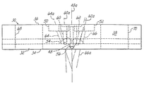
最初に図2〜図8を参照すると、本発明の前提となるノズル30が示されている。ノズル30は、好ましくは黄銅などの金属で形成された本体32を備えており、本体32は、前面34、背面36、上面38及び下面40を有する。V字形ノッチ42が下面40に形成されており、1対の収束するように向き合った側壁42a、42bによって大体画成されている。ノッチ42は、送り込まれた基材ストランド44を、ノズル本体32の空気及び液体出口を通る方向に進めるガイドとして機能する。背面36は、ディスペンサの表面に当てて固定できるようになっており、本体32内へ延在する液体入口ポート46を通してホットメルト接着剤などの液体材料を受け取る。液体入口ポート46はさらに、ノッチ42の中心線43を包含する平面上に延在する長手方向軸線48aを有する液体吐出通路48に連通している。図示されているものでは、軸線48aは、下面40に対して37°の角度をなす。したがって、液体吐出通路48は、背面36に対して鋭角をなす。別のものでは、液体吐出通路と背面36との間の角度が、約60°〜80°である。液体吐出通路48の出口48bが、ノッチ42の頂部付近で前面34に形成された半円形凹部54内に位置している。液体吐出口48bは、半円形凹部54から軸線48aに沿った方向に延出した円錐台形突出部56の頂部に位置している。空気入口凹部50、52が、背面36に形成されて、それぞれ軸線60a、62a、64a、66aに沿って延在する4つの空気吐出通路60、62、64、66と連通している。
Referring initially to FIGS. 2-8, there is shown a
空気吐出通路60、62、64、66は、図3及び図4に最もわかりやすく示された液体吐出口48bに隣接した位置で前面34及び半円形凹部54に設けられた出口60b、62b、64b、66bで終了する。空気吐出通路60、62、64、66は、加圧空気を液体吐出通路48の軸線48aにほぼ向かう方向に複合角度(compound angles)で吐出し、この複合角度は、図3〜図5を見れば最もわかりやすい。ノズル30をディスペンサに取り付けるために使用される締結具33(図1)を受け取るための穴68、70が、本体32に貫設されている。
The
ノズル本体32の前面34から見た時(図3)、空気吐出通路60、64の軸線60a、64aは、液体吐出通路48の軸線48aからそれぞれ約10°及び85°の角度に配置されている。通路62、66の軸線62a、66aは、軸線48aから約65°、及び下面40の側からから測定して軸線48aから40°の角度に配置されている。ノズル本体32の側部から見ると、空気吐出通路60、62、64、66の軸線60a、62a、64a、66aは、図4に最もわかりやすく示されているように、液体吐出通路48の軸線48aに対して約18°、29°、37°及び51°の角度をなす。
When viewed from the
4つの吐出口60b、62b、64b、66bは、ノッチ42内に受け取られる基材の位置に対応した点から共通半径に沿って位置する中心を有する。空気吐出口60b、62b、64b、66bの中心は、ノッチ42の収束側壁42a及び42bが60°の角度だけ分離している時、ノッチ42の頂部から0.027インチ(0.6858mm)の点を中心にした半径に沿った位置にある。これは、断面直径が0.031インチ(0.7874mm)であるストランド44に対応する。
The four
4つの吐出口60b、62b、64b、66bは、図5に示されているように、軸線48aに沿って見た時に液体吐出口48bの下方にほぼ正方形パターンを形成するように配置されている。所望の液体吐出パターンに応じて、他の数、向き及び位置の空気吐出口を代わりに使用してもよいことは、理解されるであろう。空気吐出口60b、62b、64b、66bから出る加圧空気は、通路48から吐出される液体フィラメントに直接的にぶつかるのではなく、通路48から吐出される液体フィラメントに対してほぼ接線方向に向かう。空気吐出口60b、62b、64b、66bから出る加圧空気が液体吐出口48bから出る液体フィラメントに当たることによって発生する渦巻きパターンの大きさは、空気吐出通路60、62、64、66の角度向きを変更することによって調節することができる。
As shown in FIG. 5, the four
図1及び図2は、ノズルの動作、及びノズルによって発生する渦巻きパターンを示す。ストランド44の形の基材がノッチ42内に受け取られて、矢印72で示された方向に移動する。ストランド44が液体吐出口48bの下方を通過する時、液体フィラメント74が出口48bから、やはりほぼ矢印72の方向であるが、同時に下向きの角度をつけて吐出されて、ストランド44に付着する。空気吐出口60b、62b、64b、66bから出る加圧空気ジェットは、図2に矢印76、78、80、82で示されるように、液体フィラメント74の方にほぼ接線方向に向けられる。加圧空気ジェットが液体フィラメント74に渦巻き運動をさせながら、液体フィラメント74はストランド44に付着する。フィラメント74がストランド44に付着した後、液体フィラメント74の一部が重力及び/または遠心力によって引っ張られて、ストランド44に巻き付く。
1 and 2 show the operation of the nozzle and the spiral pattern generated by the nozzle. A substrate in the form of a
図8は、ノズルすなわちダイチップ30’の多くの可能な代替構造のうちの1つを示す。この場合、ノズル30’の前面が平坦面であって、さまざまな通路を下向きに傾斜させるために斜角、すなわち内側に傾斜をつけられていない。他のすべての参照番号は、図1〜図7と図8との間で同一であり、また、図8の説明は、上記のものを参照することができる。
FIG. 8 shows one of many possible alternative structures for the nozzle or die
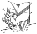
図9〜図14を参照すると、本発明の前提となる吐出モジュール90及びノズル98が示されている。図9に示されている吐出モジュール90は、図1の吐出モジュール10と同様であり、中央本体部分92及び下側本体部分94を有するが、さらに、2003年9月16日に特許付与された本発明の出願人の米国特許第6,619,566号にさらに詳しく説明されているように、吐出モジュール90に対するさまざまなノズルまたはダイの着脱を容易にするための急速着脱機構96を備えている。図9はさらに、吐出モジュール90に連結されて急速着脱機構96で取り付けられた別のノズル98を示す。ノズル30に関して上述したようにして、ノズル98は吐出モジュール90から液体及び加圧空気を受け取って、ダイ98に対してほぼ矢印104の方向に移動する基材102のストランドに液体材料フィラメント100を制御されたパターンで吐出する。
Referring to FIGS. 9 to 14, a discharge module 90 and a
次に図10を参照すると、ノズル98がさらに詳細に示されている。ノズル98は、ノズル本体106を有し、米国特許第6,619,566号にさらに詳しく説明されているように、ノズル98を吐出モジュール90に連結しやすくするために、突出部110、112と傾斜カム面114、116とを備えている。ノズル本体106は、吐出モジュール90の下側部分94に取り付けるように構成された第1側部118を有する。第1側部118には、液体供給ポート120と第1及び第2処理空気供給ポート122、124とが設けられており、これらは、モジュール10について上述したようにして、吐出モジュール90内の対応する液体通路及び空気供給通路に接続される。図10〜図12に示されているように、ノズル本体106は、第2及び第3側部126、128を備えたほぼ楔形の断面を有する。円錐台形突出部130が、ノズル本体106の第2側部126から延出しており、突出部130の先端部に配置された液体吐出口132を備える。液体吐出口132は、液体吐出通路134に流体連通しており、この液体吐出通路134は、液体通路135を介して液体供給ポート120に流体連通しており、それにより、図11及び図12により明らかに示されているように、モジュール90から送られた液体材料を液体吐出口132から基材ストランド102に吐出することができる。液体吐出通路134の少なくとも一部分が、第1側部118に平行な平面に対して鋭角をなす向きにあり、したがって、ほぼ矢印104で示されているストランド102の移動方向に対応した方向に対して角度をなす。液体吐出通路は、第1側部に対して約20°傾斜しており、それにより、液体材料は液体吐出口からストランドに、ほぼストランドの移動方向に吐出される。
Referring now to FIG. 10, the
ノズル本体106の第2側部126はさらに、液体吐出口132付近に複数の空気吐出口136を有し、空気吐出口は、ノズル本体106の第1側部118上の空気供給ポート122、124まで延在しているそれぞれの空気通路139、141を介して空気吐出通路138、140に流体連通している。ノズル本体106の空気吐出通路138、140は、液体通路135を通る軸線から約20°及び約28°傾斜している。図13及び図14に示されているように、空気吐出口136は、円錐台形突出部130の基部をほぼ取り囲んで配置されて、ノズル30に関して上述したようにして、液体吐出口132から吐出される液体フィラメント100の方に処理空気を送るように構成されている。
The
ノズル本体106では、4つの空気吐出口136が円錐台形突出部130の基部で液体吐出口132を取り囲むほぼ正方形のパターンで配置されている。斜め方向に向き合った空気吐出通路138、140、言い換えると、正方形パターンの対向隅部に配置された空気吐出通路は対称的であって、互いに少なくともほぼ平行である平面上に位置している。空気吐出通路138、140の各々は、液体吐出通路134の長手方向軸線に直角をなす軸線152からずれた位置にあって、それぞれ液体吐出通路134の長手方向軸線に対して約30°の真角度をなし、それにより、各空気吐出通路138から吐出された空気流は、液体吐出通路134から吐出された液体フィラメント100に直接的にぶつかるのではなく、液体フィラメント100に対して接線方向になる。空気吐出通路及び液体吐出通路のこのような配置によって、液体吐出通路から吐出される時に制御状態に移動して、基材ストランド102上に所望パターンを形成する液体フィラメントが提供される。当該技術分野の技術者には明らかなように、液体吐出通路134に対する空気吐出通路138、140のずれ間隔及び向きを調節することによって、パターンを変更することが可能である。
In the
ノズル本体106はさらに、ノズル本体106の第2側部126に配置された液体吐出口及び空気吐出口132、136を通り過ぎる向きに基材ストランド102を送るために、第1側部118の反対側で液体吐出口132付近に位置するノズル本体106の端部に形成されたノッチ150を含む。図11及び図12により明確に示されているように、ノッチ150は、ノズル本体106の第2及び第3側部126、128間に延在している。第2及び第3側部126、128は、第1側部118に対して鋭角をなすように構成されている。第2側部126は、第1側部118に対して約60〜80°の角度をなす。第3側部128は、第1側部118に対して約70°未満の角度をなす。好都合なことに、第3側部128の角度により、ストランド102に形成された結び目が、ストランド102の切断を起こすことなく、通過しやすくなる。たとえば、モジュール90を連続動作させるために第1ストランド材の長さの終端部を供給源からの第2ストランド材の長さの先端部に固定する時など、これらの結び目が送り込みストランド材に通常に形成される。
The
本発明の実施形態のノズル200が、図15〜図19に示されている。ノズル200は、図9に示されたものと同様のノズル本体を備えているが、このノズル本体は、変更形ストランドガイドを有する。さらに詳しく言うと、ノズル200は、(図9に示されているように)アプリケーターまたはモジュールに係合させるための上側取り付け面204を有するノズル本体202を備えている。前述した本発明の前提となるものの場合のように、液体入口溝穴206及び一対の処理空気入口溝穴208、210が設けられている。ノズル本体202の前面212に、複数の液体吐出通路214と、各通路214に対応させた処理空気吐出通路216とが設けられている。前述した本発明の前提となるものの場合のように、通路214、216はそれぞれ入口206及び208、210と連通している。
A
ノッチ218の形の複数のストランドガイドが、接着剤を通路214から付与しようとする弾性材料(図示せず)などの材料のそれぞれのストランドを受け取る。ノッチ218は、入口端部218a及び出口端部218bを有する。入口端部218aは、出口端部218bより幅広であり、凹状の、すなわち上向きの丸みを付けた表面220が、入口端部218aから出口端部218bに向かって延在している。図17に示されているように、ストランドガイド面220は、凹状の側面部分220a、220bと、上側の凹面部分220cとを有する。図18に示されているように、表面220は好ましくは、図示のように前から後に、水平に対してたとえば15°だけ傾斜している。ノズル本体202はさらに、前述した本発明の前提となるものの場合と同じ連結目的から、突出部222、224を有する。ストランドがガイドノッチ218を通って移動する時、湾曲した側壁220a、220bによってノッチ内の中心に位置決めされ、それにより、ストランドは、ノッチ218から出る時、液体吐出通路214の真下に位置する。
A plurality of strand guides in the form of
特定の吐出応用例によれば、通路214のうちの対応する通路から接着剤を受け取るストランドの数がストランドガイド、すなわちノッチ218の数と等しいことが、当該技術分野の技術者には理解されるであろう。本発明では、ノズル200は、1本のストランドに接着剤を付与するために1つのノッチ218を、または図15〜図19に示されているように、多数の個別ストランドに接着剤を付与するために多数のノッチ218を組み込むことができると考えられる。
Those skilled in the art will appreciate that, according to a particular dispensing application, the number of strands that receive adhesive from the corresponding one of the
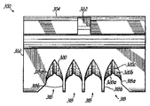
ノズル300の別の実施形態が、図20〜図24に示されている。ノズル300は、図15〜図19に示されているものと同様のノズル本体を備えているが、このノズル本体は、変更形ストランドガイドを有する。さらに詳しく言うと、ノズル300は、(図9に示されているように)アプリケーターまたはモジュールに係合させるための上側取り付け面304を有するノズル本体302を備えている。上述のように、液体入口溝穴306及び一対の処理空気入口溝穴308、310が設けられている。ノズル本体302の前面312に、複数の液体吐出通路314と、各液体吐出通路314に対応させた処理空気吐出通路316とが設けられている。上述のように、通路314、316はそれぞれ入口306及び308、310と連通している。
Another embodiment of the
ノッチ318の形の複数のストランドガイドが、接着剤を通路314から付与しようとする弾性材料102(図23)などの材料のそれぞれのストランドを受け取る。ノッチ318は、入口端部318a及び出口端部318bを有する。入口端部318aは、先行の実施形態の場合のように出口端部318bより幅広でもよいが、図20〜図24に示されているように、ノッチ318全体を幅広にして、ダスト及び/または汚染物質の蓄積をさらに防止してもよい。凹状の、すなわち上向きの丸みを付けた表面320が、入口端部318aから出口端部318bに向かって延在している。図22に示されているように、ストランドガイド面320は、凹状の側面部分320a、320bと、上側のくぼんだ凹部320cとを有する。図23に示されているように、表面320は好ましくは、図示のように前から後に滑らかな曲線をなして傾斜している。これにより、ストランド102は水平に対して約15°〜約45°の角度をなしてノッチ318に入ることができるが、ノッチ318に変更を加えて、または加えないで、他のストランド角度も同様に適応させることができる。ノズル本体302はさらに、前述した本発明の前提となるものの場合と同じ連結目的から、突出部322、324を有する。ストランドがガイドノッチ318を通って移動する時、湾曲した側壁320a、320bによってノッチ内の、また、中央の細長い凹部320c内の中心に位置決めされ、それにより、ストランド102(図23)は、ノッチ318から出る時、液体吐出通路314の真下に位置する。ノッチ318は、空中浮遊汚染物質が、ストランドの切断の原因になる蓄積を生じることなく、ノズル300を自由に通過できるようにする。
A plurality of strand guides in the form of
同様に、特定の吐出応用例によれば、通路314のうちの対応する通路から接着剤を受け取るストランドの数がストランドガイド、すなわちノッチ318の数と等しいことが、当該技術分野の技術者には理解されるであろう。本発明では、ノズル300は、1本のストランドに接着剤を付与するために1つのノッチ318を、または図20〜図24に示されているように、多数の個別ストランドに接着剤を付与するために多数のノッチ318を組み込むことができると考えられる。
Similarly, according to a particular dispensing application, those skilled in the art will recognize that the number of strands that receive adhesive from the corresponding one of the
さまざまな好適な実施形態の記載によって本発明を説明し、これらの実施形態をある程度詳細に記載してきたが、添付の特許請求の範囲をそのような詳細に限定するか、何らかの意味で制限することは、本出願人の意図するところではない。当該技術分野の技術者には、追加の利点及び変更が容易に明らかになるであろう。本発明のさまざまな特徴は、ユーザの必要及び好みによって、単独で、または多くを組み合わせて使用することができる。以上は、現時点で知られる本発明の好適な実施方法と共に本発明を記載するものである。しかし、本発明自体は、添付の特許請求の範囲だけによって定義されるべきである。 Although the invention has been described in terms of various preferred embodiments and these embodiments have been described in some detail, the appended claims should be limited to such details or limited in any way. Is not intended by the applicant. Additional advantages and modifications will be readily apparent to those skilled in the art. The various features of the present invention can be used alone or in combination, depending on the needs and preferences of the user. The foregoing describes the present invention along with the preferred methods of practicing the present invention as currently known. However, the invention itself should be defined solely by the appended claims.
Claims (19)
液体供給ポートと、処理空気供給ポートと、該液体供給ポートに流体連通状態に接続され液体材料をフィラメントの形で吐出する液体吐出口と、該処理空気供給ポートに流体連通状態に接続され該フィラメントに当たるように処理空気を吐出する複数の処理空気吐出口と、弁モジュールに取り付けられるように構成された取り付け面とを有するノズル本体と、
ストランドを受け取るためのノッチを有するストランドガイドと、
を備え、
前記ノッチは、前記液体吐出口の付近に位置しており、且つ、ストランドを受け取って移動経路に沿ってストランドを案内するように構成された丸みがつけられた凹面を有しており、前記ノッチは、入口端部及び出口端部を有し、前記移動経路は、前記入口端部から前記出口端部まで延在しており、前記丸みがつけられた凹面は、前記ノズル本体に対して固定され、且つ、ストランドが前記入口端部を通って移動する際のストランドの複数の進入角度を許容するように前記入口端部から前記出口端部への前記移動経路から離れる方向に傾斜していることを特徴とするノズル。 A nozzle that ejects a controlled pattern of liquid material onto a moving strand along a moving direction ,
A liquid supply port ; a process air supply port ; a liquid discharge port connected to the liquid supply port in fluid communication to discharge liquid material in the form of a filament; and a filament connected to the process air supply port in fluid communication A nozzle body having a plurality of processing air outlets for discharging processing air so as to hit, and an attachment surface configured to be attached to the valve module ;
And the strand guide having the order of the notch receive the strand,
With
The notch has a rounded concave surface located near the liquid discharge port and configured to receive a strand and guide the strand along a movement path, the notch Has an inlet end and an outlet end, the travel path extends from the inlet end to the outlet end, and the rounded concave surface is fixed to the nozzle body. And is inclined in a direction away from the path of travel from the inlet end to the outlet end so as to allow a plurality of strand entry angles as the strand moves through the inlet end. A nozzle characterized by that.
前記処理空気供給ポートに流体連通状態に接続された前記複数の処理空気吐出口は、前記複数の液体吐出口のそれぞれに対して関連付けられており、The plurality of processing air discharge ports connected to the processing air supply port in fluid communication are associated with each of the plurality of liquid discharge ports,
前記ストランドガイドは、前記ノッチが複数設けられており、前記複数のノッチは、それぞれ、前記複数の液体吐出口の付近に位置しており、前記複数のノッチのそれぞれは、複数のストランドのそれぞれを受け取って移動経路に沿ってストランドを案内するように構成された丸みがつけられた凹面を有している請求項1に記載のノズル。The strand guide is provided with a plurality of the notches, and the plurality of notches are respectively located in the vicinity of the plurality of liquid discharge ports, and each of the plurality of notches includes a plurality of strands. The nozzle of claim 1 having a rounded concave surface configured to receive and guide the strand along a travel path.
前記液体吐出口の付近で前記液体吐出口から離れる方向に向いて位置づけられた開口が設けられたノッチと、前記ノズルに固定され、入口端部及び出口端部を有し、前記入口端部から前記出口端部への方向に傾斜している丸みがつけられた凹面と、を備えたストランドガイドを使用し、A notch provided with an opening positioned in the vicinity of the liquid discharge port and facing away from the liquid discharge port; and an inlet end and an outlet end fixed to the nozzle; and from the inlet end Using a strand guide with a rounded concave surface inclined in the direction to the outlet end,
前記移動方向に移動する少なくとも一つのストランドに液体材料を吐出する方法であって、A method of discharging a liquid material onto at least one strand that moves in the moving direction,
前記開口が前記液体吐出口から離れる方向に向いているときに前記開口を通してストランドを前記ノッチに受け、前記入口端部から前記出口端部へ延在する移動経路に沿ってストランドを案内すること、Receiving the strand in the notch through the opening when the opening is directed away from the liquid outlet, and guiding the strand along a movement path extending from the inlet end to the outlet end;
複数の進入角の一つで、且つ、前記移動方向に延在する線に沿って、前記入口端部を通してストランドを移動させること、Moving the strand through the inlet end along one of a plurality of entry angles and along a line extending in the direction of movement;
前記液体吐出口から液体材料をフィラメントの形でストランドへ向けて前記移動方向に対して鋭角に吐出すること、Discharging the liquid material from the liquid discharge port in the form of a filament toward the strand at an acute angle with respect to the moving direction;
前記複数の空気吐出口から空気を吐出して前記フィラメントに当てること、及び、Discharging air from the plurality of air discharge ports and hitting the filament; and
液体材料をストランドに付着させること、Adhering liquid material to the strands;
を含む方法。Including methods.
前記ストランドガイドは、複数の前記ノッチを備え、それぞれのノッチは、前記複数の液体吐出口のそれぞれの付近で前記液体吐出口から離れる方向に向いて位置づけられた開口と、前記ノズルに固定され、入口端部及び出口端部を有し、前記入口端部から前記出口端部への方向に傾斜している丸みがつけられた凹面とを有し、The strand guide includes a plurality of the notches, and each notch is fixed to the nozzle, an opening positioned in a direction away from the liquid discharge port in the vicinity of each of the plurality of liquid discharge ports, A rounded concave surface having an inlet end and an outlet end, inclined in a direction from the inlet end to the outlet end;
前記方法は、The method
それぞれの前記開口が前記複数の液体吐出口から離れる方向に向いているときにそれぞれの前記開口を通して複数のストランドをそれぞれ前記複数のノッチに受け、前記入口端部から前記出口端部へ延在するそれぞれの移動経路に沿ってそれぞれのストランドを案内すること、When each of the openings is directed away from the plurality of liquid discharge ports, the plurality of strands are respectively received by the plurality of notches through the openings and extend from the inlet end to the outlet end. Guiding each strand along each movement path,
複数の進入角の一つで、且つ、前記移動方向に延在する線に沿って、前記複数のノッチのそれぞれの前記入口端部を通して複数のストランドを移動させること、Moving the plurality of strands through the inlet end of each of the plurality of notches along one of a plurality of entry angles and extending in the direction of movement;
前記複数の液体吐出口から液体材料をそれぞれフィラメントの形でそれぞれのストランドへ向けて前記移動方向に対して鋭角に吐出すること、Discharging the liquid material from the plurality of liquid discharge ports in the form of filaments toward the respective strands at an acute angle with respect to the moving direction;
それぞれの前記複数の空気吐出口から空気を吐出してそれぞれの前記フィラメントに当てること、及び、Discharging air from each of the plurality of air outlets and hitting each of the filaments; and
それぞれの前記フィラメントの液体材料をそれぞれのストランドに付着させること、Attaching the liquid material of each said filament to each strand;
を含む請求項12に記載の方法。The method of claim 12 comprising:
前記液体吐出口の付近で前記液体吐出口から離れる方向に向いて位置づけられた開口が設けられたノッチと、前記ノズルに固定され、入口端部及び出口端部を有し、前記入口端部から前記出口端部への方向に傾斜している丸みがつけられた凹面と、を備えたストランドガイドを使用し、A notch provided with an opening positioned in the vicinity of the liquid discharge port and facing away from the liquid discharge port; and an inlet end and an outlet end fixed to the nozzle; and from the inlet end Using a strand guide with a rounded concave surface inclined in the direction to the outlet end,
前記移動方向に移動する少なくとも一つのストランドに液体材料を吐出する方法であって、A method of discharging a liquid material onto at least one strand that moves in the moving direction,
前記開口が前記液体吐出口から離れる方向に向いているときに前記開口を通してストランドを前記ノッチに受け、前記入口端部から前記出口端部へ移動経路に沿ってストランドを案内すること、Receiving the strand in the notch through the opening when the opening is facing away from the liquid discharge port, and guiding the strand along the movement path from the inlet end to the outlet end;
複数の進入角の一つで、且つ、前記移動方向に延在する線に沿って、前記入口端部を通してストランドを移動させること、Moving the strand through the inlet end along one of a plurality of entry angles and along a line extending in the direction of movement;
前記液体吐出口から液体材料をフィラメントの形で吐出すること、Discharging the liquid material from the liquid discharge port in the form of a filament;
前記複数の空気吐出口から空気を吐出して前記フィラメントに当てること、及び、Discharging air from the plurality of air discharge ports and hitting the filament; and
液体材料をストランドに付着させること、Adhering liquid material to the strands;
を含む方法。Including methods.
前記ストランドガイドは、複数の前記ノッチを備え、それぞれのノッチは、前記複数の液体吐出口のそれぞれの付近で前記液体吐出口から離れる方向に向いて位置づけられた開口と、前記ノズルに固定され、入口端部及び出口端部を有し、前記入口端部から前記出口端部への方向に傾斜している丸みがつけられた凹面とを有し、The strand guide includes a plurality of the notches, and each notch is fixed to the nozzle, an opening positioned in a direction away from the liquid discharge port in the vicinity of each of the plurality of liquid discharge ports, A rounded concave surface having an inlet end and an outlet end, inclined in a direction from the inlet end to the outlet end;
前記方法は、The method
それぞれの前記開口が前記複数の液体吐出口から離れる方向に向いているときにそれぞれの前記開口を通して複数のストランドをそれぞれ前記複数のノッチに受け、前記入口端部から前記出口端部へ延在するそれぞれの移動経路に沿ってそれぞれのストランドを案内すること、When each of the openings is directed away from the plurality of liquid discharge ports, the plurality of strands are respectively received by the plurality of notches through the openings and extend from the inlet end to the outlet end. Guiding each strand along each movement path,
複数の進入角の一つで、且つ、前記移動方向に延在する線に沿って、前記複数のノッチのそれぞれの前記入口端部を通して複数のストランドを移動させること、Moving the plurality of strands through the inlet end of each of the plurality of notches along one of a plurality of entry angles and extending in the direction of movement;
前記複数の液体吐出口から液体材料をそれぞれフィラメントの形で吐出すること、Discharging liquid material in the form of filaments from the plurality of liquid discharge ports,
それぞれの前記複数の空気吐出口から空気を吐出してそれぞれの前記フィラメントに当てること、及び、Discharging air from each of the plurality of air outlets and hitting each of the filaments; and
それぞれの前記フィラメントの液体材料をそれぞれのストランドに付着させること、Attaching the liquid material of each said filament to each strand;
を含む請求項16に記載の方法。The method of claim 16 comprising:
Applications Claiming Priority (2)
| Application Number | Priority Date | Filing Date | Title |
|---|---|---|---|
| US44174903P | 2003-01-22 | 2003-01-22 | |
| US10/760,911 US7578882B2 (en) | 2003-01-22 | 2004-01-20 | Module, nozzle and method for dispensing controlled patterns of liquid material |
Publications (3)
| Publication Number | Publication Date |
|---|---|
| JP2004261794A JP2004261794A (en) | 2004-09-24 |
| JP2004261794A5 JP2004261794A5 (en) | 2007-03-08 |
| JP4638674B2 true JP4638674B2 (en) | 2011-02-23 |
Family
ID=32600301
Family Applications (1)
| Application Number | Title | Priority Date | Filing Date |
|---|---|---|---|
| JP2004014629A Expired - Fee Related JP4638674B2 (en) | 2003-01-22 | 2004-01-22 | Nozzle and method for discharging liquid material |
Country Status (4)
| Country | Link |
|---|---|
| US (1) | US7578882B2 (en) |
| EP (1) | EP1440736B1 (en) |
| JP (1) | JP4638674B2 (en) |
| DE (1) | DE602004029110D1 (en) |
Cited By (1)
| Publication number | Priority date | Publication date | Assignee | Title |
|---|---|---|---|---|
| JP2013215580A (en) * | 2012-04-11 | 2013-10-24 | Nordson Corp | Method and apparatus for applying adhesive on elastic strand in personal disposable hygiene product |
Families Citing this family (16)
| Publication number | Priority date | Publication date | Assignee | Title |
|---|---|---|---|---|
| US6911232B2 (en) | 2002-04-12 | 2005-06-28 | Nordson Corporation | Module, nozzle and method for dispensing controlled patterns of liquid material |
| US7578882B2 (en) * | 2003-01-22 | 2009-08-25 | Nordson Corporation | Module, nozzle and method for dispensing controlled patterns of liquid material |
| JP4862114B2 (en) * | 2005-05-02 | 2012-01-25 | 株式会社サンツール | Method for applying adhesive to elastic string-like body in application line and apparatus for applying adhesive to elastic string-like body |
| JP2010523318A (en) * | 2007-04-03 | 2010-07-15 | ノードソン コーポレーション | Protective member and nozzle assembly configured to withstand wear |
| JP5235343B2 (en) * | 2007-07-02 | 2013-07-10 | 株式会社リブドゥコーポレーション | Adhesive application nozzle and adhesive application device |
| JP5408479B2 (en) * | 2009-03-25 | 2014-02-05 | ノードソン株式会社 | Liquid application nozzle for flat objects |
| JP5676877B2 (en) * | 2009-12-28 | 2015-02-25 | ユニ・チャーム株式会社 | Nozzle device and diaper having a stretchable sheet manufactured using the same |
| US9168554B2 (en) * | 2011-04-11 | 2015-10-27 | Nordson Corporation | System, nozzle, and method for coating elastic strands |
| US8794491B2 (en) | 2011-10-28 | 2014-08-05 | Nordson Corporation | Dispensing module and method of dispensing with a pneumatic actuator |
| US8720517B2 (en) | 2012-03-12 | 2014-05-13 | Nordson Corporation | System and method for applying individually coated non-linear elastic strands to a substrate |
| DE102013204211A1 (en) | 2012-03-13 | 2013-09-19 | Nordson Corporation | Method for manufacturing disposable absorbent personal hygiene product e.g. diaper, involves expanding foamed adhesive on stretched elastic strand and joining stretched elastic strand with non-woven fabric substrate by foamed adhesive |
| US9682392B2 (en) | 2012-04-11 | 2017-06-20 | Nordson Corporation | Method for applying varying amounts or types of adhesive on an elastic strand |
| US8961720B2 (en) | 2012-11-26 | 2015-02-24 | Nordson Corporation | Method for guiding and bonding strands to a substrate |
| US9908137B2 (en) * | 2013-11-14 | 2018-03-06 | Illinois Tool Works Inc. | Fluid application device having a modular non-contact nozzle for applying fluid to an article |
| US20150314319A1 (en) * | 2014-04-30 | 2015-11-05 | Illinois Tool Works Inc. | Fluid application device, slot die applicator and guide form for fluid application device |
| JP2017148505A (en) | 2016-02-25 | 2017-08-31 | ノードソン コーポレーションNordson Corporation | Method, apparatus and nozzle for applying varying amounts or types of adhesive on elastic strand |
Citations (11)
| Publication number | Priority date | Publication date | Assignee | Title |
|---|---|---|---|---|
| US2841020A (en) * | 1954-01-05 | 1958-07-01 | Iv Christopher Van Deventer | Sheave assemblies for looms |
| JPH02289165A (en) * | 1988-12-07 | 1990-11-29 | Nordson Corp | Apparatus for applying adhesive to elastic string |
| JPH0625927A (en) * | 1992-03-23 | 1994-02-01 | Toray Ind Inc | Draw false-twisting method and draw false-twisting machine |
| JP2001259497A (en) * | 2000-03-14 | 2001-09-25 | Nordson Kk | Device and method for applying adhesive on yarn or lace like body |
| JP2002105881A (en) * | 2000-07-24 | 2002-04-10 | Illinois Tool Works Inc <Itw> | Tool for coating strand |
| JP2002512122A (en) * | 1998-04-17 | 2002-04-23 | ノードソン コーポレーション | Method and apparatus for applying a controlled pattern of fibrous material to a moving support |
| JP2002339226A (en) * | 2001-03-23 | 2002-11-27 | Nordson Corp | Guide system for positioning elongated strand in liquid dispensing environment |
| JP2002361123A (en) * | 2001-03-22 | 2002-12-17 | Nordson Corp | All-round distribution system for pushing out filamentous liquid by support of air |
| US20030200921A1 (en) * | 2002-04-12 | 2003-10-30 | Nordson Corporation | Module, nozzle and method for dispensing controlled patterns of liquid material |
| US20040144494A1 (en) * | 2003-01-22 | 2004-07-29 | Nordson Corporation | Module, nozzle and method for dispensing controlled patterns of liquid material |
| US20040164180A1 (en) * | 2003-01-24 | 2004-08-26 | Nordson Corporation | Module, nozzle and method for dispensing controlled patterns of liquid material |
Family Cites Families (44)
| Publication number | Priority date | Publication date | Assignee | Title |
|---|---|---|---|---|
| CA1025291A (en) * | 1973-11-19 | 1978-01-31 | Usm Corporation | Adhesive process and apparatus |
| US3997308A (en) * | 1975-03-31 | 1976-12-14 | Ppg Industries, Inc. | Apparatus for gathering fibers into a plurality of spaced apart strands |
| JPS5857374B2 (en) * | 1975-08-20 | 1983-12-20 | 日本板硝子株式会社 | Fiber manufacturing method |
| US4185981A (en) * | 1975-08-20 | 1980-01-29 | Nippon Sheet Glass Co.,Ltd. | Method for producing fibers from heat-softening materials |
| US4048861A (en) * | 1976-02-02 | 1977-09-20 | Johns-Manville Corporation | Device for oscillating a rotating body along its rotational axis |
| US4222758A (en) * | 1978-12-27 | 1980-09-16 | Owens-Corning Fiberglas Corporation | Apparatus for processing filaments |
| FR2490079A1 (en) * | 1980-09-15 | 1982-03-19 | Boussac Saint Freres Bsf | PROCESS FOR MANUFACTURING CUTTING LAYERS AND CUTTING LAYERS OBTAINED BY CARRYING OUT SAID METHOD |
| JPS58180601A (en) | 1982-04-14 | 1983-10-22 | ユニ・チヤ−ム株式会社 | Disposable diaper and attachment of elastic member thereof |
| EP0097414A1 (en) | 1982-04-29 | 1984-01-04 | AMP INCORPORATED (a New Jersey corporation) | Multiconductor flat cable, and method and apparatus for manufacturing it |
| FR2539274A1 (en) * | 1983-01-19 | 1984-07-20 | Boussac Saint Freres Bsf | PROCESS FOR MANUFACTURING JET-CUTTING LAYERS AND GUITAR LAYERS OBTAINED |
| US4801051A (en) * | 1984-03-26 | 1989-01-31 | Nordson Corporation | Flow control device for a fluid dispensing apparatus |
| JPH0815490B2 (en) | 1984-12-25 | 1996-02-21 | 株式会社瑞光 | Method of manufacturing disposable diapers |
| ES2042612T3 (en) * | 1987-03-07 | 1993-12-16 | Fuller H B Licensing Financ | PROCEDURE FOR THE PERMANENT JOINING OF EXPANDABLE ELEMENTS IN THE FORM OF THREADS OR RIBBONS ON A SURFACE SUBSTRATE AS WELL AS USING IT FOR THE MANUFACTURE OF CURLED LEAF BAND SECTORS. |
| DE3744587A1 (en) | 1987-12-31 | 1989-07-13 | Dittberner Gmbh Klebstoff Auft | METHOD FOR APPLYING GLUE TO ENDLESS THREADS AND CORRESPONDING DEVICE |
| US5171512A (en) * | 1988-03-25 | 1992-12-15 | Mitsui Petrochemical Industries, Ltd. | Melt-blowing method having notches on the capillary tips |
| US4949668A (en) * | 1988-06-16 | 1990-08-21 | Kimberly-Clark Corporation | Apparatus for sprayed adhesive diaper construction |
| US4844003A (en) * | 1988-06-30 | 1989-07-04 | Slautterback Corporation | Hot-melt applicator |
| DE8901172U1 (en) | 1989-02-02 | 1990-06-07 | Nordson Corp., Westlake, Ohio, Us | |
| DE8815242U1 (en) | 1988-12-07 | 1990-05-10 | Nordson Corp., Westlake, Ohio, Us | |
| US5267693A (en) * | 1992-02-12 | 1993-12-07 | Dickey Barry A | Spray gun non-stick paint connector block |
| US5277344A (en) * | 1992-10-05 | 1994-01-11 | Nordson Corporation | Flow control device for fluid dispenser |
| US5540774A (en) * | 1992-10-19 | 1996-07-30 | Illinois Tool Works Inc. | Drip proof dispensing method and nozzle assembly for dispensing viscous materials |
| US5785258A (en) * | 1993-10-08 | 1998-07-28 | Vortexx Group Incorporated | Method and apparatus for conditioning fluid flow |
| CA2149700A1 (en) | 1994-08-12 | 1996-02-13 | Brendon Frank Ribble | Method for applying an elastic member to a moving substrate |
| DE9420324U1 (en) * | 1994-12-20 | 1995-02-09 | Chiron Werke Gmbh | Air head |
| US5553758A (en) * | 1995-01-27 | 1996-09-10 | Melendy; Peter S. | Nozzle adaptor for applying hot melt adhesive |
| US6527369B1 (en) | 1995-10-25 | 2003-03-04 | Hewlett-Packard Company | Asymmetric printhead orifice |
| US6253957B1 (en) * | 1995-11-16 | 2001-07-03 | Nordson Corporation | Method and apparatus for dispensing small amounts of liquid material |
| US5904298A (en) * | 1996-10-08 | 1999-05-18 | Illinois Tool Works Inc. | Meltblowing method and system |
| US5902540A (en) * | 1996-10-08 | 1999-05-11 | Illinois Tool Works Inc. | Meltblowing method and apparatus |
| US5882573A (en) * | 1997-09-29 | 1999-03-16 | Illinois Tool Works Inc. | Adhesive dispensing nozzles for producing partial spray patterns and method therefor |
| US6067928A (en) * | 1997-10-02 | 2000-05-30 | Basf Corporation | Filament guide assembly especially useful in combination with filament finish applicators |
| JPH11244774A (en) | 1998-02-28 | 1999-09-14 | San Tool:Kk | Spiral application method of adhesive |
| US6077375A (en) * | 1998-04-15 | 2000-06-20 | Illinois Tool Works Inc. | Elastic strand coating process |
| JPH11319674A (en) * | 1998-05-17 | 1999-11-24 | San Tool:Kk | Nozzle device and gun unit for adhesive spiral spray coating apparatus |
| US6250357B1 (en) * | 1999-03-15 | 2001-06-26 | William P. Niedermeyer | Method and apparatus for briefs with pad support panel |
| US6435425B1 (en) * | 2000-05-15 | 2002-08-20 | Nordson Corporation | Module and nozzle for dispensing controlled patterns of liquid material |
| JP2001347209A (en) | 2000-06-07 | 2001-12-18 | Suntool Corp | Method and apparatus for applying adhesive to string rubber or the like in a coating line |
| US7118558B2 (en) * | 2001-11-06 | 2006-10-10 | Tyco Healthcare Retail Services Ag | Cloth-like laminate and absorbent garment |
| US20030089447A1 (en) * | 2001-11-06 | 2003-05-15 | Kenneth Molee | Soft absorbent garment made with discretely coated elastic elements, and system and method for making a soft absorbent garment |
| US20030173024A1 (en) * | 2002-03-15 | 2003-09-18 | Nordson Corporation | Method of securing elastic strands to flat substrates and products produced by the method |
| US20050013975A1 (en) * | 2003-07-14 | 2005-01-20 | Nordson Corporation | Method of securing elastic strands to flat substrates and products produced by the method |
| US6936125B2 (en) * | 2002-03-15 | 2005-08-30 | Nordson Corporation | Method of applying a continuous adhesive filament to an elastic strand with discrete bond points and articles manufactured by the method |
| AU2003239136A1 (en) * | 2002-04-12 | 2003-10-27 | Nordson Corporation | Applicator and nozzle for dispensing controlled patterns of liquid material |
-
2004
- 2004-01-20 US US10/760,911 patent/US7578882B2/en not_active Expired - Fee Related
- 2004-01-22 JP JP2004014629A patent/JP4638674B2/en not_active Expired - Fee Related
- 2004-01-22 DE DE602004029110T patent/DE602004029110D1/en not_active Expired - Lifetime
- 2004-01-22 EP EP04001330A patent/EP1440736B1/en not_active Expired - Fee Related
Patent Citations (12)
| Publication number | Priority date | Publication date | Assignee | Title |
|---|---|---|---|---|
| US2841020A (en) * | 1954-01-05 | 1958-07-01 | Iv Christopher Van Deventer | Sheave assemblies for looms |
| JPH02289165A (en) * | 1988-12-07 | 1990-11-29 | Nordson Corp | Apparatus for applying adhesive to elastic string |
| JPH0625927A (en) * | 1992-03-23 | 1994-02-01 | Toray Ind Inc | Draw false-twisting method and draw false-twisting machine |
| JP2002512122A (en) * | 1998-04-17 | 2002-04-23 | ノードソン コーポレーション | Method and apparatus for applying a controlled pattern of fibrous material to a moving support |
| JP2001259497A (en) * | 2000-03-14 | 2001-09-25 | Nordson Kk | Device and method for applying adhesive on yarn or lace like body |
| JP2002105881A (en) * | 2000-07-24 | 2002-04-10 | Illinois Tool Works Inc <Itw> | Tool for coating strand |
| JP2002361123A (en) * | 2001-03-22 | 2002-12-17 | Nordson Corp | All-round distribution system for pushing out filamentous liquid by support of air |
| JP2002339226A (en) * | 2001-03-23 | 2002-11-27 | Nordson Corp | Guide system for positioning elongated strand in liquid dispensing environment |
| US20030200921A1 (en) * | 2002-04-12 | 2003-10-30 | Nordson Corporation | Module, nozzle and method for dispensing controlled patterns of liquid material |
| US20050205689A1 (en) * | 2002-04-12 | 2005-09-22 | Nordson Corporation | Module, nozzle and method for dispensing controlled patterns of liquid material |
| US20040144494A1 (en) * | 2003-01-22 | 2004-07-29 | Nordson Corporation | Module, nozzle and method for dispensing controlled patterns of liquid material |
| US20040164180A1 (en) * | 2003-01-24 | 2004-08-26 | Nordson Corporation | Module, nozzle and method for dispensing controlled patterns of liquid material |
Cited By (3)
| Publication number | Priority date | Publication date | Assignee | Title |
|---|---|---|---|---|
| JP2013215580A (en) * | 2012-04-11 | 2013-10-24 | Nordson Corp | Method and apparatus for applying adhesive on elastic strand in personal disposable hygiene product |
| US9907705B2 (en) | 2012-04-11 | 2018-03-06 | Nordson Corporation | Dispensing apparatus for applying adhesive on an elastic strand in assembly of a personal disposable hygiene product |
| US9962298B2 (en) | 2012-04-11 | 2018-05-08 | Nordson Corporation | Dispensing apparatus for applying adhesive on an elastic strand in a personal disposable hygiene product |
Also Published As
| Publication number | Publication date |
|---|---|
| EP1440736A2 (en) | 2004-07-28 |
| EP1440736A3 (en) | 2007-03-28 |
| US7578882B2 (en) | 2009-08-25 |
| US20040144494A1 (en) | 2004-07-29 |
| EP1440736B1 (en) | 2010-09-15 |
| JP2004261794A (en) | 2004-09-24 |
| DE602004029110D1 (en) | 2010-10-28 |
Similar Documents
| Publication | Publication Date | Title |
|---|---|---|
| JP4638674B2 (en) | Nozzle and method for discharging liquid material | |
| US7950346B2 (en) | Module, nozzle and method for dispensing controlled patterns of liquid material | |
| US7255292B2 (en) | Module and nozzle for dispensing controlled patterns of liquid material | |
| JP5502361B2 (en) | Nozzle and method for discharging adhesive filament in random pattern | |
| US8535756B2 (en) | Method for dispensing random pattern of adhesive filaments | |
| US7121479B2 (en) | Universal dispensing system for air assisted extrusion of liquid filaments | |
| JP2002512122A (en) | Method and apparatus for applying a controlled pattern of fibrous material to a moving support | |
| US7462240B2 (en) | Module, nozzle and method for dispensing controlled patterns of liquid material | |
| JP2002018325A (en) | Module for discharging material liquid after controlled pattern and nozzle having asymmetric liquid discharge orifice |
Legal Events
| Date | Code | Title | Description |
|---|---|---|---|
| A521 | Written amendment |
Free format text: JAPANESE INTERMEDIATE CODE: A523 Effective date: 20070122 |
|
| A621 | Written request for application examination |
Free format text: JAPANESE INTERMEDIATE CODE: A621 Effective date: 20070122 |
|
| A131 | Notification of reasons for refusal |
Free format text: JAPANESE INTERMEDIATE CODE: A131 Effective date: 20090713 |
|
| A601 | Written request for extension of time |
Free format text: JAPANESE INTERMEDIATE CODE: A601 Effective date: 20091013 |
|
| A602 | Written permission of extension of time |
Free format text: JAPANESE INTERMEDIATE CODE: A602 Effective date: 20091016 |
|
| A521 | Written amendment |
Free format text: JAPANESE INTERMEDIATE CODE: A523 Effective date: 20100113 |
|
| A131 | Notification of reasons for refusal |
Free format text: JAPANESE INTERMEDIATE CODE: A131 Effective date: 20100712 |
|
| A521 | Written amendment |
Free format text: JAPANESE INTERMEDIATE CODE: A523 Effective date: 20101012 |
|
| RD02 | Notification of acceptance of power of attorney |
Free format text: JAPANESE INTERMEDIATE CODE: A7422 Effective date: 20101012 |
|
| TRDD | Decision of grant or rejection written | ||
| A01 | Written decision to grant a patent or to grant a registration (utility model) |
Free format text: JAPANESE INTERMEDIATE CODE: A01 Effective date: 20101104 |
|
| A01 | Written decision to grant a patent or to grant a registration (utility model) |
Free format text: JAPANESE INTERMEDIATE CODE: A01 |
|
| A61 | First payment of annual fees (during grant procedure) |
Free format text: JAPANESE INTERMEDIATE CODE: A61 Effective date: 20101126 |
|
| FPAY | Renewal fee payment (event date is renewal date of database) |
Free format text: PAYMENT UNTIL: 20131203 Year of fee payment: 3 |
|
| R150 | Certificate of patent or registration of utility model |
Ref document number: 4638674 Country of ref document: JP Free format text: JAPANESE INTERMEDIATE CODE: R150 Free format text: JAPANESE INTERMEDIATE CODE: R150 |
|
| R250 | Receipt of annual fees |
Free format text: JAPANESE INTERMEDIATE CODE: R250 |
|
| R250 | Receipt of annual fees |
Free format text: JAPANESE INTERMEDIATE CODE: R250 |
|
| R250 | Receipt of annual fees |
Free format text: JAPANESE INTERMEDIATE CODE: R250 |
|
| R250 | Receipt of annual fees |
Free format text: JAPANESE INTERMEDIATE CODE: R250 |
|
| R250 | Receipt of annual fees |
Free format text: JAPANESE INTERMEDIATE CODE: R250 |
|
| R250 | Receipt of annual fees |
Free format text: JAPANESE INTERMEDIATE CODE: R250 |
|
| R250 | Receipt of annual fees |
Free format text: JAPANESE INTERMEDIATE CODE: R250 |
|
| LAPS | Cancellation because of no payment of annual fees |