JP4636634B2 - Intravascular stent - Google Patents
Intravascular stent Download PDFInfo
- Publication number
- JP4636634B2 JP4636634B2 JP53903197A JP53903197A JP4636634B2 JP 4636634 B2 JP4636634 B2 JP 4636634B2 JP 53903197 A JP53903197 A JP 53903197A JP 53903197 A JP53903197 A JP 53903197A JP 4636634 B2 JP4636634 B2 JP 4636634B2
- Authority
- JP
- Japan
- Prior art keywords
- strut
- expansion
- pair
- column
- stent
- Prior art date
- Legal status (The legal status is an assumption and is not a legal conclusion. Google has not performed a legal analysis and makes no representation as to the accuracy of the status listed.)
- Expired - Lifetime
Links
Images


Classifications
-
- A—HUMAN NECESSITIES
- A61—MEDICAL OR VETERINARY SCIENCE; HYGIENE
- A61F—FILTERS IMPLANTABLE INTO BLOOD VESSELS; PROSTHESES; DEVICES PROVIDING PATENCY TO, OR PREVENTING COLLAPSING OF, TUBULAR STRUCTURES OF THE BODY, e.g. STENTS; ORTHOPAEDIC, NURSING OR CONTRACEPTIVE DEVICES; FOMENTATION; TREATMENT OR PROTECTION OF EYES OR EARS; BANDAGES, DRESSINGS OR ABSORBENT PADS; FIRST-AID KITS
- A61F2/00—Filters implantable into blood vessels; Prostheses, i.e. artificial substitutes or replacements for parts of the body; Appliances for connecting them with the body; Devices providing patency to, or preventing collapsing of, tubular structures of the body, e.g. stents
- A61F2/82—Devices providing patency to, or preventing collapsing of, tubular structures of the body, e.g. stents
- A61F2/86—Stents in a form characterised by the wire-like elements; Stents in the form characterised by a net-like or mesh-like structure
- A61F2/90—Stents in a form characterised by the wire-like elements; Stents in the form characterised by a net-like or mesh-like structure characterised by a net-like or mesh-like structure
- A61F2/91—Stents in a form characterised by the wire-like elements; Stents in the form characterised by a net-like or mesh-like structure characterised by a net-like or mesh-like structure made from perforated sheets or tubes, e.g. perforated by laser cuts or etched holes
- A61F2/915—Stents in a form characterised by the wire-like elements; Stents in the form characterised by a net-like or mesh-like structure characterised by a net-like or mesh-like structure made from perforated sheets or tubes, e.g. perforated by laser cuts or etched holes with bands having a meander structure, adjacent bands being connected to each other
-
- A—HUMAN NECESSITIES
- A61—MEDICAL OR VETERINARY SCIENCE; HYGIENE
- A61F—FILTERS IMPLANTABLE INTO BLOOD VESSELS; PROSTHESES; DEVICES PROVIDING PATENCY TO, OR PREVENTING COLLAPSING OF, TUBULAR STRUCTURES OF THE BODY, e.g. STENTS; ORTHOPAEDIC, NURSING OR CONTRACEPTIVE DEVICES; FOMENTATION; TREATMENT OR PROTECTION OF EYES OR EARS; BANDAGES, DRESSINGS OR ABSORBENT PADS; FIRST-AID KITS
- A61F2/00—Filters implantable into blood vessels; Prostheses, i.e. artificial substitutes or replacements for parts of the body; Appliances for connecting them with the body; Devices providing patency to, or preventing collapsing of, tubular structures of the body, e.g. stents
- A61F2/82—Devices providing patency to, or preventing collapsing of, tubular structures of the body, e.g. stents
- A61F2/86—Stents in a form characterised by the wire-like elements; Stents in the form characterised by a net-like or mesh-like structure
- A61F2/90—Stents in a form characterised by the wire-like elements; Stents in the form characterised by a net-like or mesh-like structure characterised by a net-like or mesh-like structure
- A61F2/91—Stents in a form characterised by the wire-like elements; Stents in the form characterised by a net-like or mesh-like structure characterised by a net-like or mesh-like structure made from perforated sheets or tubes, e.g. perforated by laser cuts or etched holes
-
- A—HUMAN NECESSITIES
- A61—MEDICAL OR VETERINARY SCIENCE; HYGIENE
- A61F—FILTERS IMPLANTABLE INTO BLOOD VESSELS; PROSTHESES; DEVICES PROVIDING PATENCY TO, OR PREVENTING COLLAPSING OF, TUBULAR STRUCTURES OF THE BODY, e.g. STENTS; ORTHOPAEDIC, NURSING OR CONTRACEPTIVE DEVICES; FOMENTATION; TREATMENT OR PROTECTION OF EYES OR EARS; BANDAGES, DRESSINGS OR ABSORBENT PADS; FIRST-AID KITS
- A61F2/00—Filters implantable into blood vessels; Prostheses, i.e. artificial substitutes or replacements for parts of the body; Appliances for connecting them with the body; Devices providing patency to, or preventing collapsing of, tubular structures of the body, e.g. stents
- A61F2/95—Instruments specially adapted for placement or removal of stents or stent-grafts
- A61F2/958—Inflatable balloons for placing stents or stent-grafts
-
- A—HUMAN NECESSITIES
- A61—MEDICAL OR VETERINARY SCIENCE; HYGIENE
- A61F—FILTERS IMPLANTABLE INTO BLOOD VESSELS; PROSTHESES; DEVICES PROVIDING PATENCY TO, OR PREVENTING COLLAPSING OF, TUBULAR STRUCTURES OF THE BODY, e.g. STENTS; ORTHOPAEDIC, NURSING OR CONTRACEPTIVE DEVICES; FOMENTATION; TREATMENT OR PROTECTION OF EYES OR EARS; BANDAGES, DRESSINGS OR ABSORBENT PADS; FIRST-AID KITS
- A61F2/00—Filters implantable into blood vessels; Prostheses, i.e. artificial substitutes or replacements for parts of the body; Appliances for connecting them with the body; Devices providing patency to, or preventing collapsing of, tubular structures of the body, e.g. stents
- A61F2/82—Devices providing patency to, or preventing collapsing of, tubular structures of the body, e.g. stents
- A61F2/86—Stents in a form characterised by the wire-like elements; Stents in the form characterised by a net-like or mesh-like structure
- A61F2/90—Stents in a form characterised by the wire-like elements; Stents in the form characterised by a net-like or mesh-like structure characterised by a net-like or mesh-like structure
- A61F2/91—Stents in a form characterised by the wire-like elements; Stents in the form characterised by a net-like or mesh-like structure characterised by a net-like or mesh-like structure made from perforated sheets or tubes, e.g. perforated by laser cuts or etched holes
- A61F2/915—Stents in a form characterised by the wire-like elements; Stents in the form characterised by a net-like or mesh-like structure characterised by a net-like or mesh-like structure made from perforated sheets or tubes, e.g. perforated by laser cuts or etched holes with bands having a meander structure, adjacent bands being connected to each other
- A61F2002/91525—Stents in a form characterised by the wire-like elements; Stents in the form characterised by a net-like or mesh-like structure characterised by a net-like or mesh-like structure made from perforated sheets or tubes, e.g. perforated by laser cuts or etched holes with bands having a meander structure, adjacent bands being connected to each other within the whole structure different bands showing different meander characteristics, e.g. frequency or amplitude
-
- A—HUMAN NECESSITIES
- A61—MEDICAL OR VETERINARY SCIENCE; HYGIENE
- A61F—FILTERS IMPLANTABLE INTO BLOOD VESSELS; PROSTHESES; DEVICES PROVIDING PATENCY TO, OR PREVENTING COLLAPSING OF, TUBULAR STRUCTURES OF THE BODY, e.g. STENTS; ORTHOPAEDIC, NURSING OR CONTRACEPTIVE DEVICES; FOMENTATION; TREATMENT OR PROTECTION OF EYES OR EARS; BANDAGES, DRESSINGS OR ABSORBENT PADS; FIRST-AID KITS
- A61F2/00—Filters implantable into blood vessels; Prostheses, i.e. artificial substitutes or replacements for parts of the body; Appliances for connecting them with the body; Devices providing patency to, or preventing collapsing of, tubular structures of the body, e.g. stents
- A61F2/82—Devices providing patency to, or preventing collapsing of, tubular structures of the body, e.g. stents
- A61F2/86—Stents in a form characterised by the wire-like elements; Stents in the form characterised by a net-like or mesh-like structure
- A61F2/90—Stents in a form characterised by the wire-like elements; Stents in the form characterised by a net-like or mesh-like structure characterised by a net-like or mesh-like structure
- A61F2/91—Stents in a form characterised by the wire-like elements; Stents in the form characterised by a net-like or mesh-like structure characterised by a net-like or mesh-like structure made from perforated sheets or tubes, e.g. perforated by laser cuts or etched holes
- A61F2/915—Stents in a form characterised by the wire-like elements; Stents in the form characterised by a net-like or mesh-like structure characterised by a net-like or mesh-like structure made from perforated sheets or tubes, e.g. perforated by laser cuts or etched holes with bands having a meander structure, adjacent bands being connected to each other
- A61F2002/91533—Stents in a form characterised by the wire-like elements; Stents in the form characterised by a net-like or mesh-like structure characterised by a net-like or mesh-like structure made from perforated sheets or tubes, e.g. perforated by laser cuts or etched holes with bands having a meander structure, adjacent bands being connected to each other characterised by the phase between adjacent bands
-
- A—HUMAN NECESSITIES
- A61—MEDICAL OR VETERINARY SCIENCE; HYGIENE
- A61F—FILTERS IMPLANTABLE INTO BLOOD VESSELS; PROSTHESES; DEVICES PROVIDING PATENCY TO, OR PREVENTING COLLAPSING OF, TUBULAR STRUCTURES OF THE BODY, e.g. STENTS; ORTHOPAEDIC, NURSING OR CONTRACEPTIVE DEVICES; FOMENTATION; TREATMENT OR PROTECTION OF EYES OR EARS; BANDAGES, DRESSINGS OR ABSORBENT PADS; FIRST-AID KITS
- A61F2/00—Filters implantable into blood vessels; Prostheses, i.e. artificial substitutes or replacements for parts of the body; Appliances for connecting them with the body; Devices providing patency to, or preventing collapsing of, tubular structures of the body, e.g. stents
- A61F2/82—Devices providing patency to, or preventing collapsing of, tubular structures of the body, e.g. stents
- A61F2/86—Stents in a form characterised by the wire-like elements; Stents in the form characterised by a net-like or mesh-like structure
- A61F2/90—Stents in a form characterised by the wire-like elements; Stents in the form characterised by a net-like or mesh-like structure characterised by a net-like or mesh-like structure
- A61F2/91—Stents in a form characterised by the wire-like elements; Stents in the form characterised by a net-like or mesh-like structure characterised by a net-like or mesh-like structure made from perforated sheets or tubes, e.g. perforated by laser cuts or etched holes
- A61F2/915—Stents in a form characterised by the wire-like elements; Stents in the form characterised by a net-like or mesh-like structure characterised by a net-like or mesh-like structure made from perforated sheets or tubes, e.g. perforated by laser cuts or etched holes with bands having a meander structure, adjacent bands being connected to each other
- A61F2002/9155—Adjacent bands being connected to each other
- A61F2002/91558—Adjacent bands being connected to each other connected peak to peak
-
- A—HUMAN NECESSITIES
- A61—MEDICAL OR VETERINARY SCIENCE; HYGIENE
- A61F—FILTERS IMPLANTABLE INTO BLOOD VESSELS; PROSTHESES; DEVICES PROVIDING PATENCY TO, OR PREVENTING COLLAPSING OF, TUBULAR STRUCTURES OF THE BODY, e.g. STENTS; ORTHOPAEDIC, NURSING OR CONTRACEPTIVE DEVICES; FOMENTATION; TREATMENT OR PROTECTION OF EYES OR EARS; BANDAGES, DRESSINGS OR ABSORBENT PADS; FIRST-AID KITS
- A61F2230/00—Geometry of prostheses classified in groups A61F2/00 - A61F2/26 or A61F2/82 or A61F9/00 or A61F11/00 or subgroups thereof
- A61F2230/0002—Two-dimensional shapes, e.g. cross-sections
- A61F2230/0028—Shapes in the form of latin or greek characters
- A61F2230/0054—V-shaped
-
- A—HUMAN NECESSITIES
- A61—MEDICAL OR VETERINARY SCIENCE; HYGIENE
- A61F—FILTERS IMPLANTABLE INTO BLOOD VESSELS; PROSTHESES; DEVICES PROVIDING PATENCY TO, OR PREVENTING COLLAPSING OF, TUBULAR STRUCTURES OF THE BODY, e.g. STENTS; ORTHOPAEDIC, NURSING OR CONTRACEPTIVE DEVICES; FOMENTATION; TREATMENT OR PROTECTION OF EYES OR EARS; BANDAGES, DRESSINGS OR ABSORBENT PADS; FIRST-AID KITS
- A61F2250/00—Special features of prostheses classified in groups A61F2/00 - A61F2/26 or A61F2/82 or A61F9/00 or A61F11/00 or subgroups thereof
- A61F2250/0014—Special features of prostheses classified in groups A61F2/00 - A61F2/26 or A61F2/82 or A61F9/00 or A61F11/00 or subgroups thereof having different values of a given property or geometrical feature, e.g. mechanical property or material property, at different locations within the same prosthesis
- A61F2250/0018—Special features of prostheses classified in groups A61F2/00 - A61F2/26 or A61F2/82 or A61F9/00 or A61F11/00 or subgroups thereof having different values of a given property or geometrical feature, e.g. mechanical property or material property, at different locations within the same prosthesis differing in elasticity, stiffness or compressibility
Landscapes
- Health & Medical Sciences (AREA)
- Engineering & Computer Science (AREA)
- Biomedical Technology (AREA)
- Heart & Thoracic Surgery (AREA)
- Life Sciences & Earth Sciences (AREA)
- Cardiology (AREA)
- Oral & Maxillofacial Surgery (AREA)
- Transplantation (AREA)
- Physics & Mathematics (AREA)
- Vascular Medicine (AREA)
- Optics & Photonics (AREA)
- Animal Behavior & Ethology (AREA)
- General Health & Medical Sciences (AREA)
- Public Health (AREA)
- Veterinary Medicine (AREA)
- Media Introduction/Drainage Providing Device (AREA)
- Prostheses (AREA)
Description
発明の背景
発明の分野
本発明は、脈管内ステントに関するものであり、さらに詳細には、血管の蛇行した部分を通って、容易に導入することのできる脈管内ステントに関するものである。
関連技術の説明
冠状動脈ないし一般の血管の血管形成術が発展し、狭窄した血管の血管再生のための最も効果的な手段となっている。1980年代の初めに、血管形成術はまず、冠状動脈の臨床実務に利用されるようになり、それ以来、従来のバイパス移植手術に代わる効果的な方法であることが証明されている。血管形成術に用いられるバルーンカテーテルも、これにともなって、最も信頼ができ、実用的なインターベンション方法であることが証明されている。レーザに基づく治療や方向性又は回転性冠状動脈粥腫切除術などの他の補助的技術は、効果に限界があるか、あるいは、意図する手法を実現するためのバルーン血管形成術次第であることがわかっている。バルーンに基づく血管形成後の再狭窄は、最も深刻な欠陥であり、冠状動脈システムにおいて、とくによく発生する。
再狭窄を抑制するために、レーザに基づく治療や方向性又は回転性冠状動脈粥腫切除術などを含む数多くの養生法が工夫されたが、限定的な成功を収めるの留まっている。しかしながら、脈管内にステントを設けることは、血管形成後の再狭窄の割合を顕著に減少させる。脈管内にステントを位置させる手法は、典型的に、ステントの設置に先立って、バルーン血管形成術を用いて、目的血管をあらかじめ拡張させ、ステントを拡張させて、拡張された血管壁を内部から支持させることを必要とする。
脈管内ステントは、血管の内腔のための骨格結合の機能を果たす。ステントによる血管壁の骨格結合は、(a)拡張された血管壁が弾性的に反動することを防止し、(b)バルーン血管形成術で一般的に起こる血管の残留する狭窄症をなくし、(c)ステントが設けられた血管部分の直径を、ステントが設けられた部分の近位および遠位の塞がれていない本来の血管部分の直径よりもわずかに大きく保ち、(d)最近の臨床データに示されるように、再狭窄の割合を低下させるのに役立つ。血管形成術に続いて、ステントが設けられた血管の再狭窄の割合が、ステントが設けられていない血管や薬物治療および既述の他の方法を含む治療などの他の方法により治療された血管に比べ、大幅に低下することが判明している。
血管にステントを設ける別の利点は、血管形成術から生じるバイパス手術の緊急性を潜在的に低下させることである。ステントを設けることは、血管形成術中に、血管の差し迫った閉鎖を処置するために、ある場合に効果的であることがわかっている。ステントを設けることは、血管形成術中に、通常の処置によって生ずる血管の不安定な局所的な内膜の裂け目を制御し安定化させることができる。ある場合には、バルーン血管形成術による血管の病巣組織の不完全ないし最善ではない拡張を、ステント移植片を用いて、成功裡に開くことができる。
開発の初期においては、ステント、とくに、冠状動脈内におけるステントの実用化は深刻な抗凝固性の問題を有していた。しかしながら、それ以来、抗凝固性技術が発展し、現在は、簡易にかつ効果的になっている。患者外抗凝固性治療を含むより良く、より容易な養生法が絶えず導入され、ステント患者の入院期間が短くなっている。
従来のステントの特許の例は、米国特許第5102417号(以下、Palmaz特許)である。このPalmaz特許に記載されているステントは直列の細長い管状部材よりなり、管状部材はその長手軸線にほぼ平行に配置された複数のスロットを有している。管状部材は少なくとも1つの可撓性連結部材によって連結されている。
Palmaz特許の拡張しない管状部材は、過度に剛性があり、その結果、実用的な応用範囲は短い長さに限定される。直列の管状部材を連結する可撓性連結部材を備えたマルチリンク設計にした場合でさえ、長いステントは、蛇行した血管を通ることができない。さらに、拡張しない管状部材は剛性が高いため、挿入の際に、血管を損傷する虞が大きい。挿入時において、ステントが短くなると、ステントの正確な位置決めを困難にし、拡張したステントが覆うことのできる面積が減少する。さらに、ステントの長手軸線に沿った直径をテーパーが付けられた拡張ステントが得られるようにプログラムする方法はなく、ステントの端部または他の領域を強化する方法も提供されていない。
従来のステントの特許の別の例は、WO96/03092、すなわち、Brun特許である。Brun特許に記載されたステントは、第1および第2の曲がりくねったパターンを有するパターン化された形状の管により形成されている。偶数と奇数の第1のパターンは、その位相が180度ずれ、奇数パターンは、2つずつの偶数パターンの間に生じる。第2の曲がりくねったパターンは、管の軸線に沿って、第1の曲がりくねったパターンに垂直に走っている。
隣接する第1の曲がりくねったパターンは、第2の曲がりくねったパターンによって連結され、ほぼ均一に分布されたパターンを形成している。鋭い直角の屈曲部を有する第1および第2の曲がりくねったパターンを対称的に配置することは、デリバリー時における血管の壁上での捕捉および障害を見込んでいる。さらに、第2の曲がりくねったパターンにおける大きな旋回は拡張時に十分真っ直ぐにはならず、拡張したステントの剛性および構造強度を低下させる。さらに、ステントの長手軸線に沿った直径をテーパーが付けられた拡張ステントが得られるようにプログラムする方法はなく、ステントの端部または他の領域を強化する方法も提供されていない。
これらおよび他の従来のステントの設計は、種々の程度で、(a)拡張しないステントのコラム剛性のため、血管内の屈曲部を通ることが不可能であること、(b)拡張しないステントの半径方向および軸線横方向の構造強度の欠如、(c)拡張時におけるステントの大きな短縮、(d)制限されたステントの長さ、(e)拡張したステントの一定の直径、(f)低いクリンプ特性ならびに(g)拡張しないステントの粗い表面状態を含んだ種々の欠点を有している。
拡張していない状態において、十分な長手方向可撓性を有し、蛇行した血管を通ることのできるステントが要求されている。さらに、拡張していない状態において、構造的な強度が高く、デリバリー時における損傷やねじれの虞が最小なステントが要求されている。さらにまた、拡張時においても、長手方向長さがほぼ一定に保たれ、目的部位を大きく覆うことができ、簡易に、ステントを適切な位置させることができるステントが要求されている。さらに、100mmまでの長いステントを蛇行した血管を通して、安全にデリバリーすることのできる長手方向に十分な可撓性を有するステントを設計することが要求されている。その長さに沿って、種々の直径に拡張して、目的血管の自然のテーパーと調和するテーパーを生成することのできるように構成されたステントが要求されている。(i)低い輪郭と可撓性を維持しつつ、膨張したバルーン上に強固にクリンプされ、(ii)デリバリーバルーン上にクリンプされた時に、滑らかな表面状態を有し、あるいは、(iii)端部もしくたは中央部またはその双方に、ステントの端部を目的血管の血管壁に対して、確実に位置するように保つ補強リングを有するステントが要求されている。
発明の要約
したがって、本発明の目的は、血管の内腔に骨組を提供することにある。
本発明の別の目的は、血管形成後における血管の反動を防止するステントを提供することにある。
本発明の他の目的は、バルーン血管形成術のみにより得られる結果に比して、大きい血管内腔を維持するステントを提供することにある。
本発明のさらに他の目的は、拡張したときに、ステント長さの短縮を減少させたステントを提供することにある。
本発明の別の目的は、血管内の選択された部位にデリバリーされたときに、可撓性が増大するステントを提供することにある。
本発明の他の目的は、ステントアセンブリのデリバリーバルーン上にクリンプされたときに、ロープロフィールを有するステントを提供することにある。
本発明のもう一つの目的は、チューリッピングが少ないステントフレームを備えたステントを提供することである。
本発明のもう一つの目的は、蛇行した血管または湾曲した血管内で、脈管”ハングアップ(はまりこんで動かなくなること)”が少ないチェーンメッシュステントを提供することである。
本発明のもう一つの目的は、拡張したステントの半径およびアクシオラテラル強度(axio-lateral)を増加させチェーンメッシュステントを提供することである。
本発明のこれらおよび他の目的は、非拡張状態のステントで達成される。第1の拡張ステント対は、第2の拡張ストラットに隣接して位置決めされた第1の拡張ストラットと、第1および第2の拡張ストラットを第1の拡張ストラット対の遠位端で結合する結合ストラットとを含んでいる。複数の第1の拡張ストラット対が、第1の拡張コラムを形成している。
第2の拡張ストラット対が、第2の拡張ストラットに隣接して位置決めされた第1の拡張ストラットと、第1および第2の拡張ストラットを第2の拡張ストラット対の近位端で結合している第2の拡張ステント対の結合ストラットとを含んでいる。複数の第2の拡張ストラット対が、第2の拡張コラムを形成している。
第1の連結ストラットが、第1の連結ストラット近位部分と、第1の連結ストラット遠位部分と、第1の連結ストラット中間部分とを含んでいる。第1の連結ストラット近位部分は、第1の拡張コラム内で、第1の拡張ストラット対の遠位端に連結され、第1の連結ストラット遠位部分は、第2の拡張コラムの第2の拡張ストラット対の近位端に連結されている。複数の第1の連結ストラットが、第1の拡張コラムを第2の拡張コラムに連結する第1の連結ストラットコラムを形成している。第1の連結ストラット近位部分の長さは、第1の連結ストラット遠位部分の長さに等しく、第1の連結ストラット中間部分の長さは、第1の連結ストラット近位部分および第1の連結ストラット遠位部分の長さより長い。
【図面の簡単な説明】
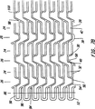
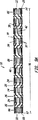
図1Aは、本発明のステントの実施態様の拡張前モードの側面図である。
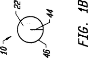
図1Bは、本発明のステントの実施態様の断面図である。
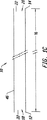
図1Cは、本発明のステントの実施態様の縦断面図である。
図2Aは、本発明のステントの実施態様のストラットパターンのスケール図である。
図2Bは、図2Aのパターン部分の拡大図である。
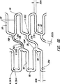
図3Aは、本発明のステントの実施態様の拡張前モードの概略図である。
図3Bは、本発明のステントの実施態様の拡張後モードの概略図である。
図4Aは、本発明のステントの実施態様の寸法を含むスケール図である。
図4Bは、図4Aのスケール図の拡大部分である。
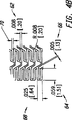
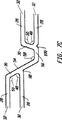
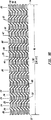
図5は、拡張後モードにおけるテーパーがつけられた直径を有する本発明のステントの実施態様のスケール図である。
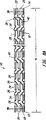
図6Aは、補強拡張コラムを備えた本発明のステントの実施態様のスケール図である。
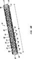
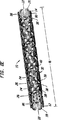
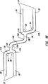
図6Bは、図6Aの実施態様の斜視図である。
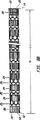
図7Aは、接合部の可撓性を増大させるため、ストラット接合部に設けたリリーフノッチを含む本発明のステントの実施態様のスケール図である。
図7Bは、図7Aの実施態様の拡大領域である。
図7Cは、図7Aの実施態様にしたがった2つの拡張ストラット対を結合する単一の連結ストラットの拡大図である。
図8Aは、本発明のステントの1実施形態の側面図である。
図8Bは、本発明のステントの1実施形態の側面図であり、ステントストラットとストラット間の空間とが透明であるかのように示されている。
図8Cは、本発明のストラットの1実施形態のスケール図である。
図8Dは、図8Cのストラットの実施形態の変形例である。
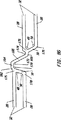
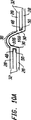
図8Eは、図8Dの実施形態の斜視図である。
図8Fは、本発明の図8Dの実施形態のストラットの拡張後の状態を示す図面である。
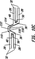
図8Gは、本発明の実施形態による、2つの拡張ストラット対を結合する単一連結ストラットの拡大図である。
図9Aは、本発明の1実施形態の側面図である。
図9Bは、図9Aの実施形態の斜視図である。
図9Cは、図9Aの実施形態のスケール図である。
図9Dは、図9Cの拡大領域である。
図9Eは、本発明のストラットの1実施形態のスケール図である。
図9Fは、本発明のストラットの1実施形態のスケール図である。
図9Gは、本発明の1実施形態による、2つの拡張ストラット対を結合する単一連結ストラットの拡大図である。
図10Aは、本発明にしたがった連結ストラットと結合ストラットの別の幾何学的配置の図面である。
図10Bは、本発明にしたがった連結ストラットと結合ストラットの他の幾何学的配置の図面である。
図10Cは、本発明にしたがった連結ストラットと結合ストラットの他の幾何学的配置の図面である。
図10Dは、本発明にしたがった連結ストラットと結合ストラットの他の幾何学的配置の図面である。
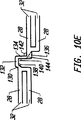
図10Eは、本発明にしたがった連結ストラットと結合ストラットの他の幾何学的配置の図面である。
図10Fは、本発明による、連結ストラットと結合ストラットとの他のジメオトリ(幾何学的配置)の図面である。
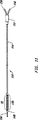
図11は、本発明にしたがったステントのデリバリー方法を示すデリバリーバルーンカテーテルである。
詳細な説明
本発明の第1の実施態様が、図1A、図1B、図1C、図2Aおよび図2Bに示されている。図1Aを参照すると、拡張していない状態における細長く、中空の管状ステント10が図示されている。近位端12と遠位端14がステント10の長手方向長さを決定している。ステント10の長手方向長さは100mm以上とすることができる。近位開口18と遠位開口20がステント10の内腔22に接続する。ステント10は、シームまたは溶接継ぎ手のない単一ピースでも、複数のピースを含んでいてもよい。
ステント10は、介在連結ストラットコラム26により、互いに連結された2ないし50の拡張コラムすなわちリング24よって作られている。近位端12上の第1のコラムおよび遠位端14上の最後のコラムは拡張コラム24である。
拡張コラム24は一連の拡張ストラット28および結合ストラット30から形成されている。拡張ストラット28は、ステント10の長手軸線の方向に、少なくとも一部が延びるように配置された薄く、細長い部材である。膨張バルーンあるいは他の手段により、内部から、ステント10に外向きの外力が加わると、拡張ストラット28は、さらに周方向に延びるように、すなわち、円筒状ステント10の表面に沿い、その長手軸線に直行して、延びるように、再指向される。拡張ストラット28が再指向されることにより、ステント10は拡張した周囲と直径を有することになる。図1Aにおいて、拡張していないステント10の拡張ストラット28は、ステント10の長手軸線にほぼ平行に延びるように見える。
拡張ストラット28は、結合ストラット30により、互いに結合され、複数の拡張ストラット対32を形成する。拡張ストラット対は、閉じた端部34と開放された端部36を有している。別の結合ストラット30は、隣接する拡張ストラット対32の拡張ストラット28を、拡張ストラット28が隣接する拡張ストラット28に、近位端と遠位端で、交互に結合されて、拡張コラム24を形成するように、互いに結合する。各拡張コラム24は複数、典型的には、8ないし12、12ないし16あるいはそれ以上の拡張ストラット28を有している。拡張コラムは、ステント10の円周の周りに延びる、連続的な途切れていないリング構造であるのが好ましいが、個々のストラットまたはストラットピースが、連続拡張コラム24から取り除かれた途切れた構造を使用してもよい。
連結ストラット38は、隣接する拡張コラム24を連結し、それぞれステント10の周囲に延びている一連の介在連結ストラットコラム26を形成する。各連結ストラット38は、拡張コラム24内の一対の拡張ストラット28を、隣接する拡張コラム24内の隣接する一対の拡張ストラット28に結合する。図1Aのステント10については、拡張コラム24内の拡張ストラット28の連結ストラットコラム26内の連結ストラット38に対する比は2対1である。しかしながら、この比は一般にx対1とすることができる。ここに、xは2より大きくまたは小さい数である。さらに、図1Aのステント10は、近位端の拡張コラム24で始まり、遠位端の拡張コラム24で終わるので、コラム当たり、mの拡張ストラット28を有するnの拡張コラム24があるとき、m−1の連結ストラットコラム26とn×(m−1)/2の連結ストラット38があることになる。
各拡張コラム24内の拡張ストラット28に比べて、各連結ストラットコラム26内の連結ストラット38の数が少ないため、ステント10は長手方向に可撓性を有することになる。長手方向の可撓性は、幅の狭い連結ストラットを用い、自然の血管の湾曲部を回って、通るときに、ステント10に、さらに可撓性と柔軟性を与えることにより、さらに増大させることができる。
ステント10内のストラット間のオープンスペースの少なくとも一部は非対称セルスペース40を形成している。セルスペースは、拡張ストラット28、連結ストラット38あるいは結合ストラット30を含むステントストラットの1つまたはこれらの組み合わせによって囲まれたステント10の表面上の空の領域である。非対称セルスペース40は、幾何学的な対称性を有さない、すなわち、回転、反転、回転と反転の組み合わせあるいはその他の対称性を有していないセルスペースである。非対称なセルスペース40は、非対称な幾何学的形状を有している。
図1Aの非対称セルスペース40は、第1の拡張コラム24内の拡張ストラット対32、第1の連結ストラット38、隣接する拡張コラム24内の第2の拡張ストラット対32、第1の結合ストラット30、第2の連結ストラット38および第2の結合ストラット30により取り囲まれている。さらに、非対称セルスペース40の拡張ストラット対32は周方向のオフセットしていてもよく、すなわち、同一直線状にない長手軸線を有し、対向する開放端部36を有していてもよい。拡張ストラット対32の2つの拡張ストラット間のスペースは、ループスロット42として知られている。
図1Bは、ステント10の内腔22、半径44およびステント壁46を示している。ステント壁46は、拡張ストラット28、連結ストラット38および結合ストラット30を含むステントストラットからなっている。
図1Cは、近位端12、遠位端14、長手方向長さ16、内腔22、ステント10のステント壁46を示している。内腔22は、ステント10の円筒表面を形成するステント壁46により取り囲まれている。
図2Aおよび図2Bを参照すると、ステント10の結合ストラット30が、拡張ストラット28と角度をなして延び、拡張ストラット対32の一方の拡張ストラット28との間に狭い角度48を、拡張ストラット対32の他方の拡張ストラット28との間に広い角度50をなしていることがわかる。狭い角度48は90度未満であり、広い角度50は90度を越えている。結合ストラット30は、ステント10の長手軸線に沿って、長手方向に、また、長手軸線に垂直なステント10の表面に沿って、周方向に、延びている。
ある拡張コラム24内の隣接する拡張ストラット28の間の拡張ストラットスペース52は、図2Aおよび図2Bのステント10内では均一である。しかしながら、均一でないスペースもまた使用することができる。拡張ストラットスペース52は変化させることができ、たとえば、拡張コラム24内の隣接する拡張ストラット28の間のスペースは狭いスペースと広いスペースとの間で変えることができる。さらに、単一の拡張コラム24内のスペース52は、他の拡張コラム24内の他のスペース52と異なっていてもよい。
ループスロット42を形成する拡張ストラットスペース52を変化させることは、ループスロット幅を可変にする。さらに、ループスロット42の長手軸線は、隣接する拡張コラム24内のループスロット42の長手軸線と同一直線上になくてもよく、平行である必要さえない。図2Aおよび図2Bは、共線的で平行なループスロット42が隣接して形成されるように、拡張ストラット28が配置されている場合を図示しているが、非共線的で平行でないループスロット42もまた使用可能である。
さらに、ループスロット42の形状は、単一あるいは複数の拡張コラム24のループスロットの間で同一である必要はない。ループスロット42の形状は、拡張ストラット28および/またはループスロット42の境界を画定している拡張ストラット対32の拡張ストラット28を連結している結合ストラット30の向きおよび物理的な寸法を変化させることにより、変えることができる。
連結ストラット38は、ある拡張コラム24内の拡張ストラット対の遠位端を第2の拡張コラム24内の隣接する拡張ストラット対32の近位端に連結することにより、隣接する拡張コラム24を結合する。図2Aおよび図2Bの連結ストラット38は、2つの直線部分により形成され、第1の直線部分54は、その遠位端で、第2の直線部分56の近位端に結合され、第1の傾斜角58を形成している。
連結ストラット38の第1の直線部分54は、結合ストラット30が拡張ストラット28と狭い角度48をなしている点で、拡張ストラット28に結合される。第1の直線部分54は、はぼ共線的に結合ストラット30に延び、結合ストラット30の線は拡張コラム24間のスペースに続いている。第1の直線部分54の遠位端は、第2の直線部分56の近位端に結合され、傾斜角を形成している。第2の直線部分56は、その遠位端で、隣接する拡張コラム24内の結合ストラット30に連結する拡張ストラット28にほぼ平行に延びている。第2の直線部分56の遠位端は、結合ストラット30が拡張ストラット28と狭い角度48をなしている点で、拡張ストラット28に付着している。結合ストラット30は、さらに、第1の傾斜角の幅と同じでも異なっていてもよいような幅を有する第2の傾斜角を有していてもよい。
図2A及び図2Bは、ステント10の長手方向軸に関して傾斜している連結ストラット38と結合ストラット30を示しており、これらのストラットは、周方向にコラムから隣りのコラムに交番している。周方向は、傾斜したストラットがステント10の表面の周りを曲がるときの硬さに関係している。連結ストラットコラム26の連結ストラット第1直線部54の傾斜の円周方向は、隣接する連結ストラットコラム26の連結ストラット第1の直線部分54の傾斜の周方向と反対である。同様に、拡張コラム24の結合ストラット30の傾斜の周方向は、隣接する拡張コラム24の結合ストラット30の傾斜の周方向と反対である。連結ストラット38と結合ストラット30の周傾斜方向が交番しているため、デリバリ時と拡張時にステント10の軸方向のねじれまたはそり(warp)が防止される。他の交番でない傾斜方向パターンが、連結ストラット38又は結合ストラット30若しくは両者に使用可能である。
図3A及び図3Bは、本発明による非拡張時及び拡張時のステントのデザインをそれぞれ概略的に示している。このデザインは、ステント10がその長手方向軸と平行に切断されて広げら、平面に投影されて示されている。連結ストラット38は、枢軸点60で傾斜角58を形成する第1の直線部分54と第2直線部56とから構成されている。不対称なセルスペース40が、拡張ストラット対32、連結ストラット38及び結合ストラット30により形成されている。マルチインターロックの非対称セルスペース40がデザインパターンを構成している。
ストラットが拡張されたとき、図3Bに示すように、拡張ストラット対32は、円筒状ステントの長手方向軸に沿う拡張ストラット28の長さを短くさせながら、それらの開口端部36で離れるように広がる。拡張時に拡張ストラット28が長手方向に短くなるのは、結合ストラット38が長手方向に長くなるのと逆である。拡張時に傾斜角58が広がることにより、連結ストラット38は真っ直ぐになり結合された拡張ストラット対32の間の距離は長くなる。この結合された拡張ストラット対32の間の距離が長くなることにより、拡張ストラット28が長手方向に短くなることが実質的に補償されている。このように、ステントは、非拡張時及び拡張時の両方でそれぞれほぼ一定の軸方向長さを有する。
ステントが拡張されたとき、各拡張コラム24は、ストラット間のスペースを広げながら、円周方向に伸びる。拡張プロセス中に真っ直ぐになった連結ストラット38により拡張コラム24がインタロックされることにより、ステント10に大きな径方向の支持力が与えられる。拡張されたときには、ステント10の全体が、伸びた拡張コラム24及び連結ストラットコラム26の連続するチェーンメッシュとして一体となり、これが、軸方向及び径方向の両方のつぶれに耐える非対称のインターロックのセルジオメトリを形成する。ステントが拡張されたとき、ステントの剛性と疲労限度は増大する。
更に、枢軸点60での連結ストラット38が効率的に曲り且つ伸びるため、それにより、ステントの長手方向の可撓性が増大する。ステントが長手方向に曲がるためには、少なくともいくらかの連結ストラット38がそれらの接平面で強制的に曲げられる。特定の連結ストラット38の接平面は、その連結ストラット38でステントの円筒表面にほぼ接する面である。連結ストラット38の幅は、一般的には厚みの2から4倍又はそれ以上であり、それにより、連結ストラット38が接平面で曲がるとき比較的に可撓性が小さくなる。しかしながら、連結ストラット38の枢軸点60により、連結ストラット38がその周りで容易に曲がるための可撓性のある結合点となり、これによりステントの長手方向の可撓性が増大する。
図4A及び図4Bには、本発明のステント10の第1実施形態の変形例が示されている。この変形例においては、ステント10は、33.25mmの長さ16及びクリンプされず且つ拡張されていない5.26mmの円周88を有する。15個の拡張コラム24は、連結ストラットコラム26とともに散在している。各拡張コラム24は、6個のストラット対32を形成する結合ストラット30によりそれらの近位端と遠位端とで交番して結合されている12個の拡張ストラット28により構成されている。拡張ストラット28は、円筒状のステント10の長手方向軸に対して平行に配列されている。結合ストラット30は、拡張ストラット対32の各々と狭い角度48と広い角度50を形成する。隣接する拡張コラム24は、周方向の傾斜方向が交番する結合ストラット30を使用している。
この第1実施形態の変形例では、拡張ストラットの幅62は20mmであり、拡張ストラットの長さ64は1.51mmであり、さらに、連結ストラットの幅66は0.13mmである。同じ拡張コラム24の第1拡張ストラット28の外側端から第2の隣接する拡張ストラット28の外側端までの距離68は064mmであり、024mmであるループスロットの幅70を残している。
第1実施形態の変形例では、連結ストラット38は、傾斜角58で第2直線部56に結合されている傾斜した第1直線部54から構成されている。第1直線部54は、第2直線部56より少し長く、さらに、拡張コラム24の拡張ストラット28に対してその近位端で取り付けられている。第1直線部54の近位端の拡張ストラット28への取付点は、結合ストラット30と拡張ストラット28との角度48が狭くなる部分である。第1直線部54は結合ストラット30に対してほぼ同一直線上で延びており、傾斜角58を形成するようにその遠位点が第2直線部56の近位端に取り付けられている。第2直線部56は拡張ストラット28に対してほぼ同一直線上で延びており、その遠位点が隣接の拡張コラム24の拡張ストラット28に取り付けられている。この取り付けは、拡張ストラット28が結合ストラット30と狭い角度48を形成する部分で行われる。結合ストラット30及び連結ストラット第1直線部54は、コラムから隣接するコラムまで交番する周方向に傾斜している。
狭い角度48が形成されている点で連結ストラット38と拡張ストラット28が結合されているので、拡張していないステントの表面を流線形にすると共に当たる可能性のある点を少なくすることにより、ステント10のスムーズなデリバリがし易くなる。血管の目標損傷部にステント10を裸でデリバリすることにより、血管中の曲り部分を通るときに突き刺さったり当たったりすることが最小限となる。ステント10は、デリバリ用カテーテル上で血管内で前後方向に移動するとき、可撓性のあるチューブ状のそりのように挙動し、蛇行した血管内及び血管壁の内側のアステローム硬化症のプラークにより生じた不規則な出っ張り上を滑る。
図4A及び図4Bに示す十分に拡張されたステント10は最大5.0mmまでの初期直径を有し、一方、許容できる半径方向強さ及び疲労限度を保持している。クリンプ(crimped)されたステントの外径は、下にあるデリバリ用バルーンプロフィールの状態により1.0mm程度に小さいか又はそれ以下である。クリンプされたステントの外径が小さいということは、目標部位を予め拡張することなしにステントをデリバリする場合には重要である。ステントがオプションとしてデリバリ用バルーン上でクリンプされたときには、クリンプされたステントの表面は、血管内を前後に移動するときステントストラットが突き刺さったりすることがないように、滑らかである。
図5は本発明の第2実施形態を示し、この第2実施形態では、拡張された形態のステント10では、近位端12から遠位端14まで徐々に傾斜している。拡張ストラット28の影が付けられたセグメント72,74,76,78,80,82,84は、取り外されるべき拡張ストラット28の領域を示している。影が付けられたセグメント72,74,76,78,80,82,84を取り外すことにより、ステント10は、近位端12よりも小さな拡張された直径を持つ遠位端とと共に拡張されてときには、徐々に傾斜する。所定の拡張コラム24でステント10の拡張された直径を短くする程度は、拡張コラム24の取り外されたセグメント72,74,76,78,80,82,84の長さに比例する。拡張されたステント10において、短くなった拡張ストラット28は、円周と直径が短くなるようなステントの環境に沿って短くなったコンポーネントを有する。傾斜した直径部分は、ステント10の長さに沿ってどこでも配置可能であり、さらに、所定の拡張コラム24の拡張ストラット28の適当に大きいか又は小さい部分を取り除くことによりほぼ徐々に傾斜する。血管の傾斜は長くなるほど明らかになるため、12mmより長いステントにおいて特に重要である。均一なステント直径を持つ長いステントは、短い領域上でのみ目標血管直径に対して一致させることができる。近位の血管寸法がステント直径と一致する場合には、ステントの拡張された直径は、自然な血管には大きすぎることになり、さらに、ステントの拡張により遠位血管の初期切開が必要となる可能性がある。一方、遠位血管の寸法がステントの直径と一致すれば、拡張されたステントの近位端は、血管壁の内側にセットするには小さすぎることになる。
テーパ拡張ステントを達成する別の仕方は、ストラットの剛性がステントの長さに沿って変化するように、ステントストラット、拡張ストラット、連結ストラット又は結合ストラットの剛性を変えることにある。ストラットの剛性は、長さ、幅、厚さを変更すること、追加の剛性材料を追加すること、化学的又は機械的手段を用いてステント材料の物理的特性を変更すること、または、ステントに一つ又は一連のエラスティック要素をつけることによって変えることができる。
テーパ直径ステントの使用に加え、かかるテーパ直径ステントをデリバリ及び配置することができるように、適合したテーパバルーンカテーテルを作るのが理想である。テーパ直径ステントに関してテーパ適合バルーンカテーテルを使用する方法は本発明の範囲内にある。
テーパバルーンを使用して非テーパステントを拡張させることもまた、テーパ拡張ステントを達成することになる。しかしながら、金属をステントから取り除くことはできないので、ステントは不完全な拡張の結果としてテーパする。従って、ステントはテーパ端において金属の割合を増大させることになり、このことは、急性血栓症の危険を高めてしまうことになる。金属の割合は、ステントストラット材料によって被覆された拡張ステントの表面の比率である。図5に示すように拡張ストラットを短縮することにより、テーパステントはその長さに沿って金属の割合を実質的に一定にすることができる。
図6A及び図6Bに示す本発明の第3実施形態が、ステント10の長さに沿って配置された多式強化拡張コラム86を有する。これらの強化コラム86は、ステント10に追加の局部的な半径方向強度及び剛性を与えるため、ステントの長さに沿って配置される。追加の強度及び剛性は、ステントの変形をデリバリ中及び配置後の両方において防止するため、ステントの端において特に重要である。デリバリ中、ステントの端は血管壁をひっかけてしまうことがあり、拡張されていないステントを変形させ、ステントの拡張特性を変えてしまうかもしれない。ステントを配置した後には、ステントの端が血管壁に堅固に当接して配置されるようにステントの端を固定することが重要である。さもなければ、引き続くカテーテル作業中、カテーテル又はガイドワイヤがステントの端をひっかけて、ステントを血管壁から離れるように引っ張り、血管を傷つけてしまい、及び又は、血管を遮断してしまうことがある。
図6A及び図6Bに示すステント10の第3実施形態の特定例は、20.70mmの長さ16と、5.26mmの、クリンプされても、拡張されてもいない円周88とを有する。ステント10は、6つの拡張コラム24と、3つの強化拡張コラム86とを有し、各コラムは、夫々、12の拡張ストラット28、強化拡張ストラット90を有する。強化拡張コラム86は、ステント10の各端に1つ、ステント10の長さに沿って1つ位置決めされている。
拡張ストラットの幅62は0.15mmであり、強化拡張ストラットの幅92は0.20mmであり、連結ストラットの幅66は0.10mmである。結合ストラット30及び拡張ストラット28によって形成された狭角48は75°であり、強化結合ストラット96及び強化拡張ストラット90によって形成された狭角94は60°である。
ステントの両端にのみ、或いは、ステントの一方端にのみ、或いは、ステントの長さ全体を通じて複数箇所に強化拡張コラム86を提供することのような強化拡張コラム86のその他の構造を用いることができ、この構造も本発明の範囲内にある。また、適当な拡張コラム24、86の拡張ストラット28、強化拡張ストラット90を短縮することによって、テーパを強化ステント10に組み込むことができる。
図7A、図7B及び図7Cに示す本発明の第4実施形態は、第3実施形態に似ているけれども、追加の特徴のリリースノッチ98、100を有する。リリースノッチは、金属がストラットから取り除かれた場所、通常、複数のストラットが連結される結合部にあるノッチである。リリースノッチ98は、連結ストラット38の第1直線部分54と、拡張ストラット28との間に形成された結合部に形成されている。リリースノッチ100は、連結ストラット38の第2直線部分56と、拡張ストラット28との間に形成された結合部に形成されている。リリースノッチの位置決めは、拡張されていないステントに追加の可撓性を与える。リリースノッチは、その他の結合部に設けることができ、上述したいずれの実施形態にも含めることができる。
図8A及び図8Bは、本発明のステントの第5の実施形態の変形例の側面図である。この実施形態では、4ピース傾斜連結ストラット38が使用され、一つの拡張コラム24の拡張ストラット対32の角を、隣接する拡張コラム24の円周方向のオフセットされた拡張ストラット対32の結合ストラット30に連結している。拡張ストラット28と、結合ストラット30と、拡張コラム24と、補強拡張ストラット90と、補強結合ストラット96と、補強拡張コラム86は、図6Aの第4の実施形態とほぼ同じである。しかしながら、連結ストラットコラム26の連結ストラット38は、後述するように、ジオメトリ(幾何学的配置)と連結とが変更されている。
図8Aは、ステント表面の前半分のステントストラットのみを示している。ステント表面の裏半分は図示しない。ステントは、ステントストラットとその間の空間とが不透明であるかのように、表わされている。図8Bは、前半分および後半分の両方から全てのステントストラットを示している。ステントは、ストラットとその間の空間とが透明であるかのように、表されている。
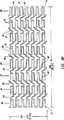
図8Cに示されている本発明の第5の実施形態の第1の変形例は、12の拡張コラム24と、4つの補強拡張コラム86と、15の連結ストラットコラム26とを備えたステント10からなっている。この変形例では、ステント10は、長さ16が、31.96mmであり、非拡張状態の円周88が5.26mmである。
図8Gに拡大して示されている連結ストラット38は、4つの直線部分、すなわち、3つの傾斜角170、172、174をなしている、近位端部分162と、第1の中間部分164と、第2の中間部分166と、遠位端部分168とを備えている。近位端部分162の近位端は、拡張コラム24の拡張ストラット対32の角176に取付けられている。角176は、結合ストラット30が拡張ストラット28と狭い角度48をなしているところに形成されている。拡張ストラット32の第2の角178は、結合ストラット30が拡張ストラット28と広い角度50をなしているところに形成されている。角176、178は、直線拡張ストラット28と結合ストラット30を結合することにより形成される傾斜形状を有することができ、または、角176、178を丸めて、鋭い角を取り除き大きな可撓性を提供するのが好ましい。さらに、丸められた角により、ステント10は、より大きく拡張でき、かつ、拡張したとき、角のステントストラット材料の応力を減少させる。
連結ストラット38の近位端部分162は、角176から延び、その遠位端が、傾斜角170をなして、第1の中間部分164に取付けられている。第1の中間部分164は、第1の中間部分164が拡張ストラット28と平行であるように、近位端部分162から延び、その遠位端が、傾斜角172をなして第2の中間部分166の近位端に連結されている。
第2の中間部分166は、ステント10の長手方向軸線に対して傾斜して延びて、ステント10に沿って長手方向に且つステント10を中心に円周方向に延びている。第2の中間部分166は、隣接する拡張コラム24の円周方向にオフセットした拡張ステント対23の結合ステント30と平行であるのが好ましい。
第2の中間部分166は、遠位端が、傾斜角174をなして、遠位端部分168の近位端に取付けられている。遠位端部分168は、第2の中間部分166から延び、その遠位端が、隣接する拡張コラム24の円周方向にオフセットした拡張ストラット対32の結合ストラット30に取付けられている。取付けは、角176、178の間の点であり、結合ストラット30は、拡張ストラット28と、狭い角度48と広い角度50を、それぞれ、なしている。
遠位端部分168の結合ストラット30への連結点は、角178より角176に近い。連結点は、角176から、1ないし2またはそれより大きい拡張ストラット幅であるのが好ましい。遠位端部分168の結合ストラット30への連結点を、角176から角176と角178の間へオフセットさせることにより、拡張ステント10のそりまたはねじれ(warp)が減少し、滑らかな表面変動(modulation)が得られ、血栓症の危険が減少する。加えて、この設計により、連結ストラット38のより長い総直線長が得られ、これにより、拡張中にステント10の短縮が、減少する。
図8D、図8Eに非拡張形態が、図8Fに拡張形態が示されている、本発明の第5の実施形態の第2の変形例は、6つの拡張コラム24と、2つの補強拡張コラム86と、7つの連結コラム26とを備えたステント10からなる。この変形例では、ステント10は、長さ16は、15.04mmであり、非拡張の円周88が5.26mmである。ステント10の設計は、拡張コラム、補強拡張コラムおよび連結ストラットコラムの数が少ない図8Cの第5の実施形態の第1の変形例の設計とほぼ同じである。
図8Fは、第5の実施形態の第2の変形例の拡張したステント10の一部分を示している。バルーンまたは他の手段でステント10を拡張した後には、拡張ストラット28は、円周方向に離れて拡げられており、拡張ストラット対32の開放端36での分離が増加し、その結果、ステント10の円周が増大している。拡張ストラット28を拡げると、拡張コラム24の長手方向収縮がおこり、これが、連結ストラット38が真っ直ぐになること(直線化)によって、補償される。拡張工程の間に、傾斜角170、172および174が広くなり、連結ストラット38を真っ直ぐにし、隣接する拡張コラム24の間の分離距離を大きくする。拡張ストラットの非対称連結セルの幾何学的配置を図8Fに示す。
図9A、図9B、図9C、図9D、図9E、図9F、および、図9Gは、本発明のステントの第6の実施形態を示す。この実施形態では、3ピース傾斜連結ストラット38が、一つの拡張コラム24の拡張ストラット対32の結合ストラット30を隣接する拡張コラム24の円周方向にオフセットした拡張ストラット対32の結合ストラット30に連結するために、使用されている。連結ストラット38の各部分間の接合部は、滑らかな丸められた形状をなして、湾曲している。拡張ストラット28と、結合ストラット30と、拡張コラム24と、補強拡張ストラット90と、補強結合ストラット96と、補強拡張コラム86は、図8Aの第4の実施形態とほぼ同じである。しかしながら、連結ストラットコラム26の連結ストラット38は、後述するように、ジオメトリ(幾何学的配置)と連結とが変更されている。
図9A、図9B、および、図9Cに示される本発明の第6の実施形態の第1の変形例は、8つの拡張コラム24と、3つの補強拡張コラム86と、10の連結ストラットコラム26とを備えたステント10からなる。この変形例では、ステント10は、長さ10が20.32mmである。
リリーフノッチ204が、ステントの近位端12と遠位端14の補強拡張コラム86の補強拡張ストラット90と補強結合ストラット96との間の接合部に、利用されている。リリーフノッチ204は、補強拡張ストラット90と補強結合ストラット96との間の接合部の幅を減少させ、ストラット拡張中および拡張後の接合部での金属の応力を減少させる。ステントの端は拡張中および拡張後に特にそり又はねじれ(warp)を受けやすいので、リリーフノッチ204はステントの端で特に重要である。リリーフノッチ204は、接合幅を減少させ、接合幅は、ステント壁46の厚さとほぼ同じである(図1B、図1C参照)。
図9Dに拡大して示されている連結ストラット38は3つの直線部分、即ち、傾斜角200、202をなしている遠位端部分194と中間部分196と近位端部分198と備えている。連結ストラット38は、連結ストラットの各部分194、196、198の間に、広い半径の湾曲を有している。したがって、連結ストラット38の形状は、鋭い角度で折り曲げられているのでなく、湾曲あるいは波打っている。傾斜角200、202は、図9Dに示されているように、直線的に延びている近位端部分194、中間部分196、および、遠位端部分198によって、形成されている。
図9Eは、本発明の第6の実施形態の連結ストラットの設計の変形例を示している。図9Eに示されている連結ストラット38は、近位端部分194、中間部分196および遠位端部分198の間の接合部で、小さな半径の湾曲を有している。従って、図9Eの連結ストラット38は、図9Dの連結ストラットより、鋭い角度で折り曲げられている。
図9Dおよび図9Eの連結ストラット38を参照すると、近位端部分194の近位端は、角176、178の間で、拡張ストラット対32の結合ストラット30に取付けられている。連結ストラット38の近位端部分194は、結合ストラット30から延び、その遠位端が、傾斜角200をなして、中間部分196に取付けられている。中間部分196は、ステント10の長手方向軸線に対して傾斜した向きで、近位端部分194から延び、ステント10に沿って長手方向に且つステント10を中心に円周方向に延びている。中間部分196は、連結された拡張ステント対32の結合ストラット30と平行であるのが好ましい。
中間部分196は、その遠位端が、傾斜角202をなして、遠位端部分198の近位端に連結されている。遠位端部分198は、第2の中間部分196から延び、その遠位端が、隣接する拡張コラム24の円周方向にオフセットした拡張ストラット対32の結合ストラット30に取付けられている。取付けは、角176、178の間であり、そこで、結合ストラット30は、拡張ストラット28に対して、狭い角度48と広い角度50を、それぞれ、なしている。
近位端部分194および遠位端部分198の、結合ストラット30への連結点は、角178より角176に近い。連結点は、角176から、1ないし2又はそれより大きい拡張ストラット幅であるのが好ましい。遠位端部分198の結合ストラット30への連結点を、角176から角176と角178の間にオフセットさせることにより、ステント10のそり又はねじれ(warp)が減少し、滑らかな表面変動(modulation)が得られ、血栓症の危険が減少する。加えて、この設計により、連結ストラット38のより長い総直線長が得られ、これにより、拡張中にストラットの短縮が、減少する。
第6の実施形態の連結ストラット38は、その中心の周りで、180度の回転対称である。しかしながら、各セルスペースで連結されたループスロット42が異なっているので、ストラット38の対称性は対称的なセルスペースをもたらさない。各拡張コラムの隣接するスープスロット42が、交互に狭い幅と広い幅とを有し、セルスペースが対称にならないようにしている。1または多くの対称セルスースを導入することは、この設計では、例えば、同じセルスペースに収容された隣接する拡張コラム24のループスロットに、均一なループスロット幅を提供することによって、達成される。加えて、対称または非対称なセルスペースを利用する完全に不均一なセルスペースは、例えば、ループスロット42の幅の不均一に変化させることによって、達成される。
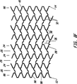
図9Fに非拡張形態で示されている本発明の第6の実施形態の第2の変形例は、6つの拡張コラム24と、3つの補強拡張コラム86と、8つの連結ストラットコラム26とを備えているステント10からなっている。この変形例では、ステント10は、長さ16が、16.00mmであり、非拡張状態の円周88が5.26mmである。このステント10は、拡張コラム24と連結ストラットコラム26の数が少ない図9A、図9Bおよび図9Cの第6の実施形態の第1の変形例の設計とほぼ同じである。
図9Fに非拡張状態で示されている、本発明の第6の実施形態の第3の変形例は、12の拡張コラム24と、4つの補強拡張コラム86と、15の連結ストラットコラム26とを備えているステント10からなる。この変形例では、ステント10は、長さ16が、30.01mmであり、非拡張状態の円周88が5.26mmである。このステント10は、拡張コラム24と補強拡張コラム86と連結ストラットコラム26の数が多い図9A、図9Bおよび図9Cの第6の実施形態の第1の変形例の設計とほぼ同じである。
図10A、図10B及び図10Cは、変形例の連結ストラットの設計の幾つかの例を示し、これらの設計は、上述したいずれの実施形態にも使用することができる。図10Aは丸みのついたループ状の連結ストラット38を示し、このストラット38は、隣接した拡張コラムの円周方向にオフセットした、又は、ずれた2つの拡張ストラット対32を結合する。各拡張ストラット対32の拡張ストラット28が結合ストラット30によって結合される。結合ストラット30は、これらの結合ストラット30が連結する拡張ストラット28と共に狭角48及び広角50を形成するように、傾斜されている。丸みのついたループ状の連結ストラット38は、拡張ストラット28と結合ストラット30との間に狭角が形成されている個所で拡張ストラット28を連結する。近位端102及び遠位端104の丸みのついた連結ストラット38の傾斜は、対の拡張ストラット28を連結する結合ストラット30の傾斜に実質的に合致する。かくして、丸みのついたループ状の連結ストラット38は、結合ストラット30に滑らかに移行する。更に、丸みのついたループ状の連結ストラット38は、第1の曲率半径106と、第2の曲率半径108とを有する。
図10Bの設計では、丸みのついたループ状の連結ストラット38が、隣接した拡張コラムの円周方向にオフセットした2つの拡張ストラット対32を結合する。各拡張ストラット対32の拡張ストラット28は結合ストラット30によって結合される。結合ストラット30は、これらの結合ストラット30が連結する拡張ストラット28に対して直角である。丸みのついたループ状の連結ストラット38は、結合ストラット30と同じ個所で拡張ストラット28に連結する。丸みのついたループ状の連結ストラット38は、第1の曲率半径106と、第2の曲率半径108とを有し、連結ストラット38は、円周方向にオフセットした拡張ストラット対32を連結する。
図10Cの設計では、連結ストラット38は、隣接した拡張コラムの円周方向にオフセットした2つの拡張ストラット対32を結合する。各拡張ストラット対32の拡張ストラット28は結合ストラット30によって結合される。結合ストラット30は、これらの結合ストラット30が連結する拡張ストラット28と共に狭角48及び広角50を形成するように、傾斜されている。連結ストラット38は、拡張ストラット28と結合ストラット30との間に狭角48が形成される個所で拡張ストラット28を連結する。
連結ストラット38は3つの直線部分110、112、114で作られ、これらの直線部分110、112、114は2つの傾斜角116、118を形成する。部分110の近位端は、結合ストラット30が拡張ストラット28と共に狭角48を形成する個所で拡張ストラット28に取り付けられる。連結する部分110は、結合ストラット30と実質的に同一線上に延び、遠位端が部分112に取り付けられて、傾斜角116を形成する。部分112は、該部分112が拡張ストラット28と実質的に平行になるように部分110に対して或る角度に延び、遠位端が部分114の近位端に連結されて傾斜角118を形成する。部分114は、該部分114が隣接した拡張ストラット対32の結合ストラット30と実質的に同一線上にあるように、或る角度に延びる。部分114は、結合ストラット30が拡張ストラット28と共に狭角48を形成する個所で、部分114の遠位端が隣接した拡張ストラット対32の拡張ストラット28につく。
図10D及び図10Eの設計では、連結ストラット38は、隣接した拡張コラムの円周方向にオフセットした2つの拡張ストラット対32を結合する。各拡張ストラット対32の拡張ストラット28は結合ストラット30によって結合される。結合ストラット30は、これらの結合ストラット30が連結する拡張ストラット28に対して直角である。連結ストラット38は、結合ストラット30と同じ個所で拡張ストラット28に連結する。
図10D及び図10Eの連結ストラット38は端と端とが連結された複連結ストラット部分で作られて、拡張ストラット対32を隣接した拡張ストラット対32に連結する複傾斜角度を持ったギザギザの連結ストラット38を形成する。図10Dの連結ストラット38は、2つの傾斜角126、128を備えた3つの連結ストラット部分120、122、124で作られているのに対して、図10Eの連結ストラットは、3つの傾斜角138、140、142を備えた4つの連結ストラット部分130、132、134、136で作られている。更に、連結ストラット部分136を点線又は破線がつけられた連結ストラット部分144と置換することによって連結ストラット部分134を改良し、別の可能な幾何学形状の連結ストラット38を与えることができる。
図10Fの設計では、連結ストラット38が、2つの円周方向にオフセットした拡張ストラット対32を、隣接する拡張コラム内で、結合している。各拡張ストラット対32の拡張ストラット28は、結合ストラット30によって、結合されている。結合ストラット30は、接触している拡張ストラット28と狭い角度48と広い角度50をなすように傾斜させられている。
結合ストラット38は、4つの直線部分、すなわち、3つの傾斜角188、190および192を形成している、近位端部分180と、第1の中間部分182、第2の中間部分184と、遠位端部分186とを備えている。部分180の近位端は、結合ストラット30が拡張ストラット28と狭い角度48をなしている点で、角(曲がり角)176に取付けられている。近位端部分180は、ある角度で、結合ストラット30まで延びており、その遠位端が、傾斜角188を形成する第1の中間部分182に取付けられている。第1の中間部分182は、第1の中間部分182が拡張ストラット28とほぼ平行になるように、ある角度で近位端部分180まで延び、その遠位端が、傾斜角190を形成する第2の中間部分184の近位端に連結されている。第2の中間部分184は、第1の中間部分182より、かなり長い。第2の中間部分184は、隣接するストラット対32の結合ストラット30とほぼ平行であるように、ある角度で延びている。第2の中間部分184は、その遠位端が、傾斜角192を形成する遠位端部分186の近位端に取付けられている。遠位端部分186は、拡張ストラット28に対して僅かに傾斜した配向で延びており、結合ストラット30が拡張ストラット28と狭い角度48を形成している拡張ストラット対32の角176に取付けられている。リリーフノッチ206が、連結ストラット38の遠位端部分186と拡張ストラット対32の角176との間の接合部に、形成され、非膨張ステントの可撓性を増大させ、ステントが拡張させられたときに、反らないようにしている。
当業者は、本発明による連結ストラット及び結合ストラットについて多くの構成を取ることができることを理解するであろう。上述した例は網羅的なリストとして意図されてはいない。特に、(a)連結ストラット部分は直線である必要はなく、1または2以上の湾曲の半径を含んでいるものでもよく、(b)連結ストラット部分は、各々が、異なった長手方向軸線を有していてもよく、(c)連結ストラット部分間の接合部は、切れ込みを入れられ又は鋭い必要はなく、1または2以上の湾曲の半径を含んで滑らかであってもよく、(d)リリーフノッチが、いずれのストラット接合部にあってもよいことに留意すべきである。
本発明のステントは原則的には冠状血管への適用に適しているけれども、このステントの多機能性により非冠状血管、大動脈及び非脈管の管状の身体器官に適用することができる。
代表的な冠状脈管ステントは、2.5mm乃至5.0mmの拡張径を有する。しかしながら、高い半径方向強度及び疲労耐久性を備えた、5.0mmまで拡張するステントは、より小さな直径の血管に用いられるときに、許容することができないステントの高い金属割合を有してしまうかもしれない。ステントの金属割合が高いときには、急性血栓症の恐れ及び再狭窄の潜在性が高まることになる。同じ金属割合の場合でさえ、管腔直径の小さな血管は、管腔直径の大きな血管よりも、血栓症の率が高くなりそうである。従って、冠状への適用のため、少なくとも2つの異なる種類のステント、例えば、2.5mm乃至3.0mmの直径の血管用の小血管ステントと、3.0mm乃至5.0mmの直径の血管用の大血管ステントとを有することが好ましい。かくして、小血管及び大血管の両方は、適当な寸法のステントで処理されたときに、同様に理想化された金属割合のステントを収容することになる。
本発明のステントは、ステンレス鋼管からステントパターンを切断するCAM駆動レーザ切断システムを用いて作ることができる。荒切りステントを電解研磨して表面の凹凸や鋭いエッジを除去するのが好ましい。EMD、光電エッチング技術、或いはその他の方法のようなステントを作る他の方法を用いることもできる。必要な構造強度、可撓性、生体適合性および拡張性を提供するかぎり、その他の金属およびポリマーを含むステントのための任意の材料を使用することができる。
スレントは代表的には、金、プラチナ、或いはその他の適当な金属のようなX線不透過性の金属で少なくとも部分的にめっきされている。局所的めっき加工によってステントの両端だけをめっきすることが好ましい。しかしながら、ステント全体、或いはその他の領域もめっきしてよい。両端をめっきするときには、ステントの各端上の1つから3つまたはそれ以上の拡張コラムをめっきしステントの両端をマーキングして、ステントの両端が、ステント設置手順中X線透視により同定されることができるようにする。両端においてのみステントをめっきすることによって、X線不透過性めっき材料とステントの性能特性または表面変調との干渉が最小にされる。さらに、必要とされるめっき材料の量が減らされ、それによって、ステントの材料費が安くされる。
めっき加工後、ステントを、代表的には当業界でよく知られた洗剤、塩水および超音波装置で洗浄する。次いで、ステントを、品質管理のために検査し、デリバリバルーンカテーテルに組み付け、正しく包装し、ラベル付けし、殺菌する。
ステントは、単独で、或いは、図9に示されているように予め取り付けられたデリバリバルーンカテーテル組立体として市場に出すことができる。図9を参照すると、ステント10は、デリバリバルーンカテーテル150の遠位端148の折り畳まれたバルーン146上にクリンプされている。組立体150は、近位端アダプタ152と、カテーテルシャフト154と、バルーンチャンネル156と、ガイドワイヤチャンネン158と、ガイドワイヤ160と、を含む。バルーン146は、膨張された状態において近位端から先細にされているか、湾曲されているか、或いは先細にされかつ湾曲されているのがよい。さらに、ステント10は、拡張された状態において先細にされていなくて先細にされていてもよい。
代表的には、ガイドワイヤ160を静脈または動脈に挿入し、目的部位まで前進させる。所定位置に置いたならば、バルーンチャンネル156を通じてバルーン146を膨張させて、ステント10をクリンプされた状態から拡張された状態に拡張する。拡張された状態では、ステント10は、所望の骨格結合支持を血管に提供する。ステント10を拡張した後は、バルーン146を萎ませ、カテーテルシャフト154、バルーン146およびガイドワイヤ160を患者から引っ込める。
本発明のステントは、長さが10mmよりも短く、或いは、100mm以上に作ることができる。しかしながら、長いステントを使用しようとする場合には、ステントをその配置位置に拡張するためには、適合した長さのデリバリカテーテルバルーンが代表的には必要とされる。長いステントは、目的血管によっては、配置のために湾曲した長いバルーンを必要とすることがある。血管の自然の湾曲に適合した湾曲されたバルーンは、ステント配置中血管へのストレスを減少させる。これは、湾曲された冠状血管におけるステント配置が必要となる多くの冠状血管への適用において特に重要である。かかる湾曲されたバルーンの使用は、本発明の範囲内にある。
本発明の好ましい実施形態のこれまでの説明は、例示と説明の目的でなされてきた。それは、用尽的なものを意図したものではなく、本発明を、開示した正確な形態に限定することを意図したものでもない。明らかに、当業者には、多くの変形および変更が明らかであろう。本発明の範囲は、以下の請求の範囲およびそれらの均等物によって画されるものである。Background of the Invention
Field of Invention
The present invention relates to intravascular stents, and more particularly to intravascular stents that can be easily introduced through tortuous portions of blood vessels.
Explanation of related technology
Coronary artery or general blood vessel angioplasty has been developed and has become the most effective means for revascularization of constricted blood vessels. In the early 1980's, angioplasty first became available for clinical practice of coronary arteries and has since proven to be an effective alternative to traditional bypass graft surgery. Balloon catheters used in angioplasty have also proven to be the most reliable and practical interventional method. Other ancillary techniques, such as laser-based therapy and directional or rotational coronary atherectomy, are limited in effectiveness or depend on balloon angioplasty to achieve the intended procedure I know. Restenosis after balloon-based angioplasty is the most serious defect and is particularly common in the coronary artery system.
A number of regimens have been devised to control restenosis, including laser-based therapy and directional or rotational coronary atherectomy, but have only limited success. However, providing a stent in the vessel significantly reduces the rate of restenosis after angioplasty. The technique of positioning a stent within a vessel typically involves pre-dilatation of the target vessel using balloon angioplasty prior to placement of the stent and dilatation of the stent so that the dilated vessel wall is exposed from the inside. It needs to be supported.
Intravascular stents serve the function of skeletal bonds for the lumen of blood vessels. The skeletal connection of the vessel wall by the stent (a) prevents the expanded vessel wall from elastically recoiling, (b) eliminates the remaining stenosis of the vessel that typically occurs in balloon angioplasty ( c) keep the diameter of the stented vessel part slightly larger than the diameter of the original unoccluded proximal and distal part of the stented part, and (d) As shown in the data, it helps to reduce the rate of restenosis. Following angioplasty, the rate of restenosis of the stented vessel was treated by other methods such as unstented vessels and other treatments including drug treatment and other methods already mentioned It has been found that it is significantly lower than
Another advantage of having a stent in a blood vessel is that it potentially reduces the urgency of bypass surgery resulting from angioplasty. Providing a stent has been found effective in some cases to treat the impending closure of blood vessels during angioplasty. Providing a stent can control and stabilize the unstable local intimal rupture of the blood vessels caused by normal procedures during angioplasty. In some cases, incomplete or suboptimal expansion of vascular lesion tissue by balloon angioplasty can be successfully opened using a stent-graft.
In the early stages of development, the practical application of stents, particularly in coronary arteries, had serious anticoagulant problems. However, since then anticoagulant technology has developed and is now simple and effective. Better and easier regimens, including out-of-patient anticoagulant therapy, are constantly being introduced and hospital stays for stent patients are shortening.
An example of a conventional stent patent is US Pat. No. 5,102,417 (hereinafter the Palmaz patent). The stent described in the Palmaz patent comprises a series of elongate tubular members having a plurality of slots disposed substantially parallel to the longitudinal axis thereof. The tubular members are connected by at least one flexible connecting member.
The unexpanded tubular member of the Palmaz patent is overly rigid, so that the practical application range is limited to short lengths. Long stents cannot pass through tortuous blood vessels, even with a multi-link design with flexible connecting members connecting serial tubular members. Furthermore, since the tubular member that does not expand has high rigidity, there is a high risk of damaging the blood vessel during insertion. At the time of insertion, shortening the stent makes accurate positioning of the stent difficult and reduces the area that the expanded stent can cover. Furthermore, there is no way to program an expanded stent with a tapered diameter along the longitudinal axis of the stent, nor is there a way to reinforce the end or other area of the stent.
Another example of a conventional stent patent is WO96 / 03092, the Brun patent. The stent described in the Brun patent is formed by a patterned tube having first and second serpentine patterns. The even and odd first patterns are 180 degrees out of phase, and the odd pattern occurs between two even patterns. The second winding pattern runs perpendicular to the first winding pattern along the axis of the tube.
Adjacent first winding patterns are connected by a second winding pattern to form a substantially uniformly distributed pattern. The symmetrical placement of the first and second tortuous patterns with sharp right-angled bends allows for capture and obstruction on the vessel wall during delivery. Furthermore, the large swirl in the second tortuous pattern will not be straight enough when expanded, reducing the stiffness and structural strength of the expanded stent. Furthermore, there is no way to program an expanded stent with a tapered diameter along the longitudinal axis of the stent, nor is there a way to reinforce the end or other area of the stent.
These and other conventional stent designs are, to varying degrees, (a) impossible to pass through bends in vessels due to the column stiffness of the unexpanded stent, and (b) the unexpanded stent. Lack of radial and axial structural strength, (c) large shortening of stent during expansion, (d) limited stent length, (e) constant diameter of expanded stent, (f) low crimp It has various disadvantages including properties and (g) rough surface condition of the unexpanded stent.
There is a need for a stent that has sufficient longitudinal flexibility and can pass through tortuous blood vessels in an unexpanded state. Furthermore, there is a need for a stent that has high structural strength in a non-expanded state and that has minimal risk of damage or twisting during delivery. Furthermore, there is a need for a stent that can maintain the length in the longitudinal direction substantially constant even during expansion, can cover the target site greatly, and can easily position the stent appropriately. Furthermore, there is a need to design a stent that is sufficiently flexible in the longitudinal direction that can be safely delivered through a meandering blood vessel through a long stent up to 100 mm. There is a need for a stent configured to expand to various diameters along its length to produce a taper that matches the natural taper of the target vessel. (I) strongly crimped on an inflated balloon while maintaining low profile and flexibility; (ii) has a smooth surface condition when crimped on a delivery balloon; or (iii) end There is a need for a stent having a reinforcing ring that secures the end of the stent relative to the vessel wall of the target vessel, either in the center or in the center.
Summary of invention
Accordingly, it is an object of the present invention to provide a skeleton in the lumen of a blood vessel.
Another object of the present invention is to provide a stent that prevents the recoil of blood vessels after angiogenesis.
It is another object of the present invention to provide a stent that maintains a large vessel lumen as compared to results obtained by balloon angioplasty alone.
It is still another object of the present invention to provide a stent that has a reduced stent length reduction when expanded.
Another object of the present invention is to provide a stent with increased flexibility when delivered to a selected site within a blood vessel.
Another object of the present invention is to provide a stent having a low profile when crimped onto a delivery balloon of a stent assembly.
Another object of the present invention is to provide a stent with a stent frame with less tuliping.
Another object of the present invention is to provide a chain mesh stent with reduced vessel “hang-up” in tortuous or curved vessels.
Another object of the present invention is to provide a chain mesh stent with increased expanded stent radius and axio-lateral strength.
These and other objects of the present invention are achieved with an unexpanded stent. The first expansion stent pair includes a first expansion strut positioned adjacent to the second expansion strut and a coupling that couples the first and second expansion struts at a distal end of the first expansion strut pair. Includes struts. A plurality of first expansion strut pairs form a first expansion column.
A second expansion strut pair has a first expansion strut positioned adjacent to the second expansion strut and the first and second expansion struts joined at the proximal end of the second expansion strut pair. And a second expansion stent pair of connecting struts. A plurality of second expansion strut pairs form a second expansion column.
The first connecting strut includes a first connecting strut proximal portion, a first connecting strut distal portion, and a first connecting strut intermediate portion. The first connecting strut proximal portion is connected within the first expansion column to the distal end of the first expansion strut pair, and the first connecting strut distal portion is the second expansion column second portion. Connected to the proximal end of a pair of expansion struts. A plurality of first connecting struts form a first connecting strut column that connects the first extension column to the second extension column. The length of the first connecting strut proximal portion is equal to the length of the first connecting strut distal portion, and the length of the first connecting strut intermediate portion is the first connecting strut proximal portion and the first connecting strut proximal portion. Longer than the length of the distal portion of the connecting strut.
[Brief description of the drawings]
FIG. 1A is a side view of a pre-expansion mode of an embodiment of the stent of the present invention.
FIG. 1B is a cross-sectional view of an embodiment of the stent of the present invention.
FIG. 1C is a longitudinal cross-sectional view of an embodiment of the stent of the present invention.
FIG. 2A is a scale diagram of a strut pattern of an embodiment of the stent of the present invention.
FIG. 2B is an enlarged view of the pattern portion of FIG. 2A.
FIG. 3A is a schematic view of the pre-expansion mode of the stent embodiment of the present invention.
FIG. 3B is a schematic diagram of a post-expansion mode of an embodiment of the stent of the present invention.
FIG. 4A is a scale diagram including dimensions of an embodiment of the stent of the present invention.
FIG. 4B is an enlarged portion of the scale diagram of FIG. 4A.
FIG. 5 is a scale diagram of an embodiment of a stent of the present invention having a tapered diameter in post-expansion mode.
FIG. 6A is a scale diagram of an embodiment of a stent of the present invention with a reinforced expansion column.
6B is a perspective view of the embodiment of FIG. 6A.
FIG. 7A is a scale view of an embodiment of the stent of the present invention that includes a relief notch provided in the strut joint to increase the flexibility of the joint.
FIG. 7B is an enlarged region of the embodiment of FIG. 7A.
FIG. 7C is an enlarged view of a single connecting strut joining two expansion strut pairs according to the embodiment of FIG. 7A.
FIG. 8A is a side view of one embodiment of the stent of the present invention.
FIG. 8B is a side view of one embodiment of the stent of the present invention, as if the stent struts and the spaces between the struts are transparent.
FIG. 8C is a scale diagram of one embodiment of a strut of the present invention.
FIG. 8D is a variation of the embodiment of the strut of FIG. 8C.
FIG. 8E is a perspective view of the embodiment of FIG. 8D.
FIG. 8F is a diagram illustrating a state after the expansion of the strut according to the embodiment of FIG. 8D of the present invention.
FIG. 8G is an enlarged view of a single articulated strut joining two expansion strut pairs according to an embodiment of the present invention.
FIG. 9A is a side view of one embodiment of the present invention.
FIG. 9B is a perspective view of the embodiment of FIG. 9A.
FIG. 9C is a scale diagram of the embodiment of FIG. 9A.
FIG. 9D is an enlarged region of FIG. 9C.
FIG. 9E is a scale diagram of one embodiment of a strut of the present invention.
FIG. 9F is a scale diagram of one embodiment of a strut of the present invention.
FIG. 9G is an enlarged view of a single articulated strut joining two expansion strut pairs according to one embodiment of the present invention.
FIG. 10A is a drawing of another geometric arrangement of connecting and connecting struts according to the present invention.
FIG. 10B is a drawing of another geometry of a connecting strut and a connecting strut according to the present invention.
FIG. 10C is a drawing of another geometry of a connecting strut and a connecting strut according to the present invention.
FIG. 10D is a drawing of another geometry of a connecting strut and a connecting strut according to the present invention.
FIG. 10E is a drawing of another geometry of a connecting strut and a connecting strut according to the present invention.
FIG. 10F is a drawing of another geometry of a connecting strut and a connecting strut according to the present invention.
FIG. 11 is a delivery balloon catheter showing a stent delivery method according to the present invention.
Detailed description
A first embodiment of the present invention is shown in FIGS. 1A, 1B, 1C, 2A and 2B. Referring to FIG. 1A, an elongate, hollow
The
The
The expansion struts 28 are connected to each other by connecting
The connecting struts 38 connect
Since the number of connection struts 38 in each
At least a portion of the open space between the struts in the
The
FIG. 1B shows the
FIG. 1C shows
Referring to FIGS. 2A and 2B, the connecting
The expansion strut space 52 between adjacent expansion struts 28 in one
Changing the expansion strut space 52 forming the
Further, the shape of the
Connecting struts 38 connect
The first
2A and 2B show connecting struts 38 and connecting
FIGS. 3A and 3B schematically show the design of a non-expanded and expanded stent according to the present invention, respectively. This design is shown projected onto a plane when the
When the struts are expanded, as shown in FIG. 3B, the expansion strut pairs 32 move away at their open ends 36 while reducing the length of the expansion struts 28 along the longitudinal axis of the cylindrical stent. spread. When the expansion struts 28 are shortened in the longitudinal direction during expansion, the connecting
When the stent is expanded, each
Furthermore, the connecting
4A and 4B show a modification of the first embodiment of the
In this variation of the first embodiment, the
In the modification of the first embodiment, the connecting
Since the connecting
The fully expanded
FIG. 5 shows a second embodiment of the present invention in which the expanded form of the
Another way to achieve a taper expandable stent is to change the stiffness of the stent struts, expansion struts, connecting struts or coupling struts so that the strut stiffness varies along the length of the stent. Strut stiffness can be changed by changing length, width, thickness, adding additional rigid materials, changing the physical properties of the stent material using chemical or mechanical means, or It can be changed by attaching one or a series of elastic elements.
In addition to the use of taper diameter stents, it is ideal to make an adapted taper balloon catheter so that such taper diameter stents can be delivered and deployed. Methods of using a taper adapted balloon catheter with a taper diameter stent are within the scope of the present invention.
Expanding a non-tapered stent using a tapered balloon will also achieve a tapered expanded stent. However, because the metal cannot be removed from the stent, the stent tapers as a result of incomplete expansion. Thus, the stent will increase the percentage of metal at the tapered end, which increases the risk of acute thrombosis. The metal percentage is the ratio of the surface of the expanded stent covered by the stent strut material. By shortening the expansion struts as shown in FIG. 5, the taper stent can have a substantially constant proportion of metal along its length.
A third embodiment of the present invention shown in FIGS. 6A and 6B has a multi-type reinforced
A particular example of a third embodiment of the
The
Other structures of the reinforced
The fourth embodiment of the present invention shown in FIGS. 7A, 7B and 7C is similar to the third embodiment but has additional features of
8A and 8B are side views of a modification of the fifth embodiment of the stent of the present invention. In this embodiment, a four-piece slanted connecting
FIG. 8A shows only the stent struts in the front half of the stent surface. The back half of the stent surface is not shown. Stents are represented as if the stent struts and the space between them are opaque. FIG. 8B shows all stent struts from both the first half and the second half. Stents are represented as if the struts and the space between them are transparent.
A first variation of the fifth embodiment of the present invention shown in FIG. 8C is a
The connecting
The
The second
The second
The point of connection of the
8D and 8E show the non-expanded configuration and FIG. 8F shows the expanded configuration. The second modification of the fifth embodiment of the present invention includes six
FIG. 8F shows a portion of the expanded
9A, 9B, 9C, 9D, 9E, 9F, and 9G show a sixth embodiment of the stent of the present invention. In this embodiment, a three-piece slanted connecting
A first variation of the sixth embodiment of the present invention shown in FIGS. 9A, 9B, and 9C includes eight
A
The connecting
FIG. 9E shows a variation of the connection strut design of the sixth embodiment of the present invention. The connecting
Referring to the connecting
The
The point of connection of the
The connecting
A second variation of the sixth embodiment of the present invention, shown in non-expanded form in FIG. 9F, includes six
A third variation of the sixth embodiment of the present invention, shown in an unexpanded state in FIG. 9F, includes twelve
FIGS. 10A, 10B and 10C show some examples of alternative coupling strut designs, which can be used in any of the embodiments described above. FIG. 10A shows a rounded looped connecting
In the design of FIG. 10B, a rounded
In the design of FIG. 10C, the connecting
The connecting
In the designs of FIGS. 10D and 10E, the connecting
The connecting struts 38 of FIGS. 10D and 10E are made of double connecting strut portions that are end-to-end connected to provide a jagged connection with a multiple angle of inclination that connects expansion strut pairs 32 to adjacent expansion strut pairs 32. A
In the design of FIG. 10F, connecting
The connecting
Those skilled in the art will appreciate that many configurations for connecting struts and connecting struts according to the present invention are possible. The above examples are not intended as an exhaustive list. In particular, (a) the connecting strut portions need not be straight, and may include one or more radii of curvature, and (b) the connecting strut portions each have a different longitudinal axis. (C) the joint between the connecting strut portions need not be cut or sharp, and may be smooth including one or more radii of curvature, and (d) relief It should be noted that the notch may be at any strut junction.
Although the stent of the present invention is suitable in principle for application to coronary vessels, the multi-functionality of this stent can be applied to non-coronary, aortic and non-vascular tubular body organs.
A typical coronary vascular stent has an expanded diameter of 2.5 mm to 5.0 mm. However, stents that expand to 5.0 mm with high radial strength and fatigue endurance may have an unacceptable high metal fraction of stents when used on smaller diameter vessels. unknown. When the metal percentage of the stent is high, there is an increased risk of acute thrombosis and the potential for restenosis. Even with the same metal proportion, blood vessels with a small lumen diameter are likely to have a higher rate of thrombosis than blood vessels with a large lumen diameter. Thus, for coronary applications, there are at least two different types of stents, for example, small vessel stents for vessels with a diameter of 2.5 mm to 3.0 mm and vessels with a diameter of 3.0 mm to 5.0 mm. It is preferred to have a large vessel stent. Thus, both small and large vessels will receive a similarly idealized metal proportion stent when treated with an appropriately sized stent.
The stent of the present invention can be made using a CAM driven laser cutting system that cuts a stent pattern from a stainless steel tube. The roughened stent is preferably electropolished to remove surface irregularities and sharp edges. Other methods of making stents such as EMD, photoelectric etching techniques, or other methods can also be used. Any material for stents including other metals and polymers can be used so long as it provides the necessary structural strength, flexibility, biocompatibility and expandability.
Srent is typically at least partially plated with a radiopaque metal such as gold, platinum, or other suitable metal. Preferably, only the ends of the stent are plated by local plating. However, the entire stent or other areas may be plated. When plating both ends, one to three or more expansion columns on each end of the stent are plated and both ends of the stent are marked, and both ends of the stent are identified by fluoroscopy during the stent installation procedure. To be able to. By plating the stent only at both ends, the interference between the radiopaque plating material and the performance characteristics or surface modulation of the stent is minimized. Furthermore, the amount of plating material required is reduced, thereby reducing the material cost of the stent.
After plating, the stent is typically cleaned with detergents, salt water and ultrasonic equipment well known in the art. The stent is then inspected for quality control, assembled into a delivery balloon catheter, properly packaged, labeled and sterilized.
The stent can be marketed alone or as a pre-installed delivery balloon catheter assembly as shown in FIG. Referring to FIG. 9, the
Typically, a guide wire 160 is inserted into a vein or artery and advanced to the target site. Once in place, the
The stent of the present invention can be made shorter than 10 mm or 100 mm or longer. However, if a long stent is to be used, a matched length delivery catheter balloon is typically required to expand the stent to its deployed position. Long stents may require a long curved balloon for placement, depending on the target vessel. A curved balloon adapted to the natural curvature of the vessel reduces stress on the vessel during stent placement. This is particularly important in many coronary applications where stent placement in curved coronary vessels is required. The use of such curved balloons is within the scope of the present invention.
The foregoing description of preferred embodiments of the present invention has been made for purposes of illustration and description. It is not intended to be exhaustive and is not intended to limit the invention to the precise form disclosed. Obviously, many modifications and variations will be apparent to practitioners skilled in this art. The scope of the present invention is defined by the following claims and their equivalents.
Claims (14)
第1の拡張コラムであって、この第1の拡張コラムが複数の拡張ストラット対から構成され、第1の拡張ストラット対は、第2の拡張ストラットに隣接して配置された第1の拡張ストラット、および、前記第1の拡張ストラット対の近位端において前記第1および第2の拡張ストラットを結合する第1の結合ストラットを含み、第2の拡張ストラット対は、第2の拡張ストラットに隣接して配置された第3の拡張ストラット、および、前記第2の拡張ストラット対の遠位端において前記第2および第3の拡張ストラットを結合する第2の結合ストラットを含み、第3の拡張ストラット対は、第3の拡張ストラットに隣接して配置された第4の拡張ストラット、および、前記第3の拡張ストラット対の近位端において前記第3及び第4の拡張ストラットを結合する第3の結合ストラットを含み、第4の拡張ストラット対は、第4の拡張ストラットに隣接して配置された第5の拡張ストラット、および、前記第4の拡張ストラット対の遠位端において前記第4および第5の拡張ストラットを結合する第4の結合ストラットを含み、第1の拡張ストラット対の第1のコーナーは前記第1の結合ストラットが前記第1の拡張ストラットに結合される箇所に形成され、第1の拡張ストラット対の第2のコーナーは前記第1の結合ストラットが前記第2の拡張ストラットに結合される箇所に形成され、第2の拡張ストラット対の第1のコーナーは前記第2の結合ストラットが前記第2の拡張ストラットに結合される箇所に形成され、第2の拡張ストラット対の第2コーナーは前記第2の結合ストラットが前記第3の拡張ストラットに結合される箇所に形成され、第3の拡張ストラット対の第1のコーナーは前記第3の結合ストラットが前記第3の拡張ストラットに結合される箇所に形成され、第3の拡張ストラット対の第2コーナーは前記第3の結合ストラットが前記第4の拡張ストラットに結合される箇所に形成され、第4の拡張ストラット対の第1のコーナーは前記第4の結合ストラットが前記第4の拡張ストラットに結合される箇所に形成され、第4の拡張ストラット対の第2のコーナーは前記第4の結合ストラットが前記第5の拡張ストラットに結合される箇所に形成される前記第1の拡張コラムと、
第2の拡張コラムであって、この第2の拡張コラムが複数の拡張ストラット対から構成され、第1の拡張ストラット対は、第2の拡張ストラットに隣接して配置された第1の拡張ストラット、および、前記第1の拡張ストラット対の近位端において前記第1および第2の拡張ストラットを結合する第1の結合ストラットを含み、第2の拡張ストラット対は、第2の拡張ストラットに隣接して配置された第3の拡張ストラット、および、前記第2の拡張ストラット対の遠位端において前記第2および第3の拡張ストラットを結合する第2の結合ストラットを含み、第3の拡張ストラット対は、第3の拡張ストラットに隣接して配置された第4の拡張ストラット、および、前記第3の拡張ストラット対の近位端において前記第3および第4の拡張ストラットを結合する第3の結合ストラットを含み、第4の拡張ストラット対は、第4の拡張ストラットに隣接して配置された第5の拡張ストラット、および、前記第4の拡張ストラット対の遠位端において前記第4および第5の拡張ストラットを結合する第4の結合ストラットを含み、第1の拡張ストラット対の第1のコーナーは前記第1の結合ストラットが前記第1の拡張ストラットに結合される箇所に形成され、第1の拡張ストラット対の第2のコーナーは前記第1の結合ストラットが前記第2の拡張ストラットに結合される箇所に形成され、第2の拡張ストラット対の第1のコーナーは前記第2の結合ストラットが前記第2の拡張ストラットに結合される箇所に形成され、第2の拡張ストラット対の第2コーナーは前記第2の結合ストラットが前記第3の拡張ストラットに結合される箇所に形成され、第3の拡張ストラット対の第1のコーナーは前記第3の結合ストラットが前記第3の拡張ストラットに結合される箇所に形成され、第3の拡張ストラット対の第2コーナーは前記第3の結合ストラットが前記第4の拡張ストラットに結合される箇所に形成され、第4の拡張ストラット対の第1のコーナーは前記第4の結合ストラットが前記第4の拡張ストラットに結合される箇所に形成され、第4の拡張ストラット対の第2のコーナーは前記第4の結合ストラットが前記第5の拡張ストラットに結合される箇所に形成される前記第2の拡張コラムと、
複数の第1の連結ストラットで形成された第1の連結ストラットコラムであって、該第1の連結ストラットコラムのそれぞれの連結ストラットは、近位部分、前記近位部分に対し傾斜角をなして連結された第1の中間部分、前記第1の中間部分に対し傾斜角をなして連結された第2の中間部分、及び前記第2の中間部分に対し傾斜角をなして連結された遠位部分を含んでおり、第1の連結ストラットの近位部分は、第1の拡張コラムにおける第2の拡張ストラット対の結合ストラットに結合されており、第1の連結ストラットの遠位部分は、前記第2の拡張コラムにおける第1の拡張ストラット対の結合ストラットに連結されており、前記第2の連結ストラットの近位部分は、前記第1の拡張コラムにおける第4の拡張ストラット対の結合ストラットに結合されており、第2の連結ストラットの遠位部分は、前記第2の拡張コラムの第3の拡張ストラット対における結合ストラットに連結されており、前記第1の連結ストラットの近位部分は、前記第1の拡張コラムの第2の拡張ストラット対の第1のコーナーに結合され、前記第1の連結ストラットの遠位部分は前記第1の連結ストラットの近位部分と円周方向及び長手軸方向にオフセットされ且つ前記第2の拡張コラムの第1の拡張ストラット対の第1の結合ストラットの前記第1の拡張ストラット対の第1コーナーと第2のコーナーの中間に結合され、前記第2の連結ストラットの近位部分は前記第1の拡張コラムの第4の拡張ストラット対の第1のコーナーに結合され、前記第2の連結ストラットの遠位部分は前記第2の連結ストラットの近位部分と円周方向及び長手軸方向にオフセットされ且つ前記第2の拡張コラムの第3の拡張ストラット対の第3の結合ストラットの前記第3の拡張ストラット対の第1のコーナーと第2のコーナーの中間に結合されている第1の連結ストラットコラムと
を備えていることを特徴とする非拡張状態でのステント。A non-expanded stent comprising:
A first expansion column, the first expansion column is composed of a plurality of extended scan Trat pair first expansion strut pair first extension disposed adjacent to a second expansion strut A strut and a first coupling strut that couples the first and second expansion struts at a proximal end of the first expansion strut pair, wherein the second expansion strut pair is connected to the second expansion strut. A third expansion strut disposed adjacently and a second coupling strut coupling the second and third expansion struts at a distal end of the second expansion strut pair; The strut pair includes a fourth expansion strut disposed adjacent to the third expansion strut, and the third and fourth expansion struts at a proximal end of the third expansion strut pair. A fourth expansion strut pair including a third connection strut for coupling the rat, the fifth expansion strut disposed adjacent to the fourth expansion strut; and a distal of the fourth expansion strut pair Including a fourth coupling strut coupling the fourth and fifth expansion struts at the ends, wherein a first corner of the first expansion strut pair has the first coupling strut coupled to the first expansion strut. A second corner of the first expansion strut pair is formed at a position where the first coupling strut is coupled to the second expansion strut, and the first expansion strut pair includes a first corner of the first expansion strut pair. A corner is formed at a location where the second coupling strut is coupled to the second expansion strut, and a second corner of the second expansion strut pair is the second coupling strut. And the first corner of the third pair of expansion struts is formed at the point where the third connection strut is connected to the third expansion strut. A second corner of the third expansion strut pair is formed at a location where the third coupling strut is coupled to the fourth expansion strut, and a first corner of the fourth expansion strut pair is the fourth corner. Of the fourth expansion strut is formed at a position where the fourth connection strut is connected to the fifth expansion strut. The first extension column formed;
A second expansion column, the second expansion column is composed of a plurality of extended scan Trat pair first expansion strut pair first extension disposed adjacent to a second expansion strut A strut and a first coupling strut that couples the first and second expansion struts at a proximal end of the first expansion strut pair, wherein the second expansion strut pair is connected to the second expansion strut. A third expansion strut disposed adjacently and a second coupling strut coupling the second and third expansion struts at a distal end of the second expansion strut pair; The strut pair includes a fourth expansion strut disposed adjacent to the third expansion strut, and the third and fourth expansions at a proximal end of the third expansion strut pair. A fourth expansion strut pair including a third coupling strut that couples the struts, a fifth expansion strut disposed adjacent to the fourth expansion strut; and a distal of the fourth expansion strut pair Including a fourth coupling strut coupling the fourth and fifth expansion struts at the ends, wherein a first corner of the first expansion strut pair has the first coupling strut coupled to the first expansion strut. A second corner of the first expansion strut pair is formed at a position where the first coupling strut is coupled to the second expansion strut, and the first expansion strut pair includes a first corner of the first expansion strut pair. A corner is formed at a location where the second coupling strut is coupled to the second expansion strut, and the second corner of the second expansion strut pair is the second coupling strut. A rat is formed where the third expansion strut is coupled, and a first corner of the third expansion strut pair is formed where the third coupling strut is coupled to the third expansion strut. A second corner of the third expansion strut pair is formed at a position where the third coupling strut is coupled to the fourth expansion strut, and a first corner of the fourth expansion strut pair is the fourth corner. A connecting strut is formed where the fourth expansion strut is coupled, and a second corner of the fourth expansion strut pair is formed where the fourth coupling strut is coupled to the fifth expansion strut. Said second expansion column being
A first connecting strut column formed of a plurality of first connecting struts, each connecting strut of the first connecting strut column having a tilt angle with respect to the proximal portion and the proximal portion. A first intermediate portion connected, a second intermediate portion connected at an angle of inclination to the first intermediate portion, and a distal end connected at an angle of inclination to the second intermediate portion includes a portion, the proximal portion of the first connecting strut is coupled to a joining strut of the second expansion strut pair in a first expansion column, the distal portion of the first connecting strut, the Connected to the coupling struts of the first expansion strut pair in the second expansion column, the proximal portion of the second coupling struts being coupled to the fourth expansion strut pair in the first expansion column. Coupled to the rat, the distal portion of the second coupling strut is coupled to the coupling strut in the third expansion strut pair of the second expansion column, and the proximal portion of the first coupling strut Is coupled to a first corner of a second expansion strut pair of the first expansion column, the distal portion of the first connection strut is circumferentially connected to the proximal portion of the first connection strut and Longitudinally offset and coupled midway between the first and second corners of the first expansion strut pair of the first expansion strut pair of the first expansion strut pair of the second expansion column; The proximal portion of the second connection strut is coupled to the first corner of the fourth expansion strut pair of the first expansion column, and the distal portion of the second connection strut is the second connection strut. A proximal portion of the strut and a first corner of the third expansion strut pair of the third expansion strut pair of the third expansion strut pair of the second expansion column and circumferentially offset and longitudinally offset; A non-expanded stent comprising a first connecting strut column coupled in the middle of a second corner.
複数の第2の拡張コラムと、
複数の第1の連結ストラットコラムであって、それぞれの第1の連結ストラットコラムは第1の拡張コラムを第2の拡張コラムに結合する第1の連結ストラットコラムと
を備えている請求項1記載のステント。A plurality of first extension columns;
A plurality of second extension columns;
2. A plurality of first connecting strut columns, each first connecting strut column comprising a first connecting strut column coupling the first extension column to the second extension column. Stent.
複数の第2の連結ストラットで形成された第2の連結ストラットコラムであって、該第2の連結ストラットコラムのそれぞれの連結ストラットは、近位部分、遠位部分および中間部分を含んでおり、第1の連結ストラットの近位部分は、第2の拡張コラムにおける第2の拡張ストラット対の結合ストラットに結合されており、第1の連結ストラットの遠位部分は、前記第3の拡張コラムにおける第1の拡張ストラット対の結合ストラットに連結されており、前記第2の連結ストラットの近位部分は、前記第2の拡張コラムにおける第4の拡張ストラット対の結合ストラットに結合されており、第2の連結ストラットの遠位部分は、前記第3の拡張コラムにおける第3の拡張ストラット対の結合ストラットに連結されている第2の連結ストラットコラムと
を備えている請求項1記載の非拡張状態のステント。Furthermore, a third expansion column, the third expansion column formed of a plurality of extended scan Trat pairs, first the first expansion strut pair, disposed adjacent to the second expansion strut And a first coupling strut that couples the first and second expansion struts at a proximal end of the first expansion strut pair, wherein the second expansion strut pair is a second expansion strut. A third expansion strut disposed adjacent to the strut and a second coupling strut coupling the second and third expansion struts at a distal end of the second expansion strut pair; A pair of expansion struts, a fourth expansion strut disposed adjacent to the third expansion strut, and the third and fourth at the proximal end of the third expansion strut pair. The fourth expansion strut pair includes a third coupling strut that couples the expansion struts, the fourth expansion strut pair being disposed adjacent to the fourth expansion strut, and the fourth expansion strut pair far from the fourth expansion strut pair. Including a fourth coupling strut coupling the fourth and fifth expansion struts at a distal end, the first corner of the first expansion strut pair coupling the first expansion strut to the first expansion strut A second corner of the first expansion strut pair is formed at a location where the first coupling strut is coupled to the second expansion strut, and Is formed at a location where the second coupling strut is coupled to the second expansion strut, and the second corner of the second expansion strut pair is the second expansion strut. A mating strut is formed where the third expansion strut is coupled, and a first corner of the third expansion strut pair is formed where the third coupling strut is coupled to the third expansion strut. A second corner of the third expansion strut pair is formed at a location where the third coupling strut is coupled to the fourth expansion strut, and a first corner of the fourth expansion strut pair is the fourth corner. Of the fourth expansion strut is formed at a position where the fourth connection strut is connected to the fifth expansion strut. The third extension column formed;
A second connecting strut column formed of a plurality of second connecting struts, each connecting strut of the second connecting strut column including a proximal portion, a distal portion and an intermediate portion; The proximal portion of the first connection strut is coupled to the connection strut of the second expansion strut pair in the second expansion column, and the distal portion of the first connection strut is in the third expansion column. Coupled to the coupling struts of the first expansion strut pair, the proximal portion of the second coupling struts being coupled to the coupling struts of the fourth expansion strut pair in the second expansion column; The distal portion of the two connecting struts is a second connecting strut connected to the connecting strut of the third expansion strut pair in the third expansion column. The stent unexpanded of claim 1 wherein a column.
Applications Claiming Priority (19)
| Application Number | Priority Date | Filing Date | Title |
|---|---|---|---|
| US1748496P | 1996-04-26 | 1996-04-26 | |
| US60/017,484 | 1996-04-26 | ||
| US08/824,142 | 1997-03-25 | ||
| US08/824,866 US5954743A (en) | 1996-04-26 | 1997-03-25 | Intravascular stent |
| US08/824,865 | 1997-03-25 | ||
| US08/824,866 | 1997-03-25 | ||
| US08/824,142 US6241760B1 (en) | 1996-04-26 | 1997-03-25 | Intravascular stent |
| US08/824,865 US6152957A (en) | 1996-04-26 | 1997-03-25 | Intravascular stent |
| PCT/US1997/006609 WO1997040780A1 (en) | 1996-04-26 | 1997-04-24 | Intravascular stent |
| PCT/US1997/006610 WO1997040781A1 (en) | 1996-04-26 | 1997-04-24 | Intravascular stent |
| PCT/US1997/006611 WO1997040782A1 (en) | 1996-04-26 | 1997-04-24 | Intravascular stent |
| US84573497A | 1997-04-25 | 1997-04-25 | |
| US08/845,657 US5922021A (en) | 1996-04-26 | 1997-04-25 | Intravascular stent |
| US08/845,657 | 1997-04-25 | ||
| US97/06610 | 1997-04-25 | ||
| US97/06609 | 1997-04-25 | ||
| PCT/US1997/006907 WO1997040783A2 (en) | 1996-04-26 | 1997-04-25 | Intravascular stent |
| US97/06611 | 1997-04-25 | ||
| US08/845,734 | 1997-04-25 |
Related Child Applications (1)
| Application Number | Title | Priority Date | Filing Date |
|---|---|---|---|
| JP2007260043A Division JP4749403B2 (en) | 1996-04-26 | 2007-10-03 | Intravascular stent |
Publications (3)
| Publication Number | Publication Date |
|---|---|
| JP2002515781A JP2002515781A (en) | 2002-05-28 |
| JP2002515781A5 JP2002515781A5 (en) | 2005-01-13 |
| JP4636634B2 true JP4636634B2 (en) | 2011-02-23 |
Family
ID=56289759
Family Applications (2)
| Application Number | Title | Priority Date | Filing Date |
|---|---|---|---|
| JP53903197A Expired - Lifetime JP4636634B2 (en) | 1996-04-26 | 1997-04-25 | Intravascular stent |
| JP2007260043A Expired - Lifetime JP4749403B2 (en) | 1996-04-26 | 2007-10-03 | Intravascular stent |
Family Applications After (1)
| Application Number | Title | Priority Date | Filing Date |
|---|---|---|---|
| JP2007260043A Expired - Lifetime JP4749403B2 (en) | 1996-04-26 | 2007-10-03 | Intravascular stent |
Country Status (2)
| Country | Link |
|---|---|
| US (5) | US6770088B1 (en) |
| JP (2) | JP4636634B2 (en) |
Families Citing this family (161)
| Publication number | Priority date | Publication date | Assignee | Title |
|---|---|---|---|---|
| US7204848B1 (en) | 1995-03-01 | 2007-04-17 | Boston Scientific Scimed, Inc. | Longitudinally flexible expandable stent |
| US6602281B1 (en) * | 1995-06-05 | 2003-08-05 | Avantec Vascular Corporation | Radially expansible vessel scaffold having beams and expansion joints |
| US20040106985A1 (en) * | 1996-04-26 | 2004-06-03 | Jang G. David | Intravascular stent |
| JP4636634B2 (en) * | 1996-04-26 | 2011-02-23 | ボストン サイエンティフィック サイムド,インコーポレイテッド | Intravascular stent |
| US6152957A (en) * | 1996-04-26 | 2000-11-28 | Jang; G. David | Intravascular stent |
| US6241760B1 (en) * | 1996-04-26 | 2001-06-05 | G. David Jang | Intravascular stent |
| US6235053B1 (en) * | 1998-02-02 | 2001-05-22 | G. David Jang | Tubular stent consists of chevron-shape expansion struts and contralaterally attached diagonal connectors |
| AU6584498A (en) * | 1997-03-25 | 1998-10-20 | G. David Jang | Intravascular stent |
| US6033433A (en) * | 1997-04-25 | 2000-03-07 | Scimed Life Systems, Inc. | Stent configurations including spirals |
| US6395019B2 (en) | 1998-02-09 | 2002-05-28 | Trivascular, Inc. | Endovascular graft |
| US6241762B1 (en) | 1998-03-30 | 2001-06-05 | Conor Medsystems, Inc. | Expandable medical device with ductile hinges |
| US6755856B2 (en) | 1998-09-05 | 2004-06-29 | Abbott Laboratories Vascular Enterprises Limited | Methods and apparatus for stenting comprising enhanced embolic protection, coupled with improved protection against restenosis and thrombus formation |
| US7887578B2 (en) * | 1998-09-05 | 2011-02-15 | Abbott Laboratories Vascular Enterprises Limited | Stent having an expandable web structure |
| US6682554B2 (en) | 1998-09-05 | 2004-01-27 | Jomed Gmbh | Methods and apparatus for a stent having an expandable web structure |
| EP1132058A1 (en) | 2000-03-06 | 2001-09-12 | Advanced Laser Applications Holding S.A. | Intravascular prothesis |
| US7766956B2 (en) * | 2000-09-22 | 2010-08-03 | Boston Scientific Scimed, Inc. | Intravascular stent and assembly |
| US20010044650A1 (en) * | 2001-01-12 | 2001-11-22 | Simso Eric J. | Stent for in-stent restenosis |
| DE10118944B4 (en) | 2001-04-18 | 2013-01-31 | Merit Medical Systems, Inc. | Removable, essentially cylindrical implants |
| EP1424960B1 (en) | 2001-07-26 | 2010-04-21 | Merit Medical Systems, Inc. | Removable stent |
| US7842083B2 (en) | 2001-08-20 | 2010-11-30 | Innovational Holdings, Llc. | Expandable medical device with improved spatial distribution |
| DE50105476D1 (en) * | 2001-09-18 | 2005-04-07 | Abbott Lab Vascular Entpr Ltd | stent |
| US7147661B2 (en) * | 2001-12-20 | 2006-12-12 | Boston Scientific Santa Rosa Corp. | Radially expandable stent |
| WO2003053288A1 (en) | 2001-12-20 | 2003-07-03 | Trivascular, Inc. | Advanced endovascular graft |
| WO2003092549A2 (en) * | 2002-05-06 | 2003-11-13 | Abbott Laboratories | Endoprosthesis for controlled contraction and expansion |
| EP1503700B1 (en) * | 2002-05-08 | 2012-09-26 | Abbott Laboratories | Endoprosthesis having foot extensions |
| US20040054398A1 (en) * | 2002-09-13 | 2004-03-18 | Cully Edward H. | Stent device with multiple helix construction |
| US20040093056A1 (en) | 2002-10-26 | 2004-05-13 | Johnson Lianw M. | Medical appliance delivery apparatus and method of use |
| US7875068B2 (en) | 2002-11-05 | 2011-01-25 | Merit Medical Systems, Inc. | Removable biliary stent |
| US7959671B2 (en) | 2002-11-05 | 2011-06-14 | Merit Medical Systems, Inc. | Differential covering and coating methods |
| US7637942B2 (en) | 2002-11-05 | 2009-12-29 | Merit Medical Systems, Inc. | Coated stent with geometry determinated functionality and method of making the same |
| US7527644B2 (en) | 2002-11-05 | 2009-05-05 | Alveolus Inc. | Stent with geometry determinated functionality and method of making the same |
| US20100152607A1 (en) * | 2003-02-21 | 2010-06-17 | Kassab Ghassan S | Devices, systems, and methods for measuring parallel tissue conductance, luminal cross-sectional areas, fluid velocity, and/or determining plaque vulnerability using temperature |
| US8465452B2 (en) | 2003-02-21 | 2013-06-18 | 3Dt Holdings, Llc | Devices, systems, and methods for removing stenotic lesions from vessels |
| US10413211B2 (en) | 2003-02-21 | 2019-09-17 | 3Dt Holdings, Llc | Systems, devices, and methods for mapping organ profiles |
| US9603545B2 (en) * | 2003-02-21 | 2017-03-28 | 3Dt Holdings, Llc | Devices, systems, and methods for removing targeted lesions from vessels |
| US8078274B2 (en) * | 2003-02-21 | 2011-12-13 | Dtherapeutics, Llc | Device, system and method for measuring cross-sectional areas in luminal organs |
| US8886301B2 (en) | 2003-02-21 | 2014-11-11 | 3Dt Holdings, Llc | Impedance devices for obtaining conductance measurements within luminal organs |
| US8388604B2 (en) * | 2003-02-21 | 2013-03-05 | Dtherapeutics, Llc | Devices, systems, and methods for removing contrast from luminal organs |
| NZ579430A (en) | 2003-02-21 | 2011-03-31 | Electro Cat Llc | System and method for measuring cross-sectional areas and pressure gradients in luminal organs |
| US10568546B2 (en) | 2003-02-21 | 2020-02-25 | 3Dt Holdings, Llc | Devices and methods for sizing valve apertures and luminal organs |
| US8185194B2 (en) * | 2003-02-21 | 2012-05-22 | Dtherapeutics, Llc | Systems and methods for determining phasic cardiac cycle measurements |
| US8406867B2 (en) | 2003-02-21 | 2013-03-26 | Dtherapeutics, Llc | Balloon sizing of valve annulus for percutaneous valves |
| US7818053B2 (en) | 2003-02-21 | 2010-10-19 | Dtherapeutics, Llc | Devices, systems and methods for plaque type determination |
| US9462960B2 (en) | 2003-02-21 | 2016-10-11 | 3Dt Holdings, Llc | Impedance devices and methods of using the same to obtain luminal organ measurements |
| US10172538B2 (en) | 2003-02-21 | 2019-01-08 | 3Dt Holdings, Llc | Body lumen junction localization |
| US7637934B2 (en) | 2003-03-31 | 2009-12-29 | Merit Medical Systems, Inc. | Medical appliance optical delivery and deployment apparatus and method |
| US7604660B2 (en) | 2003-05-01 | 2009-10-20 | Merit Medical Systems, Inc. | Bifurcated medical appliance delivery apparatus and method |
| US7625401B2 (en) * | 2003-05-06 | 2009-12-01 | Abbott Laboratories | Endoprosthesis having foot extensions |
| US7625398B2 (en) * | 2003-05-06 | 2009-12-01 | Abbott Laboratories | Endoprosthesis having foot extensions |
| US11259945B2 (en) | 2003-09-03 | 2022-03-01 | Bolton Medical, Inc. | Dual capture device for stent graft delivery system and method for capturing a stent graft |
| US20080264102A1 (en) * | 2004-02-23 | 2008-10-30 | Bolton Medical, Inc. | Sheath Capture Device for Stent Graft Delivery System and Method for Operating Same |
| US8292943B2 (en) | 2003-09-03 | 2012-10-23 | Bolton Medical, Inc. | Stent graft with longitudinal support member |
| US7763063B2 (en) | 2003-09-03 | 2010-07-27 | Bolton Medical, Inc. | Self-aligning stent graft delivery system, kit, and method |
| US11596537B2 (en) | 2003-09-03 | 2023-03-07 | Bolton Medical, Inc. | Delivery system and method for self-centering a proximal end of a stent graft |
| US7803178B2 (en) | 2004-01-30 | 2010-09-28 | Trivascular, Inc. | Inflatable porous implants and methods for drug delivery |
| CA2558573A1 (en) * | 2004-03-11 | 2005-09-22 | Trivascular, Inc. | Modular endovascular graft |
| US7763065B2 (en) | 2004-07-21 | 2010-07-27 | Reva Medical, Inc. | Balloon expandable crush-recoverable stent device |
| US7887579B2 (en) | 2004-09-29 | 2011-02-15 | Merit Medical Systems, Inc. | Active stent |
| US8292944B2 (en) | 2004-12-17 | 2012-10-23 | Reva Medical, Inc. | Slide-and-lock stent |
| WO2006090351A1 (en) * | 2005-02-21 | 2006-08-31 | Diagles Ltd | Method and apparatus for mechanical measurement of sphincters and narrowing regions in hollow biological organs |
| US7731654B2 (en) | 2005-05-13 | 2010-06-08 | Merit Medical Systems, Inc. | Delivery device with viewing window and associated method |
| EP2364676B1 (en) | 2005-06-30 | 2018-12-19 | Abbott Laboratories | Endoprosthesis having foot extensions |
| US7914574B2 (en) | 2005-08-02 | 2011-03-29 | Reva Medical, Inc. | Axially nested slide and lock expandable device |
| US9149378B2 (en) * | 2005-08-02 | 2015-10-06 | Reva Medical, Inc. | Axially nested slide and lock expandable device |
| US8784336B2 (en) | 2005-08-24 | 2014-07-22 | C. R. Bard, Inc. | Stylet apparatuses and methods of manufacture |
| US7404823B2 (en) | 2005-10-31 | 2008-07-29 | Boston Scientific Scimed, Inc. | Stent configurations |
| US7381217B2 (en) * | 2005-12-23 | 2008-06-03 | Boston Scientific Scimed, Inc. | Serpentine stent pattern |
| AU2007208252A1 (en) * | 2006-01-25 | 2007-08-02 | Dtherapeutics | Devices, systems and methods for determining sizes of vessels |
| EP2020956A2 (en) | 2006-05-26 | 2009-02-11 | Nanyang Technological University | Implantable article, method of forming same and method for reducing thrombogenicity |
| US8252041B2 (en) * | 2006-08-23 | 2012-08-28 | Abbott Laboratories | Stent designs for use in peripheral vessels |
| US7988720B2 (en) | 2006-09-12 | 2011-08-02 | Boston Scientific Scimed, Inc. | Longitudinally flexible expandable stent |
| US7794407B2 (en) | 2006-10-23 | 2010-09-14 | Bard Access Systems, Inc. | Method of locating the tip of a central venous catheter |
| US8388546B2 (en) | 2006-10-23 | 2013-03-05 | Bard Access Systems, Inc. | Method of locating the tip of a central venous catheter |
| US7704275B2 (en) | 2007-01-26 | 2010-04-27 | Reva Medical, Inc. | Circumferentially nested expandable device |
| US8128626B2 (en) * | 2007-04-24 | 2012-03-06 | Flexfix, Llc | System and method for delivery conformation and removal of intramedullary bone fixation devices |
| US8128679B2 (en) | 2007-05-23 | 2012-03-06 | Abbott Laboratories Vascular Enterprises Limited | Flexible stent with torque-absorbing connectors |
| US8663309B2 (en) | 2007-09-26 | 2014-03-04 | Trivascular, Inc. | Asymmetric stent apparatus and method |
| US8226701B2 (en) | 2007-09-26 | 2012-07-24 | Trivascular, Inc. | Stent and delivery system for deployment thereof |
| US8066755B2 (en) | 2007-09-26 | 2011-11-29 | Trivascular, Inc. | System and method of pivoted stent deployment |
| AU2008308474B2 (en) | 2007-10-04 | 2014-07-24 | Trivascular, Inc. | Modular vascular graft for low profile percutaneous delivery |
| US8328861B2 (en) | 2007-11-16 | 2012-12-11 | Trivascular, Inc. | Delivery system and method for bifurcated graft |
| US8083789B2 (en) | 2007-11-16 | 2011-12-27 | Trivascular, Inc. | Securement assembly and method for expandable endovascular device |
| ES2651898T3 (en) | 2007-11-26 | 2018-01-30 | C.R. Bard Inc. | Integrated system for intravascular catheter placement |
| US8849382B2 (en) | 2007-11-26 | 2014-09-30 | C. R. Bard, Inc. | Apparatus and display methods relating to intravascular placement of a catheter |
| US10524691B2 (en) | 2007-11-26 | 2020-01-07 | C. R. Bard, Inc. | Needle assembly including an aligned magnetic element |
| US9521961B2 (en) | 2007-11-26 | 2016-12-20 | C. R. Bard, Inc. | Systems and methods for guiding a medical instrument |
| US8781555B2 (en) | 2007-11-26 | 2014-07-15 | C. R. Bard, Inc. | System for placement of a catheter including a signal-generating stylet |
| US9649048B2 (en) | 2007-11-26 | 2017-05-16 | C. R. Bard, Inc. | Systems and methods for breaching a sterile field for intravascular placement of a catheter |
| US10449330B2 (en) | 2007-11-26 | 2019-10-22 | C. R. Bard, Inc. | Magnetic element-equipped needle assemblies |
| US10751509B2 (en) | 2007-11-26 | 2020-08-25 | C. R. Bard, Inc. | Iconic representations for guidance of an indwelling medical device |
| US7988721B2 (en) | 2007-11-30 | 2011-08-02 | Reva Medical, Inc. | Axially-radially nested expandable device |
| US7972373B2 (en) | 2007-12-19 | 2011-07-05 | Advanced Technologies And Regenerative Medicine, Llc | Balloon expandable bioabsorbable stent with a single stress concentration region interconnecting adjacent struts |
| US8337544B2 (en) | 2007-12-20 | 2012-12-25 | Abbott Laboratories Vascular Enterprises Limited | Endoprosthesis having flexible connectors |
| US8920488B2 (en) | 2007-12-20 | 2014-12-30 | Abbott Laboratories Vascular Enterprises Limited | Endoprosthesis having a stable architecture |
| US8546172B2 (en) | 2008-01-18 | 2013-10-01 | Miasole | Laser polishing of a back contact of a solar cell |
| US8536054B2 (en) * | 2008-01-18 | 2013-09-17 | Miasole | Laser polishing of a solar cell substrate |
| US20090229666A1 (en) * | 2008-03-14 | 2009-09-17 | Jason Stephan Corneille | Smoothing a metallic substrate for a solar cell |
| US8586398B2 (en) * | 2008-01-18 | 2013-11-19 | Miasole | Sodium-incorporation in solar cell substrates and contacts |
| US10898620B2 (en) | 2008-06-20 | 2021-01-26 | Razmodics Llc | Composite stent having multi-axial flexibility and method of manufacture thereof |
| US8206635B2 (en) | 2008-06-20 | 2012-06-26 | Amaranth Medical Pte. | Stent fabrication via tubular casting processes |
| US8206636B2 (en) | 2008-06-20 | 2012-06-26 | Amaranth Medical Pte. | Stent fabrication via tubular casting processes |
| ES2749741T3 (en) | 2008-06-30 | 2020-03-23 | Bolton Medical Inc | Abdominal aortic aneurysm systems |
| ES2525525T3 (en) | 2008-08-22 | 2014-12-26 | C.R. Bard, Inc. | Catheter assembly that includes ECG and magnetic sensor assemblies |
| US8437833B2 (en) | 2008-10-07 | 2013-05-07 | Bard Access Systems, Inc. | Percutaneous magnetic gastrostomy |
| WO2010042879A2 (en) | 2008-10-10 | 2010-04-15 | Reva Medical, Inc. | Expandable slide and lock stent |
| RU2567831C2 (en) | 2009-02-02 | 2015-11-10 | Кордис Корпорейшн | Construction of flexible stent |
| JP5693475B2 (en) * | 2009-03-04 | 2015-04-01 | ペイタント・ソリューションズ・インコーポレイテッドPeytant Solutions, Inc. | Stent modified with a material comprising amnion tissue and corresponding method |
| US9532724B2 (en) | 2009-06-12 | 2017-01-03 | Bard Access Systems, Inc. | Apparatus and method for catheter navigation using endovascular energy mapping |
| US9445734B2 (en) | 2009-06-12 | 2016-09-20 | Bard Access Systems, Inc. | Devices and methods for endovascular electrography |
| EP3542713A1 (en) | 2009-06-12 | 2019-09-25 | Bard Access Systems, Inc. | Adapter for a catheter tip positioning device |
| CN102665541B (en) | 2009-09-29 | 2016-01-13 | C·R·巴德股份有限公司 | The probe used together with the equipment that the Ink vessel transfusing for conduit is placed |
| US8114149B2 (en) * | 2009-10-20 | 2012-02-14 | Svelte Medical Systems, Inc. | Hybrid stent with helical connectors |
| ES2811107T3 (en) | 2010-02-02 | 2021-03-10 | Bard Inc C R | Apparatus and method for catheter conduction and tip localization |
| US8706209B2 (en) * | 2010-02-05 | 2014-04-22 | 3Dt Holdings, Llc | Devices, systems, and methods for measuring parallel tissue conductance, luminal cross-sectional areas, fluid velocity, and/or determining plaque vulnerability using temperature |
| JP5809237B2 (en) | 2010-04-10 | 2015-11-10 | レヴァ メディカル、 インコーポレイテッドReva Medical, Inc. | Expandable slide lock stent |
| CA2800813C (en) | 2010-05-28 | 2019-10-29 | C.R. Bard, Inc. | Apparatus for use with needle insertion guidance system |
| EP2575611B1 (en) | 2010-05-28 | 2021-03-03 | C. R. Bard, Inc. | Apparatus for use with needle insertion guidance system |
| MX362888B (en) * | 2010-08-02 | 2019-02-22 | Cordis Corp | Flexible helical stent having intermediate structural feature. |
| KR20160102095A (en) | 2010-08-02 | 2016-08-26 | 코디스 코포레이션 | Flexible stent having protruding hinges |
| AU2011285812B2 (en) * | 2010-08-02 | 2015-04-30 | Cardinal Health 529, Llc | Flexible helical stent having different helical regions |
| KR101644410B1 (en) | 2010-08-02 | 2016-08-01 | 코디스 코포레이션 | Flexible helical stent having intermediate structural feature |
| CA2807025C (en) | 2010-08-02 | 2017-01-24 | Cordis Corporation | Flexible helical stent having intermediate non-helical region |
| KR101856267B1 (en) | 2010-08-20 | 2018-05-09 | 씨. 알. 바드, 인크. | Reconfirmation of ecg-assisted catheter tip placement |
| EP2632360A4 (en) | 2010-10-29 | 2014-05-21 | Bard Inc C R | Bioimpedance-assisted placement of a medical device |
| US20130345790A1 (en) * | 2011-01-27 | 2013-12-26 | Orbusneich Medical Inc. | Medical device for implantation into luminal structures |
| KR20140051284A (en) | 2011-07-06 | 2014-04-30 | 씨. 알. 바드, 인크. | Needle length determination and calibration for insertion guidance system |
| US9734938B2 (en) | 2011-10-06 | 2017-08-15 | 3Dt Holdings, Llc | Devices and systems for obtaining conductance data and methods of manufacturing and using the same |
| US11373780B2 (en) | 2011-10-06 | 2022-06-28 | 3Dt Holdings, Llc | Methods to generate elongated wires having a metallic substrate thereon and devices comprising the same |
| US9066672B2 (en) | 2011-10-27 | 2015-06-30 | 3Dt Holdings, Llc | Single injection methods for obtaining conductance measurements within luminal organs using impedance devices |
| US8992595B2 (en) | 2012-04-04 | 2015-03-31 | Trivascular, Inc. | Durable stent graft with tapered struts and stable delivery methods and devices |
| US10159531B2 (en) | 2012-04-05 | 2018-12-25 | C. R. Bard, Inc. | Apparatus and methods relating to intravascular positioning of distal end of catheter |
| US11759268B2 (en) | 2012-04-05 | 2023-09-19 | C. R. Bard, Inc. | Apparatus and methods relating to intravascular positioning of distal end of catheter |
| CA2864860C (en) | 2012-04-05 | 2020-12-15 | Bard Access Systems, Inc. | Devices and systems for navigation and positioning a central venous catheter within a patient |
| US9498363B2 (en) | 2012-04-06 | 2016-11-22 | Trivascular, Inc. | Delivery catheter for endovascular device |
| US10987208B2 (en) * | 2012-04-06 | 2021-04-27 | Merlin Md Pte Ltd. | Devices and methods for treating an aneurysm |
| US9572960B2 (en) * | 2012-10-01 | 2017-02-21 | C.R. Bard, Inc. | Balloon catheter having multiple inflation lumens and related methods |
| US9408732B2 (en) | 2013-03-14 | 2016-08-09 | Reva Medical, Inc. | Reduced-profile slide and lock stent |
| US10143574B2 (en) * | 2013-03-14 | 2018-12-04 | Vactronix Scientific, Llc | Monolithic medical devices, methods of making and using the same |
| US9439751B2 (en) | 2013-03-15 | 2016-09-13 | Bolton Medical, Inc. | Hemostasis valve and delivery systems |
| US9675257B2 (en) | 2013-03-15 | 2017-06-13 | 3Dt Holdings, Llc | Impedance devices and methods to use the same to obtain luminal organ measurements |
| WO2015068167A2 (en) | 2013-11-06 | 2015-05-14 | Enopace Biomedical Ltd. | Wireless endovascular stent-based electrodes |
| CN105979868B (en) | 2014-02-06 | 2020-03-10 | C·R·巴德股份有限公司 | Systems and methods for guidance and placement of endovascular devices |
| CN104939947A (en) * | 2014-03-26 | 2015-09-30 | 上海市第六人民医院 | Brain covered stent with endothelial progenitor cell capture function |
| US9895243B2 (en) | 2014-07-17 | 2018-02-20 | W. L. Gore & Associates, Inc. | Stent having adjacent elements connected by narrow flexible webs |
| US10973584B2 (en) | 2015-01-19 | 2021-04-13 | Bard Access Systems, Inc. | Device and method for vascular access |
| DE102015106052B4 (en) * | 2015-04-21 | 2018-03-01 | Nikola Obradovic | Stent graft |
| US10349890B2 (en) | 2015-06-26 | 2019-07-16 | C. R. Bard, Inc. | Connector interface for ECG-based catheter positioning system |
| DE102015118140B4 (en) * | 2015-10-23 | 2019-07-04 | Andramed Gmbh | stent |
| US12575845B2 (en) | 2015-12-11 | 2026-03-17 | Anaconda Biomed, S.L. | Thrombectomy device, system and method for extraction of vascular thrombi from a blood vessel |
| US11000207B2 (en) | 2016-01-29 | 2021-05-11 | C. R. Bard, Inc. | Multiple coil system for tracking a medical device |
| CN105796217B (en) * | 2016-05-17 | 2018-10-26 | 常州市第二人民医院 | A kind of intravascular stent |
| US10575973B2 (en) * | 2018-04-11 | 2020-03-03 | Abbott Cardiovascular Systems Inc. | Intravascular stent having high fatigue performance |
| US10932927B2 (en) * | 2018-08-29 | 2021-03-02 | DePuy Synthes Products, Inc. | Stent with longitudinal variable width struts |
| US12569264B2 (en) | 2018-10-16 | 2026-03-10 | Anaconda Biomed, S.L. | Device and a thrombectomy apparatus for extraction of thrombus from a blood vessel |
| US10992079B2 (en) | 2018-10-16 | 2021-04-27 | Bard Access Systems, Inc. | Safety-equipped connection systems and methods thereof for establishing electrical connections |
| US12544101B2 (en) | 2019-01-30 | 2026-02-10 | Bard Access Systems, Inc. | Systems and methods for tracking medical devices |
| US11832828B2 (en) | 2019-05-24 | 2023-12-05 | Medtronic, Inc. | Left atrial appendage occlusion device |
| WO2021113201A1 (en) * | 2019-12-02 | 2021-06-10 | Edwards Lifesciences Corporation | Frame with varied strut widths for prosthetic implant |
| JP7768907B2 (en) | 2020-06-24 | 2025-11-12 | ボルトン メディカル インコーポレイテッド | Anti-reverse rotation component for a vascular prosthesis delivery device - Patent Application 20070122997 |
| US20240115280A1 (en) * | 2021-02-26 | 2024-04-11 | Anaconda Biomed, Sl | An expandable clot mobilizer device for extraction of an occlusion from a blood vessel |
| US11400299B1 (en) | 2021-09-14 | 2022-08-02 | Rainbow Medical Ltd. | Flexible antenna for stimulator |
Family Cites Families (279)
| Publication number | Priority date | Publication date | Assignee | Title |
|---|---|---|---|---|
| US2836181A (en) | 1955-01-17 | 1958-05-27 | Chemstrand Corp | Flexible nylon tube and method for preparing same |
| US3105492A (en) | 1958-10-01 | 1963-10-01 | Us Catheter & Instr Corp | Synthetic blood vessel grafts |
| US3272204A (en) | 1965-09-22 | 1966-09-13 | Ethicon Inc | Absorbable collagen prosthetic implant with non-absorbable reinforcing strands |
| GB1104680A (en) | 1965-10-18 | 1968-02-28 | Univ Birmingham | Artificial artery |
| AT261800B (en) | 1966-08-22 | 1968-05-10 | Braun Internat Gmbh B | Process for the manufacture of tubular, smooth or threaded tissue-blood vessel prostheses |
| US3509883A (en) | 1967-11-29 | 1970-05-05 | Gen Electric | Expanding cannula |
| US3526228A (en) | 1969-03-24 | 1970-09-01 | Ethicon Inc | Collagen lamina dural prosthesis |
| US3635215A (en) | 1969-08-14 | 1972-01-18 | Gam Rad | Medical removal hook |
| US3771526A (en) | 1972-02-07 | 1973-11-13 | P Rudie | Anastomosis clamp |
| US3868956A (en) | 1972-06-05 | 1975-03-04 | Ralph J Alfidi | Vessel implantable appliance and method of implanting it |
| SE397769B (en) | 1974-11-04 | 1977-11-21 | Gambro Ab | INITIATIVE ELEMENTS FOR USE IN VEHICLE SURGERY AND METHODS OF PRODUCING SUCCESSFUL |
| GB1591793A (en) | 1976-10-25 | 1981-06-24 | Welding Inst | Laser welding |
| US4078167A (en) | 1977-02-09 | 1978-03-07 | United Technologies Corporation | Welding shield and plasma suppressor apparatus |
| US4140126A (en) | 1977-02-18 | 1979-02-20 | Choudhury M Hasan | Method for performing aneurysm repair |
| US4141364A (en) | 1977-03-18 | 1979-02-27 | Jorge Schultze | Expandable endotracheal or urethral tube |
| US4130904A (en) | 1977-06-06 | 1978-12-26 | Thermo Electron Corporation | Prosthetic blood conduit |
| US4164045A (en) | 1977-08-03 | 1979-08-14 | Carbomedics, Inc. | Artificial vascular and patch grafts |
| AU516741B2 (en) | 1978-05-23 | 1981-06-18 | Bio Nova Neo Technics Pty. Ltd. | Vascular prostheses |
| WO1980000007A1 (en) | 1978-06-02 | 1980-01-10 | A Rockey | Medical sleeve |
| US4214587A (en) | 1979-02-12 | 1980-07-29 | Sakura Chester Y Jr | Anastomosis device and method |
| US4300244A (en) | 1979-09-19 | 1981-11-17 | Carbomedics, Inc. | Cardiovascular grafts |
| JPS6028434Y2 (en) | 1980-06-16 | 1985-08-28 | 建部 容保 | Artificial blood vessel |
| US4441215A (en) | 1980-11-17 | 1984-04-10 | Kaster Robert L | Vascular graft |
| NL8220336A (en) | 1981-09-16 | 1984-01-02 | Wallsten Hans Ivar | DEVICE FOR APPLICATION IN VESSELS OR OTHER DIFFICULT ACCESSORIES AND ITS USE. |
| US4425908A (en) | 1981-10-22 | 1984-01-17 | Beth Israel Hospital | Blood clot filter |
| US4470407A (en) | 1982-03-11 | 1984-09-11 | Laserscope, Inc. | Endoscopic device |
| SE445884B (en) | 1982-04-30 | 1986-07-28 | Medinvent Sa | DEVICE FOR IMPLANTATION OF A RODFORM PROTECTION |
| US4597389A (en) | 1982-09-30 | 1986-07-01 | Ibrahim Adel A | Device for removing objects from tubular body passages |
| US4512338A (en) | 1983-01-25 | 1985-04-23 | Balko Alexander B | Process for restoring patency to body vessels |
| US4503569A (en) | 1983-03-03 | 1985-03-12 | Dotter Charles T | Transluminally placed expandable graft prosthesis |
| US4550447A (en) | 1983-08-03 | 1985-11-05 | Shiley Incorporated | Vascular graft prosthesis |
| US4647416A (en) | 1983-08-03 | 1987-03-03 | Shiley Incorporated | Method of preparing a vascular graft prosthesis |
| US4560374A (en) | 1983-10-17 | 1985-12-24 | Hammerslag Julius G | Method for repairing stenotic vessels |
| US4535770A (en) | 1983-11-02 | 1985-08-20 | Lemole Gerald M | Cardiovascular tourniquet |
| US4787899A (en) | 1983-12-09 | 1988-11-29 | Lazarus Harrison M | Intraluminal graft device, system and method |
| US5104399A (en) | 1986-12-10 | 1992-04-14 | Endovascular Technologies, Inc. | Artificial graft and implantation method |
| US4655776A (en) | 1984-01-12 | 1987-04-07 | Oto Enterprises, Inc. | Prostheses for ossicular reconstruction |
| US4842575A (en) | 1984-01-30 | 1989-06-27 | Meadox Medicals, Inc. | Method for forming impregnated synthetic vascular grafts |
| US4580568A (en) | 1984-10-01 | 1986-04-08 | Cook, Incorporated | Percutaneous endovascular stent and method for insertion thereof |
| CA1264674A (en) | 1984-10-17 | 1990-01-23 | Paul Ducheyne | Porous flexible metal fiber material for surgical implantation |
| JPS6198254A (en) | 1984-10-19 | 1986-05-16 | ザ・ベントリー―ハリス・マニュファクチュアリング・カンパニー | Prosthetic stent |
| SE450809B (en) | 1985-04-10 | 1987-08-03 | Medinvent Sa | PLANT TOPIC PROVIDED FOR MANUFACTURING A SPIRAL SPRING SUITABLE FOR TRANSLUMINAL IMPLANTATION AND MANUFACTURED SPIRAL SPRINGS |
| SE447061B (en) | 1985-06-10 | 1986-10-27 | Medinvent Sa | INFO DEVICE, SPEC FOR IMPLEMENTATION IN A LIVE ORGANISM |
| US5102417A (en) | 1985-11-07 | 1992-04-07 | Expandable Grafts Partnership | Expandable intraluminal graft, and method and apparatus for implanting an expandable intraluminal graft |
| US4733665C2 (en) | 1985-11-07 | 2002-01-29 | Expandable Grafts Partnership | Expandable intraluminal graft and method and apparatus for implanting an expandable intraluminal graft |
| DE3640745A1 (en) | 1985-11-30 | 1987-06-04 | Ernst Peter Prof Dr M Strecker | Catheter for producing or extending connections to or between body cavities |
| US4681110A (en) | 1985-12-02 | 1987-07-21 | Wiktor Dominik M | Catheter arrangement having a blood vessel liner, and method of using it |
| US4851009A (en) | 1985-12-16 | 1989-07-25 | Corvita Corporation | Crack prevention of implanted prostheses |
| US4665918A (en) | 1986-01-06 | 1987-05-19 | Garza Gilbert A | Prosthesis system and method |
| US4649922A (en) | 1986-01-23 | 1987-03-17 | Wiktor Donimik M | Catheter arrangement having a variable diameter tip and spring prosthesis |
| WO1987004935A1 (en) | 1986-02-24 | 1987-08-27 | Fischell Robert | An intravascular stent and percutaneous insertion system |
| US4878906A (en) | 1986-03-25 | 1989-11-07 | Servetus Partnership | Endoprosthesis for repairing a damaged vessel |
| US4740207A (en) | 1986-09-10 | 1988-04-26 | Kreamer Jeffry W | Intralumenal graft |
| SE455834B (en) | 1986-10-31 | 1988-08-15 | Medinvent Sa | DEVICE FOR TRANSLUMINAL IMPLANTATION OF A PRINCIPLE RODFORMALLY RADIALLY EXPANDABLE PROSTHESIS |
| US4762128A (en) | 1986-12-09 | 1988-08-09 | Advanced Surgical Intervention, Inc. | Method and apparatus for treating hypertrophy of the prostate gland |
| US5312430A (en) | 1986-12-09 | 1994-05-17 | Rosenbluth Robert F | Balloon dilation catheter |
| US5527336A (en) | 1986-12-09 | 1996-06-18 | Boston Scientific Corporation | Flow obstruction treatment method |
| US4800882A (en) | 1987-03-13 | 1989-01-31 | Cook Incorporated | Endovascular stent and delivery system |
| US4795465A (en) | 1987-05-14 | 1989-01-03 | Hood Laboratories | Tracheobronchial stent |
| US4872874A (en) | 1987-05-29 | 1989-10-10 | Taheri Syde A | Method and apparatus for transarterial aortic graft insertion and implantation |
| US4769029A (en) | 1987-06-19 | 1988-09-06 | Patel Jayendrakumar I | Prosthetic graft for arterial system repair |
| US5059211A (en) | 1987-06-25 | 1991-10-22 | Duke University | Absorbable vascular stent |
| US4795458A (en) | 1987-07-02 | 1989-01-03 | Regan Barrie F | Stent for use following balloon angioplasty |
| US5133732A (en) | 1987-10-19 | 1992-07-28 | Medtronic, Inc. | Intravascular stent |
| US4886062A (en) | 1987-10-19 | 1989-12-12 | Medtronic, Inc. | Intravascular radially expandable stent and method of implant |
| US4820298A (en) | 1987-11-20 | 1989-04-11 | Leveen Eric G | Internal vascular prosthesis |
| JP2561853B2 (en) | 1988-01-28 | 1996-12-11 | 株式会社ジェイ・エム・エス | Shaped memory molded article and method of using the same |
| US4877030A (en) | 1988-02-02 | 1989-10-31 | Andreas Beck | Device for the widening of blood vessels |
| US4830003A (en) | 1988-06-17 | 1989-05-16 | Wolff Rodney G | Compressive stent and delivery system |
| US5092877A (en) | 1988-09-01 | 1992-03-03 | Corvita Corporation | Radially expandable endoprosthesis |
| US5019090A (en) | 1988-09-01 | 1991-05-28 | Corvita Corporation | Radially expandable endoprosthesis and the like |
| US5226913A (en) | 1988-09-01 | 1993-07-13 | Corvita Corporation | Method of making a radially expandable prosthesis |
| CA1322628C (en) | 1988-10-04 | 1993-10-05 | Richard A. Schatz | Expandable intraluminal graft |
| US4913141A (en) | 1988-10-25 | 1990-04-03 | Cordis Corporation | Apparatus and method for placement of a stent within a subject vessel |
| US4950227A (en) | 1988-11-07 | 1990-08-21 | Boston Scientific Corporation | Stent delivery system |
| US4856516A (en) | 1989-01-09 | 1989-08-15 | Cordis Corporation | Endovascular stent apparatus and method |
| US5221253A (en) * | 1989-01-25 | 1993-06-22 | Coll Milton E | Urological stent-catheter system having varing diameter stent |
| US5192289A (en) * | 1989-03-09 | 1993-03-09 | Avatar Design And Development, Inc. | Anastomosis stent and stent selection system |
| US5147400A (en) | 1989-05-10 | 1992-09-15 | United States Surgical Corporation | Connective tissue prosthesis |
| US4994071A (en) | 1989-05-22 | 1991-02-19 | Cordis Corporation | Bifurcating stent apparatus and method |
| US5037392A (en) | 1989-06-06 | 1991-08-06 | Cordis Corporation | Stent-implanting balloon assembly |
| US5015253A (en) | 1989-06-15 | 1991-05-14 | Cordis Corporation | Non-woven endoprosthesis |
| US5292331A (en) | 1989-08-24 | 1994-03-08 | Applied Vascular Engineering, Inc. | Endovascular support device |
| CA2026604A1 (en) | 1989-10-02 | 1991-04-03 | Rodney G. Wolff | Articulated stent |
| US5035706A (en) | 1989-10-17 | 1991-07-30 | Cook Incorporated | Percutaneous stent and method for retrieval thereof |
| US5147385A (en) | 1989-11-01 | 1992-09-15 | Schneider (Europe) A.G. | Stent and catheter for the introduction of the stent |
| US5158548A (en) | 1990-04-25 | 1992-10-27 | Advanced Cardiovascular Systems, Inc. | Method and system for stent delivery |
| US5578071A (en) | 1990-06-11 | 1996-11-26 | Parodi; Juan C. | Aortic graft |
| US5360443A (en) | 1990-06-11 | 1994-11-01 | Barone Hector D | Aortic graft for repairing an abdominal aortic aneurysm |
| US5064435A (en) | 1990-06-28 | 1991-11-12 | Schneider (Usa) Inc. | Self-expanding prosthesis having stable axial length |
| US5122154A (en) | 1990-08-15 | 1992-06-16 | Rhodes Valentine J | Endovascular bypass graft |
| US5139480A (en) | 1990-08-22 | 1992-08-18 | Biotech Laboratories, Inc. | Necking stents |
| US5344425A (en) | 1990-09-14 | 1994-09-06 | Interface Biomedical Laboratories, Corp. | Intravascular stent and method for conditioning the surfaces thereof |
| US5108417A (en) | 1990-09-14 | 1992-04-28 | Interface Biomedical Laboratories Corp. | Anti-turbulent, anti-thrombogenic intravascular stent |
| US5163952A (en) | 1990-09-14 | 1992-11-17 | Michael Froix | Expandable polymeric stent with memory and delivery apparatus and method |
| DE69118083T2 (en) | 1990-10-09 | 1996-08-22 | Cook Inc | Percutaneous stent assembly |
| DE9014230U1 (en) | 1990-10-13 | 1991-11-21 | Angiomed AG, 7500 Karlsruhe | Device for dilating a stenosis in a body tube |
| US5217483A (en) | 1990-11-28 | 1993-06-08 | Numed, Inc. | Intravascular radially expandable stent |
| US5135536A (en) | 1991-02-05 | 1992-08-04 | Cordis Corporation | Endovascular stent and method |
| US5197978B1 (en) | 1991-04-26 | 1996-05-28 | Advanced Coronary Tech | Removable heat-recoverable tissue supporting device |
| US5304200A (en) | 1991-05-29 | 1994-04-19 | Cordis Corporation | Welded radially expandable endoprosthesis and the like |
| US5527354A (en) | 1991-06-28 | 1996-06-18 | Cook Incorporated | Stent formed of half-round wire |
| US5314472A (en) | 1991-10-01 | 1994-05-24 | Cook Incorporated | Vascular stent |
| US5269802A (en) | 1991-09-10 | 1993-12-14 | Garber Bruce B | Prostatic stent |
| CA2380683C (en) | 1991-10-28 | 2006-08-08 | Advanced Cardiovascular Systems, Inc. | Expandable stents and method for making same |
| FR2683449A1 (en) | 1991-11-08 | 1993-05-14 | Cardon Alain | ENDOPROTHESIS FOR TRANSLUMINAL IMPLANTATION. |
| US5507767A (en) | 1992-01-15 | 1996-04-16 | Cook Incorporated | Spiral stent |
| US5405377A (en) | 1992-02-21 | 1995-04-11 | Endotech Ltd. | Intraluminal stent |
| US5282823A (en) | 1992-03-19 | 1994-02-01 | Medtronic, Inc. | Intravascular radially expandable stent |
| US5354308A (en) | 1992-05-01 | 1994-10-11 | Beth Israel Hospital Association | Metal wire stent |
| US5540712A (en) * | 1992-05-01 | 1996-07-30 | Nitinol Medical Technologies, Inc. | Stent and method and apparatus for forming and delivering the same |
| GR1002388B (en) | 1993-01-06 | 1996-07-03 | Ethicon Inc. | Stent. |
| DE4303181A1 (en) | 1993-02-04 | 1994-08-11 | Angiomed Ag | Implantable catheter |
| US5419911A (en) | 1993-09-28 | 1995-05-30 | Abbott Laboratories | Holder and overcap assembly for a medicated matrix |
| DE4334140C2 (en) | 1993-10-07 | 1996-04-18 | Angiomed Ag | Stent and device with stent |
| US5723004A (en) * | 1993-10-21 | 1998-03-03 | Corvita Corporation | Expandable supportive endoluminal grafts |
| US5389106A (en) | 1993-10-29 | 1995-02-14 | Numed, Inc. | Impermeable expandable intravascular stent |
| US5607444A (en) | 1993-12-02 | 1997-03-04 | Advanced Cardiovascular Systems, Inc. | Ostial stent for bifurcations |
| US5609627A (en) | 1994-02-09 | 1997-03-11 | Boston Scientific Technology, Inc. | Method for delivering a bifurcated endoluminal prosthesis |
| US5643312A (en) | 1994-02-25 | 1997-07-01 | Fischell Robert | Stent having a multiplicity of closed circular structures |
| DE69502746T2 (en) | 1994-02-25 | 1998-10-01 | David R Fischell | Stent with a variety of closed circular structures |
| US5549663A (en) | 1994-03-09 | 1996-08-27 | Cordis Corporation | Endoprosthesis having graft member and exposed welded end junctions, method and procedure |
| US5449373A (en) | 1994-03-17 | 1995-09-12 | Medinol Ltd. | Articulated stent |
| US6464722B2 (en) | 1994-03-17 | 2002-10-15 | Medinol, Ltd. | Flexible expandable stent |
| US5733303A (en) | 1994-03-17 | 1998-03-31 | Medinol Ltd. | Flexible expandable stent |
| US5843120A (en) | 1994-03-17 | 1998-12-01 | Medinol Ltd. | Flexible-expandable stent |
| US6461381B2 (en) | 1994-03-17 | 2002-10-08 | Medinol, Ltd. | Flexible expandable stent |
| EP0679372B1 (en) | 1994-04-25 | 1999-07-28 | Advanced Cardiovascular Systems, Inc. | Radiopaque stent markers |
| US5810767A (en) | 1994-05-11 | 1998-09-22 | Localmed, Inc. | Method and apparatus for pressurized intraluminal drug delivery |
| WO1995031945A1 (en) | 1994-05-19 | 1995-11-30 | Scimed Life Systems, Inc. | Improved tissue supporting devices |
| DE4418336A1 (en) | 1994-05-26 | 1995-11-30 | Angiomed Ag | Stent for widening and holding open receptacles |
| WO1996003029A1 (en) | 1994-07-21 | 1996-02-08 | Merck Patent Gmbh | Multilayer polymeric body with interference effect |
| US5609605A (en) * | 1994-08-25 | 1997-03-11 | Ethicon, Inc. | Combination arterial stent |
| US5545210A (en) | 1994-09-22 | 1996-08-13 | Advanced Coronary Technology, Inc. | Method of implanting a permanent shape memory alloy stent |
| IL115756A0 (en) | 1994-10-27 | 1996-01-19 | Medinol Ltd | Stent fabrication method |
| US5836964A (en) * | 1996-10-30 | 1998-11-17 | Medinol Ltd. | Stent fabrication method |
| CA2134997C (en) * | 1994-11-03 | 2009-06-02 | Ian M. Penn | Stent |
| CA2163824C (en) | 1994-11-28 | 2000-06-20 | Richard J. Saunders | Method and apparatus for direct laser cutting of metal stents |
| FR2727854A1 (en) | 1994-12-09 | 1996-06-14 | Jean Claude Sgro | AUTOEXPANSIBLE ENDOPROTHESIS |
| US5575818A (en) | 1995-02-14 | 1996-11-19 | Corvita Corporation | Endovascular stent with locking ring |
| US5683449A (en) | 1995-02-24 | 1997-11-04 | Marcade; Jean Paul | Modular bifurcated intraluminal grafts and methods for delivering and assembling same |
| WO1996026689A1 (en) | 1995-03-01 | 1996-09-06 | Scimed Life Systems, Inc. | Improved longitudinally flexible expandable stent |
| US6818014B2 (en) | 1995-03-01 | 2004-11-16 | Scimed Life Systems, Inc. | Longitudinally flexible expandable stent |
| DE19508805C2 (en) * | 1995-03-06 | 2000-03-30 | Lutz Freitag | Stent for placement in a body tube with a flexible support structure made of at least two wires with different shape memory functions |
| US5591197A (en) | 1995-03-14 | 1997-01-07 | Advanced Cardiovascular Systems, Inc. | Expandable stent forming projecting barbs and method for deploying |
| ES2119527T5 (en) | 1995-04-01 | 2006-11-16 | Variomed Ag | STENT DEVICE FOR TRANSLUMINAL IMPLEMENTATION IN HOLLOW ORGANS. |
| US5693089A (en) * | 1995-04-12 | 1997-12-02 | Inoue; Kanji | Method of collapsing an implantable appliance |
| US5613981A (en) | 1995-04-21 | 1997-03-25 | Medtronic, Inc. | Bidirectional dual sinusoidal helix stent |
| US5593442A (en) | 1995-06-05 | 1997-01-14 | Localmed, Inc. | Radially expansible and articulated vessel scaffold |
| US6010530A (en) | 1995-06-07 | 2000-01-04 | Boston Scientific Technology, Inc. | Self-expanding endoluminal prosthesis |
| US6280413B1 (en) | 1995-06-07 | 2001-08-28 | Medtronic Ave, Inc. | Thrombolytic filtration and drug delivery catheter with a self-expanding portion |
| CN1208101C (en) | 1995-07-25 | 2005-06-29 | 梅德斯坦特有限公司 | expandable expansion unit |
| US5776161A (en) * | 1995-10-16 | 1998-07-07 | Instent, Inc. | Medical stents, apparatus and method for making same |
| WO1997014375A1 (en) | 1995-10-20 | 1997-04-24 | Bandula Wijay | Vascular stent |
| US5669924A (en) | 1995-10-26 | 1997-09-23 | Shaknovich; Alexander | Y-shuttle stent assembly for bifurcating vessels and method of using the same |
| US5607442A (en) | 1995-11-13 | 1997-03-04 | Isostent, Inc. | Stent with improved radiopacity and appearance characteristics |
| EP0775471B1 (en) | 1995-11-27 | 2002-05-29 | Schneider (Europe) GmbH | A stent for use in a body passage way |
| US6203569B1 (en) | 1996-01-04 | 2001-03-20 | Bandula Wijay | Flexible stent |
| US5733301A (en) | 1996-01-11 | 1998-03-31 | Schneider (Usa) Inc. | Laser ablation of angioplasty catheters and balloons |
| EP0785038B1 (en) | 1996-01-12 | 2002-10-09 | Topy Kogyo Kabushiki Kaisha | Method and apparatus for molding a light-alloy wheel |
| WO1997025937A1 (en) | 1996-01-18 | 1997-07-24 | Jang G David | Programmable variably flexible modular stents |
| US5980553A (en) | 1996-12-20 | 1999-11-09 | Cordis Corporation | Axially flexible stent |
| US5895406A (en) | 1996-01-26 | 1999-04-20 | Cordis Corporation | Axially flexible stent |
| US5938682A (en) | 1996-01-26 | 1999-08-17 | Cordis Corporation | Axially flexible stent |
| JP2001502605A (en) * | 1996-01-30 | 2001-02-27 | メドトロニック,インコーポレーテッド | Articles and methods for making a stent |
| US5843117A (en) | 1996-02-14 | 1998-12-01 | Inflow Dynamics Inc. | Implantable vascular and endoluminal stents and process of fabricating the same |
| US5695516A (en) | 1996-02-21 | 1997-12-09 | Iso Stent, Inc. | Longitudinally elongating balloon expandable stent |
| US5772864A (en) | 1996-02-23 | 1998-06-30 | Meadox Medicals, Inc. | Method for manufacturing implantable medical devices |
| CA2192520A1 (en) | 1996-03-05 | 1997-09-05 | Ian M. Penn | Expandable stent and method for delivery of same |
| EP1066804B1 (en) | 1996-03-05 | 2004-07-14 | Evysio Medical Devices Ulc | Expandable stent |
| DE69729137T2 (en) * | 1996-03-10 | 2005-05-12 | Terumo K.K. | Stent for implantation |
| US6334871B1 (en) | 1996-03-13 | 2002-01-01 | Medtronic, Inc. | Radiopaque stent markers |
| CA2199890C (en) * | 1996-03-26 | 2002-02-05 | Corvita Corporation | Stents and stent-grafts having enhanced hoop strength and methods of making the same |
| US5713949A (en) | 1996-08-06 | 1998-02-03 | Jayaraman; Swaminathan | Microporous covered stents and method of coating |
| NZ331269A (en) | 1996-04-10 | 2000-01-28 | Advanced Cardiovascular System | Expandable stent, its structural strength varying along its length |
| DE19614160A1 (en) | 1996-04-10 | 1997-10-16 | Variomed Ag | Stent for transluminal implantation in hollow organs |
| EP0801934B1 (en) * | 1996-04-16 | 2000-06-14 | Medtronic, Inc. | Welded sinusoidal wave stent |
| US6039756A (en) | 1996-04-26 | 2000-03-21 | Jang; G. David | Intravascular stent |
| US6783543B2 (en) | 2000-06-05 | 2004-08-31 | Scimed Life Systems, Inc. | Intravascular stent with increasing coating retaining capacity |
| JP4636634B2 (en) | 1996-04-26 | 2011-02-23 | ボストン サイエンティフィック サイムド,インコーポレイテッド | Intravascular stent |
| US6241760B1 (en) | 1996-04-26 | 2001-06-05 | G. David Jang | Intravascular stent |
| US5922021A (en) * | 1996-04-26 | 1999-07-13 | Jang; G. David | Intravascular stent |
| US6235053B1 (en) | 1998-02-02 | 2001-05-22 | G. David Jang | Tubular stent consists of chevron-shape expansion struts and contralaterally attached diagonal connectors |
| US20020042647A1 (en) | 2000-09-22 | 2002-04-11 | Jang G. David | Intravascular stent apparatus |
| WO1997040783A2 (en) | 1996-04-26 | 1997-11-06 | Jang G David | Intravascular stent |
| US6152957A (en) * | 1996-04-26 | 2000-11-28 | Jang; G. David | Intravascular stent |
| US20020058990A1 (en) | 2000-09-23 | 2002-05-16 | Jang G. David | Intravascular stent consists of stairstep expansion strut pairs and double stairstep diagonal connecting struts contralaterally extended from expansion struts |
| DE29608037U1 (en) | 1996-05-03 | 1996-07-11 | Sitomed GmbH, 85716 Unterschleißheim | Coronary stent |
| US5617878A (en) | 1996-05-31 | 1997-04-08 | Taheri; Syde A. | Stent and method for treatment of aortic occlusive disease |
| US5697971A (en) * | 1996-06-11 | 1997-12-16 | Fischell; Robert E. | Multi-cell stent with cells having differing characteristics |
| US5922020A (en) | 1996-08-02 | 1999-07-13 | Localmed, Inc. | Tubular prosthesis having improved expansion and imaging characteristics |
| US5755781A (en) | 1996-08-06 | 1998-05-26 | Iowa-India Investments Company Limited | Embodiments of multiple interconnected stents |
| US5776183A (en) * | 1996-08-23 | 1998-07-07 | Kanesaka; Nozomu | Expandable stent |
| US5807404A (en) | 1996-09-19 | 1998-09-15 | Medinol Ltd. | Stent with variable features to optimize support and method of making such stent |
| US5755776A (en) | 1996-10-04 | 1998-05-26 | Al-Saadon; Khalid | Permanent expandable intraluminal tubular stent |
| US5968093A (en) | 1996-10-28 | 1999-10-19 | Biotronik Mess-And Therapiegerate Gmbh & Co. | Stent |
| WO1998020810A1 (en) | 1996-11-12 | 1998-05-22 | Medtronic, Inc. | Flexible, radially expansible luminal prostheses |
| US6261320B1 (en) | 1996-11-21 | 2001-07-17 | Radiance Medical Systems, Inc. | Radioactive vascular liner |
| ZA9710342B (en) | 1996-11-25 | 1998-06-10 | Alza Corp | Directional drug delivery stent and method of use. |
| US6206911B1 (en) | 1996-12-19 | 2001-03-27 | Simcha Milo | Stent combination |
| DE29701758U1 (en) | 1997-02-01 | 1997-03-27 | Jomed Implantate GmbH, 72414 Rangendingen | Radially expandable stent for implantation in a body vessel, particularly in the area of a vascular branch |
| US5827321A (en) | 1997-02-07 | 1998-10-27 | Cornerstone Devices, Inc. | Non-Foreshortening intraluminal prosthesis |
| US20040267350A1 (en) | 2002-10-30 | 2004-12-30 | Roubin Gary S. | Non-foreshortening intraluminal prosthesis |
| DE29702671U1 (en) | 1997-02-17 | 1997-04-10 | Jomed Implantate GmbH, 72414 Rangendingen | Stent |
| WO1998036784A1 (en) | 1997-02-20 | 1998-08-27 | Cook Incorporated | Coated implantable medical device |
| US5950229A (en) | 1997-03-12 | 1999-09-07 | Micron Electronics, Inc. | System for accelerating memory bandwidth |
| AU6464298A (en) | 1997-03-13 | 1998-09-29 | United States Surgical Corporation | Flexible tissue supporting device |
| US5810872A (en) | 1997-03-14 | 1998-09-22 | Kanesaka; Nozomu | Flexible stent |
| US5897588A (en) | 1997-03-14 | 1999-04-27 | Hull; Cheryl C. | Coronary stent and method of fabricating same |
| DE29704758U1 (en) | 1997-03-15 | 1997-05-07 | FEV Motorentechnik GmbH & Co. KG, 52078 Aachen | Hydraulic switching unit |
| US5853419A (en) | 1997-03-17 | 1998-12-29 | Surface Genesis, Inc. | Stent |
| AU6584498A (en) | 1997-03-25 | 1998-10-20 | G. David Jang | Intravascular stent |
| US5718713A (en) | 1997-04-10 | 1998-02-17 | Global Therapeutics, Inc. | Surgical stent having a streamlined contour |
| US5843172A (en) | 1997-04-15 | 1998-12-01 | Advanced Cardiovascular Systems, Inc. | Porous medicated stent |
| US5772855A (en) | 1997-04-17 | 1998-06-30 | Bend Research, Inc. | Preparation of bioactive compounds by plasma synthesis |
| US6273913B1 (en) | 1997-04-18 | 2001-08-14 | Cordis Corporation | Modified stent useful for delivery of drugs along stent strut |
| US6033433A (en) * | 1997-04-25 | 2000-03-07 | Scimed Life Systems, Inc. | Stent configurations including spirals |
| US6451049B2 (en) | 1998-04-29 | 2002-09-17 | Sorin Biomedica Cardio, S.P.A. | Stents for angioplasty |
| IT1292295B1 (en) | 1997-04-29 | 1999-01-29 | Sorin Biomedica Cardio Spa | ANGIOPLASTIC STENT |
| US5741327A (en) | 1997-05-06 | 1998-04-21 | Global Therapeutics, Inc. | Surgical stent featuring radiopaque markers |
| DE29708689U1 (en) | 1997-05-15 | 1997-07-17 | Jomed Implantate GmbH, 72414 Rangendingen | Coronary stent |
| DE29708879U1 (en) | 1997-05-20 | 1997-07-31 | Jomed Implantate GmbH, 72414 Rangendingen | Coronary stent |
| US5913895A (en) | 1997-06-02 | 1999-06-22 | Isostent, Inc. | Intravascular stent with enhanced rigidity strut members |
| EP0890346A1 (en) | 1997-06-13 | 1999-01-13 | Gary J. Becker | Expandable intraluminal endoprosthesis |
| EP0932375B1 (en) | 1997-07-04 | 2004-05-19 | Alain Fouere | Flexible and expansible internal vascular prosthesis for surgical use |
| US5824059A (en) | 1997-08-05 | 1998-10-20 | Wijay; Bandula | Flexible stent |
| WO1999015108A2 (en) | 1997-09-24 | 1999-04-01 | Med Institute, Inc. | Radially expandable stent |
| US5948016A (en) * | 1997-09-25 | 1999-09-07 | Jang; G. David | Intravascular stent with non-parallel slots |
| US6042606A (en) | 1997-09-29 | 2000-03-28 | Cook Incorporated | Radially expandable non-axially contracting surgical stent |
| US5972027A (en) | 1997-09-30 | 1999-10-26 | Scimed Life Systems, Inc | Porous stent drug delivery system |
| US6013091A (en) | 1997-10-09 | 2000-01-11 | Scimed Life Systems, Inc. | Stent configurations |
| US6273908B1 (en) | 1997-10-24 | 2001-08-14 | Robert Ndondo-Lay | Stents |
| CA2308177C (en) | 1997-11-07 | 2005-01-25 | Advanced Bio Prosthetic Surfaces, Ltd. | Intravascular stent and method for manufacturing an intravascular stent |
| US5964798A (en) | 1997-12-16 | 1999-10-12 | Cardiovasc, Inc. | Stent having high radial strength |
| US6129755A (en) | 1998-01-09 | 2000-10-10 | Nitinol Development Corporation | Intravascular stent having an improved strut configuration |
| US6190406B1 (en) | 1998-01-09 | 2001-02-20 | Nitinal Development Corporation | Intravascular stent having tapered struts |
| US6113627A (en) | 1998-02-03 | 2000-09-05 | Jang; G. David | Tubular stent consists of horizontal expansion struts and contralaterally attached diagonal-connectors |
| US6200334B1 (en) | 1998-02-03 | 2001-03-13 | G. David Jang | Tubular stent consists of non-parallel expansion struts and contralaterally attached diagonal connectors |
| AU2684499A (en) | 1998-02-17 | 1999-08-30 | G. David Jang | Tubular stent consists of chevron-shape expansion struts and ipsilaterally attached m-frame connectors |
| US5938697A (en) * | 1998-03-04 | 1999-08-17 | Scimed Life Systems, Inc. | Stent having variable properties |
| US5939227A (en) | 1998-03-09 | 1999-08-17 | Rochester Institute Of Technology | Multi-layered attenuated phase shift mask and a method for making the mask |
| US6179868B1 (en) | 1998-03-27 | 2001-01-30 | Janet Burpee | Stent with reduced shortening |
| US6206916B1 (en) | 1998-04-15 | 2001-03-27 | Joseph G. Furst | Coated intraluminal graft |
| FR2777771B1 (en) | 1998-04-27 | 2000-08-25 | Microval | TUBULAR AND FLEXIBLE VASCULAR ENDOPROSTHESIS |
| US6066169A (en) | 1998-06-02 | 2000-05-23 | Ave Connaught | Expandable stent having articulated connecting rods |
| US6261319B1 (en) | 1998-07-08 | 2001-07-17 | Scimed Life Systems, Inc. | Stent |
| DE69917739T2 (en) | 1998-07-17 | 2005-06-16 | B. Braun Melsungen Ag | EXPANDABLE STENT |
| US5911754A (en) * | 1998-07-24 | 1999-06-15 | Uni-Cath Inc. | Flexible stent with effective strut and connector patterns |
| US6461380B1 (en) * | 1998-07-28 | 2002-10-08 | Advanced Cardiovascular Systems, Inc. | Stent configuration |
| DE19840645A1 (en) | 1998-09-05 | 2000-03-09 | Jomed Implantate Gmbh | Stent |
| US6193744B1 (en) | 1998-09-10 | 2001-02-27 | Scimed Life Systems, Inc. | Stent configurations |
| US6206915B1 (en) | 1998-09-29 | 2001-03-27 | Medtronic Ave, Inc. | Drug storing and metering stent |
| FR2785174A1 (en) | 1998-11-03 | 2000-05-05 | Jacques Seguin | BODY CONDUIT EXTENSIONER, ESPECIALLY VASCULAR |
| JP3626097B2 (en) * | 1998-11-12 | 2005-03-02 | アドバンスド、カーディオバスキュラー、システムズ、インコーポレーテッド | Improved stent configuration |
| US6190403B1 (en) | 1998-11-13 | 2001-02-20 | Cordis Corporation | Low profile radiopaque stent with increased longitudinal flexibility and radial rigidity |
| ATE477769T1 (en) | 1998-11-20 | 2010-09-15 | Boston Scient Ltd | LONGITUDONLY FLEXIBLE AND EXPANDABLE STENT |
| US6355059B1 (en) | 1998-12-03 | 2002-03-12 | Medinol, Ltd. | Serpentine coiled ladder stent |
| US6251134B1 (en) | 1999-02-28 | 2001-06-26 | Inflow Dynamics Inc. | Stent with high longitudinal flexibility |
| US6730116B1 (en) | 1999-04-16 | 2004-05-04 | Medtronic, Inc. | Medical device for intraluminal endovascular stenting |
| US6273911B1 (en) | 1999-04-22 | 2001-08-14 | Advanced Cardiovascular Systems, Inc. | Variable strength stent |
| US6258121B1 (en) | 1999-07-02 | 2001-07-10 | Scimed Life Systems, Inc. | Stent coating |
| US6569193B1 (en) * | 1999-07-22 | 2003-05-27 | Advanced Cardiovascular Systems, Inc. | Tapered self-expanding stent |
| US6379381B1 (en) | 1999-09-03 | 2002-04-30 | Advanced Cardiovascular Systems, Inc. | Porous prosthesis and a method of depositing substances into the pores |
| AU1084101A (en) | 1999-10-14 | 2001-04-23 | United Stenting, Inc. | Stents with multilayered struts |
| US6331189B1 (en) | 1999-10-18 | 2001-12-18 | Medtronic, Inc. | Flexible medical stent |
| US6423090B1 (en) | 2000-02-11 | 2002-07-23 | Advanced Cardiovascular Systems, Inc. | Stent pattern with staged expansion |
| EP1132058A1 (en) | 2000-03-06 | 2001-09-12 | Advanced Laser Applications Holding S.A. | Intravascular prothesis |
| JP4579370B2 (en) | 2000-04-24 | 2010-11-10 | ルネサスエレクトロニクス株式会社 | Scan flip-flop circuit and scan test method using the same |
| AU2001265238A1 (en) | 2000-05-31 | 2001-12-11 | Advanced Cardiovascular Systems Inc. | An apparatus and method for forming a coating onto a surface of a prosthesis |
| EP2111829B1 (en) | 2000-06-05 | 2011-01-19 | Boston Scientific Limited | Intravascular stent with increasing coating retaining capacity |
| US20020045935A1 (en) | 2000-09-23 | 2002-04-18 | Jang G. David | Intravascular stent apparatus |
| DE60140388D1 (en) | 2000-09-25 | 2009-12-17 | Boston Scient Scimed Inc | Intravascular stent |
| WO2002026164A2 (en) | 2000-09-25 | 2002-04-04 | Jang G David | Intravascular stent apparatus |
| US6254632B1 (en) | 2000-09-28 | 2001-07-03 | Advanced Cardiovascular Systems, Inc. | Implantable medical device having protruding surface structures for drug delivery and cover attachment |
| US6485508B1 (en) | 2000-10-13 | 2002-11-26 | Mcguinness Colm P. | Low profile stent |
| DE60120955T3 (en) | 2001-07-20 | 2015-06-25 | Cid S.P.A. | stent |
| US7014654B2 (en) | 2001-11-30 | 2006-03-21 | Scimed Life Systems, Inc. | Stent designed for the delivery of therapeutic substance or other agents |
| CN100352406C (en) * | 2004-08-17 | 2007-12-05 | 微创医疗器械(上海)有限公司 | Combined membrane-covered stent capable of being bent in any direction |
| CA2663774C (en) | 2006-11-09 | 2016-02-02 | Kci Licensing Inc. | Porous bioresorbable dressing conformable to a wound and methods of making same |
-
1997
- 1997-04-25 JP JP53903197A patent/JP4636634B2/en not_active Expired - Lifetime
-
2000
- 2000-05-18 US US09/574,077 patent/US6770088B1/en not_active Expired - Lifetime
-
2001
- 2001-08-09 US US09/925,562 patent/US7326241B2/en not_active Expired - Fee Related
- 2001-08-21 US US09/934,310 patent/US20020049493A1/en not_active Abandoned
-
2002
- 2002-07-25 US US10/206,432 patent/US8021414B2/en not_active Expired - Fee Related
-
2007
- 2007-10-03 JP JP2007260043A patent/JP4749403B2/en not_active Expired - Lifetime
-
2011
- 2011-09-14 US US13/232,640 patent/US9078778B2/en not_active Expired - Fee Related
Also Published As
| Publication number | Publication date |
|---|---|
| US7326241B2 (en) | 2008-02-05 |
| US6770088B1 (en) | 2004-08-03 |
| JP4749403B2 (en) | 2011-08-17 |
| JP2008055187A (en) | 2008-03-13 |
| JP2002515781A (en) | 2002-05-28 |
| US20020193870A1 (en) | 2002-12-19 |
| US20020062149A1 (en) | 2002-05-23 |
| US20020049493A1 (en) | 2002-04-25 |
| US9078778B2 (en) | 2015-07-14 |
| US20120065724A1 (en) | 2012-03-15 |
| US8021414B2 (en) | 2011-09-20 |
Similar Documents
| Publication | Publication Date | Title |
|---|---|---|
| JP4636634B2 (en) | Intravascular stent | |
| JP4484249B2 (en) | Intravascular stent | |
| JP4046773B2 (en) | Intravascular stent | |
| US5954743A (en) | Intravascular stent | |
| US6039756A (en) | Intravascular stent | |
| US5922021A (en) | Intravascular stent | |
| JP4012251B6 (en) | Intravascular stent |
Legal Events
| Date | Code | Title | Description |
|---|---|---|---|
| A521 | Request for written amendment filed |
Free format text: JAPANESE INTERMEDIATE CODE: A523 Effective date: 20040420 |
|
| A621 | Written request for application examination |
Free format text: JAPANESE INTERMEDIATE CODE: A621 Effective date: 20040420 |
|
| A131 | Notification of reasons for refusal |
Free format text: JAPANESE INTERMEDIATE CODE: A131 Effective date: 20060613 |
|
| A601 | Written request for extension of time |
Free format text: JAPANESE INTERMEDIATE CODE: A601 Effective date: 20060913 |
|
| A602 | Written permission of extension of time |
Free format text: JAPANESE INTERMEDIATE CODE: A602 Effective date: 20061030 |
|
| A521 | Request for written amendment filed |
Free format text: JAPANESE INTERMEDIATE CODE: A523 Effective date: 20061213 |
|
| A131 | Notification of reasons for refusal |
Free format text: JAPANESE INTERMEDIATE CODE: A131 Effective date: 20070403 |
|
| RD03 | Notification of appointment of power of attorney |
Free format text: JAPANESE INTERMEDIATE CODE: A7423 Effective date: 20070319 |
|
| RD04 | Notification of resignation of power of attorney |
Free format text: JAPANESE INTERMEDIATE CODE: A7424 Effective date: 20070319 |
|
| A601 | Written request for extension of time |
Free format text: JAPANESE INTERMEDIATE CODE: A601 Effective date: 20070703 |
|
| A602 | Written permission of extension of time |
Free format text: JAPANESE INTERMEDIATE CODE: A602 Effective date: 20070820 |
|
| A521 | Request for written amendment filed |
Free format text: JAPANESE INTERMEDIATE CODE: A523 Effective date: 20071003 |
|
| A02 | Decision of refusal |
Free format text: JAPANESE INTERMEDIATE CODE: A02 Effective date: 20071218 |
|
| A521 | Request for written amendment filed |
Free format text: JAPANESE INTERMEDIATE CODE: A523 Effective date: 20080416 |
|
| A911 | Transfer to examiner for re-examination before appeal (zenchi) |
Free format text: JAPANESE INTERMEDIATE CODE: A911 Effective date: 20080501 |
|
| A912 | Re-examination (zenchi) completed and case transferred to appeal board |
Free format text: JAPANESE INTERMEDIATE CODE: A912 Effective date: 20080710 |
|
| A601 | Written request for extension of time |
Free format text: JAPANESE INTERMEDIATE CODE: A601 Effective date: 20100426 |
|
| A602 | Written permission of extension of time |
Free format text: JAPANESE INTERMEDIATE CODE: A602 Effective date: 20100506 |
|
| A521 | Request for written amendment filed |
Free format text: JAPANESE INTERMEDIATE CODE: A523 Effective date: 20100929 |
|
| A01 | Written decision to grant a patent or to grant a registration (utility model) |
Free format text: JAPANESE INTERMEDIATE CODE: A01 |
|
| A61 | First payment of annual fees (during grant procedure) |
Free format text: JAPANESE INTERMEDIATE CODE: A61 Effective date: 20101122 |
|
| FPAY | Renewal fee payment (event date is renewal date of database) |
Free format text: PAYMENT UNTIL: 20131203 Year of fee payment: 3 |
|
| R150 | Certificate of patent or registration of utility model |
Free format text: JAPANESE INTERMEDIATE CODE: R150 |
|
| R250 | Receipt of annual fees |
Free format text: JAPANESE INTERMEDIATE CODE: R250 |
|
| R250 | Receipt of annual fees |
Free format text: JAPANESE INTERMEDIATE CODE: R250 |
|
| R250 | Receipt of annual fees |
Free format text: JAPANESE INTERMEDIATE CODE: R250 |
|
| R250 | Receipt of annual fees |
Free format text: JAPANESE INTERMEDIATE CODE: R250 |
|
| EXPY | Cancellation because of completion of term |