JP4635886B2 - Fuel shut-off valve - Google Patents
Fuel shut-off valve Download PDFInfo
- Publication number
- JP4635886B2 JP4635886B2 JP2006022330A JP2006022330A JP4635886B2 JP 4635886 B2 JP4635886 B2 JP 4635886B2 JP 2006022330 A JP2006022330 A JP 2006022330A JP 2006022330 A JP2006022330 A JP 2006022330A JP 4635886 B2 JP4635886 B2 JP 4635886B2
- Authority
- JP
- Japan
- Prior art keywords
- valve
- float
- valve body
- fuel
- support
- Prior art date
- Legal status (The legal status is an assumption and is not a legal conclusion. Google has not performed a legal analysis and makes no representation as to the accuracy of the status listed.)
- Expired - Fee Related
Links
Images
Landscapes
- Cooling, Air Intake And Gas Exhaust, And Fuel Tank Arrangements In Propulsion Units (AREA)
Description
本発明は、燃料タンクの上部に装着され、燃料タンク内と外部とを接続する接続通路を開閉することで燃料タンクと外部とを連通遮断する燃料遮断弁に関する。 The present invention relates to a fuel cutoff valve that is attached to an upper part of a fuel tank and that opens and closes a connection passage that connects the inside and outside of the fuel tank to cut off communication between the fuel tank and the outside.
従来、この種の燃料遮断弁として、特許文献1などが知られている。燃料遮断弁は、燃料タンクの上部に装着されており、外部(キャニスタ)に接続される接続通路をその上部に設けたケーシングと、ケーシングの弁室内に燃料液位により浮力を増減して昇降するフロートと、フロートの上部に載置された上部弁体とを備えている。この燃料遮断弁は、フロートの上部の凸部が上部弁体の凹部を首振り可能に支持して、フロートの傾きに対しても上部弁体が水平姿勢を維持するバランス構造を備えている。この構成において、燃料タンクの燃料液位の上昇によりフロートが浮力を増大して、フロートと一体に上部弁体が上昇することで接続通路を閉じて燃料の外部への流出を防止している。また、上述したバランス構造は、車両の傾斜などによりフロートが傾いた場合に、上部弁体がフロートの上部の凸部上で傾いて水平姿勢を維持して接続通路のシール部に着座することによりシール性を高めるように動作する。 Conventionally, patent document 1 etc. are known as this kind of a fuel cutoff valve. The fuel shut-off valve is mounted on the upper part of the fuel tank, and is moved up and down by increasing / decreasing buoyancy in the valve chamber of the casing provided with a connection passage connected to the outside (canister) and the valve chamber of the casing. The float and the upper valve body mounted on the upper part of the float are provided. This fuel shut-off valve has a balance structure in which the convex part at the top of the float supports the concave part of the upper valve body so as to be able to swing, and the upper valve body maintains a horizontal posture against the inclination of the float. In this configuration, the float increases the buoyancy due to the increase in the fuel level in the fuel tank, and the upper valve body ascends integrally with the float, thereby closing the connection passage and preventing the fuel from flowing out. In addition, the balance structure described above is configured such that when the float is tilted due to the inclination of the vehicle, the upper valve body is tilted on the convex portion on the upper part of the float to maintain the horizontal posture and sit on the seal portion of the connection passage. Operates to enhance sealability.
ところで、近年、車両の多様かつ大きな居住空間に対応するために、燃料タンクの扁平化が検討されているが、こうした扁平化した燃料タンクに取り付けられる燃料遮断弁は、燃料タンク内の上部スペースを小さくするために、できる限り上部に配置することが望ましく、このため燃料遮断弁が液没し易い。燃料遮断弁が液没した状態で燃料タンクが振動してフロートに下降する力が働いた場合には、上部弁体に接続通路のシール部から離れる力が加わり、シール性を低下させる可能性がある。 By the way, in recent years, flattening of fuel tanks has been studied in order to cope with various and large living spaces of vehicles. However, the fuel shut-off valve attached to such flattened fuel tanks has an upper space in the fuel tank. In order to make it small, it is desirable to arrange it at the top as much as possible, so that the fuel shut-off valve is easily submerged. If the fuel tank vibrates and a force that descends to the float works when the fuel shut-off valve is submerged, a force that separates from the seal part of the connection passage is applied to the upper valve body, which may reduce the sealing performance. is there.
こうした課題を解決するための技術として、フロートの上部と上部弁体との間にスプリングを配置し、上部弁体を接続通路のシート部に向けて付勢してシール力を高める構成が知られている(特許文献2,3)。こうした技術では、スプリングによる付勢力で上部弁体がフロートから脱落するのを防止するための構成として、上部弁体がフロートに対して所定範囲内で昇降するように係合機構が設けられている。しかし、この係合機構は、フロートと上部弁体との間を強い力で係合させているために、フロートが傾いた場合に上部弁体も一体的に傾くことから、傾きの補正でシールするまでに時間がかかり、またシールが均一になり難く、シール性の低下を招くという課題があった。 As a technique for solving these problems, a structure is known in which a spring is disposed between the upper part of the float and the upper valve body, and the upper valve body is urged toward the seat portion of the connection passage to increase the sealing force. (Patent Documents 2 and 3). In such a technique, as an arrangement for preventing the upper valve body from falling off the float due to the urging force of the spring, an engagement mechanism is provided so that the upper valve body moves up and down within a predetermined range with respect to the float. . However, since this engagement mechanism is engaged between the float and the upper valve body with a strong force, the upper valve body is also tilted integrally when the float is tilted. It takes time to do this, and it is difficult for the seal to become uniform, resulting in a problem that the sealing performance is lowered.
本発明は、上記従来の技術の課題を踏まえ、上部弁体を安定した姿勢で昇降させることができるとともに、車両が傾いて液没した状態で振動した場合にも優れたシール性を発揮する燃料遮断弁を提供することを目的とする。 In light of the above-described problems of the conventional technology, the present invention can raise and lower the upper valve body in a stable posture, and also exhibits excellent sealing performance even when the vehicle is tilted and vibrated in a submerged state. The object is to provide a shut-off valve.
上記課題を解決するためになされた本発明は、
燃料タンクの上部に装着され、燃料タンク内と外部とを接続する接続通路を開閉することで上記燃料タンクと外部とを連通遮断する燃料遮断弁において、
上記燃料タンク内と上記接続通路とを連通する弁室を形成するケーシングと、
上記弁室に収納され該弁室内の燃料液位により浮力を増減して昇降するフロートと、
上記フロートの上部に載置され該フロートが昇降することで上記接続通路を開閉する上部弁体と、
上記フロートの上部と上部弁体との間に介在し、上記上部弁体を上方に向けて付勢するスプリングと、
を備え、
上記フロートは、該フロートの上部に設けられ上記上部弁体を支持する支持部を有し、
上記上部弁体は、上記支持部に支持される被支持部を備え、該被支持部が上記支持部に支持されたときに、該支持されている部位を支点としてバランスをとるように該支点より下方に重心が設定され、
上記スプリングの付勢力は、上記上部弁体が上記弁室内の燃料により浮力を受けていないときに上記被支持部が上記支持部で支持されるように設定されていること、を特徴とする。
The present invention made to solve the above problems
In a fuel cutoff valve that is mounted on the upper part of the fuel tank and that opens and closes a connection passage that connects the inside and outside of the fuel tank so as to cut off communication between the fuel tank and the outside.
A casing forming a valve chamber communicating the inside of the fuel tank and the connection passage;
A float that is housed in the valve chamber and moves up and down with increasing or decreasing buoyancy depending on the fuel level in the valve chamber;
An upper valve body mounted on the upper part of the float and opening and closing the connection passage by raising and lowering the float;
A spring interposed between the upper part of the float and the upper valve body and biasing the upper valve body upward;
With
The float has a support portion that is provided at an upper portion of the float and supports the upper valve body,
The upper valve body includes a supported portion supported by the support portion, and the fulcrum is balanced with the supported portion as a fulcrum when the supported portion is supported by the support portion. The center of gravity is set below,
The urging force of the spring is set so that the supported portion is supported by the support portion when the upper valve body is not receiving buoyancy by the fuel in the valve chamber.
本発明にかかる燃料遮断弁を用いた燃料タンクに燃料が供給されて燃料タンクの所定液位に達すると、弁室内に流入した燃料でフロートが浮力により上昇し、フロートと一体に上部弁体も上昇する。そして、上部弁体の上昇により、接続通路を閉じることで、燃料タンクを外部に対して遮断し、燃料タンクから外部へ燃料が流出するのを防止する。また、上部弁体は、フロートの上部に設けた支持部により、被支持部で支持され、しかも、上部弁体の重心は支点より低い位置にあるから、支点を中心にバランスをとり、上部弁体の姿勢が安定する。よって、車両の傾斜によりフロートが傾いても、上部弁体は、安定した水平姿勢を維持するから、接続通路のシール部に対して確実に着座して、高いシール性を得ることができる。このとき、上部弁体とフロートとの間に介在するスプリングは、上部弁体に浮力が加わっていない場合、つまり上部弁体が液没していない場合には、フロートから離れないから、上述したバランス作用を損なうことがない。 When fuel is supplied to the fuel tank using the fuel shut-off valve according to the present invention and reaches a predetermined liquid level in the fuel tank, the float rises due to buoyancy with the fuel flowing into the valve chamber, and the upper valve body is integrated with the float. To rise. Then, by closing the connection passage as the upper valve body rises, the fuel tank is shut off from the outside, and the fuel is prevented from flowing out from the fuel tank. In addition, the upper valve body is supported by the supported part by the support part provided at the upper part of the float, and the center of gravity of the upper valve body is lower than the fulcrum. The body posture is stabilized. Therefore, even if the float is inclined due to the inclination of the vehicle, the upper valve body maintains a stable horizontal posture, so that it is possible to reliably seat on the seal portion of the connection passage and obtain high sealing performance. At this time, the spring interposed between the upper valve body and the float is not separated from the float when buoyancy is not applied to the upper valve body, that is, when the upper valve body is not submerged. The balance action is not impaired.
上部弁体が液没した場合には、上部弁体の浮力が増大することにより、該浮力とスプリングの上方への付勢力とを合わせた上方への力と上部弁体の重力による下方への力との差が増大するから、上部弁体を接続通路のシール部に押す力が増す。したがって、車両の振動等に起因した微振動が燃料遮断弁に及んでも、上部弁体が接続通路のシール部から離れにくく、シール性の低下を招くことがない。 When the upper valve body is submerged, the buoyancy of the upper valve body increases, so that the upward force that combines the buoyancy and the upward biasing force of the spring and the gravity of the upper valve body are lowered downward. Since the difference with force increases, the force which pushes an upper valve body on the seal part of a connection channel increases. Therefore, even if the slight vibration caused by the vibration of the vehicle reaches the fuel cutoff valve, the upper valve body is unlikely to be separated from the seal portion of the connection passage, and the sealing performance is not deteriorated.
本発明の好適な態様として、上記フロートは、該フロートの上部から突設されその上面に上記支持部を有する弁支持部を備え、上記上部弁体は、該上部弁体の下部から上記弁支持部を囲むように突設された隔壁を備え、該隔壁は上記スプリングと上記支持部との間に介在するように形成した構成をとることができる。この構成により、隔壁は、スプリングを支持部から隔てて、スプリングと支持部との干渉をなくすから、上部弁体のスムーズな昇降を可能とする。 As a preferred aspect of the present invention, the float includes a valve support portion that protrudes from an upper portion of the float and has the support portion on an upper surface thereof, and the upper valve body supports the valve from the lower portion of the upper valve body. It is possible to adopt a configuration in which a partition wall is provided so as to surround the portion, and the partition wall is formed so as to be interposed between the spring and the support portion. With this configuration, the partition wall separates the spring from the support portion and eliminates interference between the spring and the support portion, so that the upper valve body can be smoothly raised and lowered.
また、他の好適な態様として、上記上部弁体は、該上部弁体の下部であって上記隔壁の外周側に形成された円筒形状の側壁を備えている構成をとることができる。この構成により、上部弁体の円筒形状の側壁は、重心を下げるように働き、よって上述したバランス作用を簡単な構成で実現できる。 As another preferred embodiment, the upper valve body may have a configuration including a cylindrical side wall formed on the outer peripheral side of the partition wall at the lower part of the upper valve body. With this configuration, the cylindrical side wall of the upper valve body works to lower the center of gravity, and thus the above-described balance action can be realized with a simple configuration.
さらに、他の好適な態様として、上記弁支持部は、該弁支持部の外周部から突設され上記スプリングの下端を支持する環状突部を備えた構成をとることができる。 Furthermore, as another preferred aspect, the valve support portion can be configured to include an annular protrusion that protrudes from the outer peripheral portion of the valve support portion and supports the lower end of the spring.
また、本発明の他の好適な態様として、上記フロートは、上記フロートの上部から突設されその上面に上記支持部を有する弁支持部を備え、上記上部弁体は、支持孔を有する第1弁本体と、該第1弁本体に設けられ上記接続通路を開閉するシート部と、該シート部に貫通形成されることで上記支持孔に接続されかつ上記接続通路より通路面積が小さい接続孔とを有する第1弁部と、上記支持孔に昇降可能に収納され上記被支持部を有する第2弁本体と、該第2弁本体の上部に設けられ上記接続孔を開閉する第2シール部と、を備え、上記スプリングは、上記第2弁本体と上記フロートの上部との間に介在している構成をとることができる。
この構成により、上部弁体が接続通路を開く際に、接続通路より通路面積の小さい接続孔が第2弁部により先に開かれ、第1弁部に加わっている閉弁方向の力が低減されて、接続通路を速やかに開くから、優れた再開弁特性を得ることができる。
As another preferable aspect of the present invention, the float includes a valve support portion that protrudes from an upper portion of the float and has the support portion on an upper surface thereof, and the upper valve body has a first support hole. A valve body, a seat portion provided in the first valve body for opening and closing the connection passage, a connection hole formed through the seat portion and connected to the support hole and having a passage area smaller than the connection passage. A second valve body that is housed in the support hole so as to be movable up and down, and has a supported part, and a second seal part that is provided on the upper part of the second valve body and opens and closes the connection hole. The spring can be configured to be interposed between the second valve body and the upper part of the float.
With this configuration, when the upper valve body opens the connection passage, the connection hole having a smaller passage area than the connection passage is opened first by the second valve portion, and the force in the valve closing direction applied to the first valve portion is reduced. As a result, the connection passage is opened quickly, so that excellent restart valve characteristics can be obtained.
また、本発明の好適な態様として、上記第1弁本体は、円筒形状の側壁を備え、上記第2弁本体は、上記第1弁本体内に収納される円筒形状のガイド筒体を備えている構成をとることができる。この構成により、上部弁体を2段の弁構造としても、重心を下げるバランス作用を簡単な構成で実現できる。 As a preferred aspect of the present invention, the first valve body includes a cylindrical side wall, and the second valve body includes a cylindrical guide cylinder housed in the first valve body. Can be configured. With this configuration, even if the upper valve body has a two-stage valve structure, the balance action for lowering the center of gravity can be realized with a simple configuration.
さらに、本発明の別の態様として、上記第1弁本体は、第1係合爪を備え、上記第2弁本体は、上記第1係合爪に係合する第2抜止爪を備え、上記第1係合爪と第2抜止爪とが係合する位置は、上記支持部より下方に設定されている構成をとることができる。この構成により、第1弁部と第2弁部の連結を簡単な構成で実現できる。 Furthermore, as another aspect of the present invention, the first valve body includes a first engagement claw, the second valve body includes a second retaining claw that engages with the first engagement claw, The position where the first engaging claw and the second retaining claw are engaged can be configured to be set below the support portion. With this configuration, the first valve portion and the second valve portion can be connected with a simple configuration.
また、本発明の他の態様として、上記第2弁部は、上記スプリングを収納する収納溝を備え、該収納溝は、上記スプリングが上記弁支持部に接触するのを防ぐように構成されている構成としたり、上記弁支持部は、上記スプリングを収納する収納凹所を備え、上記第1弁部は、上記スプリング内に挿入される突出部を備えている構成としたりすることができる。これらの構成により、収納溝や収納凹所は、スプリングを支持部から隔てて、スプリングと支持部との干渉をなくすから、上部弁体のスムーズな昇降を可能とする。 As another aspect of the present invention, the second valve portion includes a storage groove for storing the spring, and the storage groove is configured to prevent the spring from contacting the valve support portion. The valve support portion may include a storage recess for storing the spring, and the first valve portion may include a protrusion inserted into the spring. With these configurations, the storage groove and the storage recess separate the spring from the support portion and eliminate interference between the spring and the support portion, so that the upper valve body can be smoothly raised and lowered.
さらに、本発明の好適な態様として、
燃料タンクの上部に装着され、燃料タンク内と外部とを接続する接続通路を開閉することで上記燃料タンクと外部とを連通遮断する燃料遮断弁において、
上記燃料タンク内と上記接続通路とを連通する弁室を形成するケーシングと、
上記弁室に収納され該弁室内の燃料液位により浮力を増減して昇降するフロートと、
上記フロートの上方に配置され該フロートが昇降することで上記接続通路を開閉する上部弁体と、
上記フロートと上記上部弁体との間に配置されるとともに該フロートと別体に形成され上記上部弁体を支持する支持部と、
上記フロートの上部で支持され、上記支持部を閉弁方向に付勢するスプリングと、
を備え、
上記上部弁体は、上記支持部に支持される被支持部を備え、該被支持部が上記支持部に支持されたときに、該支持されている部位を支点としてバランスをとるように該支点より下方に重心が設定されていること、を特徴とする。本態様のように、スプリングは、上部弁体に閉弁方向の力を加えることができる配置であれば、その配置および構成が特に限定されない。
Furthermore, as a preferred embodiment of the present invention,
In a fuel cutoff valve that is mounted on the upper part of the fuel tank and that opens and closes a connection passage that connects the inside and outside of the fuel tank so as to cut off communication between the fuel tank and the outside.
A casing forming a valve chamber communicating the inside of the fuel tank and the connection passage;
A float that is housed in the valve chamber and moves up and down with increasing or decreasing buoyancy depending on the fuel level in the valve chamber;
An upper valve body that is disposed above the float and that opens and closes the connection passage when the float moves up and down;
A support part disposed between the float and the upper valve body and formed separately from the float to support the upper valve body;
A spring supported at the top of the float and biasing the support in the valve closing direction;
With
The upper valve body includes a supported portion supported by the support portion, and the fulcrum is balanced with the supported portion as a fulcrum when the supported portion is supported by the support portion. The center of gravity is set further downward. As in this aspect, the arrangement and configuration of the spring are not particularly limited as long as it is an arrangement that can apply a force in the valve closing direction to the upper valve body.
さらに、本発明の好適な態様として、上記第1弁部の上部は、上記弁室と上記支持孔とを連通する通気孔を備えている構成をとることができる。この構成により、燃料液位の上昇により、第1弁部内の内側スペースの圧力が高くなっても、通気孔が内側スペースの圧力を逃がすために、第1弁部と第2弁部とを引き離す力を低減し、シール性が低下するのを防止する。 Furthermore, as a preferred aspect of the present invention, the upper portion of the first valve portion can be configured to include a vent hole that communicates the valve chamber and the support hole. With this configuration, even if the pressure in the inner space in the first valve portion increases due to the rise in the fuel liquid level, the vent hole separates the first valve portion and the second valve portion in order to release the pressure in the inner space. Reduces the force and prevents the sealing performance from deteriorating.
また、本発明の好適な態様として、フロートの支持部および上部弁体の被支持部は、上部弁体がバランスをとるようにフロートの上部で支持される構成であればよく、例えば、上記支持部が上記フロートの上部から突設された凸形状であり、上記被支持部が上記支持部に支持される凹形状とする構成や、上記支持部を平面または凹所に、被支持部を凸形状とする構成であってもよい。 Further, as a preferable aspect of the present invention, the support portion of the float and the supported portion of the upper valve body may be configured to be supported by the upper portion of the float so that the upper valve body is balanced. The projecting part protrudes from the upper part of the float, and the supported part is a concave shape supported by the support part, and the supported part is convex in a plane or recess. The configuration may be a shape.
以上説明した本発明の構成・作用を一層明らかにするために、以下本発明の好適な実施例について説明する。 In order to further clarify the configuration and operation of the present invention described above, preferred embodiments of the present invention will be described below.
(1) 燃料遮断弁10の概略構成
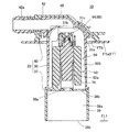
図1は本発明の第1実施例にかかる自動車の燃料タンクFTの上部に取り付けられる燃料遮断弁10を示す断面図である。図1において、燃料タンクFTは、その表面がポリエチレンを含む複合樹脂材料から形成されており、そのタンク上壁FTaに取付穴FTbが形成されている。このタンク上壁FTaには、燃料遮断弁10がその下部を取付穴FTbに突入した状態にて取り付けられている。燃料遮断弁10は、給油時に燃料タンク内の燃料が所定液位FL1まで上昇したときにキャニスタへの流出を規制するものである。
(1) Schematic Configuration of
(2) 燃料遮断弁10の各部の構成
燃料遮断弁10は、ケーシング20と、フロート機構50と、スプリング70とを主要な構成として備えている。ケーシング20は、ケーシング本体30と、底部材37と、蓋体40とを備え、ケーシング本体30と底部材37とにより囲まれたスペースが弁室30Sになっており、この弁室30Sにスプリング70に支持されたフロート機構50が収納されている。
(2) Configuration of Each Part of
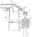
図2は燃料遮断弁10を分解した断面図である。ケーシング本体30は、天井壁部31と、側壁部32とにより囲まれたカップ形状であり、その下部を開口30aとしている。天井壁部31の中央部には、下方に向けて突設された通路形成突部31aが形成されており、この通路形成突部31aに接続通路31bが貫通形成されている。接続通路31bの弁室30S側は、シール部31cになっている。側壁部32には、燃料タンクFT内と弁室30Sとを接続する第1連通孔32aが形成されている。また、側壁部32の内壁には、フロート機構50をガイドするためのケース側ガイド部34が周方向に4カ所リブ形状で設けられている。ケース側ガイド部34は、ケーシング本体30の下部に形成された下ガイドリブ34aと、下ガイドリブ34aより軸心側へ形成された上ガイドリブ34bとを備えている。
FIG. 2 is an exploded cross-sectional view of the
底部材37は、ケーシング本体30の開口30aの一部を閉じるとともに、弁室30S内に燃料蒸気および液体燃料を導入するための部材である。底部材37は、底板38と、円筒部39とを一体に形成し、底板38の外周部でケーシング本体30の下端に溶着されている。底板38には、流通孔38a,38bが形成され、またスプリング70の下端を支持するためのスプリング支持部38cが形成されている。円筒部39は、導入通路39aを備えており、導入開口39bからの燃料蒸気および液体燃料を流通孔38aを通じて弁室30S内に導く。
The
蓋体40は、蓋本体41と、蓋本体41の中央から側方へ突出した管体部42と、蓋本体41の外周に形成されたフランジ43とを備え、これらを一体に形成している。管体部42には、蓋側通路42aが形成されており、この蓋側通路42aの一端は、接続通路31bを通じてケーシング本体30の弁室30Sに接続され、他端はキャニスタ(図示省略側)に接続される。蓋本体41の下部には、ケーシング本体30の外周部の上端を溶着する内部溶着端43aが形成されており、フランジ43の下端部には、燃料タンクFTのタンク上壁FTaに溶着される外側溶着部43bが形成されている。
The
フロート機構50は、再開弁特性を向上させた2段の弁構造であり、フロート52と、フロート52の上部に配置された上部弁体60とを備えている。フロート52は、第1フロート部53と、第2フロート部54とを備え、これらを一体に組み付けている。第1フロート部53は、第1フロート本体53aを備えている。第2フロート部54は、円筒形状であり、収納穴54aを有する第2フロート本体54bを備えている。この収納穴54aに第1フロート部53が嵌挿されることにより第1フロート部53と一体化している。上記第1フロート本体53aの外周部の段部は、スプリング支持部53bとなっており、スプリング70の上端を支持している。スプリング70は、第1フロート部53と第2フロート部54との間のスペースであるスプリング収納間隙52a(図1)の間に配置され、底部材37のスプリング支持部38cとの間にスプリング70を掛け渡している。
The
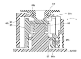
図3はフロート52、上部弁体60を構成する第1弁部61および第2弁部65を分解して示す斜視図、図4は上部弁体60の付近を分解して示す断面図である。第1フロート本体53aの上部には、弁支持部55が突設されている。弁支持部55は、上部弁体60を首振り可能に支持する部位であり、円柱状の突起である支持突部56を備えている。支持突部56の上面は、平面である支持面56aになっている。また、弁支持部55の外周部には、上部弁体60を抜止するとともにスプリング68の下端を支持するための環状突部57が形成されている。
3 is an exploded perspective view showing the
上部弁体60は、第1弁部61と、第2弁部65と、スプリング68とを備え、フロート52の弁支持部55に昇降可能かつ首振り可能に支持されている。
第1弁部61は、有底の円筒形状である第1弁本体62と、第1弁本体62に取り付けられるシート部材64とを備えている。第1弁本体62は、上面部62aと、上面部62aの外周部から突設された円筒形状の側壁62bとを備え、その内側スペースが支持孔62cになっている。上面部62aの中央部には、シート部材64を取り付けるための取付部62dが形成されている。また、第1弁本体62の上部の外周部には、支持孔62cを外部に接続するための通気孔62eが4箇所形成されている。図4に示す側壁62bの内周壁には、リブ状のガイド部62fが周方向に等間隔で4箇所上下方向に突設されており、第2弁部65を昇降可能にガイドする。また、側壁62bの内周壁には、第2弁部65と係合するための第1係合爪62gが弾性変形可能に形成されている。
The
The
シート部材64は、シール部31cに着離するシート部64aと、シート部64aの中央部を貫通して支持孔62cに接続される接続孔64bと、接続孔64bの下端部に形成されたシート部64cと、接続孔64bの外周部に形成された取付部64dとを備え、ゴム材料により一体成形されている。シート部材64は、取付部64dで第1弁本体62の取付部62dに圧入することで装着されており、シート部64aが第1弁本体62の上面部62aに対して間隙を有することで、シール部31cに着座するときに弾性変形してシール性を高めている。
The
第2弁部65は、円筒形状の第2弁本体66を備えている。第2弁本体66には、下方を開放した有底筒となった隔壁66aが形成されている。隔壁66aは、支持突部56に所定間隙を隔てて挿入されることによりフロート52に対して第2弁部65の大きな傾きを防止している。隔壁66aの上面中央部に、下方に向けてわずかに湾曲した凸形状の被支持部66bが形成されている。被支持部66bは、フロート52の支持面56a上に載置されることにより、第2弁部65が支持部55aを支点として首振り可能に支持されている。
また、第2弁本体66の上面には、第2シール部66cが形成されており、この第2シール部66cは、第1弁部61のシート部64cに着離することにより接続孔64bを開閉するように形成されている。第2弁本体66の下部には、第2抜止爪66dが4箇所形成されており、第1弁部61の第1係合爪62gに係合することにより、第1弁部61を第2弁部65に対して昇降可能に支持している。第2弁本体66の内壁には、係合爪66eが形成されており、フロート52の環状突部57に係合することにより、第2弁部65がフロート52に対して昇降可能に支持および抜止されている。
上部弁体60の重心は、被支持部66bより下方に設定されている。このための構成として、第1弁部61および第2弁本体66がそれぞれ円筒形状であり、支持面56aに支持される被支持部66bより下方に延設されている。
The
Further, a
The center of gravity of the
スプリング68は、フロート52の環状突部57と上部弁体60の底面に介在しており、フロート52がスプリング68を介して上部弁体60を支持している。スプリング68の付勢力は、上部弁体60が弁室30S内の燃料により浮力を受けていないときに被支持部66bが支持部55aで支持された状態にて上部弁体60を支持している(図1の状態)。
The
図5はフロート機構50の作用を説明する説明図である。図5に示すように車両の傾斜などにより矢印の方向へフロート52が傾いたとする。第2弁部65は、湾曲した凸形状である被支持部66bがフロート52の平面である支持部55aにより1点支持されているので、ヤジロベーのようにバランスをとり、第1弁部61のシート部材64は、水平姿勢を維持する。なお、上部弁体60が浮力を受けていないときには、上部弁体60の被支持部66bがフロート52の被支持部66bに載置された状態で支持され、スプリング68の付勢力で上部弁体60に対して浮上しない。また、フロート52の支持部55aが上部弁体60の被支持部66bを支持している状態から、フロート52が上部弁体60の第2弁部65に対して独立して下降することを許容する昇降距離Dmが確保されている。この昇降距離Dmは、フロート52がフロート52の環状突部57と係合爪66eとにより規定されている。
FIG. 5 is an explanatory diagram for explaining the operation of the
(3) 燃料遮断弁10の動作
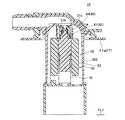
次に、燃料遮断弁10の動作について説明する。図1に示すように、給油により燃料タンクFT内に燃料が供給されると、燃料タンクFT内の燃料液位の上昇につれて燃料タンクFT内の上部に溜まっていた燃料蒸気は、円筒部39の導入開口39bから導入通路39aを経て、流通孔38a,38bから弁室30S内に流入する。さらに、燃料蒸気は、弁室30Sから接続通路31b、蓋側通路42aを通じて、キャニスタ側へ逃がされる。そして、燃料タンクFT内の燃料液位が所定液位FL1に達すると、燃料は導入開口39bを塞ぐことにより、燃料タンクFT内のタンク内圧が上昇する。この状態では、タンク内圧と弁室30S内の圧力との差圧が大きくなり、液体燃料が導入通路39a、流通孔38a,38bを通じて、弁室30Sに流れ込み、燃料液位が弁室30S内を上昇する。そして、図6に示すように、弁室30S内の燃料液位が高さh0に達すると、フロート52の浮力およびスプリング70の荷重による上方への力と、フロート機構50の自重による下方への力との釣り合いによって、前者が後者を上回りフロート機構50が一体になって上昇して、上部弁体60のシート部材64がシール部31cに着座して接続通路31bを閉じる。このとき、インレットパイプ内に燃料が溜まり、給油ガンに燃料が触れると、オートストップを働かせる。これにより、燃料タンクFTへの給油の際等に、燃料タンクFTから燃料蒸気を逃がすとともに燃料が燃料タンクFT外へ流出するのを防止することができる。
(3) Operation of the
一方、燃料タンクFT内の燃料が消費されて、燃料液位が低下すると、フロート52は、その浮力を減少して下降する。フロート52の下降により、図7に示すように、フロート52の環状突部57と第2弁部65の係合爪66eとの係合を介して、フロート52は、第2弁部65を引き下げる。これにより、第2シール部66cは、シート部64cから離れて、接続孔64bを開く。接続孔64bの連通により第1弁部61の下方の圧力は、接続通路31bの付近と同じ圧力になる。そして、第2抜止爪66dと第1係合爪62gとの係合を介して、第2弁部65は第1弁部61も引き下げる。そして、第1弁部61が下降することで、シート部材64がシール部31cから離れて、接続通路31bが開かれる。このように、第2弁部65および第1弁部61による2段の弁構造により、再開弁特性の向上を促進するように機能する。すなわち、シート部64cが第2シール部66cから離れて通路面積を小さくした接続孔64bが最初に連通するから、第1弁部61の下部の圧力が低減されて第1弁部61の閉弁方向の力が小さくなり、よって再開弁特性に優れている。
On the other hand, when the fuel in the fuel tank FT is consumed and the fuel level is lowered, the
また、車両が坂道を走行して傾斜したときに弁室30S内に燃料が満たされて上部弁体60が液没することがある。このような状況にて、車両の振動が燃料遮断弁10に加わった場合にも、図8に示すように上部弁体60のシート部64cと第2シール部66cとの間のシール性を維持する。すなわち、フロート52の環状突部57と係合爪66eとの間には、フロート52が上部弁体60の第2弁部65に対して独立して下降することを許容する昇降距離Dm(図5参照)が確保されている。このため、フロート52は、昇降距離Dmの範囲内で下降しても、第2弁部65を下降させる力を加えず、つまりシート部64cと第2シール部66cとを引き離す方向への力を加えない。しかも、上部弁体60の浮力が増大することにより、該浮力とスプリング68の上方への付勢力とを合計した上方への力と上部弁体60の重力による下方への力との差が増大するから、上部弁体60を接続通路31bのシール部31cに押す力が増す。よって、車両の振動等に起因した微振動が燃料遮断弁10に及んでも、上部弁体60が接続通路31bのシール部31cから離れにくく、シール性の低下を招くことがない。
Further, when the vehicle travels on a slope and inclines, the
(4) 実施例の作用・効果
上記実施例の構成により、以下の作用・効果を奏する。
(4)−1 給油により燃料タンク内の燃料液位が導入開口39bを塞ぐ所定液位FL1を越えると、燃料タンクFTのタンク内圧が上昇するので、オートストップを働かせることができる。
(4) Actions and effects of the embodiment The following actions and effects are exhibited by the configuration of the above embodiment.
(4) -1 When the fuel level in the fuel tank exceeds the predetermined liquid level FL1 that closes the introduction opening 39b by refueling, the tank internal pressure of the fuel tank FT rises, so that an automatic stop can be activated.
(4)−2 上部弁体60は、フロート52の上部に設けた支持部55aの支持面56aにより、被支持部66bで1カ所の支点で支持され、しかも、上部弁体60の重心は支点より低い位置にあるから、支点を中心にバランスをとり、上部弁体60の姿勢が安定する。また、支持面56aは、平面であり、被支持部66bが凸部であるから、凸部が多少摩耗しても、水平姿勢を維持する機能を損なうことがない。よって、車両の傾斜によりフロート52が傾いたりしても、上部弁体60は、長期間にわたって安定した水平姿勢を維持し、接続通路31bのシール部31cに対して確実に着離して、高いシール性を得ることができる。このとき、上部弁体60とフロート52との間に介在するスプリング68は、上部弁体60に浮力が加わっていない場合、つまり上部弁体が液没していない場合には、フロート52から離れないから、上述したバランス作用を損なうことがない。
(4) -2 The
(4)−3 上部弁体60は、ヤジロベーの原理により姿勢を安定する動作を自らとるから、シール部31cに押しつける力も小さくてよく、閉弁に必要なフロート52の上昇力も小さく、車両の傾斜時になどに生じる微少な燃料液位の上昇にも対応することができる。しかも、フロート52の軸心と異なる位置に上部弁体60の凸形状である被支持部66bが支持面56aで支持されても、被支持部66bを支点にしてバランスをとるから上部弁体60の姿勢が安定する。
(4) -3 Since the
(4)−4 燃料タンクFTの上部スペース内に溜まっている燃料蒸気は、給油時における燃料液位の上昇に伴って、弁室30S内で上昇気流となり、第1弁部61の支持孔62c内に入り込むが、支持孔62cとガイド筒体66fとの間隙を通り、通気孔62eから逃がされる。したがって、支持孔62cを流れる上昇気流は、支持孔62cの上部で留まることがなく、通気孔62eを通じて逃がされる。このため、支持孔62c内の圧力が部分的に高くなって、第2弁部65を第1弁部61に対して引き離すような力が加わることがない。しかも、第1弁部61のガイド部62fは、支持孔62cの内壁に形成されており、第2弁部65を傾かせることなく、第1弁部61に対してガイドする。したがって、第2弁部65は、昇降する際に傾くことがなく、第2シール部66cがシート部64cに高いシール性で着座し、その間のシール性の低下に伴う不具合、つまり燃料がその間隙から接続孔64b、接続通路31bを通じて外部へ流出するような不具合を生じない。
(4) -4 The fuel vapor accumulated in the upper space of the fuel tank FT becomes an ascending current in the
(4)−5 上部弁体60が液没した場合には、上部弁体60の浮力が増大することにより、該浮力とスプリング68の上方への付勢力とを合わせた上方への力と上部弁体60の重力による下方への力との差が増大するから、上部弁体60を接続通路31bのシール部31cに押す力が増す。したがって、車両の振動等に起因した微振動が燃料遮断弁10に及んでも、上部弁体60が接続通路のシール部31cから離れにくく、シール性の低下を招くことがない。
(4) -5 When the
(4)−6 第2弁部65の隔壁66aは、弁支持部55に所定間隙を隔てて挿入されているから、首振り状態で支持されている上部弁体60に傾きを生じるような力が加わっても、フロート52に対して第2弁部65の大きな傾きを防止し、シール性の低下を招かない。また、隔壁66aは、スプリング68と支持部55aとの間に介在して、スプリング68と支持部55aとが干渉するのを防止し、よって上部弁体60のスムーズな昇降を可能とする。
(4) -6 Since the
(5) 第2実施例
図9は第2実施例にかかる上部弁体の付近を示す断面図である。本実施例は、支持部および被支持部の構成および上部弁体を支持するスプリングの支持構造に特徴を有する。フロート52Bの上部に突設された弁支持部55Bの上部には、支持部55Baが凸形状に形成されている。また、上部弁体60Bは、第1弁部61Bと、第2弁部65Bとを備え、第2弁部65Bの下部に凹形状の被支持部66Bbが形成され、弁支持部55Bに首振り可能に支持されている。スプリング68Bは、第2弁部65Bの下端とフロート52Bの上面との間に掛け渡されている。スプリング68Bは、第2弁部65Bに閉弁方向の力を加えており、車両の振動等に起因した微振動が燃料遮断弁に及んでも、第2弁部65Bが第2シール部66Bcから離れにくく、第2弁部65Bの開弁動作に至らないように作用する。
(5) 2nd Example FIG. 9: is sectional drawing which shows the vicinity of the upper valve body concerning 2nd Example. This embodiment is characterized by the structure of the support part and the supported part and the support structure of the spring that supports the upper valve body. A support portion 55Ba is formed in a convex shape on the upper portion of the
(6) 第3実施例
図10は第3実施例にかかる上部弁体の付近を示す断面図である。本実施例は、フロートと上部弁体とを連結する構成に特徴を有する。フロート52Cの上部には、上部弁体60Cと係合する係合爪52Cbが突設されている。一方、上部弁体60Cは、第1弁部61Cと、第2弁部65Cとを備えている。第1弁部61Cの筒体部63Caには、係合穴63Cbが形成されている。第2弁部65Cの円筒部67Caには、抜止爪67Cbおよび係合穴67Ccが形成されている。スプリング68Cは、フロート52Cの上面と第2弁部65Cの底面との間に掛け渡され、第2弁部65Cを上方に付勢している。
本実施例の構成において、フロート52Cが下降すると、係合爪52Cbが係合穴67Ccに係合し、第2弁部65Cを引き下げる。フロート52Cが第2弁部65Cと一体に下降すると、抜止爪67Cbが係合穴63Cbに係合して第1弁部61Cを引き下げる。このような係合構造により、フロート52Cが下降する力が、第1弁部61Cから第2弁部65Cに伝えられる。
(6) Third Example FIG. 10 is a cross-sectional view showing the vicinity of an upper valve body according to a third example. The present embodiment is characterized by a configuration in which the float and the upper valve body are connected. An engaging claw 52Cb that engages with the
In the configuration of the present embodiment, when the
(7) 第4実施例
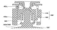
図11は第4実施例にかかる上部弁体の付近を示す断面図である。本実施例は、スプリングの配置および構成に特徴を有する。上部弁体60Dは、第1弁部61Dと、第2弁部65Dとを備え、第2弁部65Dの下部とフロート52Dの弁支持部55Dとの間に掛け渡されたスプリング68Dにより支持されている。スプリング68Dは、その下端が弁支持部55Dの下部に形成された環状突部55Dbに支持され、その上端が第2弁部65Dに形成された収納溝65Daの底に支持され、車両の振動等に起因した微振動が燃料遮断弁に及んでも、第2弁部65Dが第2シール部66Dcから離れにくく、第2弁部65Dの開弁動作に至らないように作用する。しかも、スプリング68Dは、収納溝65Daに収納されて伸縮するから、弁支持部55Dに干渉することがない。
(7) Fourth Example FIG. 11 is a cross-sectional view showing the vicinity of an upper valve body according to a fourth example. This embodiment is characterized by the arrangement and configuration of the spring. The
(8) 第5実施例
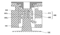
図12は第5実施例にかかる上部弁体の付近を示す断面図である。本実施例は、上部弁体60Eを支持するためのスプリングの配置および構成に特徴を有する。上部弁体60Eは、第1弁部61Eと、第2弁部65Eとを備え、第2弁部65Eの下部と弁支持部55Eとの間に掛け渡されたスプリング68Eにより支持されている。すなわち、フロート52Eの上部から突設された弁支持部55Eの上端から、軸心の下方に向けて、スプリング68Eを収納する収納凹所55Ecが形成され、一方、第2弁部65Eの下部からスプリング68E内に挿入されスプリング68Eの位置ズレを防止する突出部65Ecが形成されている。
(8) Fifth Embodiment FIG. 12 is a cross-sectional view showing the vicinity of the upper valve body according to the fifth embodiment. This embodiment is characterized by the arrangement and configuration of springs for supporting the
(9) 第6実施例
図13は第6実施例にかかる上部弁体の付近を示す断面図である。本実施例は、上部弁体の一部を支持するためのスプリングおよび支持部の構成に特徴を有する。上部弁体60Fは、第1弁部61Fと、第2弁部65Fとを備え、フロート52Fと別体に形成された弁支持部55Fと、スプリング68Fにより支持されている。すなわち、弁支持部55Fは、その上部に支持部55Faを備え、その下部から上方に向けてスプリング68Fを収納する収納室55Feを備えている。スプリング68Fは、フロート52Fの上面で支持されるとともに、収納室55Fe内に収納され支持部55Faの下部に当たって支持部55Faを上方に付勢することにより、支持部55Faおよび被支持部66Fbを介して第2弁部65Fを支持している。弁支持部55Fは、その下部の拡張部55Ffがフロート52Fの上部から突出した抜止部55Fdの上部の爪55Fgに係合することにより抜止めされている。
なお、スプリング68Fの付勢力は、図13に示すように、フロート52Fの上面から弁支持部55Fが離れている強さに設定するほか、弁支持部55Fがフロート52Fの上面に載置されている状態となる強さに設定してもよく、あるいは、この範囲となる強さに設定してもよく、いずれの場合であってもヤジロベー構造により支持する作用を果たすことができる。
(9) Sixth Embodiment FIG. 13 is a cross-sectional view showing the vicinity of an upper valve body according to a sixth embodiment. This embodiment is characterized by the structure of a spring and a support portion for supporting a part of the upper valve body. The
As shown in FIG. 13, the urging force of the
(10) 第7実施例
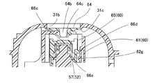
図14は第7実施例にかかる燃料遮断弁を示す断面図である。本実施例にかかる燃料遮断弁は、シール部31Gcや上部弁体60Gの構成に特徴を有する。すなわち、ケーシング20Gの接続通路31Gbに臨んでゴム製のシール部材SPが装着され、そのシール部材の下部にシール部31Gcが設けられている。また、上部弁体60Gは、弁本体62Gに設けられ接続通路31Gbを開閉するシート部64Gaと、湾曲した凸形状の被支持部66Gbを有する弁本体62Gと、を備え、単一の樹脂部材から形成されている。また、フロート52Gの支持面56Gaは、被支持部66Gbより曲率の大きい凹面に形成されている。この構成において、上部弁体60Gの被支持部66Gbがフロート52Gの支持面56Gaに支持されたときに、該支持されている上端部を支点としてバランスをとるよう作用する。しかも、支持面56Gaが湾曲した凹所であるから、凸部である被支持部66Gbが支持面56Gaの中心に向けて滑るから、調芯作用を備えている。
また、フロート52Gの環状突部57Gと上部弁体60Gの底面には、スプリング68Gが介在し、フロート52Gが上部弁体60Gを支持している。このスプリング68Gにより、上部弁体60Gが液没した状態でも上部弁体60Gの閉弁方向の力を加えており、車両の振動等に起因した微振動が燃料遮断弁に及んでも、上部弁体60Gのシート部64Gaがシール部31Gcから離れにくく、上部弁体60Gの開弁動作に至らないように作用する。
(10) Seventh Embodiment FIG. 14 is a cross-sectional view showing a fuel cutoff valve according to a seventh embodiment. The fuel cutoff valve according to the present embodiment is characterized by the configuration of the seal portion 31Gc and the
A
(11) 第8実施例
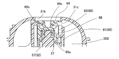
図15は第8実施例にかかる燃料遮断弁を示す断面図である。本実施例にかかる燃料遮断弁は、第7実施例の変形例にかかり、上部弁体60Hの支持構造に特徴を有する。すなわち、フロート52Hの支持部55Haが凸形状に形成され、上部弁体60Hの被支持部66Hbが凹形状に形成され、支持部55Haでバランスするように支持されている。
(11) Eighth Embodiment FIG. 15 is a cross-sectional view showing a fuel cutoff valve according to an eighth embodiment. The fuel cutoff valve according to the present embodiment is a modification of the seventh embodiment and has a feature in the support structure of the
なお、この発明は上記実施例に限られるものではなく、その要旨を逸脱しない範囲において種々の態様において実施することが可能であり、例えば次のような変形も可能である。
上記実施例では、燃料遮断弁をタンクの上壁の上面に装着した構成について説明したが、これに限らず、燃料遮断弁を燃料タンクの上壁の内面に装着する、いわゆるインタンク式であってもよい。
The present invention is not limited to the above-described embodiments, and can be implemented in various modes without departing from the gist thereof. For example, the following modifications are possible.
In the above embodiment, the configuration in which the fuel cutoff valve is mounted on the upper surface of the upper wall of the tank has been described. However, the present invention is not limited to this, and a so-called in-tank type in which the fuel cutoff valve is mounted on the inner surface of the upper wall of the fuel tank. May be.
10...燃料遮断弁
20...ケーシング
20G...ケーシング
30...ケーシング本体
30S...弁室
30a...開口
31...天井壁部
31a...通路形成突部
31b...接続通路
31Gb...接続通路
31c...シール部
31Gc...シール部
32...側壁部
32a...第1連通孔
34...ケース側ガイド部
34a...下ガイドリブ
34b...上ガイドリブ
37...底部材
38...底板
38a,38b...流通孔
38c...スプリング支持部
39...円筒部
39a...導入通路
39b...導入開口
40...蓋体
41...蓋本体
42...管体部
42a...蓋側通路
43...フランジ
43a...内部溶着端
43b...外側溶着部
50...フロート機構
52...フロート
52B...フロート
52C...フロート
52D...フロート
52E...フロート
52F...フロート
52G...フロート
52H...フロート
52a...スプリング収納間隙
52Cb...係合爪
53...第1フロート部
53a...第1フロート本体
53b...スプリング支持部
54...第2フロート部
54a...収納穴
54b...第2フロート本体
55...弁支持部
55a...支持部
55B...弁支持部
55Ba...支持部
55D...弁支持部
55Db...環状突部
55E...弁支持部
55Ec...収納凹所
55F...弁支持部
55Fa...支持部
55Fd...抜止部
55Fe...収納室
55Ff...拡張部
55Fg...爪
55Ha...支持部
56...支持突部
56a...支持面
56Ga...支持面
57...環状突部
57G...環状突部
60...上部弁体
60B...上部弁体
60C...上部弁体
60D...上部弁体
60E...上部弁体
60F...上部弁体
60G...上部弁体
60H...上部弁体
61...第1弁部
61B...第1弁部
61C...第1弁部
61D...第1弁部
61E...第1弁部
61F...第1弁部
62...第1弁本体
62a...上面部
62b...側壁
62c...支持孔
62d...取付部
62e...通気孔
62f...ガイド部
62G...弁本体
62g...第1係合爪
63Ca...筒体部
63Cb...係合穴
64...シート部材
64a...シート部
64b...接続孔
64c...シート部
64d...取付部
64Ga...シート部
65...第2弁部
65B...第2弁部
65C...第2弁部
65D...第2弁部
65Da...収納溝
65E...第2弁部
65Ec...突出部
65F...第2弁部
66...第2弁本体
66a...隔壁
66b...被支持部
66Bb...被支持部
66c...第2シール部
66Bc...第2シール部
66d...第2抜止爪
66Dc...第2シール部
66e...係合爪
66f...ガイド筒体
66Fb...被支持部
66Gb...被支持部
66Hb...被支持部
67Ca...円筒部
67Cb...抜止爪
67Cc...係合穴
68...スプリング
68B...スプリング
68C...スプリング
68D...スプリング
68E...スプリング
68F...スプリング
68G...スプリング
70...スプリング
FT...燃料タンク
FTa...タンク上壁
FTb...取付穴
SP...シール部材
DESCRIPTION OF
Claims (10)
上記燃料タンク(FT)内と上記接続通路(31b)とを連通する弁室(30S)を形成するケーシング(20)と、
上記弁室(30S)に収納され該弁室(30S)内の燃料液位により浮力を増減して昇降するフロート(52)と、
上記フロート(52)の上部に載置され該フロート(52)が昇降することで上記接続通路(31b)を開閉する上部弁体(60)と、
上記フロート(52)の上部と上部弁体(60)との間に介在し、上記上部弁体(60)を上方に向けて付勢するスプリング(68)と、
を備え、
上記フロート(52)は、該フロート(52)の上部に設けられ上記上部弁体(60)を支持する支持部(55a)を有し、
上記上部弁体(60)は、上記支持部(55a)に支持される被支持部(66b)を備え、該被支持部(66b)が上記支持部(55a)に支持されたときに、該支持されている部位を支点としてバランスをとるように該支点より下方に重心が設定され、
上記スプリング(68)の付勢力は、上記上部弁体(60)が上記弁室(30S)内の燃料により浮力を受けていないときに上記被支持部(66b)が上記支持部(55a)で支持されるように設定されていること、
を特徴とする燃料遮断弁。 A fuel cutoff valve that is mounted on the upper part of the fuel tank (FT) and that opens and closes a connection passage (31b) that connects the inside of the fuel tank (FT) and the outside, thereby disconnecting the fuel tank (FT) from the outside. ,
A casing (20) forming a valve chamber (30S) communicating the fuel tank (FT) and the connection passage (31b);
A float (52) which is housed in the valve chamber (30S) and moves up and down with increasing or decreasing buoyancy depending on the fuel level in the valve chamber (30S);
An upper valve body (60) placed on top of the float (52) and opening and closing the connection passage (31b) by raising and lowering the float (52);
A spring (68) interposed between the upper part of the float (52) and the upper valve body (60) and biasing the upper valve body (60) upward;
With
The float (52) has a support portion (55a) that is provided on the top of the float (52) and supports the upper valve body (60),
The upper valve body (60) includes a supported portion (66b) supported by the support portion (55a), and when the supported portion (66b) is supported by the support portion (55a), The center of gravity is set below the fulcrum so as to balance the supported part as a fulcrum,
The urging force of the spring (68) is such that when the upper valve body (60) is not receiving buoyancy from the fuel in the valve chamber (30S), the supported portion (66b) is the support portion (55a). Be set to be supported,
A fuel shut-off valve characterized by
上記フロート(52)は、該フロート(52)の上部から突設されその上面に上記支持部(55a)を有する弁支持部(55)を備え、
上記上部弁体(60)は、該上部弁体(60)の下部から上記弁支持部(55)を囲むように突設された隔壁(66a)を備え、該隔壁(66a)は上記スプリング(68)と上記支持部(55a)との間に介在するように形成した燃料遮断弁。 The fuel cutoff valve according to claim 1,
The float (52) includes a valve support (55) protruding from the top of the float (52) and having the support (55a) on the upper surface thereof.
The upper valve body (60) includes a partition wall (66a) projecting from the lower part of the upper valve body (60) so as to surround the valve support portion (55), and the partition wall (66a) includes the spring ( 68) and a fuel cutoff valve formed so as to be interposed between the support portion (55a).
上記上部弁体(60)は、該上部弁体(60)の下部であって上記隔壁(66a)の外周側に形成された円筒形状の側壁(62b)を備えている燃料遮断弁。 The fuel cutoff valve according to claim 2,
The upper valve body (60) is a fuel cutoff valve provided with a cylindrical side wall (62b) formed on the outer peripheral side of the partition wall (66a) below the upper valve body (60).
上記弁支持部(55)は、該弁支持部(55)の外周部から突設され上記スプリング(68)の下端を支持する環状突部(57)を備えた燃料遮断弁。 The fuel cutoff valve according to claim 2 or claim 3,
The said valve support part (55) is a fuel cutoff valve provided with the annular protrusion (57) which protrudes from the outer peripheral part of this valve support part (55), and supports the lower end of the said spring (68).
上記フロート(52)は、上記フロート(52)の上部から突設されその上面に上記支持部(55a)を有する弁支持部(55)を備え、
上記上部弁体(60)は、
支持孔(62c)を有する第1弁本体(62)と、該第1弁本体(62)に設けられ上記接続通路(31b)を開閉するシート部(64a)と、該シート部(64a)に貫通形成されることで上記支持孔(62c)に接続されかつ上記接続通路(31b)より通路面積が小さい接続孔(64b)とを有する第1弁部(61)と、
上記支持孔(62c)に昇降可能に収納され上記被支持部(66b)を有する第2弁本体(66)と、該第2弁本体(66)の上部に設けられ上記接続孔(64b)を開閉する第2シール部(66c)とを有する第2弁部(65)と、
を備え、
上記スプリング(68)は、上記第2弁本体(66)と上記フロート(52)の上部との間に介在している燃料遮断弁。 The fuel cutoff valve according to claim 1,
The float (52) includes a valve support (55) protruding from the top of the float (52) and having the support (55a) on the upper surface thereof.
The upper valve body (60)
A first valve body (62) having a support hole (62c), a seat part (64a) provided in the first valve body (62) for opening and closing the connection passage (31b), and the seat part (64a) A first valve portion (61) having a connection hole (64b) connected to the support hole (62c) by being formed through and having a passage area smaller than the connection passage (31b);
A second valve body (66) that is housed in the support hole (62c) so as to be movable up and down and has the supported portion (66b), and the connection hole (64b) provided on the upper portion of the second valve body (66). A second valve portion (65) having a second seal portion (66c) for opening and closing;
With
The spring (68) is a fuel cutoff valve interposed between the second valve body (66) and the upper part of the float (52).
上記第1弁本体(62)は、円筒形状の側壁(62b)を備え、上記第2弁本体(66)は、上記第1弁本体(62)内に収納される円筒形状のガイド筒体(66f)を備えている燃料遮断弁。 The fuel cutoff valve according to claim 5,
The first valve main body (62) includes a cylindrical side wall (62b), and the second valve main body (66) is a cylindrical guide cylinder (not shown) accommodated in the first valve main body (62). 66f).
上記第1弁本体(62)は、第1係合爪(62g)を備え、上記第2弁本体(66)は、上記第1係合爪(62g)に係合する第2抜止爪(66d)を備え、上記第1係合爪(62g)と第2抜止爪(66d)とが係合する位置は、上記支持部(55a)より下方に設定されている燃料遮断弁。 The fuel cutoff valve according to claim 6,
The first valve body (62) includes a first engagement claw (62g), and the second valve body (66) engages with the first engagement claw (62g). ), And the position at which the first engaging claw (62g) and the second retaining claw (66d) engage is set to be lower than the support portion (55a).
上記第2弁部(65D)は、上記スプリング(68D)を収納する収納溝(65Da)を備え、該収納溝(65Da)は、上記スプリング(68D)が上記弁支持部(55D)に接触するのを防ぐように構成されている燃料遮断弁。 The fuel cutoff valve according to claim 5 ,
The second valve portion (65D) includes a storage groove (65Da) that stores the spring (68D), and the spring (68D) contacts the valve support portion (55D). A fuel shut-off valve configured to prevent this.
上記弁支持部(55E)は、上記スプリング(68E)を収納する収納凹所(55Ec)を備え、
上記第1弁部(61E)は、上記スプリング(68E)内に挿入される突出部(65Ec)を備えている燃料遮断弁。 The fuel cutoff valve according to claim 5 ,
The valve support (55E) includes a storage recess (55Ec) for storing the spring (68E),
The first valve portion (61E) is a fuel cutoff valve provided with a protrusion (65Ec) inserted into the spring ( 68E ).
上記燃料タンク内と上記接続通路とを連通する弁室を形成するケーシングと、
上記弁室に収納され該弁室内の燃料液位により浮力を増減して昇降するフロート(52F)と、
上記フロート(52F)の上方に配置され該フロート(52F)が昇降することで上記接続通路を開閉する上部弁体(60F)と、
上記フロート(52F)と上記上部弁体(60F)との間に配置されるとともに該フロート(52F)と別体に形成され上記上部弁体(60F)を支持する支持部(55Fa)と、
上記フロート(52F)の上部で支持され、上記支持部55Faを閉弁方向に付勢するスプリング(68F)と、
を備え、
上記上部弁体(60F)は、上記支持部(55Fa)に支持される被支持部(66Fb)を備え、該被支持部(66Fb)が上記支持部(55Fa)に支持されたときに、該支持されている部位を支点としてバランスをとるように該支点より下方に重心が設定されていること、を特徴とする燃料遮断弁。 In a fuel cutoff valve that is mounted on the upper part of the fuel tank and that opens and closes a connection passage that connects the inside and outside of the fuel tank so as to cut off communication between the fuel tank and the outside.
A casing forming a valve chamber communicating the inside of the fuel tank and the connection passage;
A float (52F) that is housed in the valve chamber and moves up and down with increasing or decreasing buoyancy depending on the fuel level in the valve chamber;
An upper valve body (60F) which is disposed above the float (52F) and opens and closes the connection passage when the float (52F) moves up and down;
A support portion (55Fa) disposed between the float (52F) and the upper valve body (60F) and formed separately from the float (52F) and supporting the upper valve body (60F);
A spring (68F) supported at the top of the float (52F) and biasing the support portion 55Fa in the valve closing direction;
With
The upper valve body (60F) includes a supported portion (66Fb) supported by the support portion (55Fa), and when the supported portion (66Fb) is supported by the support portion (55Fa), A fuel cutoff valve, characterized in that a center of gravity is set below the fulcrum so as to balance the supported part.
Priority Applications (1)
| Application Number | Priority Date | Filing Date | Title |
|---|---|---|---|
| JP2006022330A JP4635886B2 (en) | 2006-01-31 | 2006-01-31 | Fuel shut-off valve |
Applications Claiming Priority (1)
| Application Number | Priority Date | Filing Date | Title |
|---|---|---|---|
| JP2006022330A JP4635886B2 (en) | 2006-01-31 | 2006-01-31 | Fuel shut-off valve |
Publications (2)
| Publication Number | Publication Date |
|---|---|
| JP2007203789A JP2007203789A (en) | 2007-08-16 |
| JP4635886B2 true JP4635886B2 (en) | 2011-02-23 |
Family
ID=38483640
Family Applications (1)
| Application Number | Title | Priority Date | Filing Date |
|---|---|---|---|
| JP2006022330A Expired - Fee Related JP4635886B2 (en) | 2006-01-31 | 2006-01-31 | Fuel shut-off valve |
Country Status (1)
| Country | Link |
|---|---|
| JP (1) | JP4635886B2 (en) |
Families Citing this family (1)
| Publication number | Priority date | Publication date | Assignee | Title |
|---|---|---|---|---|
| JP4869201B2 (en) * | 2007-10-02 | 2012-02-08 | 株式会社パイオラックス | Float valve device |
Citations (6)
| Publication number | Priority date | Publication date | Assignee | Title |
|---|---|---|---|---|
| JPS63150175U (en) * | 1987-03-25 | 1988-10-03 | ||
| JPH04365624A (en) * | 1990-11-30 | 1992-12-17 | Nissan Motor Co Ltd | Fuel cut-off device for fuel tank |
| JPH07279789A (en) * | 1994-04-07 | 1995-10-27 | Aisin Seiki Co Ltd | Liquid level control valve |
| JPH07280117A (en) * | 1994-04-05 | 1995-10-27 | Toyoda Gosei Co Ltd | Float valve for fuel tank |
| JP2002235623A (en) * | 2001-01-05 | 2002-08-23 | Walbro Corp | Vent valve and fuel pump module |
| JP2005016507A (en) * | 2003-05-30 | 2005-01-20 | Toyoda Gosei Co Ltd | Fuel cutoff valve |
-
2006
- 2006-01-31 JP JP2006022330A patent/JP4635886B2/en not_active Expired - Fee Related
Patent Citations (6)
| Publication number | Priority date | Publication date | Assignee | Title |
|---|---|---|---|---|
| JPS63150175U (en) * | 1987-03-25 | 1988-10-03 | ||
| JPH04365624A (en) * | 1990-11-30 | 1992-12-17 | Nissan Motor Co Ltd | Fuel cut-off device for fuel tank |
| JPH07280117A (en) * | 1994-04-05 | 1995-10-27 | Toyoda Gosei Co Ltd | Float valve for fuel tank |
| JPH07279789A (en) * | 1994-04-07 | 1995-10-27 | Aisin Seiki Co Ltd | Liquid level control valve |
| JP2002235623A (en) * | 2001-01-05 | 2002-08-23 | Walbro Corp | Vent valve and fuel pump module |
| JP2005016507A (en) * | 2003-05-30 | 2005-01-20 | Toyoda Gosei Co Ltd | Fuel cutoff valve |
Also Published As
| Publication number | Publication date |
|---|---|
| JP2007203789A (en) | 2007-08-16 |
Similar Documents
| Publication | Publication Date | Title |
|---|---|---|
| JP4415888B2 (en) | Fuel shut-off valve | |
| JP4730218B2 (en) | Fuel shut-off valve | |
| US20090236350A1 (en) | Ventilating device for fuel tank | |
| JP2014088126A (en) | Fuel shut-off valve | |
| US7963296B2 (en) | Fuel cutoff valve | |
| JP2006009645A (en) | Fuel cutoff valve | |
| JP2007177784A (en) | Flow channel structure for tank | |
| JP4694533B2 (en) | Fuel shut-off valve | |
| JP4635886B2 (en) | Fuel shut-off valve | |
| JP2008075596A (en) | Fuel cutoff valve | |
| JP4807341B2 (en) | Fuel shut-off valve | |
| JP2010173397A (en) | Fuel shutoff valve | |
| JP4193782B2 (en) | Fuel shut-off valve | |
| JP4518022B2 (en) | Fuel shut-off valve | |
| JP2008184093A (en) | Fuel cutoff valve | |
| JP2007261384A (en) | Fuel shutoff valve | |
| JP4487915B2 (en) | Fuel shut-off valve | |
| JP4301086B2 (en) | Fuel shut-off valve | |
| JP4586784B2 (en) | Fuel shut-off valve | |
| JP2008080945A (en) | Fuel shutting-off valve | |
| JP4407534B2 (en) | Fuel shut-off valve | |
| JP4432890B2 (en) | Tank channel structure | |
| JP2009078647A (en) | Fuel shutoff valve | |
| JP4635867B2 (en) | Fuel shut-off valve | |
| JP2008031992A (en) | Fuel shut-off valve |
Legal Events
| Date | Code | Title | Description |
|---|---|---|---|
| A621 | Written request for application examination |
Free format text: JAPANESE INTERMEDIATE CODE: A621 Effective date: 20080226 |
|
| A977 | Report on retrieval |
Free format text: JAPANESE INTERMEDIATE CODE: A971007 Effective date: 20100430 |
|
| A131 | Notification of reasons for refusal |
Free format text: JAPANESE INTERMEDIATE CODE: A131 Effective date: 20100608 |
|
| A521 | Written amendment |
Free format text: JAPANESE INTERMEDIATE CODE: A523 Effective date: 20100804 |
|
| TRDD | Decision of grant or rejection written | ||
| A01 | Written decision to grant a patent or to grant a registration (utility model) |
Free format text: JAPANESE INTERMEDIATE CODE: A01 Effective date: 20101026 |
|
| A01 | Written decision to grant a patent or to grant a registration (utility model) |
Free format text: JAPANESE INTERMEDIATE CODE: A01 |
|
| A61 | First payment of annual fees (during grant procedure) |
Free format text: JAPANESE INTERMEDIATE CODE: A61 Effective date: 20101108 |
|
| FPAY | Renewal fee payment (event date is renewal date of database) |
Free format text: PAYMENT UNTIL: 20131203 Year of fee payment: 3 |
|
| R150 | Certificate of patent or registration of utility model |
Free format text: JAPANESE INTERMEDIATE CODE: R150 |
|
| LAPS | Cancellation because of no payment of annual fees |
