JP4635786B2 - Optical fiber connection terminal - Google Patents
Optical fiber connection terminal Download PDFInfo
- Publication number
- JP4635786B2 JP4635786B2 JP2005253776A JP2005253776A JP4635786B2 JP 4635786 B2 JP4635786 B2 JP 4635786B2 JP 2005253776 A JP2005253776 A JP 2005253776A JP 2005253776 A JP2005253776 A JP 2005253776A JP 4635786 B2 JP4635786 B2 JP 4635786B2
- Authority
- JP
- Japan
- Prior art keywords
- optical fiber
- connection
- optical
- connection terminal
- face
- Prior art date
- Legal status (The legal status is an assumption and is not a legal conclusion. Google has not performed a legal analysis and makes no representation as to the accuracy of the status listed.)
- Expired - Fee Related
Links
Images


Landscapes
- Optical Couplings Of Light Guides (AREA)
- Optical Fibers, Optical Fiber Cores, And Optical Fiber Bundles (AREA)
- Mechanical Coupling Of Light Guides (AREA)
Description
本発明は、光ファイバの接続端末に関するものである。 The present invention relates to a connection end at the end of the optical fiber.
従来より、光ファイバの接続において、その端面を略凸状に研磨等で形成したのち、両光ファイバ端面間に押圧力を作用させながら接続する「PC(フィジカル・コンタクト)接続」が一般的である。光ファイバのコア部端面が凸状になっているが、押圧力によって弾性変形させ、相手側のコア部と隙間を介さずに物理的に接触することができ、光信号の接続端面における反射減衰を抑制できる効果がある(例えば特許文献1)。
接続端面を傾斜させる方法も一般的である。基本的にはそれであっても上記のようにPC接続させるが、仮に何らかの原因でPC接続が行えない事態となっても、端面が傾斜しているがゆえにガラス端と隙間の境界面で反射する光信号が後戻りせずにクラッド側へ逃げることになり、伝送特性に及ぼす悪影響を軽減させることが出来る(例えば特許文献2参照)。
A method of inclining the connection end face is also common. Basically, even though it is connected to the PC as described above, even if the PC connection cannot be made for some reason, it is reflected at the boundary surface between the glass edge and the gap because the end surface is inclined. The optical signal escapes to the clad side without returning, and the adverse effect on the transmission characteristics can be reduced (for example, see Patent Document 2).
ところで、これらの方法は凸状端面形成のための研磨コスト増と、それ以外に押圧力を作用させつづける必要性から光ファイバを接続端末がしっかり保持していなければならず、そのため光ファイバ実装の際には心線被覆を除去してガラス部(クラッド部)を露出させ、その状態で端末に接着固定させる工程となり、実装コストがかさむという不都合があった。伝送特性としても、とりわけ傾斜端面を用いない単なるPC接続においては、PC接続されている時の特性と長期的な劣化や環境変化等でPCが外れてしまった時の特性(透過損失および反射損失)との差異が大きく、光信号伝送システム全体への波及が大きくなり、系を不安定にさせる要因になりかねない。傾斜端面を加えることで反射損失の影響は軽減できるようになるが、透過損失においては変動が大きいことに変わりはない。 By the way, in these methods, since the polishing cost for forming the convex end surface and the necessity to continue to apply the pressing force to the other end, the connecting terminal must hold the optical fiber firmly. In some cases, the coating of the core wire is removed to expose the glass portion (cladding portion) and adhesively fixed to the terminal in this state, resulting in an increase in mounting cost. In terms of transmission characteristics, especially in simple PC connections that do not use inclined end faces, characteristics when PCs are connected and characteristics when PCs are disconnected due to long-term deterioration or environmental changes (transmission loss and reflection loss). ), And the spread to the entire optical signal transmission system increases, which may cause the system to become unstable. Although the influence of reflection loss can be reduced by adding an inclined end face, the transmission loss has a large variation.
本発明は、前述した問題点に鑑みてなされたものであり、その目的は、コストの低減を図るとともに、光伝送特性へ影響を与える変動成分を抑えることにより伝送システム系全体の信頼性を向上することができる光ファイバの接続端末を提供することにある。 The present invention has been made in view of the above-described problems, and its object is to reduce the cost and to improve the reliability of the entire transmission system system by suppressing fluctuation components that affect the optical transmission characteristics. and to provide a connection end at the end of the optical fiber that can be.
本発明にかかる光ファイバの接続端末の第1の特徴は、光ファイバを配列するフェルールのガイド穴内に被覆付きの光ファイバが固定される光ファイバの接続端末であって、被覆付きの光ファイバ同士を接続するため、前記接続端末のフェルールの接続端面は光軸直交面に対して傾斜した面として形成され、且つ、接続される前記一対の光ファイバは、いずれも、光ファイバ端面が被覆付きのまま光軸直交面に対して傾斜した接続端面とし前記フェルールの接続端面より5μm以上50μm以下後退し、さらに、接続される光ファイバ同士の間隔を50μm以下にして前記ガイド穴の位置に位置するように前記ガイド穴に挿入固定されることにある。 A first feature of an optical fiber connection terminal according to the present invention is an optical fiber connection terminal in which a coated optical fiber is fixed in a guide hole of a ferrule on which optical fibers are arranged. The connection end surface of the ferrule of the connection terminal is formed as a surface inclined with respect to the optical axis orthogonal plane, and the pair of optical fibers to be connected are both coated with the optical fiber end surfaces. The connection end face is inclined with respect to the plane orthogonal to the optical axis , and is retracted from the connection end face of the ferrule by 5 μm or more and 50 μm or less , and further, the distance between the optical fibers to be connected is 50 μm or less and is positioned at the guide hole. It is to be inserted and fixed in the guide hole.
このように構成された光ファイバの接続端末においては、接続端末におけるフェルールの接続端面は光軸直交面に対して傾斜して設けられるとともに、光ファイバの端面はフェルールの接続端面よりも後退したガイド穴内の位置に位置しているので、光ファイバ同士は直接接触せずに、両光ファイバ端面間には隙間が設けられて非PC接続となっている。このため、接続端面同士を押圧する必要がなく、押圧力による長期間の劣化・変形を防止して長期的な信頼性を向上することができる。 In the connection terminal of the optical fiber configured as described above, the connection end surface of the ferrule in the connection terminal is provided to be inclined with respect to the plane orthogonal to the optical axis, and the end surface of the optical fiber is recessed from the connection end surface of the ferrule. Since it is located at the position in the hole, the optical fibers are not in direct contact with each other, and a gap is provided between the end faces of the two optical fibers, so that non-PC connection is established. For this reason, it is not necessary to press the connection end faces, and long-term deterioration and deformation due to the pressing force can be prevented, and long-term reliability can be improved.
また、本発明にかかる光ファイバの接続端末の第2の特徴は、上記本発明の第1の特徴において、前記光ファイバはマルチモード石英光ファイバであることにある。 A second feature of the optical fiber connection terminal according to the present invention is that, in the first feature of the present invention, the optical fiber is a multimode quartz optical fiber.
このように構成された光ファイバの接続端末においては、光ファイバにコア径が大きなマルチモード石英光ファイバを用いるので、光軸ずれの許容範囲が大きくなり、低損失な接続を行うことができる。 In the optical fiber connection terminal configured as described above, a multimode silica optical fiber having a large core diameter is used as the optical fiber, so that an allowable range of optical axis deviation is increased, and a low-loss connection can be performed.
また、本発明にかかる光ファイバの接続端末の第3の特徴は、上記本発明の第1または2のいずれかの特徴において、前記被覆の厚さが25μm以下であることにある。 A third feature of the optical fiber connection terminal according to the present invention is that, in the first or second feature of the present invention, the thickness of the coating is 25 μm or less.
このように構成された光ファイバの接続端末においては、被覆厚さを25μm以下と薄くすることにより、心出し精度を向上して、低損失な接続を行うことができる。 In the optical fiber connection terminal configured as described above, by reducing the coating thickness to 25 μm or less, the centering accuracy can be improved and a low-loss connection can be performed.
本発明によれば、被覆付きの光ファイバをガイド穴に挿嵌して固定するので、従来のように被覆を除去する必要がなく被覆を除去する工程を省くことができるとともに、被覆を除去した際のガラス部分の損傷を防止することによりコスト低減を図ることができる。また、光ファイバ端面はフェルールの接続端面より後退した位置に設けられて非PC接続となっているので、接続端面同士を押圧する必要がなく、押圧力による長期間の劣化・変形を防止して長期的な信頼性を向上することができる。なお、少なくとも一方の光ファイバの接続端面は光軸直交面に対して傾斜しているので、反射損失の影響を抑えることができる。 According to the present invention, since the coated optical fiber is inserted into the guide hole and fixed, it is not necessary to remove the coating as in the prior art, and the step of removing the coating can be omitted and the coating is removed. The cost can be reduced by preventing the glass portion from being damaged. In addition, since the end face of the optical fiber is provided at a position retracted from the connection end face of the ferrule and is not connected to the PC, there is no need to press the connection end faces, and long-term deterioration and deformation due to the pressing force are prevented. Long-term reliability can be improved. Since the connection end face of at least one optical fiber is inclined with respect to the optical axis orthogonal plane, the influence of reflection loss can be suppressed.
以下、本発明に係る実施形態を図面に基づいて詳細に説明する。
図1は本発明の光ファイバの接続端末およびその接続方法に係る第1実施形態を示す断面図、図2(A)および(B)は本発明の第1実施形態の別の例を示す断面図、図3(A)および(B)は光ファイバの接続端末同士を接続した状態を示す断面図である。
DESCRIPTION OF EMBODIMENTS Hereinafter, embodiments according to the present invention will be described in detail with reference to the drawings.
FIG. 1 is a cross-sectional view showing a first embodiment of an optical fiber connection terminal and connection method of the present invention, and FIGS. 2A and 2B are cross sections showing another example of the first embodiment of the present invention. FIGS. 3A and 3B are cross-sectional views showing a state in which connection terminals of optical fibers are connected to each other.
図1に示すように、本発明の第1実施形態である光ファイバの接続端末10は、光ファイバ20を配列するフェルール30のガイド穴31内に光ファイバ20が固定される光ファイバの接続端末10であって、前記光ファイバ20は、被覆21付きであるとともに、光軸BLに対して直角以外の角度で傾斜した接続端面22を有し、前記接続端面22におけるコア部23の端面23aは、コア部23を除く光ファイバ20が接触する他の面よりもδ=5μm以上、50μm以下後退した位置にある。
例えば、図1では、フェルール30の端面30aに対して、接続端面22におけるコア部23の端面23aは、クラッド部24の端面24aおよび被覆21の端面21aとともに、光ファイバ20自体が研磨によって凹むように形成され、ガイド穴内で後退した位置に設けられている。
As shown in FIG. 1, the optical
For example, in FIG. 1, the
なお、光ファイバ20はマルチモード石英光ファイバであることが望ましい。被覆21付きの光ファイバ20においては、被覆21の厚さの偏り等から心出し精度が低下しやすいが、光ファイバ20としてコア23径が大きなマルチモード石英光ファイバを用いることにより、光軸BLずれの許容範囲が大きくなるので、低損失な接続を行うことができる。
また、被覆21の厚さDが25μm以下であることが望ましい。これにより、被覆厚さDを25μm以下と薄くすることにより、心出し精度を向上して、低損失な接続を行うことができ、具体的には、例えばコア径50μmの光ファイバ20において、接続損失を平均で0.5dB以下に抑えることができた。
The
Moreover, it is desirable that the thickness D of the
図1に示すように、フェルール30のガイド穴31内部に光ファイバ20が接着固定され、接続端面22が光軸BLに対し直交面からθ(例えば、θ=8°)傾斜している。フェルール30は単心コネクタ向けのようなジルコニアフェルールであってもよいし、多心コネクタ向けのようなプラスチック成形フェルールであってもよい。対向する相手のフェルール30との位置合せにおいても、単心コネクタ向けのような割りスリーブ内でのフェルール嵌合であってもよいし、多心コネクタ向けのようなガイドピンとガイドピン穴の嵌合であってもよい。
As shown in FIG. 1, the
ここで、凹み(δ)を5μm以上、50μm以下とした理由は、フェルールである成形材とファイバであるガラスの線膨張率差を考慮して、低温下でファイバがフェルールに対して突き出してくる場合においてもしっかりとファイバ相互間の空隙を確保できるよう、初期間隔を設定しておく必要がある。つまり、成形材とガラスの線膨張率差はおよそ2×10^(-5)/℃、使用温度範囲を考慮した温度差は約50℃、成形材の代表長さとしてファイバ穴長5mmとした場合に、端面間隔は温度変動によっておよそ5μmと算出できるので、下限値として、この数値以上のδが必要となる。
一方、ファイバ間隔を広げ過ぎた場合の弊害として、伝送損失の増加がある。端面間隙とロス増の関係は使用する光ファイバのNA等に依存するが、実験の結果から曲げに強いΔ2%に近い光ファイバにおいても50μm以下の間隙に押えておけば伝送特性上から問題ないことが確認されたので、これを上限値とした。
Here, the reason why the dent (δ) is 5 μm or more and 50 μm or less is that the fiber protrudes from the ferrule at a low temperature in consideration of the difference in linear expansion coefficient between the molding material that is the ferrule and the glass that is the fiber. Even in such a case, it is necessary to set an initial interval so as to secure a gap between the fibers firmly. In other words, the linear expansion coefficient difference between the molding material and glass is about 2 × 10 ^ (-5) / ° C, the temperature difference considering the operating temperature range is about 50 ° C, and the fiber hole length is 5 mm as the typical length of the molding material. In this case, the end face spacing can be calculated to be about 5 μm due to temperature fluctuations, and therefore, δ equal to or greater than this value is required as the lower limit.
On the other hand, there is an increase in transmission loss as a harmful effect when the fiber interval is too wide. The relationship between the gap between the end face and the loss depends on the NA of the optical fiber to be used. From the experimental results, even in the optical fiber close to Δ2%, which is strong against bending, there is no problem in terms of transmission characteristics if the gap is kept below 50 μm. It was confirmed that this was the upper limit.
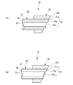
図2(A)および(B)には、第1実施形態にかかる光ファイバの接続端末の別の例が示されている。
図2(A)に示すように、仮に光ファイバ20がフェルール端面30aに対して突き出していたとしても、コア部23の端面23aがクラッド部24の端面24aより凹んでいればこれでもよい。これにより、相手フェルール30との接続において、両光ファイバ20、20のコア部端面23a間に隙間が形成され、両コア部23、23には押圧力が作用しないので、安定した固定状態を維持することができるとともに、長期的な押圧力により劣化や変形が生じるのを抑えことができる。
あるいは、図2(B)に示すように、クラッド部24の端面24aおよび被覆21の端面21aがフェルール30の端面30aと同じ面で、コア部23の端面23aだけがクラッド部24の端面24aおよび被覆21の端面21aよりも凹んでいてもよい。
FIGS. 2A and 2B show another example of an optical fiber connection terminal according to the first embodiment.
As shown in FIG. 2A, even if the
Alternatively, as shown in FIG. 2B, the
次に、図3に基づいて、本発明の第1実施形態にかかる光ファイバの接続方法について説明する。
図3(A)に示すように、少なくとも一方の光ファイバ20の接続端面22が前述した接続端末10で構成されている光ファイバ20を他の光ファイバ20Bと接続する光ファイバの接続方法であって、被覆21付きの前記光ファイバ20の接続端面22を光軸直交面に対して傾斜した面状に形成するとともに、他の光ファイバ20Bの接続端面22も同様に形成して、前記光ファイバ同士20、20Bの前記光軸BLが略一直線となるように各光ファイバ20、20Bの接続端面22、22同士を突き合せることで、前記光ファイバ20、20Bのコア端面23a間に隙間25、25を設ける。
なお、図3(A)においては、他方の光ファイバ20Bにも前述した接続端末10で構成されている光ファイバ20と同じものを用いた場合を示してあるが、この他、図3(B)に示すように、他方の光ファイバ20Bとして、前述した端末処理をしていない通常の光ファイバを用いることもできる。
Next, an optical fiber connecting method according to the first embodiment of the present invention will be described with reference to FIG.
As shown in FIG. 3A, there is an optical fiber connection method in which the connection end face 22 of at least one
3A shows a case where the same
以上、前述した光ファイバの接続端末およびその接続方法によれば、被覆21付きの光ファイバ20をガイド穴31に挿嵌して固定するので、被覆21を除去する工程を省くことができるとともに、被覆21を除去した際のガラス部分の損傷を防止することによりコスト低減を図ることができる。また、接続端面22のコア部23は接続端面22から例えば5μm以上、50μm以下凹んで最初からPC接続させない接続形態であるので、接続端面22同士を押圧する必要がなく、押圧力による長期間の劣化・変形を防止して長期的な信頼性を向上することができる。仮に長期的劣化や環境変化があったとしても常に非PC接続状態であることを維持することにより光伝送特性へ影響を与える可能性のある変動成分を最小限に抑え、伝送システム系全体を長期的に安全に運用することが可能となり、信頼性を高めることができる。さらに、光ファイバ20の接続端面22は光軸直交面に対して傾斜しているので、反射損失の影響を抑えることができる。なお、ガラスに比ベて低ヤング率である被覆21部を介して光ファイバ20のガラス部をフェルール30に固定する形となるが、接続においてPC接続のような押圧力をガラス部が受ける事が無いため、安定したファイバ固定状態を維持できる。
As described above, according to the optical fiber connection terminal and the connection method described above, the
次に、第2実施形態に付いて説明する。
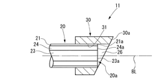
図4には第2実施形態にかかる光ファイバの接続端末が示されている。なお、前述した第1実施形態にかかる光ファイバの接続端末と共通する部位には同じ符号を付して、重複する説明を省略することとする。
Next, a second embodiment will be described.
FIG. 4 shows an optical fiber connection terminal according to the second embodiment. In addition, the same code | symbol is attached | subjected to the site | part common to the connection terminal of the optical fiber concerning 1st Embodiment mentioned above, and the overlapping description is abbreviate | omitted.
この光ファイバの接続端末11では、光ファイバ20を配列するフェルール30のガイド穴31内に被覆21付きの光ファイバ20が固定される光ファイバの接続端末11であって、前記接続端末11のフェルール30の接続端面(端面)30aは光軸BL直交面に対して傾斜した面として形成され、且つ、光ファイバ端面20aは接続端面30aより後退したガイド穴に位置している。
すなわち、光ファイバ20の端面20aは、光軸BLに対し直角に形成されており、一方、フェルール30の端面30aは光軸BL直交面に対して傾斜して形成されているので、光ファイバ20をフェルール30のガイド穴31に挿入すると、光ファイバ20の前方(図4では右方)に隙間26が形成されることになる。
This optical
That is, the
次に、本発明の第2実施形態にかかる光ファイバの接続方法について説明する。
図5に示すように、一方が請求項6に記載の接続端末11で、他方の接続端末12における光ファイバ27の端面27aはフェルール30の接続端面(端面)28と同様に光軸BLの直交面に対して傾斜して形成されており、前記両接続端末11、12を接続する光ファイバの接続方法であって、前記両光ファイバ20、27の光軸BLが略一直線となるように前記両接続端末11、12を付き合わせ、前記両光ファイバ20、27のコア部端面23a間に隙間26を設ける。
Next, an optical fiber connection method according to the second embodiment of the present invention will be described.
As shown in FIG. 5, one is the
以上、前述した光ファイバの接続端末およびその接続方法によれば、接続端末11における光ファイバ20の端面20aを除く部分は光軸BL直交面に対して傾斜して設けられるとともに、光ファイバ20の端面20aは接続端面22よりも後退しているので、光ファイバ20と光ファイバ27は直接接触せずに、両光ファイバ端面20a間には隙間26が設けられて非PC接続となっている。このため、接続端面同士22、28を押圧する必要がなく、押圧力による長期間の劣化・変形を防止して長期的な信頼性を向上することができる。
As described above, according to the optical fiber connection terminal and the connection method described above, the portion of the
なお、本発明の光ファイバの接続端末およびその接続方法は、前述した各実施形態に限定されるものでなく、適宜な変形,改良等が可能である。 Note that the optical fiber connection terminal and the connection method thereof according to the present invention are not limited to the above-described embodiments, and appropriate modifications and improvements can be made.
以上のように、本発明に係る光ファイバの接続端末およびその接続方法は、被覆付きの光ファイバをガイド穴に挿嵌して固定するので、従来のように被覆を除去する必要がなく被覆を除去する工程を省くことができるとともに、被覆を除去した際のガラス部分の損傷を防止することによりコスト低減を図ることができる。また、接続端面のコア部は接続端面から後退して非PC接続となっているので、接続端面同士を押圧する必要がなく、押圧力による長期間の劣化・変形を防止して長期的な信頼性を向上することができる。なお、光ファイバの接続端面は光軸直交面に対して傾斜しているので、反射損失の影響を抑えることができるという効果を有し、光ファイバの接続端末およびその接続方法等として有用である。 As described above, since the optical fiber connection terminal and the connection method thereof according to the present invention insert and fix the coated optical fiber in the guide hole, the coating does not need to be removed as in the conventional case. The removal step can be omitted, and the cost can be reduced by preventing the glass portion from being damaged when the coating is removed. In addition, since the core part of the connection end face is retracted from the connection end face and is not connected to the PC, it is not necessary to press the connection end faces, preventing long-term deterioration and deformation due to the pressing force, and long-term reliability. Can be improved. Since the connection end face of the optical fiber is inclined with respect to the plane orthogonal to the optical axis, it has the effect of suppressing the influence of reflection loss, and is useful as an optical fiber connection terminal and its connection method. .
10 接続端末
20 光ファイバ
20B 他の光ファイバ
21 被覆
22 接続端面
23 コア部
23a 端面
24 クラッド部
25 隙間
31 ガイド穴
BL 光軸
DESCRIPTION OF
Claims (3)
被覆付きの光ファイバ同士を接続するため、前記接続端末のフェルールの接続端面は光軸直交面に対して傾斜した面として形成され、且つ、接続される前記一対の光ファイバは、いずれも、光ファイバ端面が被覆付きのまま光軸直交面に対して傾斜した接続端面とし前記フェルールの接続端面より5μm以上50μm以下後退し、さらに、接続される光ファイバ同士の間隔を50μm以下にして前記ガイド穴の位置に位置するように前記ガイド穴に挿入固定されることを特徴とする光ファイバの接続端末。 An optical fiber connection terminal in which a coated optical fiber is fixed in a guide hole of a ferrule that arranges optical fibers,
In order to connect the coated optical fibers to each other, the connection end face of the ferrule of the connection terminal is formed as a surface inclined with respect to the optical axis orthogonal plane, and both of the pair of optical fibers to be connected are optical The guide hole is formed with a connection end face inclined with respect to the optical axis orthogonal plane while the fiber end face is covered , retreated 5 μm or more and 50 μm or less from the connection end face of the ferrule , and further, the interval between the optical fibers to be connected is 50 μm or less. An optical fiber connection terminal, wherein the optical fiber connection terminal is fixedly inserted into the guide hole so as to be positioned at the position of the optical fiber.
Priority Applications (1)
| Application Number | Priority Date | Filing Date | Title |
|---|---|---|---|
| JP2005253776A JP4635786B2 (en) | 2005-09-01 | 2005-09-01 | Optical fiber connection terminal |
Applications Claiming Priority (1)
| Application Number | Priority Date | Filing Date | Title |
|---|---|---|---|
| JP2005253776A JP4635786B2 (en) | 2005-09-01 | 2005-09-01 | Optical fiber connection terminal |
Publications (2)
| Publication Number | Publication Date |
|---|---|
| JP2007065490A JP2007065490A (en) | 2007-03-15 |
| JP4635786B2 true JP4635786B2 (en) | 2011-02-23 |
Family
ID=37927743
Family Applications (1)
| Application Number | Title | Priority Date | Filing Date |
|---|---|---|---|
| JP2005253776A Expired - Fee Related JP4635786B2 (en) | 2005-09-01 | 2005-09-01 | Optical fiber connection terminal |
Country Status (1)
| Country | Link |
|---|---|
| JP (1) | JP4635786B2 (en) |
Families Citing this family (7)
| Publication number | Priority date | Publication date | Assignee | Title |
|---|---|---|---|---|
| JP5099681B2 (en) | 2007-06-29 | 2012-12-19 | ジーイー・メディカル・システムズ・グローバル・テクノロジー・カンパニー・エルエルシー | Ultrasonic probe, ultrasonic diagnostic apparatus, and method for estimating surface temperature of ultrasonic probe |
| JP6403444B2 (en) * | 2014-06-06 | 2018-10-10 | 三菱電機株式会社 | Mica tape and stator coil |
| US10444439B2 (en) | 2015-10-26 | 2019-10-15 | Sumitomo Electric Industries, Ltd. | Optical connector and optical coupling structure |
| JP6597439B2 (en) * | 2016-03-24 | 2019-10-30 | 住友電気工業株式会社 | Optical connector ferrule, optical connector and optical coupling structure |
| JPWO2017195636A1 (en) * | 2016-05-12 | 2019-03-14 | 住友電気工業株式会社 | Optical connector and optical coupling structure |
| JP2019144510A (en) * | 2018-02-23 | 2019-08-29 | 住友電気工業株式会社 | Optical connector, optical connection structure and method for manufacturing optical connector |
| JP7578393B2 (en) * | 2019-08-02 | 2024-11-06 | 住友電気工業株式会社 | Optical Connector |
Family Cites Families (20)
| Publication number | Priority date | Publication date | Assignee | Title |
|---|---|---|---|---|
| JPS58139108A (en) * | 1982-02-12 | 1983-08-18 | Nippon Telegr & Teleph Corp <Ntt> | Connecting method of optical fiber core |
| JPS6463910A (en) * | 1987-09-04 | 1989-03-09 | Mitsubishi Rayon Co | Optical fiber with integrated optical connector plug |
| JPH0626885Y2 (en) * | 1989-05-29 | 1994-07-20 | 東海ゴム工業株式会社 | Connector for optical fiber |
| JPH0497106A (en) * | 1990-08-10 | 1992-03-30 | Nippon Telegr & Teleph Corp <Ntt> | Optical fiber terminal and optical connector with low reflection and manufacture of optical fiber terminal with low reflection |
| JPH0588041A (en) * | 1991-09-30 | 1993-04-09 | Nippon Telegr & Teleph Corp <Ntt> | Optical fiber optical connection circuit |
| JP2896947B2 (en) * | 1991-10-18 | 1999-05-31 | 京セラ株式会社 | Optical fiber end structure and method of manufacturing the same |
| JPH06294911A (en) * | 1993-04-08 | 1994-10-21 | Toray Ind Inc | Optical fixed attenuator and manufacturing method thereof |
| JP3518089B2 (en) * | 1994-09-16 | 2004-04-12 | 東レ株式会社 | Broadband optical fiber, its core, cord, and optical fiber with connector, cord |
| JP2847619B2 (en) * | 1994-09-26 | 1999-01-20 | ヒロセ電機株式会社 | Variable optical attenuator |
| JPH08304673A (en) * | 1995-03-07 | 1996-11-22 | Toray Ind Inc | Single-mode optical fiber, its core wire, cord, and optical fiber core wire with connector, cord |
| JPH09127360A (en) * | 1995-11-02 | 1997-05-16 | Omron Corp | Optical fiber connecting device, optical fiber optical coupling method, optical fiber cable and optical element manufacturing method |
| US6074100A (en) * | 1998-07-30 | 2000-06-13 | Sikorsky Aircraft Corporation | Fiber optic terminus and manufacturing method therefor |
| JP3501969B2 (en) * | 1999-02-12 | 2004-03-02 | 住友電気工業株式会社 | Optical fiber array and optical waveguide |
| JP2000298225A (en) * | 1999-04-13 | 2000-10-24 | Mitsubishi Rayon Co Ltd | Optical connector plug and optical cable connection method |
| US6142678A (en) * | 1999-06-15 | 2000-11-07 | Jds Uniphase Inc. | Optical coupling |
| JP2003195128A (en) * | 2001-12-28 | 2003-07-09 | Showa Electric Wire & Cable Co Ltd | Fiber for light signal attenuation |
| JP2003322760A (en) * | 2002-04-30 | 2003-11-14 | Totoku Electric Co Ltd | Method of manufacturing optical fiber assembly and optical fiber assembly |
| JP2003344699A (en) * | 2002-05-29 | 2003-12-03 | Showa Electric Wire & Cable Co Ltd | Optical connector member |
| JP2004177947A (en) * | 2002-11-11 | 2004-06-24 | Pentax Corp | Optical communication device |
| JP2004258193A (en) * | 2003-02-25 | 2004-09-16 | Totoku Electric Co Ltd | Method of manufacturing optical fiber assembly and optical fiber assembly |
-
2005
- 2005-09-01 JP JP2005253776A patent/JP4635786B2/en not_active Expired - Fee Related
Also Published As
| Publication number | Publication date |
|---|---|
| JP2007065490A (en) | 2007-03-15 |
Similar Documents
| Publication | Publication Date | Title |
|---|---|---|
| US10605993B2 (en) | Optical connection component | |
| US7756370B2 (en) | Method of producing a ferrule with an optical fiber | |
| JP3273490B2 (en) | Multi-core microcapillary and method for connecting optical waveguide circuit and optical fiber using the same | |
| JP3821971B2 (en) | Fiber optic array | |
| JP4635786B2 (en) | Optical fiber connection terminal | |
| CN112352173B (en) | Optical path bending connector and optical path bending connector assembly | |
| JP5074806B2 (en) | Assembly method of mechanical splice | |
| JP7435692B2 (en) | How to connect optical connectors | |
| JP5074805B2 (en) | Assembly method of mechanical splice | |
| JP4349372B2 (en) | Optical module and optical module manufacturing method | |
| KR101094314B1 (en) | POF optical connector using large diameter zirconia capillary and its manufacturing method | |
| JPH07225325A (en) | Non-reflective end of optical fiber | |
| WO2024142472A1 (en) | Optical fiber holding component and ferrule assembly | |
| JPH09105838A (en) | Optical waveguide device | |
| JP3270858B2 (en) | Optical fiber connection device | |
| CN102549463A (en) | Optical fiber connected body and method for producing same | |
| JPS61132911A (en) | Optical connector plug | |
| JPH0233110A (en) | Optical connector | |
| JP4576163B2 (en) | Optical connection method | |
| JP2006011255A (en) | Optical connector ferrule and optical connector | |
| JPH08313762A (en) | Optical connector plug | |
| JP2004191915A (en) | Optical connector | |
| CN100526926C (en) | Method of manufacture bush with optical fiber | |
| JPH10282370A (en) | Optical module and manufacturing method thereof | |
| JPH05288963A (en) | Waveguide device |
Legal Events
| Date | Code | Title | Description |
|---|---|---|---|
| A621 | Written request for application examination |
Free format text: JAPANESE INTERMEDIATE CODE: A621 Effective date: 20080619 |
|
| A977 | Report on retrieval |
Free format text: JAPANESE INTERMEDIATE CODE: A971007 Effective date: 20100422 |
|
| A131 | Notification of reasons for refusal |
Free format text: JAPANESE INTERMEDIATE CODE: A131 Effective date: 20100427 |
|
| A521 | Request for written amendment filed |
Free format text: JAPANESE INTERMEDIATE CODE: A523 Effective date: 20100622 |
|
| A131 | Notification of reasons for refusal |
Free format text: JAPANESE INTERMEDIATE CODE: A131 Effective date: 20100831 |
|
| A521 | Request for written amendment filed |
Free format text: JAPANESE INTERMEDIATE CODE: A523 Effective date: 20101001 |
|
| TRDD | Decision of grant or rejection written | ||
| A01 | Written decision to grant a patent or to grant a registration (utility model) |
Free format text: JAPANESE INTERMEDIATE CODE: A01 Effective date: 20101026 |
|
| A01 | Written decision to grant a patent or to grant a registration (utility model) |
Free format text: JAPANESE INTERMEDIATE CODE: A01 |
|
| A61 | First payment of annual fees (during grant procedure) |
Free format text: JAPANESE INTERMEDIATE CODE: A61 Effective date: 20101108 |
|
| FPAY | Renewal fee payment (event date is renewal date of database) |
Free format text: PAYMENT UNTIL: 20131203 Year of fee payment: 3 |
|
| R150 | Certificate of patent or registration of utility model |
Free format text: JAPANESE INTERMEDIATE CODE: R150 Ref document number: 4635786 Country of ref document: JP Free format text: JAPANESE INTERMEDIATE CODE: R150 |
|
| R250 | Receipt of annual fees |
Free format text: JAPANESE INTERMEDIATE CODE: R250 |
|
| R250 | Receipt of annual fees |
Free format text: JAPANESE INTERMEDIATE CODE: R250 |
|
| R250 | Receipt of annual fees |
Free format text: JAPANESE INTERMEDIATE CODE: R250 |
|
| R250 | Receipt of annual fees |
Free format text: JAPANESE INTERMEDIATE CODE: R250 |
|
| R250 | Receipt of annual fees |
Free format text: JAPANESE INTERMEDIATE CODE: R250 |
|
| R250 | Receipt of annual fees |
Free format text: JAPANESE INTERMEDIATE CODE: R250 |
|
| R250 | Receipt of annual fees |
Free format text: JAPANESE INTERMEDIATE CODE: R250 |
|
| R250 | Receipt of annual fees |
Free format text: JAPANESE INTERMEDIATE CODE: R250 |
|
| R250 | Receipt of annual fees |
Free format text: JAPANESE INTERMEDIATE CODE: R250 |
|
| LAPS | Cancellation because of no payment of annual fees |