JP4635652B2 - Image processing apparatus, image processing method, program for image processing method, and recording medium recording program for image processing method - Google Patents
Image processing apparatus, image processing method, program for image processing method, and recording medium recording program for image processing method Download PDFInfo
- Publication number
- JP4635652B2 JP4635652B2 JP2005063336A JP2005063336A JP4635652B2 JP 4635652 B2 JP4635652 B2 JP 4635652B2 JP 2005063336 A JP2005063336 A JP 2005063336A JP 2005063336 A JP2005063336 A JP 2005063336A JP 4635652 B2 JP4635652 B2 JP 4635652B2
- Authority
- JP
- Japan
- Prior art keywords
- image data
- pixel
- intersection
- pixel value
- image processing
- Prior art date
- Legal status (The legal status is an assumption and is not a legal conclusion. Google has not performed a legal analysis and makes no representation as to the accuracy of the status listed.)
- Expired - Fee Related
Links
Images


Classifications
-
- G—PHYSICS
- G06—COMPUTING OR CALCULATING; COUNTING
- G06T—IMAGE DATA PROCESSING OR GENERATION, IN GENERAL
- G06T3/00—Geometric image transformations in the plane of the image
- G06T3/40—Scaling of whole images or parts thereof, e.g. expanding or contracting
- G06T3/403—Edge-driven scaling; Edge-based scaling
Landscapes
- Physics & Mathematics (AREA)
- General Physics & Mathematics (AREA)
- Engineering & Computer Science (AREA)
- Theoretical Computer Science (AREA)
- Image Processing (AREA)
- Editing Of Facsimile Originals (AREA)
- Image Analysis (AREA)
Description
本発明は、画像処理装置、画像処理方法、画像処理方法のプログラム及び画像処理方法のプログラムを記録した記録媒体に関し、例えば解像度の変換に適用することができる。本発明は、画素値の勾配が最も大きなエッジ勾配方向に直交するエッジ方向を検出し、このエッジ方向の交点に基づいて画素値を補正することにより、丸まった角を尖らせることができるようにする。 The present invention relates to an image processing apparatus, an image processing method, a program for the image processing method, and a recording medium on which the program for the image processing method is recorded, and can be applied to, for example, resolution conversion. The present invention detects an edge direction orthogonal to the edge gradient direction having the largest pixel value gradient, and corrects the pixel value based on the intersection of the edge directions so that a rounded corner can be sharpened. To do.
従来、画像処理においては、例えば線型補間処理、バイキュービック変換処理により、画像を拡大、縮小するようになされており、例えば特開2003−224715号公報には、このような画像処理を簡易な構成により実行する方法が提案されている。またこのような画像処理のうち、画像の拡大においては、高域強調、エンハンス等の処理により、いわゆるぼけを低減するようになされている。 Conventionally, in image processing, an image is enlarged or reduced by, for example, linear interpolation processing or bicubic conversion processing. For example, Japanese Patent Application Laid-Open No. 2003-224715 discloses a simple configuration of such image processing. A method of executing is proposed. Of such image processing, when enlarging an image, so-called blur is reduced by processing such as high-frequency emphasis and enhancement.
しかしながら従来手法により画像を拡大する場合、元の画像では尖った角が丸まってしまい、これら高域強調、エンハンス等の処理を実行しても、このような丸まった角については元に戻すことが困難であり、結局、画質が劣化する問題がある。
本発明は以上の点を考慮してなされたもので、丸まった角を尖らせることができる画像処理装置、画像処理方法、画像処理方法のプログラム及び画像処理方法のプログラムを記録した記録媒体を提案しようとするものである。 The present invention has been made in view of the above points, and proposes an image processing apparatus capable of sharpening rounded corners, an image processing method, a program for the image processing method, and a recording medium on which the program for the image processing method is recorded. It is something to try.
かかる課題を解決するため本発明のある観点によれば、入力画像データを処理して出力画像データを出力する画像処理装置に適用して、前記入力画像データの各画素毎に、画素値の勾配が最も大きなエッジ勾配方向と直交するエッジ方向を検出する勾配解析部と、前記勾配解析部により検出される前記エッジ方向に基づいて、前記出力画像データの各画素毎に、前記エッジ方向の直線と周辺画素の前記エッジ方向の直線との間で交点を検出する交点検出部と、前記出力画像データの各画素毎に、前記交点検出部で検出される前記交点に応じて、前記入力画像データによる画素値を補正して前記交点の側に角を尖らせる角改善部と、前記交点の信頼度を検出する信頼度計算部と、前記信頼度に応じて、前記入力画像データによる画素値を前記角改善部による画素値により補正して前記出力画像データを出力するブレンド部とを備えるようにする。 In order to solve such a problem , according to one aspect of the present invention, it is applied to an image processing apparatus that processes input image data and outputs output image data, and a gradient of a pixel value for each pixel of the input image data. A gradient analyzer that detects an edge direction orthogonal to the largest edge gradient direction, and a straight line in the edge direction for each pixel of the output image data based on the edge direction detected by the gradient analyzer. According to the input image data according to the intersection detected by the intersection detection unit for each pixel of the output image data, and an intersection detection unit for detecting an intersection between the peripheral pixels and the straight line in the edge direction. A corner improvement unit that corrects a pixel value and sharpens a corner toward the intersection, a reliability calculation unit that detects a reliability of the intersection, and a pixel value based on the input image data according to the reliability Corner Is corrected by the pixel value by the good section so as and a blending unit for outputting the output image data.
また本発明の他の観点によれば、入力画像データを処理して出力画像データを出力する画像処理装置に適用して、それぞれ前記入力画像データを処理して画像データを出力する複数の画像処理部と、前記複数の画像処理部から出力される前記画像データを合成して前記出力画像データを生成する統合部とを備え、前記画像処理部は、前記入力画像データの各画素毎に、画素値の勾配が最も大きなエッジ勾配方向と直交するエッジ方向を検出する勾配解析部と、前記勾配解析部により検出される前記エッジ方向に基づいて、前記出力画像データの各画素毎に、前記エッジ方向の直線と周辺画素の前記エッジ方向の直線との間で交点を検出する交点検出部と、前記入力画像データの解像度を変換して出力データを出力する解像度変換部と、前記出力画像データの各画素毎に、前記交点検出部で検出される前記交点に応じて、前記解像度変換部の出力データによる画素値を補正して前記交点の側に角を尖らせる角改善部と、前記交点の信頼度を検出する信頼度計算部と、前記信頼度に応じて、前記出力データの画素値を前記角改善部による画素値により補正して前記画像データを出力するブレンド部とを有し、前記複数の画像処理部は、前記エッジ方向の検出に供する特性が異なる特性に設定されているようにする。 According to another aspect of the present invention, the present invention is applied to an image processing apparatus that processes input image data and outputs output image data, and processes each of the input image data and outputs image data. And an integration unit that combines the image data output from the plurality of image processing units to generate the output image data. The image processing unit includes a pixel for each pixel of the input image data. A gradient analysis unit that detects an edge direction orthogonal to an edge gradient direction having the largest value gradient, and the edge direction for each pixel of the output image data based on the edge direction detected by the gradient analysis unit An intersection detection unit that detects an intersection between the straight line in the edge direction and a straight line in the edge direction of the surrounding pixels, a resolution conversion unit that converts the resolution of the input image data and outputs output data, and the output For each pixel of the image data, according to the intersection detected by the intersection detection unit, a corner improvement unit that corrects a pixel value by output data of the resolution conversion unit and sharpens the corner toward the intersection, A reliability calculation unit that detects the reliability of the intersection point, and a blend unit that outputs the image data by correcting the pixel value of the output data with the pixel value of the angle improvement unit according to the reliability. The plurality of image processing units are set to have different characteristics for use in detection of the edge direction.
また本発明の他の観点によれば、入力画像データを処理して出力画像データを出力する画像処理方法に適用して、前記入力画像データの各画素毎に、画素値の勾配が最も大きなエッジ勾配方向と直交するエッジ方向を検出する勾配解析のステップと、前記勾配解析のステップにより検出される前記エッジ方向に基づいて、前記出力画像データの各画素毎に、前記エッジ方向の直線と周辺画素の前記エッジ方向の直線との間で交点を検出する交点検出のステップと、前記出力画像データの各画素毎に、前記交点検出のステップで検出される前記交点に応じて、前記入力画像データによる画素値を補正して前記交点の側に角を尖らせる角改善のステップと、前記交点の信頼度を検出する信頼度計算のステップと、前記信頼度に応じて、前記入力画像データによる画素値を前記角改善のステップによる画素値により補正して前記出力画像データを出力するブレンドのステップとを有するようにする。 According to another aspect of the present invention, an edge is applied to an image processing method that processes input image data and outputs output image data, and has the largest pixel value gradient for each pixel of the input image data. A step of gradient analysis for detecting an edge direction orthogonal to the gradient direction, and a straight line and peripheral pixels in the edge direction for each pixel of the output image data based on the edge direction detected by the step of gradient analysis An intersection detection step for detecting an intersection point with the straight line in the edge direction, and for each pixel of the output image data, according to the intersection point detected in the intersection detection step, the input image data A step of improving the angle by correcting the pixel value to sharpen the corner toward the side of the intersection, a step of calculating the reliability for detecting the reliability of the intersection, and the input image according to the reliability The pixel value by the data corrected by the pixel value in step of the angle improvement to have a step of blending outputting the output image data.
また本発明の他の観点によれば、入力画像データを処理して出力画像データを出力する画像処理方法に適用して、それぞれ前記入力画像データを処理して画像データを出力する複数の画像処理のステップと、前記複数の画像処理のステップから出力される前記画像データを合成して前記出力画像データを生成する統合のステップとを備え、前記画像処理のステップは、前記入力画像データの各画素毎に、画素値の勾配が最も大きなエッジ勾配方向と直交するエッジ方向を検出する勾配解析のステップと、前記勾配解析のステップにより検出される前記エッジ方向に基づいて、前記出力画像データの各画素毎に、前記エッジ方向の直線と周辺画素の前記エッジ方向の直線との間で交点を検出する交点検出のステップと、前記入力画像データの解像度を変換して出力データを出力する解像度変換のステップと、前記出力画像データの各画素毎に、前記交点検出のステップで検出される前記交点に応じて、前記解像度変換のステップの出力データによる画素値を補正して前記交点の側に角を尖らせる角改善のステップと、前記交点の信頼度を検出する信頼度計算のステップと、前記信頼度に応じて、前記出力データの画素値を前記角改善のステップによる画素値により補正して前記画像データを出力するブレンドのステップとを有し、前記複数の画像処理のステップは、前記エッジ方向の検出に供する特性が異なる特性に設定されているようにする。 According to another aspect of the present invention, the present invention is applied to an image processing method that processes input image data and outputs output image data, and processes each of the input image data and outputs image data. And an integration step of generating the output image data by synthesizing the image data output from the plurality of image processing steps, and the image processing step includes each pixel of the input image data. For each pixel of the output image data, a gradient analysis step for detecting an edge direction orthogonal to an edge gradient direction having the largest pixel value gradient and the edge direction detected by the gradient analysis step is performed. A step of detecting an intersection between the straight line in the edge direction and the straight line in the edge direction of surrounding pixels, and a solution of the input image data The resolution conversion step of converting the degree and outputting the output data, and the output data of the resolution conversion step according to the intersection detected in the intersection detection step for each pixel of the output image data The step of improving the angle by correcting the pixel value to sharpen the corner toward the intersection, the step of calculating the reliability for detecting the reliability of the intersection, and the pixel value of the output data according to the reliability And a blending step of outputting the image data after correcting by the pixel value in the corner improvement step, wherein the plurality of image processing steps are set to different characteristics for use in detecting the edge direction. To be.
また本発明の他の観点によれば、演算処理手段による実行により、入力画像データを処理して出力画像データを出力する画像処理方法のプログラムに適用して、前記入力画像データの各画素毎に、画素値の勾配が最も大きなエッジ勾配方向と直交するエッジ方向を検出する勾配解析のステップと、前記勾配解析のステップにより検出される前記エッジ方向に基づいて、前記出力画像データの各画素毎に、前記エッジ方向の直線と周辺画素の前記エッジ方向の直線との間で交点を検出する交点検出のステップと、前記出力画像データの各画素毎に、前記交点検出のステップで検出される前記交点に応じて、前記入力画像データによる画素値を補正して前記交点の側に角を尖らせる角改善のステップと、前記交点の信頼度を検出する信頼度計算のステップと、前記信頼度に応じて、前記入力画像データによる画素値を前記角改善のステップによる画素値により補正して前記出力画像データを出力するブレンドのステップとを有するようにする。 According to another aspect of the present invention, the present invention is applied to a program for an image processing method for processing input image data and outputting output image data by execution by an arithmetic processing unit, and for each pixel of the input image data. , A gradient analysis step for detecting an edge direction orthogonal to an edge gradient direction having the largest pixel value gradient, and each pixel of the output image data based on the edge direction detected by the gradient analysis step. A step of detecting an intersection between the straight line in the edge direction and a straight line in the edge direction of peripheral pixels, and the intersection detected in the step of detecting the intersection for each pixel of the output image data. In accordance with the step of improving the pixel value based on the input image data and sharpening the corner toward the intersection, and the reliability calculation for detecting the reliability of the intersection And step, depending on the reliability, the pixel value by the input image data to a step of blending outputting the output image data by correcting the pixel value in step of the angle improvement.
また本発明の他の観点によれば、演算処理手段による実行により、入力画像データを処理して出力画像データを出力する画像処理方法のプログラムに適用して、それぞれ前記入力画像データを処理して画像データを出力する複数の画像処理のステップと、前記複数の画像処理のステップから出力される前記画像データを合成して前記出力画像データを生成する統合のステップとを備え、前記画像処理のステップは、前記入力画像データの各画素毎に、画素値の勾配が最も大きなエッジ勾配方向と直交するエッジ方向を検出する勾配解析のステップと、前記勾配解析のステップにより検出される前記エッジ方向に基づいて、前記出力画像データの各画素毎に、前記エッジ方向の直線と周辺画素の前記エッジ方向の直線との間で交点を検出する交点検出のステップと、前記入力画像データの解像度を変換して出力データを出力する解像度変換のステップと、前記出力画像データの各画素毎に、前記交点検出のステップで検出される前記交点に応じて、前記解像度変換のステップの出力データによる画素値を補正して前記交点の側に角を尖らせる角改善のステップと、前記交点の信頼度を検出する信頼度計算のステップと、前記信頼度に応じて、前記出力データの画素値を前記角改善のステップによる画素値により補正して前記画像データを出力するブレンドのステップとを有し、前記複数の画像処理のステップは、前記エッジ方向の検出に供する特性が異なる特性に設定されているようにする。 According to another aspect of the present invention , the input image data is processed by execution by the arithmetic processing means and applied to a program of an image processing method for outputting output image data, and each of the input image data is processed. A plurality of image processing steps for outputting image data; and an integration step for generating the output image data by combining the image data output from the plurality of image processing steps. Is based on the gradient analysis step for detecting the edge direction orthogonal to the edge gradient direction having the largest pixel value gradient for each pixel of the input image data, and the edge direction detected by the gradient analysis step. For each pixel of the output image data, an intersection is detected between the straight line in the edge direction and the straight line in the edge direction of surrounding pixels. In accordance with the intersection detected in the intersection detection step for each pixel of the output image data, a detection conversion step, a resolution conversion step of converting the resolution of the input image data and outputting output data The step of improving the angle by correcting the pixel value based on the output data of the step of converting the resolution to sharpen the corner toward the side of the intersection, the step of calculating the reliability to detect the reliability of the intersection, and the reliability And a blending step of outputting the image data by correcting the pixel value of the output data with the pixel value in the corner improvement step, wherein the plurality of image processing steps include detecting the edge direction. Make sure that the characteristics provided for are set to different characteristics.
また本発明の他の観点によれば、演算処理手段による実行により、入力画像データを処理して出力画像データを出力する画像処理方法のプログラムを記録した記録媒体に適用して、前記画像処理方法のプログラムは、前記入力画像データの各画素毎に、画素値の勾配が最も大きなエッジ勾配方向と直交するエッジ方向を検出する勾配解析のステップと、前記勾配解析のステップにより検出される前記エッジ方向に基づいて、前記出力画像データの各画素毎に、前記エッジ方向の直線と周辺画素の前記エッジ方向の直線との間で交点を検出する交点検出のステップと、前記出力画像データの各画素毎に、前記交点検出のステップで検出される前記交点に応じて、前記入力画像データによる画素値を補正して前記交点の側に角を尖らせる角改善のステップと、前記交点の信頼度を検出する信頼度計算のステップと、前記信頼度に応じて、前記入力画像データによる画素値を前記角改善のステップによる画素値により補正して前記出力画像データを出力するブレンドのステップとを有するようにする。 According to another aspect of the present invention, the image processing method is applied to a recording medium recorded with a program of an image processing method for processing input image data and outputting output image data by execution by an arithmetic processing means. For each pixel of the input image data, a gradient analysis step for detecting an edge direction orthogonal to an edge gradient direction having the largest pixel value gradient, and the edge direction detected by the gradient analysis step For each pixel of the output image data, a step of detecting an intersection point between the straight line in the edge direction and the straight line in the edge direction of peripheral pixels, and for each pixel of the output image data Further, in accordance with the intersection detected in the intersection detection step, the pixel value based on the input image data is corrected to sharpen the corner toward the intersection. And a reliability calculation step of detecting the reliability of the intersection, and the output image data is corrected by correcting the pixel value based on the input image data with the pixel value based on the angle improvement step according to the reliability. Output blending step.
また本発明の他の観点によれば、演算処理手段による実行により、入力画像データを処理して出力画像データを出力する画像処理方法のプログラム記録した記録媒体に適用して、前記画像処理方法のプログラムは、それぞれ前記入力画像データを処理して画像データを出力する複数の画像処理のステップと、前記複数の画像処理のステップから出力される前記画像データを合成して前記出力画像データを生成する統合のステップとを備え、前記画像処理のステップは、前記入力画像データの各画素毎に、画素値の勾配が最も大きなエッジ勾配方向と直交するエッジ方向を検出する勾配解析のステップと、前記勾配解析のステップにより検出される前記エッジ方向に基づいて、前記出力画像データの各画素毎に、前記エッジ方向の直線と周辺画素の前記エッジ方向の直線との間で交点を検出する交点検出のステップと、前記入力画像データの解像度を変換して出力データを出力する解像度変換のステップと、前記出力画像データの各画素毎に、前記交点検出のステップで検出される前記交点に応じて、前記解像度変換のステップの出力データによる画素値を補正して前記交点の側に角を尖らせる角改善のステップと、前記交点の信頼度を検出する信頼度計算のステップと、前記信頼度に応じて、前記出力データの画素値を前記角改善のステップによる画素値により補正して前記画像データを出力するブレンドのステップとを有し、前記複数の画像処理のステップは、前記エッジ方向の検出に供する特性が異なる特性に設定されているようにする。 According to another aspect of the present invention, the image processing method is applied to a recording medium recorded with a program of an image processing method for processing input image data and outputting output image data by execution by an arithmetic processing means. The program generates the output image data by combining the plurality of image processing steps for processing the input image data and outputting the image data, and the image data output from the plurality of image processing steps. A step of gradient analysis for detecting, for each pixel of the input image data, an edge direction orthogonal to an edge gradient direction having the largest gradient of the pixel value for each pixel of the input image data; Based on the edge direction detected by the analysis step, the edge direction straight line and the peripheral image for each pixel of the output image data. An intersection detection step for detecting an intersection with the straight line in the edge direction, a resolution conversion step for converting the resolution of the input image data and outputting output data, and for each pixel of the output image data An angle improvement step of correcting a pixel value based on output data of the resolution conversion step and sharpening an angle toward the intersection according to the intersection detected in the intersection detection step; and reliability of the intersection A reliability calculation step of detecting a degree, and a blending step of correcting the pixel value of the output data with the pixel value in the angle improvement step and outputting the image data according to the reliability. In the plurality of image processing steps, characteristics used for detection of the edge direction are set to different characteristics.
第1の観点に係る構成により、入力画像データを処理して出力画像データを出力する画像処理装置に適用して、前記入力画像データの各画素毎に、画素値の勾配が最も大きなエッジ勾配方向と直交するエッジ方向を検出する勾配解析部と、前記勾配解析部により検出される前記エッジ方向に基づいて、前記出力画像データの各画素毎に、前記エッジ方向の直線と周辺画素の前記エッジ方向の直線との間で交点を検出する交点検出部と、前記出力画像データの各画素毎に、前記交点検出部で検出される前記交点に応じて、前記入力画像データによる画素値を補正して前記交点の側に角を尖らせる角改善部と、前記交点の信頼度を検出する信頼度計算部と、前記信頼度に応じて、前記入力画像データによる画素値を前記角改善部による画素値により補正して前記出力画像データを出力するブレンド部とを備えるようにすれば、エッジ方向により検出される交点により角の頂点を検出して、この頂点に向かって角が尖るように画素値を補正することができる。また信頼度を検出してこのような処理結果により画素値を補正して画像データを出力することにより、角であることが確からしくない箇所については、元の入力画像データによる画素値により出力画像データを出力することができ、これにより違和感無く角を尖らせて、画質を向上することができる。 With the configuration according to the first aspect, the present invention is applied to an image processing apparatus that processes input image data and outputs output image data. For each pixel of the input image data, an edge gradient direction having the largest pixel value gradient A gradient analysis unit that detects an edge direction orthogonal to the edge direction, and a straight line of the edge direction and the edge direction of peripheral pixels for each pixel of the output image data based on the edge direction detected by the gradient analysis unit An intersection detection unit that detects an intersection with the straight line, and for each pixel of the output image data, the pixel value based on the input image data is corrected according to the intersection detected by the intersection detection unit. A corner improvement unit that sharpens a corner toward the intersection, a reliability calculation unit that detects the reliability of the intersection, and a pixel value obtained by the input image data according to the reliability According And a blending unit that corrects and outputs the output image data, detects the vertex of the corner from the intersection detected by the edge direction, and corrects the pixel value so that the corner is sharpened toward this vertex can do. In addition, by detecting the reliability and correcting the pixel value based on the processing result and outputting the image data, the output image is output based on the pixel value based on the original input image data for a portion that is not sure to be a corner. Data can be output, thereby sharpening corners and improving image quality.
また第2の観点に係る構成によれば、入力画像データを処理して出力画像データを出力する画像処理装置に適用して、それぞれ前記入力画像データを処理して画像データを出力する複数の画像処理部と、前記複数の画像処理部から出力される前記画像データを合成して前記出力画像データを生成する統合部とを備え、前記画像処理部は、前記入力画像データの各画素毎に、画素値の勾配が最も大きなエッジ勾配方向と直交するエッジ方向を検出する勾配解析部と、前記勾配解析部により検出される前記エッジ方向に基づいて、前記出力画像データの各画素毎に、前記エッジ方向の直線と周辺画素の前記エッジ方向の直線との間で交点を検出する交点検出部と、前記入力画像データの解像度を変換して出力データを出力する解像度変換部と、前記出力画像データの各画素毎に、前記交点検出部で検出される前記交点に応じて、前記解像度変換部の出力データによる画素値を補正して前記交点の側に角を尖らせる角改善部と、前記交点の信頼度を検出する信頼度計算部と、前記信頼度に応じて、前記出力データの画素値を前記角改善部による画素値により補正して前記画像データを出力するブレンド部とを有することにより、この各画像処理部において、違和感無く角を尖らせて、画質を向上することができる。またこのように構成して、前記複数の画像処理部は、前記エッジ方向の検出に供する特性が異なる特性に設定されていることにより、1つの画像処理部でエッジ方向を検出できない場合、誤り検出した場合等であっても、他の画像処理部では、エッジ方向を正しく検出することができ、これにより確実に、画質を向上することができる。 In addition, according to the configuration according to the second aspect, the present invention is applied to an image processing device that processes input image data and outputs output image data, and processes each of the input image data and outputs image data. A processing unit, and an integration unit that generates the output image data by combining the image data output from the plurality of image processing units, the image processing unit, for each pixel of the input image data, A gradient analysis unit that detects an edge direction orthogonal to an edge gradient direction having the largest pixel value gradient, and the edge for each pixel of the output image data based on the edge direction detected by the gradient analysis unit An intersection detection unit that detects an intersection between a straight line in a direction and a straight line in the edge direction of surrounding pixels, a resolution conversion unit that converts the resolution of the input image data and outputs output data, An angle improving unit that corrects a pixel value by output data of the resolution conversion unit and sharpens an angle toward the intersection for each pixel of the output image data according to the intersection detected by the intersection detection unit; A reliability calculation unit that detects the reliability of the intersection, and a blend unit that corrects a pixel value of the output data with a pixel value by the angle improvement unit according to the reliability and outputs the image data. By having this, in each of these image processing units, the corners can be sharpened without a sense of incongruity and the image quality can be improved. Further, the plurality of image processing units are configured in this way, and the error detection is performed when the edge direction cannot be detected by one image processing unit because the characteristics used for the detection of the edge direction are set to different characteristics. Even in such a case, the other image processing units can correctly detect the edge direction, and the image quality can be improved reliably.
これにより第3、第5及び第7の観点に係る構成によれば、違和感無く角を尖らせて、画質を向上することができる画像処理方法、画像処理方法のプログラム及び画像処理方法のプログラムを記録した記録媒体を提供することができる。 Thereby, according to the structure which concerns on a 3rd, 5th and 7th viewpoint, the image processing method which can sharpen a corner without a sense of incongruity, and can improve an image quality, the program of an image processing method, and the program of an image processing method A recorded recording medium can be provided.
また第4、第6及び第8の観点に係る構成によれば、違和感無く角を尖らせて、確実に、画質を向上することができる画像処理方法、画像処理方法のプログラム及び画像処理方 In addition, according to the configurations according to the fourth, sixth, and eighth aspects, the image processing method, the image processing method program, and the image processing method that can sharply improve the image quality without causing a sense of incongruity are provided.
本発明によれば、違和感無く角を尖らせて、画質を向上することができる。 According to the present invention, it is possible to improve the image quality by sharpening the corners without feeling uncomfortable.
以下、適宜図面を参照しながら本発明の実施例を詳述する。 Hereinafter, embodiments of the present invention will be described in detail with reference to the drawings as appropriate.
(1)実施例1の構成
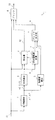
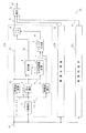
図1は、本発明の実施例に係る画像処理装置を示す機能ブロック図である。この画像処理装置1は、演算処理手段である例えばディジタルシグナルプロセッサにより形成され、この演算処理手段により所定の処理プログラムを実行することにより、入力画像データS1を画像処理して出力画像データS3を表示手段等に出力する。
(1) Configuration of
なおこの実施例において、この演算処理手段に係る処理プログラムにおいては、この画像処理装置1にプリインストールされて提供されるようになされているものの、このような処理プログラムの提供にあっては、例えばインターネット等によるネットワークを介したダウンロードにより提供するようにしてもよく、さらには種々の記録媒体を介して提供するようにしてもよい。なおこのような記録媒体においては、光ディスク、メモリカード、着脱可能なハードディスク装置等、種々の記録媒体に広く適用することができる。
In this embodiment, the processing program related to the arithmetic processing means is preinstalled in the
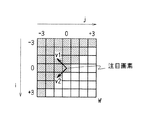
この画像処理装置1において、勾配解析部2は、入力画像データS1の各画素毎に、画素値の勾配が最も大きなエッジ勾配方向、このエッジ勾配方向と直交するエッジ方向を検出する。勾配解析部2は、例えばラスタ走査順に順次注目画素を切り換え、図2に示すように、この注目画素を中心とした範囲Wにおける画素値を用いた演算処理により、次式により表される輝度勾配の行列Gを各画素毎に生成する。なおここで図2は、注目画素を中心にしたx方向及びy方向の±3画素をこの範囲Wに設定した例である。
In the
ここでw(i,j) は、(2)式により表されるガウス型の重みであり、gは、画像輝度Iのx方向の偏微分gx と、画像輝度Iのy方向の偏微分gy とにより(3)式で表される輝度勾配である。 Here w (i, j) is, (2) is the weight of the Gaussian represented by formula, g is the partial derivative g x of the x direction of the image luminance I, in the y direction of the image luminance I PDE by a g y (3) it is a luminance gradient represented by formula.
これにより勾配解析部2は、注目画素を中心とした所定範囲Wについて、注目画素を基準にして重み付け処理してなる画素値の勾配を検出する。
Thereby, the
勾配解析部2は、この輝度勾配の行列Gを処理することにより、図3に示すように、注目画素において、画素値の勾配が最も大きい方向であるエッジ勾配方向v1、このエッジ勾配方向v1に直交する方向であるエッジ方向v2を検出する。またこれらエッジ勾配方向v1、エッジ方向v2について、それぞれ画素値の勾配の分散を示す固有値λ1、λ2を検出する。
As shown in FIG. 3, the
具体的に、勾配解析部2は、次式の演算処理により、エッジ勾配方向v1、エッジ方向v2、固有値λ1、λ2(λ1≧λ2)を検出する。
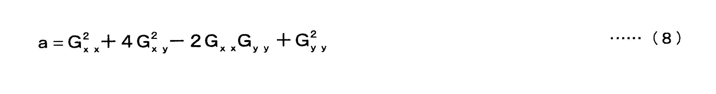
Specifically, the
但し、aは、次式による。 However, a is based on following Formula.
交点検出部3は、勾配解析部2で検出されたエッジ方向v2を用いてエッジが交差している交点を検出することにより、角の頂点を検出する。ここでこの交点をqi と置き、画素piで求められるエッジ方向をviと置くと、交点qiにあっては、画素piを通るvi方向の直線上に位置することにより、これらpi、qiをそれぞれ交点及び画素の座標値とし、変数をtとおいて、次式の関係式を得ることができる。
The
またこの(9)式をxy座標表記により表せば、次式の関係式を得ることができる。なおここでこの(10)式では、x座標成分及びy座標成分をそれぞれ符号x及びyのサフィックスにより示す。 Further, if this equation (9) is expressed in xy coordinate notation, the following relational expression can be obtained. In this equation (10), the x coordinate component and the y coordinate component are indicated by suffixes x and y, respectively.
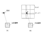
ここで交点qiにあっては、この(10)式の関係式で求められる複数の直線の交点であり、これにより交点検出部3は、図4に示すように、注目画素を中心にした一定範囲で検出されるエッジ方向viを用いて、次式の演算処理を実行することにより、これら一定範囲の各画素による(10)式の関係式を連立方程式により解き、交点qを検出する。これらにより交点検出部3は、勾配解析部2により検出されるエッジ方向v2に基づいて、出力画像データS3の各画素毎に、エッジ方向v2の直線と周辺画素のエッジ方向v2の直線との間で交点qを検出する。
Here, the intersection point q i is an intersection point of a plurality of straight lines obtained by the relational expression (10), whereby the intersection
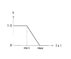
なおここでエッジ方向v2の画素値の勾配の分散を示す固有値λ1が小さい場合、エッジの信頼度が低いと言える。これにより固有値λ1が小さい注目画素、周辺画素で検出されるエッジ方向v2については、(11)式の演算処理に使用しないようにしてもよい。またこの一定範囲で検出されるエッジ方向が平行に近い場合、交点qにあっては、注目画素から遠く離れた位置で検出される。ここでこの実施例では、交点qまでの距離|q|を基準にして画素値を設定して丸まった角を尖らせることにより、あまりに距離が大きくなると、誤って画素値を設定する恐れがある。これにより図5に示すように、注目画素から交点までの距離|q|が一定値nmin以下の場合、値1であって、距離|q|が大きくなるに従って徐々に値が低下して値0となるパラメータkを設定し、このパラメータkを用いて、次式の演算処理を実行することにより、注目画素に近づくように交点qの位置を補正するようにしてもよい。 Here, when the eigenvalue λ1 indicating the dispersion of the gradient of the pixel value in the edge direction v2 is small, it can be said that the reliability of the edge is low. As a result, the edge direction v2 detected by the target pixel and the surrounding pixels having a small eigenvalue λ1 may not be used in the calculation process of the equation (11). When the edge direction detected in this fixed range is nearly parallel, the intersection q is detected at a position far from the target pixel. Here, in this embodiment, if the pixel value is set on the basis of the distance | q | to the intersection q and the rounded corner is sharpened, the pixel value may be set erroneously if the distance becomes too large. . As a result, as shown in FIG. 5, when the distance | q | from the target pixel to the intersection is equal to or less than a certain value nmin, the value is 1, and the value gradually decreases as the distance | q | May be set, and the position of the intersection point q may be corrected so as to be closer to the target pixel by executing the calculation processing of the following equation using the parameter k.
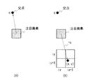
角改善部4は、交点検出部3で検出される交点位置に基づいて、入力画像データS1による画素値を補正して交点の側に角を尖らせる。ここで角改善部4は、図6に示すように、注目画素から交点方向とは逆方向の、注目画素から交点までの距離だけ離れたサンプリング点の画素値を注目画素の画素値に割り当てる。またこのとき、このサンプリング点が、入力画像データS1のサンプリング点と一致しない場合、例えば次式の演算処理により、周囲の画素より対応するサンプリング点の画素値を求め、この画素値を注目画素の画素値fに設定する。なおここでtx及びtyは、この交点までの距離だけ離れたサンプリング点が、それぞれ入力画像データS1の隣接するサンプリング点を、x方向及びy方向に内分する内分比である。これによりこの(13)式の例では直線補間によりこの交点までの距離だけ離れたサンプリング点の画素値fを求めることになるが、この演算処理にあっては、種々の補間演算処理を広く適用することができる。
The
またこのようにして求めた画素値により、入力画像データS1の画素値を変更して画像データS3を出力する。これにより角改善部4は、交点に向かって角が尖るように画素値を補正する。
Further, the pixel value of the input image data S1 is changed according to the pixel value thus obtained, and the image data S3 is output. Thereby, the
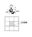
交点信頼度計算部5は、交点検出部3で検出される交点qの信頼度を計算することにより、角改善部4で設定された画素値の信頼度を検出する。すなわち交点検出部3で検出される交点qにあっては、ノイズにより正確に求められない場合等があり、これにより図7に示すように、ばらつきが発生する。ここでこのようなばらつきが大きい場合、この交点にあっては、角である可能性が低いと考えられる。これにより交点信頼度計算部5は、周辺画素で検出される交点との比較により、注目画素で検出される交点の信頼度を計算し、これによりばらつきに応じて値が小さくなるように、信頼度を示すパラメータrを設定する。
The intersection
すなわち交点信頼度計算部5は、注目画素により検出される交点qと、この注目画素を中心とした一定範囲の周辺画素から検出される交点qとの座標値を用いてx方向及びy方向の標準偏差sdvx、sdvyを求め、これらx方向及びy方向の標準偏差sdvx、sdvyより次式の演算処理を実行して標準偏差sdvを計算する。
That is, the intersection
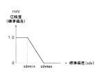
さらにこの標準偏差sdvを用いて、図8に示すように、注目画素より検出される交点についての信頼度を示す信頼度のパラメータrsdvを、標準偏差sdvの増大により値が小さくなるように設定する。なおこの図8に示す例では、標準偏差sdvが一定の範囲sdvmin〜sdvmaxで、標準偏差sdvに比例して値が減少し、この一定の範囲sdvmin〜sdvmax以下及び以上でそれぞれ値1.0及び値0となるように、信頼度のパラメータrsdvを設定する。これにより交点信頼度計算部5は、注目画素における交点と周辺画素による交点とによる分散の大きさにより、注目画素で検出される交点の信頼度を計算する。
Further, using this standard deviation sdv, as shown in FIG. 8, a reliability parameter r sdv indicating the reliability of the intersection detected from the target pixel is set so that the value decreases as the standard deviation sdv increases. To do. In the example shown in FIG. 8, the standard deviation sdv is in a certain range sdvmin to sdvmax, and the value decreases in proportion to the standard deviation sdv. The reliability parameter r sdv is set so that the value becomes zero. Thereby, the intersection
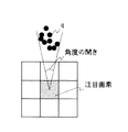
またこのようにして検出される標準偏差sdvの値が同一の場合でも、注目画素と交点との間の距離が近い場合には、この距離が長い場合に比して、信頼性が低いと言える。これにより交点信頼度計算部5は、図9に示すように、注目画素により検出される交点qと、この注目画素を中心とした一定範囲の周辺画素から検出される交点qとの座標値を用いて、注目画素から見たこれら交点の分布する角度を計算する。
Even if the standard deviation sdv value detected in this way is the same, if the distance between the pixel of interest and the intersection is short, it can be said that the reliability is lower than when the distance is long. . Thereby, as shown in FIG. 9, the intersection
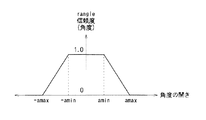
また図10に示すように、注目画素より検出される交点についての信頼度を示す信頼度のパラメータrangleを、この角度の開きが大きくなるに従って値が小さくなるように設定する。なおこの図10に示す例では、角度の開きが正側及び負側の一定の範囲amin〜amax、−amin〜−amaxで角度の開きが大きくなるに従って値が減少し、角度の開きがこの範囲より小さい場合及び大きい場合に、それぞれ値1.0及び値0により信頼度のパラメータrangleを設定する。 As shown in FIG. 10, the reliability parameter r angle indicating the reliability of the intersection detected from the target pixel is set so that the value decreases as the opening of the angle increases. In the example shown in FIG. 10, the value decreases as the angle opening increases in a certain range of amin to amax and −amin to −amax on the positive side and the negative side, and the opening of the angle is within this range. When smaller and larger, the reliability parameter r angle is set with a value of 1.0 and a value of 0, respectively.
交点信頼度計算部5は、次式により示すように、このようにして計算した2種類のパラメータrsdv、rangleを乗算して、最終的にこの注目画素より角改善部4で求められる画素値について、信頼度を示す信頼度のパラメータrを計算する。
The intersection
なおこのようにして検出される信頼度のパラメータrにより、次式により示すように、角改善部4で画素値の設定に供する画素がより近づくように、計算に供するベクトルqを補正し、これにより(12)式について上述したと同様に誤った画素値の設定を防止するようにしてもよい。
It should be noted that the vector q used in the calculation is corrected by the reliability parameter r detected in this way so that the pixel used for setting the pixel value in the
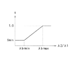
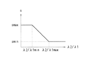
角領域検出部6は、入力画像データS1より角の部分を検出する。ここでエッジ勾配方向v1及びエッジ方向v2についてそれぞれ画素値の勾配の分散を示す固有値λ1、λ2について、この固有値λ1、λ2の比率λ2/λ1が大きい場合には、この注目画素においては、エッジ勾配方向v1の画素値の勾配が急峻であり、エッジである確率が高いと判断することができる。これによりこの場合、エッジ方向v2により検出される交点にあっては、角である確率が高いと言うことができる。
The corner
これにより角領域検出部6は、図11に示すように、この比率λ2/λ1が一定の範囲λ2/λ1min〜λ2/λ1maxにおいては、比率λ2/λ1の値が増大するに従ってほぼ直線的に値が増加し、比率λ2/λ1の値がこの一定の範囲λ2/λ1min、λ2/λ1max以外の場合には、それぞれ最小値Smin及び最大値1.0となるパラメータsを生成する。
As a result, as shown in FIG. 11, the corner
ブレンド比決定部7は、角改善部4による処理結果による画素値と、元の入力画像データS1の画素値とをブレンドするブレンド比を決定する。
The blend
すなわちブレンド比決定部7は、交点信頼度計算部5で検出される信頼度のパラメータrから、図12に示すように、信頼度が高い程、値が大きくなるように、ブレンド比計算用のパラメータtを求める。ここで図12の例では、一定の範囲rmin〜rmaxでは信頼度のパラメータrの値に比例して値が増大し、この範囲rmin〜rmax以外ではそれぞれ最小値及び最大値1.0となるようにパラメータtを設定する。
That is, the blend
また次式により示すように、このようにして求めたパラメータtと、角領域検出部6で求められるパラメータsとを乗算してブレンド比αを計算する。
Also, as shown by the following equation, the blend ratio α is calculated by multiplying the parameter t thus obtained by the parameter s obtained by the corner
ブレンド部8は、次式により示すように、このブレンド比決定部7で求めたブレンド比αにより角改善部4の処理結果S2による画素値と、元の入力画像データS1の画素値とを重み付け加算し、これにより出力画像データS3を生成して出力する。これによりブレンド部8は、ブレンド比決定部7により、エッジ方向v2に係る画素値の勾配の分散λ2とエッジ勾配方向v1に係る画素値の勾配の分散λ1との比率に応じて、交点信頼度計算部5で計算される信頼度を補正して重み付け係数αを求め、この重み付け係数により、入力画像データS1による画素値と角改善部4による画素値とを重み付け加算して出力画像データS3を出力する。
As shown by the following equation, the
(2)実施例の動作
以上の構成において、この画像処理装置1において(図1)、入力画像データS1は、勾配解析部2に入力され、ここで各画素毎に、画素値の勾配が最も大きなエッジ勾配方向v1と、このエッジ勾配方向v1と直交するエッジ方向v2とが順次検出される((1)〜(8)式、図3及び図4)。また入力画像データS1は、交点検出部3において、出力画像データS3の各画素毎に、エッジ方向v2の直線と、周辺画素のエッジ方向v2の直線とで交点が検出され(図4、(9)〜(11)式)、これにより角の頂点が検出される。入力画像データS1は、このようにして検出される交点に基づいて、画素値が補正され、これにより交点に向かって角が尖るように画素値が補正される。
(2) Operation of Embodiment In the above configuration, in the image processing apparatus 1 (FIG. 1), the input image data S1 is input to the
より具体的に、この画像処理装置1では、注目画素から対応する交点の方向とは逆方向であって、注目画素から交点の距離だけ離れたサンプリング点の画素値が、注目画素に設定され(図6、(13)式)、これにより入力画像データS1による画素値が補正される。
More specifically, in the
しかしながらこのようにして検出される交点にあっては、必ずしも正しく角の頂点を検出しているとは限らず、誤検出されている場合もある。 However, at the intersections detected in this way, the corner vertices are not necessarily detected correctly, and may be erroneously detected.
これにより入力画像データS1は、交点検出結果が交点信頼度計算部5に入力され、ここで注目画素による交点と周辺画素による交点との比較により、交点の信頼度が計算される。すなわちこれら注目画素と周辺画素とで交点のばらつきが大きい場合、信頼度が低いと判断することができ、これによりこれら交点の分散の大きさにより、ばらつきが大きい程、値が小さくなるように信頼度のパラメータrsdvが求められる(図7及び図8、(14)式)。
As a result, the intersection detection result of the input image data S1 is input to the intersection
またこのような交点に近づくに従ってこのようなばらつきは小さくなることにより、注目画素より見た、注目画素における交点と周辺画素により検出される交点との分布の角度により、この角度が小さい程、値が小さくなるように信頼度のパラメータrangleが求められる(図9及び図10)。 In addition, since such variation becomes smaller as approaching such an intersection, the smaller the angle, the smaller the value of the distribution of the intersection between the intersection of the pixel of interest and the intersection detected by the surrounding pixels as seen from the pixel of interest. The reliability parameter r angle is determined so that becomes smaller (FIGS. 9 and 10).
またこれらパラメータrsdv及びrangleの乗算により最終的に信頼度のパラメータrが求められる((15)式)。 The reliability parameter r is finally obtained by multiplying these parameters r sdv and r angle (Equation (15)).
またこのような交点の検出基準であるエッジ方向を誤検出している場合等もあることにより、角領域検出部6において、エッジ勾配方向v1及びエッジ方向v2における画素値の勾配の分散を示す固有値λ1、λ2について、この固有値λ1、λ2の比率λ2/λ1により、角である確率が大きい程、値が大きくなるパラメータtが計算され、ブレンド比決定部7において、信頼度のパラメータrとの乗算により、信頼度のパラメータrがパラメータtにより補正されてブレンド比αが計算される。
In addition, since the edge direction that is the detection criterion of such an intersection may be erroneously detected, the corner
入力画像データS1は、角改善部4による処理結果S2との間で、このブレンド比αを用いて重み付け加算処理され、これにより角改善部による処理結果により画素値が補正される。これにより入力画像データS1は、エッジ方向を誤って検出した場合、角の頂点で無い箇所で交点を検出した場合等にあっても、これらの誤検出による誤った角改善部による処理を防止することができ、その分、違和感無く角を尖らせて、画質を向上することができる。
The input image data S1 is subjected to a weighted addition process using the blend ratio α between the input image data S1 and the processing result S2 by the
(3)実施例の効果
以上の構成によれば、画素値の勾配が最も大きなエッジ勾配方向に直交するエッジ方向を検出し、このエッジ方向の交点に基づいて画素値を補正することにより、丸まった角を尖らせることができる。
(3) Advantages of the embodiment According to the above configuration, the edge direction orthogonal to the edge gradient direction with the largest pixel value gradient is detected, and the pixel value is corrected based on the intersection of the edge directions, thereby rounding off. The sharp corner can be sharpened.
またこのとき角改善部において、注目画素から対応する交点の方向とは逆方向であって、注目画素から交点の距離だけ離れたサンプリング点の画素値を、注目画素に設定し、これにより入力画像データによる画素値を補正して角を尖らせることにより、簡易かつ確実に角を尖らせることができる。 At this time, in the angle improvement unit, the pixel value of the sampling point that is opposite to the direction of the corresponding intersection from the target pixel and is separated from the target pixel by the distance of the intersection is set as the target pixel. By correcting pixel values based on data and sharpening the corners, the corners can be sharpened easily and reliably.
また交点信頼度計算部5で計算した信頼度により、入力画像データによる画素値を角改善部による画素値により補正して出力画像データを出力するようにして、この交点信頼度計算部において、注目画素における交点と、周辺画素により検出される交点との比較により、注目画素で検出される交点の信頼度を計算することにより、簡易かつ確実に交点の信頼度を各画素毎に検出することができ、これにより簡易かつ確実に角を尖らせることができる。
Further, the intersection
また具体的に、注目画素における交点と、周辺画素で検出される交点とによる分散の大きさにより、注目画素で検出される交点の信頼度を計算することにより、簡易かつ確実に信頼度を計算することができる。 Specifically, the reliability can be calculated easily and reliably by calculating the reliability of the intersection detected at the pixel of interest by the magnitude of the variance between the intersection at the pixel of interest and the intersection detected at the surrounding pixels. can do.
また注目画素より見た、注目画素における交点と周辺画素で検出される交点との分布の角度により、注目画素で検出される交点の信頼度を計算することにより、交点までの距離を加味して信頼度を求めることができる。 In addition, by calculating the reliability of the intersection detected at the pixel of interest from the distribution angle between the intersection at the pixel of interest and the intersection detected at the surrounding pixels as seen from the pixel of interest, the distance to the intersection is taken into account. Reliability can be obtained.
またエッジ方向に係る画素値の勾配の分散とエッジ勾配方向に係る画素値の勾配の分散との比率に応じて、信頼度を補正して重み付け係数を求め、この重み付け係数により、入力画像データによる画素値と角改善部による画素値とを重み付け加算することにより、エッジ方向を誤って検出した場合、角の頂点で無い箇所で交点を検出した場合等にあっても、これらの誤検出による誤った角改善部による処理を防止することができ、その分、違和感無く角を尖らせて、画質を向上することができる。 Further, the weighting coefficient is obtained by correcting the reliability according to the ratio of the variance of the gradient of the pixel value related to the edge direction and the variance of the gradient of the pixel value related to the edge gradient direction. Even if the edge direction is detected incorrectly by weighted addition of the pixel value and the pixel value from the corner improvement unit, or when an intersection is detected at a location that is not a vertex of the corner, errors due to these erroneous detections Therefore, it is possible to prevent the processing by the corner improving unit, and to sharpen the corner without any discomfort, thereby improving the image quality.
この実施例に係る画像処理装置は、図6との対比により図13に示すように、角改善部において、注目画素の画素値を交点の画素値に設定することにより、角を尖らせる。なおこの実施例に係る画像処理装置は、この角改善部に係る構成、この角改善の処理に関連する構成が異なる点を除いて、実施例1について上述した画像処理装置1と同一に構成され、これにより以下の説明においては、適宜、図1を流用して説明する。
As shown in FIG. 13 in comparison with FIG. 6, the image processing apparatus according to this embodiment sharpens the corner by setting the pixel value of the target pixel to the pixel value of the intersection in the corner improvement unit. The image processing apparatus according to this embodiment is configured in the same manner as the
すなわち角改善部4は、この場合、対応する交点が入力画像データS1のサンプリング点に一致しない場合があることにより、例えば次式により示すように重み付けして、交点に係る入力画像データS1の周辺サンプリング点の画素値を設定する。なおこの(19)式は、ガウシアン型の重み付けであるが、この画素値の設定は、単に距離を変数に設定した一定範囲における外挿処理により求める場合等、種々の手法を広く適用することができる。
That is, in this case, since the corresponding intersection may not coincide with the sampling point of the input image data S1, the
またこれにより交点信頼度計算部5、ブレンド比決定部7は、実施例1について上述した画像処理装置1における場合と同様の処理により、注目画素について信頼度r、重み付け係数αを計算し、この計算結果を角改善部4における処理に対応するように、交点側のサンプリング点に設定した画素値に係る信頼度、重み付け係数に置き換えて出力する。
Thereby, the intersection
またこのように注目画素の画素値を交点の画素値に設定する場合、1つの角に係る交点が複数の注目画素で検出され、これら複数の注目画素からこの1つの角に係るサンプリング点に複数の画素値が求められる場合があることにより、角改善部4は、このような場合、この1つの角について求められる複数の画素値を統計的に処理して、交点の画素値を設定する。なおこの統計的な処理にあっては、複数の画素値を平均値化する場合、さらには信頼度により重み付け加算する場合等、必要に応じて種々の処理を広く適用することができる。
Further, when the pixel value of the target pixel is set to the pixel value of the intersection point in this way, an intersection point related to one corner is detected by a plurality of target pixels, and a plurality of sampling points corresponding to the one corner are detected from the plurality of target pixels. In such a case, the
また交点信頼度計算部5、ブレンド比決定部7は、このような角改善部4における統計的な処理に対応する処理により、複数の注目画素より検出される信頼度、比率λ2/λ1を処理して、重み付け係数αを計算する。
Further, the intersection
この実施例によれば、注目画素の画素値により交点に係るサンプリング点の画素値を設定して角を尖らせるようにしても、実施例1と同様の効果を得ることができる。またこの場合、実施例1の場合に比して、より角を尖らせることができる。 According to this embodiment, even if the pixel value of the sampling point related to the intersection is set by the pixel value of the target pixel and the corner is sharpened, the same effect as that of the first embodiment can be obtained. In this case, the corners can be sharpened as compared with the case of the first embodiment.
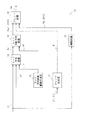
図14は、図1との対比により本発明の実施例3に係る画像処理装置を示す機能ブロック図である。この画像処理装置11において、実施例1について上述した画像処理装置1と同一の構成は、対応する符号を付して示し、重複した説明は省略する。この画像処理装置11においても、演算処理手段である例えばディジタルシグナルプロセッサにより形成される。
FIG. 14 is a functional block diagram illustrating an image processing apparatus according to the third embodiment of the present invention in comparison with FIG. In this
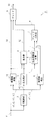
ここでこの画像処理装置11は、解像度変換部12により入力画像データS1の解像度を増大させて画像データS4を生成し、入力画像データS1に代えて、この画像データS4を角改善部4、ブレンド部8に入力する。ここで解像度変換部12は、エッジ勾配方向v1、エッジ方向に輪郭強調処理、平滑化処理して画像データS4を出力する。
Here, the
すなわち図15は、この解像度変換部12を示す機能ブロック図であり、補間処理部13は、例えば線型補間処理、バイキュービック変換処理により、入力画像データS1の解像度を、出力画像データS3の解像度に変換して出力画像データS11により出力する。これによりこの画像データS11は、高周波成分が失われてシャープさの欠けたぼけた画像となる。
That is, FIG. 15 is a functional block diagram showing the
エッジ方向処理部14は、勾配解析部2で検出される入力画像データS1の注目画素に係るエッジ方向v2に基づいて、解像度変換後の画像データS4に係る各画素のエッジ方向vcを計算し、このエッジ方向vcに基づく内挿処理により出力画像データS3の各画素に対応する画素値を順次計算する。
The edge
すなわちエッジ方向処理部14は、図16に示すように、計算対象である画像データS4の注目画素Pcに隣接してなる入力画像データS1の各画素(この図16の例ではP3、P4、P9、P10)について、次式の演算処理を実行することにより、入力画像データS1に係るこれら隣接する画素のエッジ方向v2(v3 、v4 、v9 、v10)を用いた内挿処理により注目画素Pcのエッジ方向vcを計算する。
That is, as shown in FIG. 16, the edge
なおここで、tx 、ty は、それぞれ画像データS1によるサンプリング点P3、P4、P9、P10をx方向及びy方向に内分する注目画素の座標値であり、0≦tx ≦1、0≦ty ≦1である。 Here, t x and t y are the coordinate values of the pixel of interest that internally divides the sampling points P3, P4, P9, and P10 by the image data S1 in the x and y directions, respectively, 0 ≦ t x ≦ 1, 0 ≦ t y ≦ 1.
さらにエッジ方向処理部14は、このようにして計算される注目画素Pcのエッジ方向vcより、注目画素Pcのサンプリング点からエッジ方向vcの直線上に、入力画像データS1のサンプリングピッチによるサンプリング点P−2、P−1、P1、P2を所定個数だけ設定する。さらにこのサンプリング点P−2、P−1、P1、P2と注目画素Pcとについて、入力画像データS1の画素値を用いた補間演算処理によりそれぞれ画素値を計算し、これにより勾配解析部2の検出結果に基づいて、出力画像データS3の各画素毎に、エッジ方向vcに延長する直線上に、入力画像データS1の内挿処理によるエッジ方向の内挿画像データを生成する。これによりエッジ方向処理部14は、入力画像データS1をエッジ方向に平滑化しながら解像度を変換する。
Further, the edge
またこのとき後述するエッジ方向範囲の決定部15による計算結果に従って、このようにして設定するサンプリング点の数を切り換え、また続くフィルタリングの処理を切り換え、これにより注目画素のエッジ方向vcに係るエッジの信頼度に応じてフィルタリング処理のタップ数を切り換える。具体的に、例えば続くフィルタリングの処理を3タップのフィルタリングにより実行する場合、注目画素Pcについては、周辺画素P3、P4、P9、P10を用いた線型補間により画素値を計算し、また同様にして前後のサンプリング点P−1、P1については、それぞれP2、P3、P8、P9及びP4、P5、P10、P11を用いた線型補間により画素値を計算する。これに対して例えば続くフィルタリングの処理を5タップのフィルタリングにより実行する場合、注目画素Pcについては、周辺画素P3、P4、P9、P10を用いた線型補間により画素値を計算し、また同様にしてサンプリング点P−2、P−1、P1、P2について、画素値を計算する。
At this time, the number of sampling points set in this way is switched in accordance with the calculation result by the edge direction
続いてエッジ方向処理部14は、このようにして計算したサンプリング点P−2、P−1、P1、P2及び注目画素Pcの画素値をフィルタリング処理により平滑化処理し、注目画素Pcの画素値Pc’を決定する。すなわち3タップのフィルタリングによる場合には、例えば次式の演算処理により注目画素Pcの画素値Pc’を計算する。
Subsequently, the edge
これに対して5タップのフィルタリングによる場合には、例えば次式の演算処理により注目画素Pcの画素値Pc’を計算する。 On the other hand, in the case of 5-tap filtering, for example, the pixel value Pc ′ of the target pixel Pc is calculated by the following arithmetic processing.
これらによりこの実施例においては、エッジ方向の内挿画像データの平滑化処理により、出力画像データS3の画素に対応する画素値を計算し、これにより高周波成分の喪失を有効に回避しつつ、エッジにおけるジャギーの発生を防止するようになされている。なおこれら内挿画像データの生成に供する補間演算処理にあっては、隣接する近傍画素の画素値を用いた線型補間に限らず、種々の周辺画素を用いた種々の補間演算処理方法を広く適用することができる。またこの内挿画像データを用いたフィルタリング処理に係る演算処理についても、(21)式、(22)式について上述した演算処理に限らず、種々の重み付け係数による補間演算処理を広く適用することができる。 Accordingly, in this embodiment, the pixel value corresponding to the pixel of the output image data S3 is calculated by the smoothing process of the interpolated image data in the edge direction, thereby effectively avoiding the loss of the high frequency component, and the edge It is designed to prevent the occurrence of jaggies. In addition, in the interpolation calculation processing used to generate these interpolated image data, not only linear interpolation using pixel values of adjacent neighboring pixels, but also various interpolation calculation processing methods using various peripheral pixels are widely applied. can do. In addition, the arithmetic processing related to the filtering processing using the interpolated image data is not limited to the arithmetic processing described above with respect to the equations (21) and (22), and the interpolation arithmetic processing using various weighting coefficients can be widely applied. it can.
ところでこのように画素毎にエッジ方向を検出して画像データS3に係る画素値を計算する場合、エッジでは無い箇所で輝度勾配と直交する方向に平滑化処理する恐れもある。このような場合に、大きな範囲である多くのタップ数によりフィルタリング処理したのでは、却って画質を劣化することになる。しかしながらこれとは逆に、エッジの部分では、大きな範囲でフィルタリング処理して、一段と確実にジャギーの発生を防止して滑らかなエッジを形成することができる。 By the way, when the edge direction is detected for each pixel and the pixel value related to the image data S3 is calculated in this way, there is a possibility that the smoothing process may be performed in a direction orthogonal to the luminance gradient at a location that is not an edge. In such a case, if the filtering process is performed with a large number of taps in a large range, the image quality is deteriorated. However, on the contrary, the edge portion can be filtered in a large range to further prevent jaggies and form a smooth edge.
これによりこの実施例では、画素毎にフィルタリング処理するタップ数を切り換え、これにより画素毎にエッジ方向に平滑化処理する範囲を可変する。またこのような平滑化処理する範囲をエッジ方向vcへのエッジの信頼度により可変し、これにより平滑化処理による画質劣化を防止する。 Thus, in this embodiment, the number of taps for filtering processing is switched for each pixel, and thereby the range for smoothing processing in the edge direction is varied for each pixel. Further, such a smoothing range is varied depending on the reliability of the edge in the edge direction vc, thereby preventing image quality deterioration due to the smoothing process.
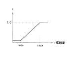
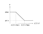
具体的に、この実施例では、エッジ方向v2の固有値λ2と、エッジ勾配方向v1の固有値λ1との比率λ2/λ1により、このようなエッジ方向vcへのエッジの信頼度を検出する。すなわちこの比率λ2/λ1が小さい場合には、この注目画素においては、エッジ勾配方向v1の画素値の勾配が支配的であり、エッジ方向v2に強いエッジであると判断することができる。これによりエッジ方向処理範囲の決定部15は、図17に示すように、この比率λ2/λ1が一定の範囲λ2/λ1min〜λ2/λ1maxにおいては、比率λ2/λ1の値が低下するに従ってほぼ直線的に値が増加し、比率λ2/λ1の値がこの一定の範囲λ2/λ1min〜λ2/λ1max以外の場合には、それぞれ最大値pmax及び最小値pminとなるパラメータpを生成する。これによりエッジ方向へのエッジの信頼度に応じて値の変化するパラメータpを生成する。
Specifically, in this embodiment, the reliability of the edge in the edge direction vc is detected based on the ratio λ2 / λ1 between the eigenvalue λ2 in the edge direction v2 and the eigenvalue λ1 in the edge gradient direction v1. That is, when the ratio λ2 / λ1 is small, it can be determined that the pixel value gradient in the edge gradient direction v1 is dominant and the edge is a strong edge in the edge direction v2. As a result, the edge direction processing
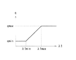
またエッジ勾配方向v1の固有値λ1が大きい場合、エッジを挟んでコントラストが大きい場合であり、はっきりとしたエッジであると言える。これによりエッジ方向処理範囲の決定部15は、図18に示すように、所定の範囲λ1min〜λ1maxで、固有値λ1に応じてほぼ直線的に値が増加し、これらの範囲λ1min〜λ1maxより値の小さい側及び大きい側では、それぞれ下限値qmin、上限値qmaxとなるパラメータqを生成する。これによりエッジの立ち上がりに応じて値の変化するパラメータqを生成する。
Further, when the eigenvalue λ1 in the edge gradient direction v1 is large, the contrast is large across the edge, and it can be said that the edge is clear. As a result, as shown in FIG. 18, the edge direction processing
エッジ方向処理範囲の決定部15は、これら2つのパラメータp及びqについて、次式により表される乗算処理を実行し、これによりエッジ方向処理に係るフィルタリング処理の範囲rを計算する。
The edge direction processing
なおエッジ方向処理範囲の決定部15においては、エッジ方向処理部14の処理に係る画像データS4のサンプリング点に対応するように、入力画像データS1のサンプリング点による固有値λ1、λ2を画像データS4のサンプリング点に係る固有値に変換してフィルタリング処理の範囲rを計算する。この場合に、入力画像データS1のサンプリング点によりフィルタリング処理の範囲rを計算した後、この計算結果の内挿処理により画像データS3のサンプリング点に係るフィルタリング処理の範囲rを計算するようにしてもよく、またこれとは逆に、入力画像データS1のサンプリング点に係る固有値λ1、λ2を内挿処理して画像データS4のサンプリング点に係る固有値λ1、λ2を計算した後、この計算結果から画像データS4のサンプリング点に係るフィルタリング処理の範囲rを計算するようにしてもよい。
Note that the edge direction processing
しかしてエッジ方向処理部14は、このようにして計算される範囲rによりフィルタリング処理のタップ数を切り換えて画像データS3に係る注目画素Pcの画素値Pc’を計算する。
Accordingly, the edge
このフィルタリングの処理において、エッジ方向処理部14は、フィルタリング結果の融合処理を実行することにより、実数値のタップ数によりフィルタリング処理を実行し、これにより整数値のタップ数によりフィルタリング処理した場合の、タップ数の切り換え時における不自然さを解消する。
In this filtering process, the edge
すなわちエッジ方向処理部14では、次式により示される整数値によるタップ数のフィルタが定義される。なおここでこの実施例において、この整数値のタップ数は、1、3、5、……による奇数値が適用される。
That is, the edge
ここでfloor(n)は、nを越えない最大の整数のタップ数であり、ceil(n)は、n以上の最小の整数のタップ数である。またnrealは、(12)式により計算された範囲rが適用される。これによりn=3.5の場合、floor(n)はタップ数3であり、ceil(n)はタップ数5となる。 Here, floor (n) is the maximum integer tap number not exceeding n, and ceil (n) is the minimum integer tap number equal to or greater than n. The range r calculated by the equation (12) is applied to nreal. Thus, when n = 3.5, floor (n) has 3 taps and ceil (n) has 5 taps.
フィルタリング結果の融合処理は、これら2種類のフィルタリング処理結果を用いて次式の演算処理を実行することにより、実数値によるフィルタリング処理結果f(n)を計算して実行される。これによりエッジ方向処理部14は、フィルタリング処理の範囲rによりこれら2種類のタップ数によるフィルタリング処理を実行し、さらにこれら2種類のフィルタリング処理結果を用いて(25)式の演算処理を実行することにより、画像データS3に係る注目画素Pcの画素値Pc’を計算する。これによりエッジ方向処理部14は、エッジ方向へのエッジの信頼度に応じたタップ数によりフィルタリング処理して画像データS3に係る注目画素Pcの画素値Pc’を計算するようにして、このタップ数を少数点以下の単位で可変する。
The filtering result fusion processing is executed by calculating the real-value filtering processing result f (n) by executing the following arithmetic processing using these two types of filtering processing results. Thereby, the edge
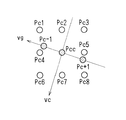
エッジ勾配方向処理部16は、このようにしてエッジ方向処理部14で計算される画像データS4に係る注目画素Pcの画素値Pc’を用いて、エッジ勾配方向v1に輪郭強調処理を実行する。すなわちエッジ勾配方向処理部16は、図19に示すように、エッジ方向処理部14において、画像データS4に係る注目画素Pcでエッジ方向vcを計算したと同様にして、入力画像データS1に係る隣接するサンプリング点のエッジ勾配方向v1より、画像データS4に係る注目画素Pccのエッジ勾配方向vgを計算する。
The edge gradient
さらにエッジ勾配方向処理部16は、このようにして計算される注目画素Pccのエッジ勾配方向vgより、注目画素Pccのサンプリング点からエッジ勾配方向vgの直線上に、画像データS4のサンプリングピッチによるサンプリング点Pc−1、Pc+1を所定個数だけ設定する。さらにこのサンプリング点Pc−1、Pc+1と注目画素Pccとについて、エッジ方向処理部14から出力される画素値を用いた補間演算処理によりそれぞれ画素値を計算する。これによりエッジ方向処理部14は、勾配解析部2の検出結果に基づいて、画像データS4の各画素毎に、エッジ勾配方向vgに延長する直線上に、エッジ方向処理部14から出力される画素値による画像データの内挿処理によるエッジ勾配方向の内挿画像データを生成する。
Further, the edge gradient
続いてエッジ方向処理部14は、このようにして計算したサンプリング点Pc−1、Pc+1と注目画素Pccの画素値をフィルタリング処理し、注目画素Pccの画素値Pcc’を決定する。しかしてこの図19の例にあっては、3タップにより注目画素Pccの画素値Pcc’を計算する場合であり、サンプリング点Pc−1の画素値にあっては、周辺のサンプリング点Pc1、Pc2、Pc4、Pccによる線型補間により生成され、またサンプリング点Pc+1の画素値にあっては、周辺のサンプリング点Pcc、Pc5、Pc7、Pc8による線型補間により生成されるようになされている。これによりエッジ勾配方向処理部16は、エッジを横切る方向に輪郭強調するようになされている。なおこれら内挿画像データの生成に供する補間演算処理にあっては、このような隣接する近傍画素の画素値を用いた線型補間に限らず、種々の周辺画素を用いた補間演算処理方法を広く適用することができる。またこの内挿画像データを用いたフィルタリング処理に係る演算処理についても、種々の重み付け係数による補間演算処理を広く適用することができる。
Subsequently, the edge
ブレンド比決定部17は、エッジ方向vcへのエッジの信頼度に応じてブレンド用の重み付け係数を生成する。すなわち上述したようにエッジ方向に平滑化処理し、エッジと直交する方向に輪郭強調する場合にあっては、自然画において、不自然に輪郭強調する場合がある。このためこの実施例においては、別途、補間処理部13で従来手法により生成した画像データS11に係る画素値Paと、エッジ勾配方向処理部16で生成される画素値Pcc’とをブレンド処理部18により重み付け加算して画像データS4を生成し、ブレンド比決定部17は、この重み付け加算処理に係る重み付け係数を可変する。またこの重み付け係数の可変を、エッジ方向へのエッジの信頼度により可変し、これにより過度なエッジに係る処理の不自然さを防止する。またこのエッジ方向へのエッジの信頼度に、エッジ方向v2の固有値λ2と、エッジ勾配方向v1の固有値λ1との比率λ2/λ1を適用して処理する。
The blend
具体的に、この比率λ2/λ1が小さい場合には、この注目画素においては、エッジ勾配方向v1の勾配が支配的であり、エッジ方向v2に強いエッジであると判断することができる。これによりブレンド比決定部17は、図20に示すように、この比率λ2/λ1が一定の範囲λ2/λ1min〜λ2/λ1maxにおいては、比率λ2/λ1の値が低下するに従ってほぼ直線的に値が増加し、比率λ2/λ1の値がこの一定の範囲λ2/λ1min〜λ2/λ1max以外の場合には、それぞれ最大値smax及び最小値sminとなるパラメータsを生成する。これによりエッジ方向へのエッジの信頼度に応じて値の変化するパラメータsを生成する。
Specifically, when the ratio λ2 / λ1 is small, it can be determined that the gradient in the edge gradient direction v1 is dominant in the target pixel and the edge is strong in the edge direction v2. Accordingly, as shown in FIG. 20, the blend
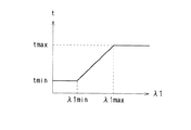
またエッジ勾配方向v1の固有値λ1が大きい場合、エッジを挟んでコントラストが大きい場合であり、はっきりとしたエッジであると言える。これによりブレンド比決定部17は、図21に示すように、所定の範囲λ1min、λ1maxで、固有値λ1に応じてほぼ直線的に値が増加し、これらの範囲λ1min、λ1maxでは、それぞれ下限値tmin、上限値tmaxとなるパラメータtを生成する。これによりエッジの立ち上がりに応じて値の変化するパラメータtを生成する。
Further, when the eigenvalue λ1 in the edge gradient direction v1 is large, the contrast is large across the edge, and it can be said that the edge is clear. Accordingly, as shown in FIG. 21, the blend
ブレンド比決定部17は、次式により示すように、これらパラメータs、tを乗算して、ブレンド用の重み付け係数β(0≦β≦1)を計算する。
The blend
なおブレンド比決定部17は、画像データS11に係るサンプリング点に対応するように、入力画像データS1のサンプリング点による固有値λ1、λ2を画像データS11のサンプリング点に係る固有値に変換してブレンド用の重み付け係数βを計算する。
The blend
ブレンド処理部18は、次式の演算処理を実行することにより、エッジ勾配方向処理部16で計算される画素値Pcc’による画像データS12と、補間処理部13で計算される画素値Paによる画像データS11とをブレンド比決定部17による重み付け係数βにより重み付け加算処理し、その処理結果を画像データS4により出力する。
The
これらにより解像度変換部12は、勾配解析部2で検出されるエッジ勾配方向v1、エッジ方向v2に輪郭強調処理、平滑化処理しながら、入力画像データS1の解像度を変換して画像データS4を出力する。
Thus, the
またこれら解像度変換の処理に対応して、交点検出部3は、入力画像データS1の各画素について求められる交点から、解像度変換後の画像データである出力画像データS3の各画素毎の交点を計算し、この交点を角改善部4、交点信頼度計算部5に通知する。なおこのような交点の計算においては、図22及び次式により示すように、近傍画素で検出される交点qa、qb、qc、qdを用いた補間演算処理を適用することができる。
Corresponding to these resolution conversion processes, the
また角領域検出部6においても、同様にして、入力画像データS1の各画素について求められるパラメータsを、出力画像データS2の各画素に係るパラメータsに変換して出力する。
Similarly, the corner
以上の構成によれば、入力画像データS1の解像度を出力画像データS2の解像度に変換して角改善部により処理することにより、解像度の変換により角がまるくなるような場合であっても、解像度変換前の入力画像データにより求められるエッジ方向により角を尖らせることができ、これにより一段と画質を向上することができる。 According to the above configuration, the resolution of the input image data S1 is converted to the resolution of the output image data S2 and processed by the corner improvement unit, so that even if the corner is rounded by the resolution conversion, the resolution The corners can be sharpened by the edge direction obtained from the input image data before the conversion, thereby further improving the image quality.
ところで上述したようにエッジ方向、エッジ勾配方向を検出して角を尖らせる場合、エッジ方向、エッジ勾配方向の検出に供する特性によっては、エッジを検出できない場合もあり、これにより例えば特定のパターンで角を尖らせることが困難になることが判った。 By the way, when the edge direction and the edge gradient direction are detected and the corner is sharpened as described above, the edge may not be detected depending on the characteristics used for the detection of the edge direction and the edge gradient direction. It turned out to be difficult to sharpen the corners.
このため図23に示すように、この実施例に係る画像処理装置21は、複数の画像処理部21A〜21Eによりそれぞれエッジ方向を検出して角を尖らせ、その処理結果を統合部22により合成して出力画像データS3を出力する。
Therefore, as shown in FIG. 23, the
ここで画像処理部21A〜21Eは、それぞれ図14について上述した画像処理装置の構成が適用される。これにより各画像処理部21Aは、勾配解析部2でエッジ勾配方向v1、エッジ方向v2、固有値λ1、λ2を検出して続く交点検出部3により交点を検出すると共に、解像度変換部12により入力画像データS1の解像度を出力画像データS3の解像度に変換し、この解像度変換部12の出力データについて、角改善部4により角を尖らせ、一連の処理結果による画像データf1〜fnを出力する。
Here, the configuration of the image processing apparatus described above with reference to FIG. 14 is applied to each of the
これら画像処理部21A〜21Eは、勾配解析部2でx方向及びy方向の偏微分gx 及びgy を計算する際の微分演算子の設定により、このような一連の処理基準であるエッジ勾配方向、エッジ方向の検出に供する特性が異なるように設定される。
These
具体的に、これら画像処理部21A〜21Eは、(29)〜(33)式により表される微分演算子により、これらx方向及びy方向の偏微分gx 及びgy をそれぞれ計算する。これによりこの画像処理装置21では、これら複数の画像処理部21A〜21Eにおける微分演算子の位相特性を異ならせて、エッジ方向、エッジ勾配方向の検出に供する特性が異なるように設定され、1つ又は複数の画像処理部でエッジ方向、エッジ勾配方向を正しく検出できない場合、誤り検出した場合等にあっても、何れか1つの画像処理部では、これらを正しく検出できるようになされている。なおこのような微分演算子にあっては、位相特性に代えて、又は位相特性に加えて、周波数特性を異ならせるようにしてもよい。
Specifically, the
またこのような微分演算子による異なる特性の設定に代えて、エッジ勾配方向、エッジ方向に供する範囲を異ならせて、エッジ勾配方向、エッジ方向の検出に供する特性を異ならせるようにしてもよい。またこの場合、勾配行列の生成に供するサンプル数自体を異ならせてこのような範囲を異ならせるようにしてもよく、またダウンサンプリングにより範囲を異ならせるようにしてもよい。 Further, instead of setting different characteristics by such a differential operator, the edge gradient direction and the range provided for the edge direction may be varied to vary the characteristics used for detection of the edge gradient direction and the edge direction. In this case, the range may be made different by changing the number of samples used to generate the gradient matrix, or the range may be made different by downsampling.
統合部22は、次式の演算処理により、これら画像処理部21A〜21Eによる処理結果を平均値化して出力画像データS3を出力する。なおここでこの画像処理部21A〜21Eによる処理結果の合成にあっては、各特性によるエッジ検出結果等の信頼性により重み付け加算するようにしてもよい。
The
この実施例によれば、エッジ方向の検出に供する特性の異なる複数の画像処理部により、それぞれエッジ方向を検出して角を尖らせることにより、違和感無く角を尖らせて、画質を向上するようにして、特定パターンにおける誤った処理を防止することができ、これにより一段と画質を向上することができる。 According to this embodiment, the plurality of image processing units having different characteristics for detecting the edge direction detect the edge direction and sharpen the corner, thereby sharpening the corner without a sense of incongruity and improving the image quality. Thus, it is possible to prevent erroneous processing in a specific pattern, thereby further improving the image quality.
なお上述の実施例3においては、解像度変換部12において、エッジ勾配方向及びエッジ方向にそれぞれ輪郭強調処理、平滑化処理して解像度を変換する場合について述べたが、本発明はこれに限らず、解像度の変換にあっては線型補間処理、バイキュービック変換処理等、種々の手法を広く適用することができる。
In the above-described third embodiment, the
また上述の実施例においては、交点の標準偏差と分布の角度とにより各注目画素による交点の信頼度を計算する場合について述べたが、本発明はこれに限らず、実用上十分な特性を確保することができる場合、これらの何れかにより信頼度を計算するようにしてもよい。 Further, in the above-described embodiment, the case where the reliability of the intersection point by each pixel of interest is calculated based on the standard deviation of the intersection point and the distribution angle has been described. If it is possible, the reliability may be calculated by any of these.
また上述の実施例においては、演算処理手段により所定のプログラムを実行して画像データを処理する場合について述べたが、本発明はこれに限らず、ハードウエアの構成により画像データを処理する場合にも広く適用することができる。 Further, in the above-described embodiment, the case where the processing unit executes the predetermined program to process the image data has been described. However, the present invention is not limited to this, and the case where the image data is processed by the hardware configuration. Can also be widely applied.
本発明は、例えば解像度の変換に適用することができる。 The present invention can be applied to, for example, resolution conversion.
1、11、21……画像処理装置、2……勾配解析部、3……交点検出部、4……角改善部、5……交点信頼度計算部、6……角領域検出部、7……ブレンド比決定部、8……ブレンド部、12……解像度変換部、21A〜21E……画像処理部、22……統合部
1, 11, 21... Image processing device, 2... Gradient analysis unit, 3... Intersection detection unit, 4... Corner improvement unit, 5. ...... Blend ratio determination unit, 8 ... Blend unit, 12 ... Resolution conversion unit, 21A to 21E ... Image processing unit, 22 ... Integration unit
Claims (15)
前記入力画像データの各画素毎に、画素値の勾配が最も大きなエッジ勾配方向と直交するエッジ方向を検出する勾配解析部と、
前記勾配解析部により検出される前記エッジ方向に基づいて、前記出力画像データの各画素毎に、前記エッジ方向の直線と周辺画素の前記エッジ方向の直線との間で交点を検出する交点検出部と、
前記出力画像データの各画素毎に、注目画素から前記交点検出部で検出される対応する前記交点の方向とは逆方向であって、前記注目画素から前記交点の距離だけ離れたサンプリング点の画素値を、前記注目画素の画素値に設定することにより、前記交点の側に角を尖らせる角改善部と、
前記注目画素及び周辺画素で検出される交点のばらつきに応じて、前記注目画素で検出される前記交点の信頼度を計算する信頼度計算部と、
前記信頼度に応じて、前記入力画像データによる画素値と前記角改善部による画素値とを重み付け加算することにより生成される前記出力画像データを出力するブレンド部と
を備えることを特徴とする画像処理装置。 In an image processing apparatus that processes input image data and outputs output image data,
For each pixel of the input image data, a gradient analysis unit that detects an edge direction orthogonal to an edge gradient direction where the gradient of the pixel value is the largest,
An intersection detection unit that detects an intersection between the straight line in the edge direction and the straight line in the edge direction of peripheral pixels for each pixel of the output image data based on the edge direction detected by the gradient analysis unit. When,
For each pixel of the output image data, a pixel at a sampling point that is in a direction opposite to the direction of the corresponding intersection detected by the intersection detection unit from the target pixel and is separated from the target pixel by the distance of the intersection value, by setting the pixel value of the pixel of interest, and the corner correction part that pointed corners on the side of the front Symbol intersection,
A reliability calculation unit that calculates the reliability of the intersection detected at the target pixel according to the variation of the intersection detected at the target pixel and the surrounding pixels ;
An image comprising: a blending unit that outputs the output image data generated by weighting and adding a pixel value based on the input image data and a pixel value based on the corner improvement unit according to the reliability. Processing equipment.
前記注目画素の画素値により前記交点に係るサンプリング点の画素値を設定することにより、前記入力画像データによる画素値をさらに補正する
ことを特徴とする請求項1に記載の画像処理装置。 The angle improving unit is
Wherein by setting the pixel values of the sampling points according to the intersection by the pixel value of the pixel of interest, the image processing apparatus according to claim 1, characterized by further correcting the pixel value by the input image data.
前記注目画素及び前記周辺画素で検出される交点の位置の標準偏差を算出し、算出した前記標準偏差に応じて前記信頼度を計算する
ことを特徴とする請求項1に記載の画像処理装置。 The reliability calculation unit includes:
The image processing apparatus according to claim 1, wherein the target pixel and calculates the standard deviation of the position of an intersection detected by the peripheral pixels, to calculate the signal Yoriyukido in accordance with the calculated the standard deviation .
前記注目画素より見た、前記注目画素及び前記周辺画素で検出される交点の分布の角度を算出し、前記分布の角度にさらに応じて前記信頼度を計算する
ことを特徴とする請求項3に記載の画像処理装置。 The reliability calculation unit includes:
Viewed from the target pixel, according to the attention pixel and calculates the angular distribution of the intersection points detected by the peripheral pixels, and calculates the signal Yoriyukido further depending on the angle of the distribution Item 4. The image processing apparatus according to Item 3 .
前記エッジ方向に係る画素値の勾配の分散と前記エッジ勾配方向に係る画素値の勾配の分散との比率に応じて、前記信頼度を補正して重み付け係数を求め、
前記重み付け係数により、前記入力画像データによる画素値と前記角改善部による画素値とを重み付け加算する
ことを特徴とする請求項1に記載の画像処理装置。 The blend part is
According to the ratio of the variance of the gradient of the pixel value related to the edge direction and the variance of the gradient of the pixel value related to the edge gradient direction, the reliability is corrected to obtain a weighting coefficient,
Wherein the weighting factor, the image processing apparatus according to claim 1, characterized in that you weighted addition of the pixel values by the angle correction part and the pixel value by the input image data.
出力する解像度変換部を有し、
前記交点検出部は、
前記入力画像データの画素毎に、前記交点を検出した後、該検出結果に基づいて前記解像度変換部から出力される各画素の前記交点を検出することにより、前記出力画像データの各画素毎に、前記交点を検出し、
前記角改善部は、
前記解像度変換部から出力される画像データについて、前記交点の側に角を尖らせる
ことを特徴とする請求項1に記載の画像処理装置。 A resolution conversion unit that converts the resolution of the input image data into the resolution of the output image data and outputs the converted image data to the corner improvement unit;
The intersection detection unit
After detecting the intersection point for each pixel of the input image data, detecting the intersection point of each pixel output from the resolution conversion unit based on the detection result, for each pixel of the output image data , Detect the intersection point,
The angle improving unit is
The image processing apparatus according to claim 1, wherein corners of the image data output from the resolution conversion unit are sharpened toward the intersection.
それぞれ前記入力画像データを処理して画像データを出力する複数の画像処理部と、
前記複数の画像処理部から出力される前記画像データを合成して前記出力画像データを生成する統合部とを備え、
前記画像処理部は、
前記入力画像データの各画素毎に、画素値の勾配が最も大きなエッジ勾配方向と直交するエッジ方向を検出する勾配解析部と、
前記勾配解析部により検出される前記エッジ方向に基づいて、前記出力画像データの各画素毎に、前記エッジ方向の直線と周辺画素の前記エッジ方向の直線との間で交点を検出する交点検出部と、
前記入力画像データの解像度を変換して出力データを出力する解像度変換部と、
前記出力画像データの各画素毎に、注目画素から前記交点検出部で検出される対応する前記交点の方向とは逆方向であって、前記注目画素から前記交点の距離だけ離れたサンプリング点の画素値を、前記注目画素の画素値に設定することにより、前記交点の側に角を尖らせる角改善部と、
前記注目画素及び周辺画素で検出される交点のばらつきに応じて、前記注目画素で検出される前記交点の信頼度を計算する信頼度計算部と、
前記信頼度に応じて、前記出力データの画素値と前記角改善部による画素値とを重み付け加算することにより生成される前記画像データを出力するブレンド部とを有し、
前記複数の画像処理部は、
前記エッジ方向の検出に供する特性が異なる特性に設定された
ことを特徴とする画像処理装置。 In an image processing apparatus that processes input image data and outputs output image data,
A plurality of image processing units each processing the input image data and outputting image data;
An integration unit that generates the output image data by combining the image data output from the plurality of image processing units;
The image processing unit
For each pixel of the input image data, a gradient analysis unit that detects an edge direction orthogonal to an edge gradient direction where the gradient of the pixel value is the largest,
An intersection detection unit that detects an intersection between the straight line in the edge direction and the straight line in the edge direction of peripheral pixels for each pixel of the output image data based on the edge direction detected by the gradient analysis unit. When,
A resolution converter that converts the resolution of the input image data and outputs output data;
For each pixel of the output image data, a pixel at a sampling point that is in a direction opposite to the direction of the corresponding intersection detected by the intersection detection unit from the target pixel and is separated from the target pixel by the distance of the intersection value, by setting the pixel value of the pixel of interest, and the corner correction part that pointed corners on the side of the front Symbol intersection,
A reliability calculation unit that calculates the reliability of the intersection detected at the target pixel according to the variation of the intersection detected at the target pixel and the surrounding pixels ;
A blend unit that outputs the image data generated by weighted addition of the pixel value of the output data and the pixel value of the corner improvement unit according to the reliability;
The plurality of image processing units are:
An image processing apparatus, wherein the characteristics used for detecting the edge direction are set to different characteristics.
処理対象の画素を中心とした一定範囲の画素値を微分して、前記エッジ方向を検出し、
前記複数の画像処理部は、
前記エッジ検出部における前記画素値の微分に供する微分演算子が異なるように設定されて、前記エッジ方向の検出に供する特性が異なる特性に設定された
ことを特徴とする請求項7に記載の画像処理装置。 The edge detector
Differentiating a certain range of pixel values around the pixel to be processed to detect the edge direction,
The plurality of image processing units are:
8. The image according to claim 7 , wherein a differential operator used for differentiation of the pixel value in the edge detection unit is set to be different, and characteristics used for detection of the edge direction are set to different characteristics. Processing equipment.
処理対象の画素を中心とした一定範囲の画素値を微分して、前記エッジ方向を検出し、
前記複数の画像処理部は、
前記エッジ検出部における前記一定範囲が異なる範囲に設定されて、前記エッジ方向の検出に供する特性が異なる特性に設定された
ことを特徴とする請求項7に記載の画像処理装置。 The edge detector
Differentiating a certain range of pixel values around the pixel to be processed to detect the edge direction,
The plurality of image processing units are:
The image processing apparatus according to claim 7 , wherein the predetermined range in the edge detection unit is set to a different range, and characteristics used for detection of the edge direction are set to different characteristics.
前記入力画像データの各画素毎に、画素値の勾配が最も大きなエッジ勾配方向と直交するエッジ方向を検出する勾配解析のステップと、
前記勾配解析のステップにより検出される前記エッジ方向に基づいて、前記出力画像データの各画素毎に、前記エッジ方向の直線と周辺画素の前記エッジ方向の直線との間で交点を検出する交点検出のステップと、
前記出力画像データの各画素毎に、注目画素から前記交点検出のステップで検出される対応する前記交点の方向とは逆方向であって、前記注目画素から前記交点の距離だけ離れたサンプリング点の画素値を、前記注目画素の画素値に設定することにより、前記交点の側に角を尖らせる角改善のステップと、
前記注目画素及び周辺画素で検出される交点のばらつきに応じて、前記注目画素で検出される前記交点の信頼度を計算する信頼度計算のステップと、
前記信頼度に応じて、前記入力画像データによる画素値と前記角改善のステップによる画素値とを重み付け加算することにより生成される前記出力画像データを出力するブレンドのステップと
を有することを特徴とする画像処理方法。 In an image processing method for processing input image data and outputting output image data,
For each pixel of the input image data, a gradient analysis step of detecting an edge direction orthogonal to an edge gradient direction with the largest pixel value gradient;
Intersection detection for detecting an intersection between the straight line in the edge direction and the straight line in the edge direction of peripheral pixels for each pixel of the output image data based on the edge direction detected in the gradient analysis step. And the steps
For each pixel of the output image data, a sampling point that is in a direction opposite to the direction of the corresponding intersection detected from the target pixel in the intersection detection step and is separated from the target pixel by the distance of the intersection. the pixel value, by setting the pixel value of the pixel of interest, a step of angular improvement sharpened corners on the side of the front Symbol intersection,
A reliability calculation step of calculating the reliability of the intersection detected at the target pixel according to the variation of the intersection detected at the target pixel and the surrounding pixels ;
A blending step for outputting the output image data generated by weighted addition of the pixel value based on the input image data and the pixel value based on the angle improvement step according to the reliability. Image processing method.
それぞれ前記入力画像データを処理して画像データを出力する複数の画像処理のステップと、
前記複数の画像処理のステップから出力される前記画像データを合成して前記出力画像データを生成する統合のステップとを備え、
前記画像処理のステップは、
前記入力画像データの各画素毎に、画素値の勾配が最も大きなエッジ勾配方向と直交するエッジ方向を検出する勾配解析のステップと、
前記勾配解析のステップにより検出される前記エッジ方向に基づいて、前記出力画像データの各画素毎に、前記エッジ方向の直線と周辺画素の前記エッジ方向の直線との間で交点を検出する交点検出のステップと、
前記入力画像データの解像度を変換して出力データを出力する解像度変換のステップと、
前記出力画像データの各画素毎に、注目画素から前記交点検出のステップで検出される対応する前記交点の方向とは逆方向であって、前記注目画素から前記交点の距離だけ離れたサンプリング点の画素値を、前記注目画素の画素値に設定することにより、前記交点の側に角を尖らせる角改善のステップと、
前記注目画素及び周辺画素で検出される交点のばらつきに応じて、前記注目画素で検出される前記交点の信頼度を計算する信頼度計算のステップと、
前記信頼度に応じて、前記出力データの画素値と前記角改善のステップによる画素値とを重み付け加算することにより生成される前記画像データを出力するブレンドのステップとを有し、
前記複数の画像処理のステップは、
前記エッジ方向の検出に供する特性が異なる特性に設定された
ことを特徴とする画像処理方法。 In an image processing method for processing input image data and outputting output image data,
A plurality of image processing steps each processing the input image data and outputting image data;
Combining the image data output from the plurality of image processing steps to generate the output image data, and
The image processing step includes:
For each pixel of the input image data, a gradient analysis step of detecting an edge direction orthogonal to an edge gradient direction with the largest pixel value gradient;
Intersection detection for detecting an intersection between the straight line in the edge direction and the straight line in the edge direction of peripheral pixels for each pixel of the output image data based on the edge direction detected in the gradient analysis step. And the steps
A resolution conversion step of converting the resolution of the input image data and outputting output data;
For each pixel of the output image data, a sampling point that is in a direction opposite to the direction of the corresponding intersection detected from the target pixel in the intersection detection step and is separated from the target pixel by the distance of the intersection. the pixel value, by setting the pixel value of the pixel of interest, a step of angular improvement sharpened corners on the side of the front Symbol intersection,
A reliability calculation step of calculating the reliability of the intersection detected at the target pixel according to the variation of the intersection detected at the target pixel and the surrounding pixels ;
A blending step of outputting the image data generated by weighted addition of the pixel value of the output data and the pixel value of the corner improvement step according to the reliability,
The plurality of image processing steps include:
An image processing method, wherein the characteristics used for detecting the edge direction are set to different characteristics.
画像処理方法のプログラムにおいて、
前記入力画像データの各画素毎に、画素値の勾配が最も大きなエッジ勾配方向と直交するエッジ方向を検出する勾配解析のステップと、
前記勾配解析のステップにより検出される前記エッジ方向に基づいて、前記出力画像データの各画素毎に、前記エッジ方向の直線と周辺画素の前記エッジ方向の直線との間で交点を検出する交点検出のステップと、
前記出力画像データの各画素毎に、注目画素から前記交点検出のステップで検出される対応する前記交点の方向とは逆方向であって、前記注目画素から前記交点の距離だけ離れたサンプリング点の画素値を、前記注目画素の画素値に設定することにより、前記交点の側に角を尖らせる角改善のステップと、
前記注目画素及び周辺画素で検出される交点のばらつきに応じて、前記注目画素で検出される前記交点の信頼度を計算する信頼度計算のステップと、
前記信頼度に応じて、前記入力画像データによる画素値と前記角改善のステップによる画素値とを重み付け加算することにより生成される前記出力画像データを出力するブレンドのステップと
を有することを特徴とする画像処理方法のプログラム。 In an image processing method program for processing input image data and outputting output image data by execution by an arithmetic processing means,
For each pixel of the input image data, a gradient analysis step of detecting an edge direction orthogonal to an edge gradient direction with the largest pixel value gradient;
Intersection detection for detecting an intersection between the straight line in the edge direction and the straight line in the edge direction of peripheral pixels for each pixel of the output image data based on the edge direction detected in the gradient analysis step. And the steps
For each pixel of the output image data, a sampling point that is in a direction opposite to the direction of the corresponding intersection detected from the target pixel in the intersection detection step and is separated from the target pixel by the distance of the intersection. the pixel value, by setting the pixel value of the pixel of interest, a step of angular improvement sharpened corners on the side of the front Symbol intersection,
A reliability calculation step of calculating the reliability of the intersection detected at the target pixel according to the variation of the intersection detected at the target pixel and the surrounding pixels ;
A blending step for outputting the output image data generated by weighted addition of the pixel value based on the input image data and the pixel value based on the angle improvement step according to the reliability. Program for image processing method.
それぞれ前記入力画像データを処理して画像データを出力する複数の画像処理のステップと、
前記複数の画像処理のステップから出力される前記画像データを合成して前記出力画像データを生成する統合のステップとを備え、
前記画像処理のステップは、
前記入力画像データの各画素毎に、画素値の勾配が最も大きなエッジ勾配方向と直交するエッジ方向を検出する勾配解析のステップと、
前記勾配解析のステップにより検出される前記エッジ方向に基づいて、前記出力画像データの各画素毎に、前記エッジ方向の直線と周辺画素の前記エッジ方向の直線との間で交点を検出する交点検出のステップと、
前記入力画像データの解像度を変換して出力データを出力する解像度変換のステップと、
前記出力画像データの各画素毎に、注目画素から前記交点検出のステップで検出される対応する前記交点の方向とは逆方向であって、前記注目画素から前記交点の距離だけ離れたサンプリング点の画素値を、前記注目画素の画素値に設定することにより、前記交点の側に角を尖らせる角改善のステップと、
前記注目画素及び周辺画素で検出される交点のばらつきに応じて、前記注目画素で検出される前記交点の信頼度を計算する信頼度計算のステップと、
前記信頼度に応じて、前記出力データの画素値と前記角改善のステップによる画素値とを重み付け加算することにより生成される前記画像データを出力するブレンドのステップとを有し、
前記複数の画像処理のステップは、
前記エッジ方向の検出に供する特性が異なる特性に設定された
ことを特徴とする画像処理方法のプログラム。 In an image processing method program for processing input image data and outputting output image data by execution by an arithmetic processing means,
A plurality of image processing steps each processing the input image data and outputting image data;
Combining the image data output from the plurality of image processing steps to generate the output image data, and
The image processing step includes:
For each pixel of the input image data, a gradient analysis step of detecting an edge direction orthogonal to an edge gradient direction with the largest pixel value gradient;
Intersection detection for detecting an intersection between the straight line in the edge direction and the straight line in the edge direction of peripheral pixels for each pixel of the output image data based on the edge direction detected in the gradient analysis step. And the steps
A resolution conversion step of converting the resolution of the input image data and outputting output data;
For each pixel of the output image data, a sampling point that is in a direction opposite to the direction of the corresponding intersection detected from the target pixel in the intersection detection step and is separated from the target pixel by the distance of the intersection. the pixel value, by setting the pixel value of the pixel of interest, a step of angular improvement sharpened corners on the side of the front Symbol intersection,
A reliability calculation step of calculating the reliability of the intersection detected at the target pixel according to the variation of the intersection detected at the target pixel and the surrounding pixels ;
A blending step of outputting the image data generated by weighted addition of the pixel value of the output data and the pixel value of the corner improvement step according to the reliability,
The plurality of image processing steps include:
A program for an image processing method, wherein the characteristics used for detecting the edge direction are set to different characteristics.
前記画像処理方法のプログラムは、
前記入力画像データの各画素毎に、画素値の勾配が最も大きなエッジ勾配方向と直交するエッジ方向を検出する勾配解析のステップと、
前記勾配解析のステップにより検出される前記エッジ方向に基づいて、前記出力画像データの各画素毎に、前記エッジ方向の直線と周辺画素の前記エッジ方向の直線との間で交点を検出する交点検出のステップと、
前記出力画像データの各画素毎に、注目画素から前記交点検出のステップで検出される対応する前記交点の方向とは逆方向であって、前記注目画素から前記交点の距離だけ離れたサンプリング点の画素値を、前記注目画素の画素値に設定することにより、前記交点の側に角を尖らせる角改善のステップと、
前記注目画素及び周辺画素で検出される交点のばらつきに応じて、前記注目画素で検出される前記交点の信頼度を計算する信頼度計算のステップと、
前記信頼度に応じて、前記入力画像データによる画素値と前記角改善のステップによる画素値とを重み付け加算することにより生成される前記出力画像データを出力するブレンドのステップと
を有することを特徴とする画像処理方法のプログラムを記録した記録媒体。 In a recording medium recording a program of an image processing method for processing input image data and outputting output image data by execution by an arithmetic processing unit,
The image processing method program includes:
For each pixel of the input image data, a gradient analysis step of detecting an edge direction orthogonal to an edge gradient direction with the largest pixel value gradient;
Intersection detection for detecting an intersection between the straight line in the edge direction and the straight line in the edge direction of peripheral pixels for each pixel of the output image data based on the edge direction detected in the gradient analysis step. And the steps
For each pixel of the output image data, a sampling point that is in a direction opposite to the direction of the corresponding intersection detected from the target pixel in the intersection detection step and is separated from the target pixel by the distance of the intersection. the pixel value, by setting the pixel value of the pixel of interest, a step of angular improvement sharpened corners on the side of the front Symbol intersection,
A reliability calculation step of calculating the reliability of the intersection detected at the target pixel according to the variation of the intersection detected at the target pixel and the surrounding pixels ;
A blending step for outputting the output image data generated by weighted addition of the pixel value based on the input image data and the pixel value based on the angle improvement step according to the reliability. A recording medium on which a program for an image processing method is recorded.
前記画像処理方法のプログラムは、
それぞれ前記入力画像データを処理して画像データを出力する複数の画像処理のステップと、
前記複数の画像処理のステップから出力される前記画像データを合成して前記出力画像データを生成する統合のステップとを備え、
前記画像処理のステップは、
前記入力画像データの各画素毎に、画素値の勾配が最も大きなエッジ勾配方向と直交するエッジ方向を検出する勾配解析のステップと、
前記勾配解析のステップにより検出される前記エッジ方向に基づいて、前記出力画像データの各画素毎に、前記エッジ方向の直線と周辺画素の前記エッジ方向の直線との間で交点を検出する交点検出のステップと、
前記入力画像データの解像度を変換して出力データを出力する解像度変換のステップと、
前記出力画像データの各画素毎に、注目画素から前記交点検出のステップで検出される対応する前記交点の方向とは逆方向であって、前記注目画素から前記交点の距離だけ離れたサンプリング点の画素値を、前記注目画素の画素値に設定することにより、前記交点の側に角を尖らせる角改善のステップと、
前記注目画素及び周辺画素で検出される交点のばらつきに応じて、前記注目画素で検出される前記交点の信頼度を計算する信頼度計算のステップと、
前記信頼度に応じて、前記出力データの画素値と前記角改善のステップによる画素値とを重み付け加算することにより生成される前記画像データを出力するブレンドのステップとを有し、
前記複数の画像処理のステップは、
前記エッジ方向の検出に供する特性が異なる特性に設定された
ことを特徴とする画像処理方法のプログラムを記録した記録媒体。 In a recording medium recording a program of an image processing method for processing input image data and outputting output image data by execution by an arithmetic processing unit,
The image processing method program includes:
A plurality of image processing steps each processing the input image data and outputting image data;
Combining the image data output from the plurality of image processing steps to generate the output image data, and
The image processing step includes:
For each pixel of the input image data, a gradient analysis step of detecting an edge direction orthogonal to an edge gradient direction with the largest pixel value gradient;
Intersection detection for detecting an intersection between the straight line in the edge direction and the straight line in the edge direction of peripheral pixels for each pixel of the output image data based on the edge direction detected in the gradient analysis step. And the steps
A resolution conversion step of converting the resolution of the input image data and outputting output data;
For each pixel of the output image data, a sampling point that is in a direction opposite to the direction of the corresponding intersection detected from the target pixel in the intersection detection step and is separated from the target pixel by the distance of the intersection. the pixel value, by setting the pixel value of the pixel of interest, a step of angular improvement sharpened corners on the side of the front Symbol intersection,
A reliability calculation step of calculating the reliability of the intersection detected at the target pixel according to the variation of the intersection detected at the target pixel and the surrounding pixels ;
A blending step of outputting the image data generated by weighted addition of the pixel value of the output data and the pixel value of the corner improvement step according to the reliability,
The plurality of image processing steps include:
A recording medium on which a program for an image processing method is recorded, wherein characteristics used for detection of the edge direction are set to different characteristics.
Priority Applications (1)
| Application Number | Priority Date | Filing Date | Title |
|---|---|---|---|
| JP2005063336A JP4635652B2 (en) | 2005-03-08 | 2005-03-08 | Image processing apparatus, image processing method, program for image processing method, and recording medium recording program for image processing method |
Applications Claiming Priority (1)
| Application Number | Priority Date | Filing Date | Title |
|---|---|---|---|
| JP2005063336A JP4635652B2 (en) | 2005-03-08 | 2005-03-08 | Image processing apparatus, image processing method, program for image processing method, and recording medium recording program for image processing method |
Publications (2)
| Publication Number | Publication Date |
|---|---|
| JP2006251850A JP2006251850A (en) | 2006-09-21 |
| JP4635652B2 true JP4635652B2 (en) | 2011-02-23 |
Family
ID=37092325
Family Applications (1)
| Application Number | Title | Priority Date | Filing Date |
|---|---|---|---|
| JP2005063336A Expired - Fee Related JP4635652B2 (en) | 2005-03-08 | 2005-03-08 | Image processing apparatus, image processing method, program for image processing method, and recording medium recording program for image processing method |
Country Status (1)
| Country | Link |
|---|---|
| JP (1) | JP4635652B2 (en) |
Families Citing this family (3)
| Publication number | Priority date | Publication date | Assignee | Title |
|---|---|---|---|---|
| JP5161311B2 (en) * | 2007-09-19 | 2013-03-13 | トムソン ライセンシング | System and method for scaling an image |
| JP5322824B2 (en) * | 2009-07-28 | 2013-10-23 | キヤノン株式会社 | Resolution conversion apparatus and resolution conversion method |
| JP5781370B2 (en) * | 2011-06-06 | 2015-09-24 | シャープ株式会社 | Image processing apparatus, image processing method, image display apparatus including image processing apparatus, program, and recording medium |
Family Cites Families (3)
| Publication number | Priority date | Publication date | Assignee | Title |
|---|---|---|---|---|
| JPH0528260A (en) * | 1991-07-19 | 1993-02-05 | Meidensha Corp | Contour vector extraction system |
| JP2917639B2 (en) * | 1991-12-27 | 1999-07-12 | ミノルタ株式会社 | Image output device, image output method, image data restoration method, image data generation method, and image processing device |
| JP3829985B2 (en) * | 2002-10-31 | 2006-10-04 | ソニー株式会社 | Image processing apparatus and method, recording medium, and program |
-
2005
- 2005-03-08 JP JP2005063336A patent/JP4635652B2/en not_active Expired - Fee Related
Also Published As
| Publication number | Publication date |
|---|---|
| JP2006251850A (en) | 2006-09-21 |
Similar Documents
| Publication | Publication Date | Title |
|---|---|---|
| JP4534594B2 (en) | Image processing apparatus, image processing method, program for image processing method, and recording medium recording program for image processing method | |
| JP4517872B2 (en) | Image processing apparatus, image processing method, program for image processing method, and recording medium recording program for image processing method | |
| JP5879528B2 (en) | Image generating apparatus and image generating method | |
| JP5487106B2 (en) | Image processing apparatus and method, and image display apparatus | |
| US8369644B2 (en) | Apparatus and method for reducing motion blur in a video signal | |
| US8005313B2 (en) | Edge enhancing device and method | |
| JP2008047088A (en) | Image processor and image processing program | |
| KR20160069453A (en) | Image proccessing apparatus and image proccessing method | |
| US8213736B2 (en) | Image processing device and image processing method | |
| WO2013027723A1 (en) | Noise reduction device, noise reduction method and program | |
| JP4635652B2 (en) | Image processing apparatus, image processing method, program for image processing method, and recording medium recording program for image processing method | |
| KR100548206B1 (en) | Digital image processing apparatus and image processing method thereof | |
| US20130114888A1 (en) | Image processing apparatus, computer program product, and image processing method | |
| JP4104475B2 (en) | Contour correction device | |
| JP4246178B2 (en) | Image processing apparatus and image processing method | |
| JP5014514B2 (en) | Image processing device | |
| JP5007851B2 (en) | Image processing apparatus and image processing program | |
| CN112819733A (en) | Directional bilateral image filtering method and device | |
| JPH11328418A (en) | Image processing apparatus, image processing method, and recording medium |
Legal Events
| Date | Code | Title | Description |
|---|---|---|---|
| A621 | Written request for application examination |
Free format text: JAPANESE INTERMEDIATE CODE: A621 Effective date: 20071026 |
|
| RD03 | Notification of appointment of power of attorney |
Free format text: JAPANESE INTERMEDIATE CODE: A7423 Effective date: 20090331 |
|
| RD04 | Notification of resignation of power of attorney |
Free format text: JAPANESE INTERMEDIATE CODE: A7424 Effective date: 20090402 |
|
| A977 | Report on retrieval |
Free format text: JAPANESE INTERMEDIATE CODE: A971007 Effective date: 20100721 |
|
| A131 | Notification of reasons for refusal |
Free format text: JAPANESE INTERMEDIATE CODE: A131 Effective date: 20100810 |
|
| A521 | Request for written amendment filed |
Free format text: JAPANESE INTERMEDIATE CODE: A523 Effective date: 20101008 |
|
| TRDD | Decision of grant or rejection written | ||
| A01 | Written decision to grant a patent or to grant a registration (utility model) |
Free format text: JAPANESE INTERMEDIATE CODE: A01 Effective date: 20101026 |
|
| A01 | Written decision to grant a patent or to grant a registration (utility model) |
Free format text: JAPANESE INTERMEDIATE CODE: A01 |
|
| A61 | First payment of annual fees (during grant procedure) |
Free format text: JAPANESE INTERMEDIATE CODE: A61 Effective date: 20101108 |
|
| FPAY | Renewal fee payment (event date is renewal date of database) |
Free format text: PAYMENT UNTIL: 20131203 Year of fee payment: 3 |
|
| FPAY | Renewal fee payment (event date is renewal date of database) |
Free format text: PAYMENT UNTIL: 20131203 Year of fee payment: 3 |
|
| LAPS | Cancellation because of no payment of annual fees |